

Page 1
BATTERY
TES
T
OFF
ON
O
P
EN
PA
TS
.
P
END
IN
G
F
O
R
B
A
T
T
E
R
Y T
E
S
T
T
U
R
N
K
N
O
B
T
O
O
F
F
P
O
S
IT
IO
N
P
U
S
H
P
IN
O
N
S
W
I
TC
H
K
N
O
B
R
E
P
LA
C
E
B
A
TTE
R
Y
IF
N
O
L
IG
H
T
. U
S
E
M
A
L
L
-
O
R
Y
P
X
6
2
5
O
R
E
QU
IV
.
1
2
3
(T
H
E
R
M
O
C
OU
P
L
E
)
IN
P
U
T
(–)
(+)
O
UT
PU
T
(–)
(+)
®
(
C
O
P
PE
R
CO
PP
E
R
)
C
O
L
D
J
U
NC
T
I
O
N
CO
M
P
E
N
S
A
T
O
R
MCJ SERIES
Miniature Cold
Junction Compensator
omega.com
e-mail: info@omega.com
For latest product manuals:
omegamanual.info
User’s Guide
Shop online at
Page 2

OMEGAnet®On-Line Service Internet e-mail
omega.com info@omega.com
It is the policy of OMEGA Engineering, Inc. to comply with all worldwide safety and EMC/EMI regulations that apply. OMEGA
is constantly pursuing certification of its products to the European New Approach Directives. OMEGA will add the CE mark
to every appropriate device upon certification.
The information contained in this document is believed to be correct, but OMEGA accepts no liability for any errors it
contains, and reserves the right to alter specifications without notice.
WARNING: These products are not designed for use in, and should not be used for, human applications.
Czech Republic:
Frystatska 184, 733 01 Karvina´, Czech Republic
Tel: +420 (0)59 6311899
FAX: +420 (0)59 6311114
Toll Free: 0800-1-66342
e-mail: info@omegashop.cz
Germany/Austria:
Daimlerstrasse 26, D-75392
Deckenpfronn, Germany
Tel: +49 (0)7056 9398-0
FAX: +49 (0)7056 9398-29
Toll Free in Germany: 0800 639 7678
e-mail: info@omega.de
Servicing Europe:
U.S.A. and Canada:
Sales Service: 1-800-826-6342/1-800-TC-OMEGA
®
Customer Service: 1-800-622-2378/1-800-622-BEST
®
Engineering Service: 1-800-872-9436/1-800-USA-WHEN
®
U.S.A.: ISO 9001 Certified
One Omega Drive, Box 4047
Stamford, CT 06907-0047
Tel: (203) 359-1660
FAX: (203) 359-7700
e-mail: info@omega.com
Servicing North America:
For immediate technical or application assistance:
Mexico:
En Espan~ol: (001) 203-359-7803
FAX: (001) 203-359-7807
e-mail: espanol@omega.com
info@omega.com.mx
United Kingdom:
ISO 9002 Certified
One Omega Drive
River Bend Technology Centre
Northbank, Irlam
Manchester M44 5BD
United Kingdom
Tel: +44 (0)161 777 6611
FAX: +44 (0)161 777 6622
Toll Free in United Kingdom:
0800-488-488
e-mail: sales@omega.co.uk
Canada:
976 Bergar
Laval (Quebec) H7L 5A1, Canada
Tel: (514) 856-6928
FAX: (514) 856-6886
e-mail: info@omega.ca
Page 3

Unpacking Instructions
Remove the Packing List and verify that you have
received all equipment, including the following
(quantities in parentheses):
MCJ Cold Junction Compensator (1)
Mating male OST thermocouple connector (1)
Thermocouple male pins (2)
Battery (1)
Operator’s manual (1)
If you have any questions about the shipment, please call
the Customer Service Department at 1-800-622-2378 or
203-359-1660. We can also be reached on the Internet at
www.omega.com
e-mail: cservice@omega.com
When you receive the shipment, inspect the container
and equipment for signs of damage. Note any evidence
of rough handling in transit. Immediately report any
damage to the shipping agent.
NOTE
The carrier will not honor damage claims unless all
shipping material is saved for inspection. After examining
and removing contents, save packing material and carton
in the event reshipment is necessary.
i
Page 4

ii
MCJ Series Miniature
Cold Junction Compensator
TABLE OF
CONTENTS
Section Page
Section 1 Introduction . . . . . . . . . . . . . . . . . . . .1-1
1.1 Description . . . . . . . . . . . . . . . . . . . . . . . . . .1-1
1.2 Theory of Operation . . . . . . . . . . . . . . . . . . .1-3
Section 2 Operating Instructions . . . . . . . . . . .2-1
2.1 Battery Installation . . . . . . . . . . . . . . . . . . . . .2-1
2.2 To Test the Battery . . . . . . . . . . . . . . . . . . . .2-2
2.3 To Measure Temperature . . . . . . . . . . . . . . .2-2
2.4 To Calibrate Thermocouple Instruments . . . .2-6
Section 3 Troubleshooting and Calibration . .3-1
3.1 Troubleshooting the MCJ . . . . . . . . . . . . . . .3-1
3.2 Calibration . . . . . . . . . . . . . . . . . . . . . . . . . .3-2
Section 4 Specifications . . . . . . . . . . . . . . . . . .4-1
Section 5 Retrofit Kit . . . . . . . . . . . . . . . . . . . . .5-1
Page 5
1-1
Introduction
1
1.1 Description
The MCJ Miniature Cold Junction Electronic Ice Point is
an automatic cold junction compensator that is
necessary to utilize when using a thermocouple (T/C)
probe together with a voltmeter (or millivolt recorder) to
measure temperature. It is also necessary to utilize when
a precision millivolt source is used to calibrate a
thermocouple meter. The MCJ should be used with
instrumentation that has an impedance of 50K ohms or
greater.
Figure 1-1. MCJ
Page 6

1-2
Introduction
1
This extremely versatile, battery-powered device
provides the electrical equivalent of an ice bath
reference at 32° F (0°C ). It is factory calibrated and
available in one of nine thermocouple calibrations:
T/C
TYPE METALS
J Iron/Constantan
K Chromega
®
/Alomega
®
T Copper/Constantan
E Chromega®/Constantan
R Pt-13% Rh/Pt*
S Pt-10% Rh/Pt*
G W/W-26% Re*
C W-5% Re/W-26% Re*
D W-3% Re/W-25% Re*
*Where: Pt = Platinum, Rh = Rhodium,
W = Tungsten, Re = Rhenium
MCJ’s manufactured before 1996 use a different battery
and battery compartment. See Section 5 about kit for
retrofitting pre-1996 units.
Page 7
Introduction
1
1-3
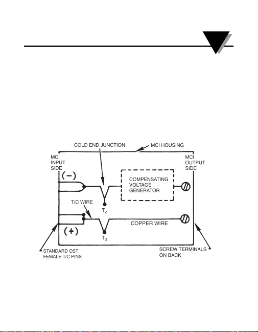
1.2 Theory of Operation
The MCJ contains a self-compensating voltage
generator that is built into a small housing. The input side
consists of the standard “OST” female pins that are
integral to the MCJ case (see Figure 1-2). On the output
side are two screw terminals that are connected to the
compensating voltage circuitry.
Figure 1-2. Inside the MCJ
Page 8

1-4
Introduction
1
This design incorporates a temperature sensitive element
that is thermally integrated with the “cold end” junctions
T2 and T3 (located inside the MCJ). In theory, as the
ambient temperature surrounding T2 and T3 varies, a
change in thermal emf is generated.
The thermal emf induced by this change in ambient
temperature will create an error in the output signal,
unless it is compensated for. To correct the error, an
equal and opposite voltage is automatically injected into
the circuit by the compensating voltage generator circuitry
of the MCJ. This, in turn, cancels out the emf error.
By integrating copper leads at the cold end junctions T2 and
T3, the thermocouple material itself is not directly connected
to the voltmeter, thereby eliminating induced errors. This
also eliminates the need to run thermocouple lead wires
from the output of the MCJ to the measuring device.
The compensating voltage generator in the MCJ is
temperature sensitive and produces a compensating emf
that tracks the error signal over a wide ambient
temperature range with a high degree of accuracy.
Page 9

2-1
Operating Instructions
2
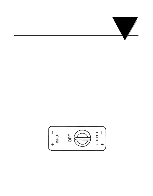
2.1 Battery Installation
The MCJ is provided with a 1.5 volt silver oxide battery
(part number MCJ-BATT-B). To install the battery, rotate
the black “OPEN-OFF-ON” switch counterclockwise
(CCW) to the position labeled OPEN. Carefully lift the
switch from the housing (see Figure 2-1).
Figure 2-1. Installing the Battery
Page 10

2-2
Operating Instructions
2
Install the battery into the MCJ body with the “+” side of
the battery facing downward. (Notice the “+” mark
scribed onto the silverplated battery contact spring inside
the MCJ.) After the battery is installed, re-assemble by
placing the black switch onto the MCJ body, being sure
to line up the switch arrow with the “OPEN” position.
Finally, rotate the switch clockwise to the OFF position.
2.2 To Test the Battery
With the battery installed, move the switch to the
OFF/BATTERY TEST position. Firmly depress the metal
pin on the switch and note the battery test indication light.
When lit, it indicates that the battery is good. If it does not
light up, replace the battery.
2.3 To Measure Temperature
The MCJ can be used in conjunction with a voltmeter to
accurately measure temperature. It will take the signal
from a thermocouple sensor and cancel out the error
introduced by the use of the copper wires leading to the
voltmeter.
Page 11

Operating Instructions
2
2-3
Figure 2-2. Operating with a Voltmeter
Page 12

2-4
Operating Instructions
2
Assemble the battery into the MCJ and test for power
(see Section 2.2). Connect a thermocouple sensor to
the INPUT side of the MCJ as described in this section.
Make sure the thermocouple sensor is the same
calibration as the MCJ (i.e. a type-K thermocouple
sensor must be used with the MCJ-K).
Refer to Figure 2-2. To attach a sensor to the MCJ,
simply plug in a Quick-Disconnect thermocouple probe
assembly directly into the INPUT side of the MCJ. Or,
you can wire a beaded thermocouple sensor to the
male OST connector that is supplied with the unit.
(When wiring your own sensor, be sure to attach the
RED wire of the thermocouple to the “-” terminal of the
OST connector.) Then plug the OST male connector
assembly into the INPUT side of the MCJ, as shown in
Figure 2-2.
Page 13

Operating Instructions
2
2-5
Next, connect COPPER wire from the OUTPUT screw
terminals of the MCJ to the voltmeter. The screw terminals are located on the back of the MCJ, behind the cap.
Wire the negative terminal on the MCJ to the negative
terminal on the voltmeter.
Turn ON the MCJ and the voltmeter. The voltmeter will
display a millivolt value that represents the compensated
millivolt signal produced by the thermocouple probe. That
value must then be translated into a temperature reading.
To translate a millivolt signal into a temperature value,
locate the “correct” Thermocouple Reference Table for
that particular thermocouple type. When using a type-K
probe, use the type-K Thermocouple Reference Table.*
Using the millivolt value given by the voltmeter display,
read the equivalent temperature value from the Table.
*See OMEGA Temperature Measurement Handbook and
Encyclopedia
®
, Technical Section.
Page 14

2-6
Operating Instructions
2
For example, if the voltmeter displays “1.520 mV”, you
need to translate that value into a temperature. If you are
using a type-K thermocouple, and want to know what that
is in degrees Fahrenheit, find the type-K Thermocouple
Reference Table (in Fahrenheit). Look through the
millivolt values until you find 1.520 mV.
Look to find that it is the equivalent to 100°F.
2.4 To Calibrate Thermocouple Instruments
The MCJ can also be used in conjunction with a
precision Millivolt Source in order to check and calibrate
Thermocouple Thermometers and other thermocoupleready instruments.
Page 15

Operating Instructions
2
2-7
Figure 2-3. Operating with a Millivolt Source
Page 16

2-8
Operating Instructions
2
Assemble the battery into the MCJ and test for power
(see Section 2.2). Connect the MCJ to the Millivolt
Source and the Meter to be calibrated (as shown in
Figure 2-3). Be sure to use thermocouple wire from the
Thermocouple Meter to the input terminals of the MCJ.
Use copper wires from the Millivolt Source to the MCJ.
Observe correct polarity when wiring.
Simulate a temperature value by “dialing-in” the correct
millivolt signal on the Millivolt Source. To do this, use the
correct Temperature vs. Millivolt Thermocouple Table for
that particular thermocouple type, and find the millivolt
signal that represents the temperature that you wish to
simulate.
The thermocouple meter display should be reading the
temperature equivalent to the millivolt signal that the
source is generating (within the accuracy of the
equipment being used).
Page 17

3-1
Troubleshooting and
Calibration
3
3.1 Troubleshooting the MCJ
The main sources of incorrect readings are grouped into
four categories:
1. Low battery voltage
2. Incorrect polarity on the MCJ thermocouple
input wiring
3. Incorrect polarity on the MCJ output copper wiring
4. Wrong thermocouple type used with MCJ
1. Check for sufficient battery voltage. See Section 2.2.
2. Plug in the thermocouple sensor into the MCJ and
connect to a voltmeter (Figure 2-2). Warm the
thermocouple junction. The voltmeter should go up
scale, that is, read more positive. If it goes down
scale instead when the probe is warmed, re-check the
polarity of the thermocouple wire. Correct it, if
necessary. (Remember that the RED thermocouple
wire is negative).
3. Another problem can occur when the MCJ is
incorrectly connected in the configuration as seen in
Page 18

3-2
Troubleshooting and Calibration
3
Figure 2-2. If the voltmeter shows a negative millivolt
reading, the wiring is wrong. Reverse the polarity of
the output wiring from the MCJ to the voltmeter. If
erratic readings occur, check for loose or broken
wires.
4. If you are sure that you have hooked up the MCJ
correctly, but are still getting incorrect readings,
check to see that you are using the correct calibration
of thermocouple probe, wire and MCJ through-out. A
type-J thermocouple probe will not read accurately
with a type-K MCJ.
3.2 Calibration
The MCJ is calibrated at the factory and is NOT designed
for field calibration. The warranty is void if the label of the
unit is tampered with in any way.
Page 19

4-1
Specifications
4
Fixed Reference Temp: 0°C (32°F) standard
Compensation Accuracy: 0.5°C from 15-30°C
(for standard reference (59-86°F) ambient
temp. setting)
Impedance: MCJ: less than 200 ohms
Use with instrumentation
having a source impedance
of 50K ohms or greater
Physical Dimensions:
Length: 75 mm (2.95")
Width: 25 mm (1.0")
Thickness: 12.7 mm (0.5")
Weight (with battery): Less than 56.7 gr. (2 ozs.)
Battery: Eveready No. EPX76,
1.5 volts or equivalent,
part no. MCJ-BATT-B
Page 20

4-2
Specifications
4
Battery Life: 2500 hours in continuous
operation. Store extra
batteries in cool place,
5-10°C (41-50°F)
Storage Temperature: -25 to 75°C (-13 to 167°F)
(without battery)
Page 21

5-1
Retrofit Kit
5
Pre-1996 MCJ’s are powered by a Mallory PX625 1.35
volt battery that is now difficult to obtain. The current
models are powered by Eveready No. EPX76 1.5 volt (or
equivalent). The two batteries are NOT
interchangeable.
Pre-1996 MCJ’s can be updated by ordering Retrofit Kit
Part Number MCJ-BATT-R that includes the 1.5 volt
battery and new switch/battery compartment assembly.
Page 22

5-2
5
NOTES:
Page 23

FOR WARRANTY RETURNS, please have the
following information available BEFORE contacting
OMEGA:
1. Purchase Order number under which the
product was PURCHASED,
2. Model and serial number of the product under
warranty, and
3. Repair instructions and/or specific problems
relative to the product.
FOR NON-WARRANTY REPAIRS,
consult OMEGA
for current repair charges. Have the following
information available BEFORE contacting OMEGA:
1. Purchase Order number to cover the COST
of the repair,
2. Model and serial number of the product, and
3. Repair instructions and/or specific problems
relative to the product.
OMEGA’s policy is to make running changes, not model changes, whenever an improvement is possible. This affords our customers the latest in technology and engineering.
OMEGA is a registered trademark of OMEGA ENGINEERING, INC.
© Copyright 2009 OMEGA ENGINEERING, INC. All rights reserved. This document may not be copied, photocopied, reproduced,
translated, or reduced to any electronic medium or machine-readable form, in whole or in part, without the prior written consent of
OMEGA ENGINEERING, INC.
WARRANTY / DISCLAIMER
OMEGA ENGINEERING, INC. warrants this unit to be free of defects in materials and workmanship for a
period of 13 months from date of purchase. OMEGA’s Warranty adds an additional one (1) month grace
period to the normal one (1) year product warranty to cover handling and shipping time. This
ensures that OMEGA’s customers receive maximum coverage on each product.
If the unit malfunctions, it must be returned to the factory for evaluation. OMEGA’s Customer Service
Department will issue an Authorized Return (AR) number immediately upon phone or written request.
Upon examination by OMEGA, if the unit is found to be defective, it will be repaired or replaced at no
charge. OMEGA’s WARRANTY does not apply to defects resulting from any action of the purchaser,
including but not limited to mishandling, improper interfacing, operation outside of design limits,
improper repair, or unauthorized modification. This WARRANTY is VOID if the unit shows evidence of
having been tampered with or shows evidence of having been damaged as a result of excessive corrosion; or current, heat, moisture or vibration; improper specification; misapplication; misuse or other
operating conditions outside of OMEGA’s control. Components in which wear is not warranted, include
but are not limited to contact points, fuses, and triacs.
OMEGA is pleased to offer suggestions on the use of its various products. However, OMEGA
neither assumes responsibility for any omissions or errors nor assumes liability for any
damages that result from the use of its products in accordance with information provided by
OMEGA, either verbal or written. OMEGA warrants only that the parts manufactured by the
company will be as specified and free of defects. OMEGA MAKES NO OTHER WARRANTIES
OR REPRESENTATIONS OF ANY KIND WHATSOEVER, EXPRESSED OR IMPLIED, EXCEPT
THAT OF TITLE, AND ALL IMPLIED WARRANTIES INCLUDING ANY WARRANTY OF
MERCHANTABILITY AND FITNESS FOR A PARTICULAR PURPOSE ARE HEREBY
DISCLAIMED. LIMITATION OF LIABILITY: The remedies of purchaser set forth herein are
exclusive, and the total liability of OMEGA with respect to this order, whether based on
contract, warranty, negligence, indemnification, strict liability or otherwise, shall not
exceed the purchase price of the component upon which liability is based. In no event shall
OMEGA be liable for consequential, incidental or special damages.
CONDITIONS: Equipment sold by OMEGA is not intended to be used, nor shall it be used: (1) as a “Basic
Component” under 10 CFR 21 (NRC), used in or with any nuclear installation or activity; or (2) in medical
applications or used on humans. Should any Product(s) be used in or with any nuclear installation or
activity, medical application, used on humans, or misused in any way, OMEGA assumes no
responsibility as set forth in our basic WARRANTY/ DISCLAIMER language, and, additionally, purchaser
will indemnify OMEGA and hold OMEGA harmless from any liability or damage whatsoever arising out
of the use of the Product(s) in such a manner.
RETURN REQUESTS / INQUIRIES
Direct all warranty and repair requests/inquiries to the OMEGA Customer Service Department. BEFORE
RETURNING ANY PRODUCT(S) TO OMEGA, PURCHASER MUST OBTAIN AN AUTHORIZED RETURN
(AR) NUMBER FROM OMEGA’S CUSTOMER SERVICE DEPARTMENT (IN ORDER TO AVOID PROCESSING DELAYS). The assigned AR number should then be marked on the outside of the return package and
on any correspondence. The purchaser is responsible for shipping charges, freight, insurance and proper packaging to prevent breakage in transit.
Page 24

M0060/0102
TEMPERATURE
䡺⻬
Thermocouple, RTD & Thermistor
Probes, Connectors, Panels &
Assemblies
䡺⻬
Wire: Thermocouple, RTD &
Thermistor
䡺⻬
Calibrators & Ice Point References
䡺⻬
Recorders, Controllers & Process
Monitors
䡺⻬
Infrared Pyrometers
PRESSURE, STRAIN
AND FORCE
䡺⻬
Transducers & Strain Gages
䡺⻬
Load Cells & Pressure Gages
䡺⻬
Displacement Transducers
䡺⻬
Instrumentation & Accessories
FLOW/LEVEL
䡺⻬
Rotameters, Gas Mass Flowmeters
& Flow Computers
䡺⻬
Air Velocity Indicators
䡺⻬
Turbine/Paddlewheel Systems
䡺⻬
Totalizers & Batch Controllers
pH/CONDUCTIVITY
䡺⻬
pH Electrodes, Testers & Accessories
䡺⻬
Benchtop/Laboratory Meters
䡺⻬
Controllers, Calibrators, Simulators
& Pumps
䡺⻬
Industrial pH & Conductivity
Equipment
DATA ACQUISITION
䡺⻬
Data Acquisition &
Engineering Software
䡺⻬
Communications-Based
Acquisition Systems
䡺⻬
Plug-in Cards for Apple, IBM
& Compatibles
䡺⻬
Data Logging Systems
䡺⻬
Recorders, Printers & Plotters
HEATERS
䡺⻬
Heating Cable
䡺⻬
Cartridge & Strip Heaters
䡺⻬
Immersion & Band Heaters
䡺⻬
Flexible Heaters
䡺⻬
Laboratory Heaters
ENVIRONMENTAL
MONITORING AND CONTROL
䡺⻬
Metering & Control Instrumentation
䡺⻬
Refractometers
䡺⻬
Pumps & Tubing
䡺⻬
Air, Soil & Water Monitors
䡺⻬
Industrial Water & Wastewater
Treatment
䡺⻬
pH, Conductivity & Dissolved
Oxygen Instruments
Where Do I Find Everything I Need for
Process Measurement and Control?
OMEGA…Of Course!
Shop online at omega.com
sm
 Loading...