

Page 1
User’s Guide
http://www.omega.com
e-mail: info@omega.com
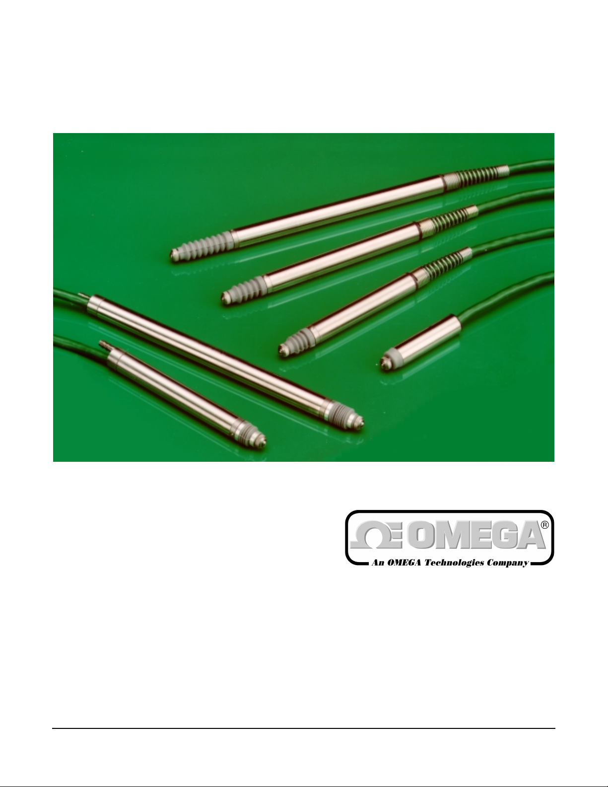
GP911 Series
Analog Gaging Transducers
GP911 Series M-3337 02/99
Page 1 of 12
Page 2

OMEGAnet® On-Line Service
http://www.omega.com
Internet e-mail
info@omega.com
Servicing North America:
USA: One Omega Drive, Box 4047
ISO 9001 Certified
Stamford, CT 06907-0047
Tel: (203) 359-1660 FAX: (203) 359-7700
e-mail: info@omega.com
Canada: 976 Bergar
Laval (Quebec) H7L 5A1
Tel: (514) 856-6928 FAX: (514) 856-6886
e-mail: info@omega.ca
For immediate technical or application assistance:
USA and Canada: Sales Service: 1-800-826-6342 / 1-800-TC-OMEGA
Customer Service: 1-800-622-2378 / 1-800-622-BEST
Engineering Service: 1-800-872-9436 / 1-800-USA-WHEN
TELEX: 996404 EASYLINK: 62968934 CABLE: OMEGA
Mexico and
Latin America: Tel: (95) 800-826-6342 FAX: (95) 203-359-7807
En Espan˜ol: (95) 203-359-7803 e-mail: espanol@omega.com
SM
SM
SM
Servicing Europe:
Benelux: Postbus 8034, 1180 LA Amstelveen, The Netherlands
Tel: (31) 20 6418405 FAX: (31) 20 6434643
Toll Free in Benelux: 0800 0993344
e-mail: nl@omega.com
Czech Republic: ul. Rude armady 1868, 733 01 Karvina-Hranice
Tel: 420 (69) 6311899 FAX: 420 (69) 6311114
Toll Free: 0800-1-66342 e-mail: czech@omega.com
France: 9, rue Denis Papin, 78190 Trappes
Tel: (33) 130-621-400 FAX: (33) 130-699-120
Toll Free in France: 0800-4-06342
e-mail: france@omega.com
Germany/Austria: Daimlerstrasse 26, D-75392 Deckenpfronn, Germany
Tel: 49 (07056) 3017 FAX: 49 (07056) 8540
Toll Free in Germany: 0130 11 21 66
e-mail: info@omega.de
United Kingdom: One Omega Drive, River Bend Technology Centre
ISO 9002 Certified
Northbank, Irlam, Manchester
M44 5EX, England
Tel: 44 (161) 777-6611 FAX: 44 (161) 777-6622
Toll Free in the United Kingdom: 0800-488-488
e-mail:
info@omega.co.uk
It is the policy of OMEGA to comply with all worldwide safety and EMC/EMI regulations that apply. OMEGA is constantly pursuing certification
of its products to the European New Approach Directives. OMEGA will add the CE mark to every appropriate device upon certification.
The information contained in this document is believed to be correct, but OMEGA Engineering, Inc. accepts
no liability for any errors it contains, and reserves the right to alter specifications without notice.
WARNING
GP911 Series M-3337 02/99
: These products are not designed for use in, and should not be used for, patient-connected applications
Page 2 of 12
.
Page 3

Contents
Product Description 4
Description ....................................................................................................................4
Installation Recommendations......................................................................................4
Electrical Connections for Use with Omega Electronics...............................................7
Location & Clamping........................................................................................4
Tip Tightness ...................................................................................................5
Zero Adjustment............................................................................................... 5
Cable................................................................................................................ 5
Pneumatic Options ..........................................................................................6
Adjustable Pretravel Option ............................................................................6
Environmental Considerations.........................................................................6
Quadrature Resistor......................................................................................... 7
GP911 Series M-3337 02/99
Page 3 of 12
Page 4

Product Description
Description
Omega Gaging Transducers are high precision measurement probes intended
for all Gaging applications demanding high accuracy and a high degree of
repeatability. The one piece parallel body houses a precision linear ball sleeve
bearing assembly, anti-rotation guide and the choice of either a half bridge or a
L.V.D.T. winding, a combination which adds up to an extremely versatile,
accurate and cost effective measurement solution.
Installation Recommendations
Location & Clamping
L.V.D.T. Gaging transducers generally are a reliable and proven technology that
is well established in all areas of manufacturing and quality control. The majority
of the associated problems experienced with their application and use are totally
avoidable, particularly if sufficient thought is given during the initial design stages
of equipment, to the position and clamping methods employed for these
measuring elements.
L.V.D.T.’s being of inductive nature are susceptible to some degree to the
influence of magnetic fields and therefore should be positioned well away from
electric motors, relays and permanent magnets, where this is not possible then
magnetic shielding should be considered as an alternative.
Clamping of the probe body should be carefully considered, ideally the body of
the transducer should be clamped in a pinch or yoke type clamp, if this is not
possible then the introduction of a load spreading bush between body and clamp
is a preferred alternative.
Irrespective of clamping method care must be taken not to overtighten retaining
screws as distortion of the body may prove damaging to the integrity of the
transducer and adversely effect the geometry of the installation.
Where single point screw clamping is adopted then the tightening torque
employed should be limited to that which will give a maximum of 50Kg point load.
The typical maximum torque for an M5x0.8mm or a 10-32UNF screw would be
approximately 0.27Nm.
GP911 Series M-3337 02/99
Page 4 of 12
Page 5

Tip Tightness
Standard measuring tips are factory tightened to a torque of between 0.18Nm
and 0.22Nm, this is sufficient to prevent loosening of the tip in use, but well within
the damage threshold of the anti-rotation mechanism. It is recommended that
replacement tips are tightened to the prescribed torque limits with the shaft fully
retracted. A proprietary thread locking anaerobic sealant may be used sparingly if
desired.
Zero Adjustment
This is best achieved by first positioning the Gage master, zeroing any electrical
offset control, selecting the course set gain and moving the Gaging probe into
contact with the master until the reading comes onto the scale. Gently tighten the
clamp until it is just possible to ”fidget” the probe manually towards the zero
indication.
As zero is approached, the instrument gain may be increased; when the zero
point is within the range of the zero offset controls the clamp must be fully
tightened. Any standard Omega probe used over the whole of its rated stroke
should be mechanically set to within 0.004” (0.10mm) of true zero, if the
measuring range is less than the rated stroke then the setting tolerance may be
increased proportionally to within the limits of the available electrical offset.
Cable
The transducer cable is specially manufactured to company specification to
achieve the optimum balance between flex life, flexibility, chemical resistance,
abrasion resistance and electrical characteristics such as electrostatic screening.
The following precautions will minimize transducer failure due to cable damage.
Cable runs should be positioned well clear of moving components and vulnerable
working areas. If the cable is in a flex situation then a minimum bend radius of 6”
(150mm) should be maintained, the vacuum and pneumatic options should not
be flexed from the transducer cable entry, but should be anchored separately at a
position of 2-3” (50-75mm) from the end cap.
Specials
All non-pneumatic probes are provided with a cable strain relief spring as
standard. This feature allows the user to retrospectively install a right angle cable
outlet to aid space or cable routing restrictions.
1.181”
30.0mm
Dimension
0.315”
8.0mm
0.335”
8.5mm
GP911 Series M-3337 02/99
Page 5 of 12
Page 6

Pneumatic Options
The Gaging tip of pneumatic probes is normally biased in the inward direction
and extension of the tip is achieved by applying air pressure to the probe nozzle.
Air pressure may be varied within the specified limits to achieve the desired tip
force at zero. The pneumatic probes are designed to be leak free and of small
volume to minimize the air flow requirements and maintain a consistent tip force.
Care must be taken not to damage the bellows seal as the satisfactory operation
of the probe is entirely dependent on this component. A working clearance
around the bellows equivalent to a 0.375” (9.5mm) dia. hole is desirable. To
maximize the working life of the probes the air supply should be both clean and
dry; i.e. filtered to better than 0.0002” (5 microns) and with a relative humidity of
less than 60%.
Operating Pressure Range for Standard Products : 0.4 Bar (6 psi) to 1.0 Bar (14
psi)
Vacuum Option
The Gaging tip of the vacuum operated probes is normally biased in the outward
direction and retracted by the application of negative pressure within the
specified ranges at the probe nozzle. Care must be taken not to damage the
bellows seal as the satisfactory operation of the probe is entirely dependent on
this component. Probes may be operated from a pumped system or individually
from a hand operated bulb.
Operating Pressure for Standard Products : 0.27 Bar (4 psi) maximum
Adjustable Pretravel Option
The option for adjustable pretravel is provided to maximize probe life and
minimize component damage where side application of the Gaged component is
necessary. Pretravel should be adjusted for minimum lift of the probe tip
necessary for a satisfactory Gaging operation within the tolerance of the Gaged
component.
Pretravel should only be adjusted using the spanner provided.
The pretravel adjustment is not provided as a means of fine mechanical zero
control, although it is possible to be used as such. Excessive use of the facility for
zero adjustment can result in loss of electrical datum, resulting in possible
damage to the internal stops.
Environmental Considerations
All non-pneumatic Gaging probes are specified to operate from +14°F to 176°F
(-10°C to +80°C) and all pneumatic probes from 41°F to 176°F (+5°C to +80°C).
At the low temperature extremes it may be necessary, due to stiffening, to
remove the rubber gaiter to achieve satisfactory operation. In this case the
atmosphere must be both clean and dry. However, continued operation without
the gaiter is not recommended due to the damage caused by the ingress of dirt.
Use of the transducer without the gaiter invalidates warranty. Omega probes are
designed to withstand the rigors of in-process Gaging and will operate
satisfactorily in the presence of copious amounts of coolants and cleaning
solvents.
GP911 Series M-3337 02/99
Page 6 of 12
Page 7

Electrical Connections for Use with Omega Electronics
Quadrature Resistor
These are supplied, where necessary to minimize residual voltage at null and
should be fitted as follows:
L.V.D.T
phase (see calibration sheet for details). Yellow wire is not connected in optional
factory fitted plugs.
.: Between yellow and white or yellow and green depending on
Half-Bridge
for details).
LVDT
Case
: Between yellow and red or yellow and blue (see calibration sheet
BLACK
CABLE SCREEN
BLUE
+
-
WHITE
YELLOW
GREEN
RED
GP911 Series M-3337 02/99
Page 7 of 12
Page 8

This Page Intentionally Left Blank
GP911 Series M-3337 02/99
Page 8 of 12
Page 9

This Page Intentionally Left Blank
GP911 Series M-3337 02/99
Page 9 of 12
Page 10

This Page Intentionally Left Blank
GP911 Series M-3337 02/99
Page 10 of 12
Page 11

WARRANTY/DISCLAIMER
OMEGA ENGINEERING, INC. warrants this unit to be free of defects in materials and workmanship for a period
13 months
of
normal
from date of purchase. OMEGA Warranty adds an additional one (1) month grace period to the
one (1) year product warranty
to cover handling and shipping time. This ensures that OMEGA’s
customers receive maximum coverage on each product.
If the unit malfunctions, it must be returned to the factory for evaluation. OMEGA’s Customer Service Department
will issue an Authorized Return (AR) number immediately upon phone or written request. Upon examination by
OMEGA, if the unit is found to be defective, it will be repaired or replaced at no charge. OMEGA’s WARRANTY
does not apply to defects resulting from any action of the purchaser, including but not limited to mishandling,
improper interfacing, operation outside of design limits, improper repair, or unauthorized modification. This
WARRANTY is VOID if the unit shows evidence of having been tampered with or shows evidence of having been
damaged as a result of excessive corrosion; or current, heat, moisture or vibration; improper specification;
misapplication; misuse or other operating conditions outside of OMEGA’s control. Components which wear are
not warranted, including but not limited to contact points, fuses, and triacs.
OMEGA is pleased to offer suggestions on the use of its various products. However, OMEGA neither
assumes responsibility for any omissions or errors nor assumes liability for any damages that result
from the use of its products in accordance with information provided by OMEGA, either verbal or written.
OMEGA warrants only that the parts manufactured by it will be as specified and free of defects. OMEGA
MAKES NO OTHER WARRANTIES OR REPRESENTATIONS OF ANY KIND WHATSOEVER, EXPRESS OR
IMPLIED, EXCEPT THAT OF TITLE, AND ALL IMPLIED WARRANTIES INCLUDING ANY WARRANTY OF
MERCHANTABILITY AND FITNESS FOR A PARTICULAR PURPOSE ARE HEREBY DISCLAIMED.
LIMITATION OF LIABILITY: The remedies of purchaser set forth herein are exclusive, and the total
liability of OMEGA with respect to this order, whether based on contract, warranty, negligence,
indemnification, strict liability or otherwise, shall not exceed the purchase price of the component upon
which liability is based. In no event shall OMEGA be liable for consequential, incidental or special
damages.
CONDITIONS: Equipment sold by OMEGA is not intended to be used, nor shall it be used: (1) as a “Basic
Component” under 10 CFR 21 (NRC), used in or with any nuclear installation or activity; or (2) in medical
applications or used on humans. Should any Product(s) be used in or with any nuclear installation or activity,
medical application, used on humans, or misused in any way, OMEGA assumes no responsibility as set forth in
our basic WARRANTY / DISCLAIMER language, and, additionally, purchaser will indemnify OMEGA and hold
OMEGA harmless from any liability or damage whatsoever arising out of the use of the Product(s) in such a
manner.
RETURN REQUESTS / INQUIRIES
Direct all warranty and repair requests/inquiries to the OMEGA Customer Service Department. BEFORE
RETURNING ANY PRODUCT(S) TO OMEGA, PURCHASER MUST OBTAIN AN AUTHORIZED RETURN (AR)
NUMBER FROM OMEGA’S CUSTOMER SERVICE DEPARTMENT (IN ORDER TO AVOID PROCESSING
DELAYS). The assigned AR number should then be marked on the outside of the return package and on any
correspondence.
The purchaser is responsible for shipping charges, freight, insurance and proper packaging to prevent breakage
in transit.
WARRANTY
FOR
RETURNS, please have the
following information available BEFORE contacting
OMEGA:
1. Purchase Order number under which the product
was PURCHASED,
2. Model and serial number of the product under
warranty, and
3. Repair instructions and/or specific problems
relative to the product.
NON-WARRANTY
FOR
REPAIRS, consult OMEGA for
current repair charges. Have the following information
available BEFORE contacting OMEGA:
1. Purchase Order number to cover the COST of the
repair,
2. Model and serial number of the product, and
3. Repair instructions and/or specific problems relative
to the product.
OMEGA’s policy is to make running changes, not model changes, whenever an improvement is possible.
This affords our customers the latest in technology and engineering.
OMEGA is a registered trademark of OMEGA ENGINEERING, INC.
© Copyright 1999 OMEGA ENGINEERING, INC. All rights reserved. This document may not be copied, photocopied,
reproduced, translated, or reduced to any electronic medium or machine-readable form, in whole or in part, without the prior
written consent of OMEGA ENGINEERING, INC.
GP911 Series M-3337 02/99
Page 11 of 12
Page 12

Where Do I Find Everything I Need for
Process Measurement and Control?
OMEGA…Of Course!
TEMPERATURE
Thermocouple, RTD & Thermistor Probes, Connectors, Panels & Assemblies
Wire: Thermocouple, RTD & Thermistor
Calibrators & Ice Point References
Recorders, Controllers & Process Monitors
Infrared Pyrometers
PRESSURE, STRAIN AND FORCE
Transducers & Strain Gauges
Load Cells & Pressure Gauges
Displacement Transducers
Instrumentation & Accessories
FLOW/LEVEL
Rotameters, Gas Mass Flowmeters & Flow Computers
Air Velocity Indicators
Turbine/Paddlewheel Systems
Totalizers & Batch Controllers
pH/CONDUCTIVITY
pH Electrodes, Testers & Accessories
Benchtop/Laboratory Meters
Controllers, Calibrators, Simulators & Pumps
Industrial pH & Conductivity Equipment
DATA ACQUISITION
Data Acquisition & Engineering Software
Communications-Based Acquisition Systems
Plug-in Cards for Apple, IBM & Compatibles
Datalogging Systems
Recorders, Printers & Plotters
HEATERS
Heating Cable
Cartridge & Strip Heaters
Immersion & Band Heaters
Flexible Heaters
Laboratory Heaters
ENVIRONMENTAL MONITORING AND CONTROL
Metering & Control Instrumentation
Refractometers
Pumps & Tubing
Air, Soil & Water Monitors
Industrial Water & Wastewater Treatment
pH, Conductivity & Dissolved Oxygen Instruments
GP911 Series M-3337 02/99
Page 12 of 12
 Loading...