

Page 1
VORTEX SHEDDING FLOWMETER AND
TEMPERATURE TRANSMITTER
For Water and Coolant
FV101 Series
U No Moving Parts to Jam
1
⁄4 FNPT to 4" Line Sizes
U
U LED Display
U 4 to 20 mA Output
U SSR Alarm
U Temperature Measurement
Units Feature Separate
4 to 20 mA Output and
SSR Alarm
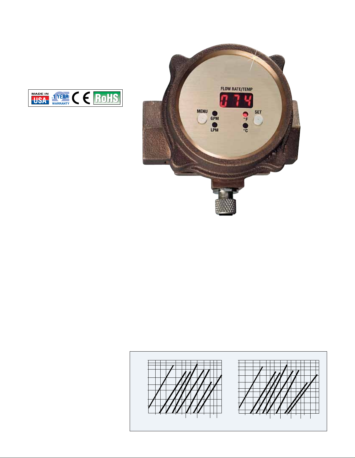
The FV101 Series comprises
in-line flowmeters that use the
vortex shedding measuring principle.
The fluid strikes a bluff body,
imparting alternating vortices
downstream of the bluff. This creates
a pressure on a sensor body
containing a piezoelectric crystal.
The frequency of the sensor is
proportional to the velocity of the
fluid and is amplified and converted
to a 4 to 20 mA output signal. Vortex
technology yields a meter with no
moving parts to hang up or wear.
The meter has a bright 7.62 mm
(0.3") high LED display of flow in
either liters or gallons. It can
measure flow in any direction, and
the display can be rotated 180° for
viewing convenience. The FV101
Series can be used with non-viscous,
clean, or dirty waterlike liquids that
are compatible with brass, PVDF,
and FKM. Measured fluids should
not contain long fibers or a high level
of abrasive solids. These meters are
ideal for cooling loops using water or
50% glycols, and for water-soluble
machine coolant (up to 10%). These
applications are found in most
process industries, including rubber,
steel, fabrication, manufacturing,
refining, paper, chemical, food,
petrochemical, and power. Do not
use on flammable liquids or on gases
such as air.
SPECIFICATIONS
Flow
Accuracy: ±2% FS
Repeatability: ±0.25% FS
Alarm Deadband: 5% FS
Response Time: User selectable
from 0.9 to 7.5 seconds
Max Flow: Over range occasionally
up to 125% of capacity
Temperature
Accuracy: ±1% FS
Response Time: 1.8 s to 63% of flow
Alarm Deadband: 2%
Display: 3-digit, 7.62 mm (0.3") high
numeric LED that flashes below setpoint
Maximum Operating Pressure:
2" and Smaller: 20 bar (300 psig)
3 and 4": 13 bar (200 psig)
Operating Temperature:
2 to 99°C (35 to 210°F)
Enclosure Rating:
IP65: Type 1, 3, 4, 12, and 13
Analog Output: 4 to 20 mA
(600 Ω @ 24 Vdc)
FV100 Pressure Drop Chart
12
)DISP( PORD ERUSSERP
10
8
5
2
1
.5
.2
.1
.05
.6 1 2 5 10 25 100
.3
MPG4
MPG21
MPG52
MPG05
FLOW (GPM)
MPG001
MPG003
006 MPG
MPG002
15 50 200 300
250 500
Electrical Connection:
FV100 Units (Flow Only): 5-pin
micro male connector,
FV100-T Units (Flow/Temperature):
8-pin male micro connector
Alarm Output: SPST SSR, NO or NC
operation, selectable; dual alarms for
flow/temperature units
FV101 and 102: 250 mA @ 30 Vdc
up to 85°C (185°F)
FV103 thru 108: 125 mA @ 30 Vdc
up to 85°C (185°F) reduced current
rating at higher temperatures
Power: 10 to 30 Vdc @ 80 mA
Wetted Parts: Brass, PVDF and
seals; 316 SS bodies available for
FKM
special order on
Flow Engineering for details.
Installation: 10 pipe diameters
upstream and 5 downstream
recommended
1000
750
500
350
200
RABILLIM
100
50
35
20
10
5
3.5
2 5 102050 200 600
FV103-T, shown
smaller than
actual size.
MPL51
L54 MP
9 MPL5
091 MPL
30 100 300 800
FLOW (LPM)
1
⁄4 and 1⁄2" sizes, contact
MPL083
067 MPL
MPL0011
1200
1500
L0032 MP
2000
G-3
Page 2
24 Vdc Supply
Temperature Relay Contact
4 to 20 mA Temperature Signal Out
Temperature Relay Contact
Flow Relay Contact
Flow Relay Contact
Supply and Chassis Ground
DC Ground
Internally
Connected
to Chassis
Load
Load
4 to 20 mA Flow Signal Out
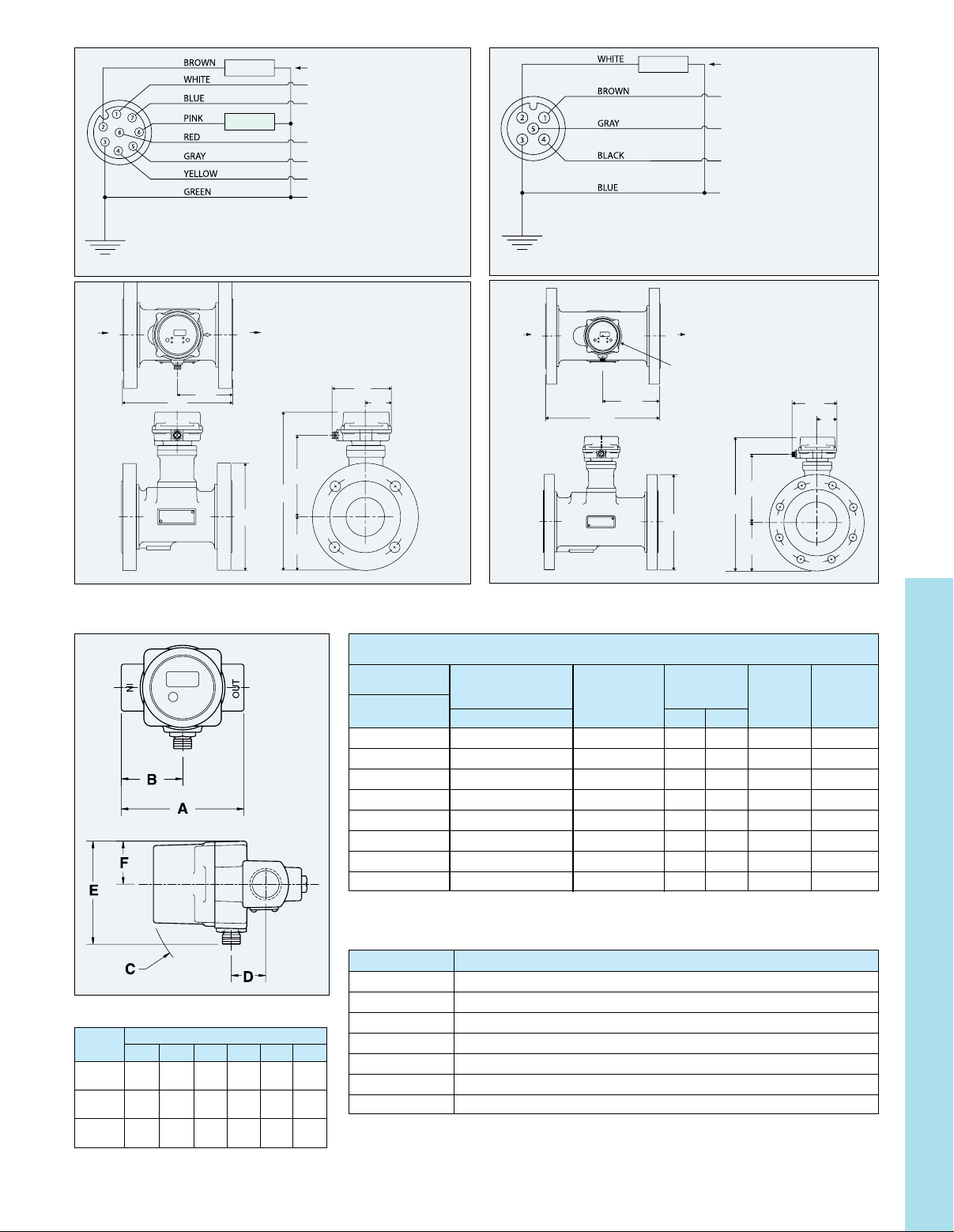
Wiring for FV100-T Series
Wiring for FV100 Series
Load
DC Ground
Internally
Connected
to Chassis
4 to 20 mA Flow Signal Out
24 Vdc Supply
Flow Relay Contact
Flow Relay Contact
Supply and Chassis Ground
FLOW IN
197
(7.75)
FLOW OUT
Cover Can Be Rotated
To Any of 4 Dentented Postions
in 90° Increments
99
(3.88)
ø190
(7.50)
(11.13)
Ø = diameter
Dimensions (1⁄4 thru 2" sizes)
3" Size Dimensions
Dimensions: mm (inch)
106
(4.19)
146
(5.73)
283
95
(3.75)
To Order Visit omega.com/fv100 for Pricing and Details
Flowmeter/
Flowmeter
Model
No.
FV101 — ¹⁄₄ FNPT 0.4 4 9.2 1.3 (2.8)
FV102 — ¹⁄₂ FNPT 1.2 12 3.6 1.2 (2.6)
FV103 FV103-T ³⁄₄ FNPT 2.5 25 3.6 2.9 (6.3)
FV104 FV104-T 1 FNPT 5 50 9.5 2.7 (5.9)
FV105 FV105-T 1¹⁄₂ FNPT 10 100 4.8 5.9 (13)
FV106 FV106-T 2 FNPT 20 200 4.9 4.8 (10.5)
FV107 FV107-T 3" ANSI RF 30 300 1.3 19 (42)
FV108 FV108-T 4" ANSI RF 60 600 1.3 25 (55)
FL OW I N
46
(1.78)
Temperature
Transmitter
Model No. Connection Min Max Max
273
(10.75)
37
(5.38)
FL OW O UT
OUT
Cover Can Be Rotated
To Any of 4 Dentented Postions
in 90° Increments
ø229
(9.00)
Flow
Range
(GPM)
4" Size Dimensions
Dimensions: mm (inch)
106
(4.19)
46
(1.78)
163
(6.43)
319
(12.57)
114
(4.50)
Pressure
Drop
psid Weight
kg (lb)
G
Size
(inch) A B C D E F
1
1
⁄
⁄
,
4
2
3
⁄
, 1
4
1
⁄
1
, 2
2
82 41 80 23 69 29
(3.25) (1.62) (3.13) (0.91) (2.74) (1.15)
115 58 103 53 106 45
(4.54) (2.27) (4.04) (2.08) (4.19) (1.78)
173 87 120 71 106 45
(6.82) (3.41) (4.71) (2.80) (4.19) (1.78)
mm (inch)
Accessories
Model No. Description
FV100-C1 Replacement 1 m (3') cable for FV100 Series
FV100-C3 3 m (9.8') cable for FV100 Series
FV100-C10 10 m (32.8') cable for FV100 Series
FV100-CT2 Replacement 2 m (6.5') cable FV100-T Series
FV100-CT5 5 m (16.4') cable for FV100-T Series
FV100-CT10 10 m (32.8') cable for FV100-T Series
PSR-24L 24 Vdc regulated power supply
Comes complete with operator’s manual and 1 m (3’) cable.
Ordering Examples: FV101,
FV104, 1 FNPT 5 to 50 GPM meter.
1
4
⁄
FNPT vortex meter, 0.4 to 4 GPM.
G-4
 Loading...