

Page 1
User’s Guide
Shop online at
omega.com
e-mail: info@omega.com
For latest product manuals:
omegamanual.info
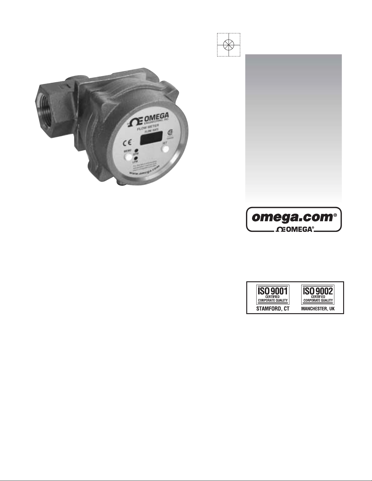
FV100/FV100-T Series
Installation & Operation Manual
on Vortex Shedding Flowmeter &
Temperature (optional) Transmitter
Page 2

OMEGAnet®Online Service Internet e-mail
omega.com
U.S.A.:
ISO 9001 Certified
Canada:
For immediate technical or application assistance:
U.S.A. and Canada:
info@omega.com
Servicing North America:
One Omega Drive, P.O. Box 4047
Stamford, CT 06907-0047
TEL: (203) 359-1660 FAX: (203) 359-7700
e-mail: info@omega.com
976 Bergar
Laval (Quebec) H7L 5A1, Canada
TEL: (514) 856-6928 FAX: (514) 856-6886
e-mail: info@omega.ca
Sales Service: 1-800-826-6342 / 1-800-TC-OMEGA
Customer Service: 1-800-622-2378 / 1-800-622-BEST
Engineering Service: 1-800-872-9436 / 1-800-USA-WHEN
TELEX: 996404 EASYLINK: 62968934 CABLE: OMEGA
®
®
®
Mexico:
Benelux:
Czech Republic:
France:
Germany/Austria:
United Kingdom:
ISO 9002 Certified
En Espan˜ol: (001) 203-359-7803 e-mail: espanol@omega.com
FAX: (001) 203-359-7807 info@omega.com.mx
Servicing Europe:
Postbus 8034, 1180 LA Amstelveen, The Netherlands
TEL: +31 (0)20 3472121 FAX: +31 (0)20 6434643
Toll Free in Benelux: 0800 0993344
e-mail: sales@omegaeng.nl
Frystatska 184, 733 01 Karviná, Czech Republic
TEL: +420 (0)59 6311899 FAX: +420 (0)59 6311114
Toll Free: 0800-1-66342 e-mail: info@omegashop.cz
11, rue Jacques Cartier, 78280 Guyancourt, France
TEL: +33 (0)1 61 37 2900 FAX: +33 (0)1 30 57 5427
Toll Free in France: 0800 466 342
e-mail: sales@omega.fr
Daimlerstrasse 26, D-75392 Deckenpfronn, Germany
TEL: +49 (0)7056 9398-0 FAX: +49 (0)7056 9398-29
Toll Free in Germany: 0800 639 7678
e-mail: info@omega.de
One Omega Drive, River Bend Technology Centre
Northbank, Irlam, Manchester
M44 5BD United Kingdom
TEL: +44 (0)161 777 6611 FAX: +44 (0)161 777 6622
Toll Free in United Kingdom: 0800-488-488
e-mail: sales@omega.co.uk
It is the policy of OMEGA Engineering, Inc. to comply with all worldwide safety and EMC/EMI
regulations that apply. OMEGA is constantly pursuing certification of its products to the European New
Approach Directives. OMEGA will add the CE mark to every appropriate device upon certification.
The information contained in this document is believed to be correct, but OMEGA accepts no liability for any
errors it contains, and reserves the right to alter specifications without notice.
WARNING: These products are not designed for use in, and should not be used for, human applications.
2
Page 3

CONTENTS
Subject Page
Specifications ....................................................................................... 3
Operation ............................................................................................. 4
Applications.......................................................................................... 4
Using this Manual................................................................................. 5
Model Plate Examples ......................................................................... 5
Name Plate Features ........................................................................... 5/6
Installation ............................................................................................ 6
Electrical/Wiring/Grounding.................................................................. 7
Wiring Diagrams................................................................................... 7
DC Power Supply Voltage Requirements ............................................ 8
Configuration/Setup ............................................................................. 8/9
FV100-T Indicators............................................................................... 10
Model Codes ........................................................................................ 10
Pressure Drop Data ............................................................................. 10
Cabling ................................................................................................. 3/ 10
Installation Dimensions ........................................................................ 11/12
3
Page 4

Specifications
Maximum operating pressure: 300 PSIG (20 Bar)
Minimum operating pressure: See page 6 & 10 (Pressure Drop Charts)
Maximum operating temperature (fluid and ambient): 185°F (85ºC), 186°F to 210°F (85ºC to 99ºC)
with reduced rating of the solid state relay.
Minimum operating temperature (fluid and ambient): 35°F (2ºC).
Maximum Flow: Meters may be over ranged, occasionally, up to 125% of capacity without damaging
the meter**
**Output is clamped at 21mA, 6.3% over range, display will indicate up to 125% FS
Capacities: 3/4" 25 GPM (95 LPM); 1" 50 GPM (190 LPM); 1 1/2" 100 GPM (380 LPM);
2" 200 GPM (750 LPM)
Process Connections: NPT female
Wetted Parts: Brass, PVDF & Viton
Enclosure Rating: Type 1, 3, 4, 12, & 13, IP65
Power Requirement: 10 - 30 Vdc @ 80 mA
Caution: The unit shall be supplied by a SELV (separated extra-low voltage) source in
accordance with CSA Standard C22.2 No.1010.1-92 Annex H.
Display: 3 digit LED digital display, 0.3" high
Environmental conditions: This device has been designed for use in Installation category I, pollution
degree 4, at altitudes up to 2000 meters (6560 ft.), either indoors or outdoors as defined in CSA Standard
C22.2 No.1010.1-92.
Flow (electrical)
Accuracy: ± 5% of Full Scale
Analog Output: 4-20 mA (600 ohm @ 24 Vdc) proportional to flow
Response Time: 1.5 seconds to 63% of step change
Repeatability: ± 0.25% of actual flow
Alarm Output: Low flow, Solid State SPST Relay, rated to 125 mA @ 30 Vdc, up to 185° F,
*50 mA @ 30 Vdc between 186° F & 210° F (85-99° C)
Alarm Deadband: 5% of full scale
Alarm State: NO or NC above setpoint (selectable)
Electrical Connection: 5-pin micro dc male connector
Temperature (electrical)
Accuracy: ± 1% of Full Scale
Analog Output: 4-20 mA (600 ohm @ 24 Vdc); 4 mA= 32° F (0° C) to 20 mA = 212° F (110° C)
Response Time: 1.5 seconds to 63% of step change
Repeatability: ± 0.25% of actual temperature
Alarm Output: High temperature, Solid State SPST Relay, rated to 125 mA @ 30 Vdc, up to 185° F,
*50 mA @ 30 Vdc between 185° & 210° F (85-99° C)
Alarm Deadband: 2% of full scale
Alarm State: Same as selected for Flow
4
Page 5

OPERATION
FV100 is an inline flow meter that utilizes the vortex shedding principle. The fluid strikes a bluff body
generating vortices (eddies) that move downstream. The vortices form alternately, from one side to the
other. A piezoelectric sensor housed in a sensor tube directly downstream of the bluff senses the pressure
zones created by the vortices. The sensor generates a frequency directly proportional to the vortices
(flow). The pulses are then amplified by the circuit board and converted to a 4-20 mA output, which is
also linear with flow. Flow can be displayed on the LED display in either GPM or LPM. Selection of the
preferred units of measure is made from two white front panel push buttons. There is also a solid state
relay output that can be set for a low flow contact from 15% to 90% of full-scale flow. The relay can be
configured to be NC (normally closed) or NO (normally open) at flow (above set point). It will change
state on decreasing flow upon reaching the setpoint.
FV100-T meters combine temperature measurement with the flow measuring features of FV100 Series.
The housing utilizes a temperature sensor housed in a small thermowell directly downstream of the flow
sensor. FV100-T meters display temperature or flow on the LED display. Temperature can be displayed
in either degrees Fahrenheit or Celsius and is selectable from the two white front panel buttons. There is
a 4-20 mA output proportional to temperature and a solid state relay that can be configured for a high
temperature set point. The relay function will be the same as selected for flow, normally closed or
normally open, below set point, since it is a high alarm. So, you have two transmitters in one - flow and
temperature.
APPLICATIONS
FV100/FV100-T can be used on low viscosity clean or dirty water-like liquids that are compatible with
brass, PVDF & Viton. Metered fluids should not include long fibers or a significant level of abrasive
solids. Bluffs are replaceable, as are the sensors, should abrasive wear occur over time. Typical applications will be for cooling loops using water, 50% solutions of glycols, and water soluble machine coolant
(up to 10%). These applications are found in most process industries, including rubber, steel, fabrication,
manufacturing, refining, paper, chemical, food, petrochemical and power. They cannot be used on
flammable liquids or gases including air.
NOTE: If this equipment is used in any manner not specified herein, the protection provided by the
equipment may be impaired.
Cleaning: These meters do not require any special cleaning of the external surfaces. If cleaning is
desired, do not use any strong solvents, detergents, or chemicals. Brushing away accumulations of dirt
or wiping with a cloth and water is suggested.
5
Page 6

USING THIS MANUAL
To use this manual, you will require the model code, which can be found on the nameplate of the meter,
as shown on the example below. See page 10 for “Model Codes.” The Model Code will allow you to
determine the minimum & maximum flow capabilities for each as well as related pressure drops.
All FV100 or FV100-T meters are equal in terms of features and functions. The only difference is the
flow capacity of the various sizes.
MODELPLATE EXAMPLES
FV100
FEATURES: FV100 Series
MENU
GPM
LPM
For the latest information
and product manual visit
w
w
ENGINEERING, INC.
FLOW METER
FLOW RATE
www.omegamanual.info
w
.
o
m
.
a
g
e
®
NRTL/C
154048
SET
m
o
c
6
Page 7

FEATURES: FV100-T Series
MENU
ENGINEERING, INC.
FLOW METER
FLOW RATE/TEMP
GPM
®
NRTL/C
154048
SET
°F
LPM
For the latest information
and product manual visit
www.omegamanual.info
w
w
w
.
o
m
°C
m
o
c
.
a
g
e
INSTALLATION
There are no upstream or downstream piping requirements to achieve the operating specifications given
herein. The meters may be installed in any position as long as good piping installation requirements are
adhered to for best results. This includes proper support of adjacent piping to minimize inherent vibrations produced within the system. Unions of the same pipe size and full port isolation ball valves may be
installed for ease of removal and servicing of equipment, if required. Meters should be placed in horizontal, slightly ascending runs or vertical runs to prevent entrained air from accumulating in the
meter. They should not be placed at the highest point in the piping for this same reason. Piping system
should be filled slowly to prevent water hammer from damaging sensor. The meter sensor can also be
damaged by reverse flow.
Isolation ball valves, when used, should be in the full open position. Throttling valves should always be
placed downstream of the meter, a minimum of 10 pipe diameters downstream.
Teflon® tape or pipe sealant can be used in mounting the meter to the piping when using good technique.
Teflon® tape, if not applied properly to the connecting piping, can become caught on the bluff and affect
the flow measurement.
Use of diaphragm or piston pumps will affect metering performance, unless they are installed with a
properly sized pulsation dampener and pressure control valve, to minimize pulsating flow. The piping
system must create some backpressure on the meter to allow vortex formation and to prevent cavitation,
especially at full flow. Minimum required back pressure is 10 PSIG at max flow and 70° F (21° C).
Higher back pressures are required at elevated temperatures and occasional surges to 125% of max flow.
This situation will not be encountered in most installations. If while increasing the flow, the signal or
displayed flow appears to drop off, but reappears when flow is reduced, contact OMEGA to determine
back pressure requirements to extend the flow range to the capacity of the meter.
7
Page 8

Electrical/Wiring/Grounding
Electrical Service: General Purpose
Electrical Classification: Non-hazardous Type 1, 2, 3, 4 (equal to IP 65), 12, & 13
Power Requirements: 24 VDC (10-30 VDC) @ 80 mA
Electrical Connections: 5-Pin micro style for FV100 or 8-Pin micro style for FV100-T, DC
Cabling: 5 or 8 Pin DC female shielded cable (do not connect shielding at the panel)
Grounding: Note, that DC and Chassis Grounds are internally connected to eliminate electrical
noise. If this poses a problem with your control wiring, please contact UFM for an alternative
solution.
Current Output: 4-20 mA (Note: Use of a 250 Ohm, 0.1%, 1/2 watt precision resistor will produce a 1-5
VDC signal for voltage input receivers)
Solid State Relay: Optically isolated, current limited to 125 mA @ 30 VDC up to 185° F (85° C), derated to 50 mA @ 30 VDC between 186° & 210° F (86° C to 99° C)
WIRING DIAGRAMS (Pin Configurations)
FV100 (FLOW ONLY) FV100-T (FLOW AND TEMPERATURE)
2
5
3
1
4
DC GROUND
INTERNALLY
CONNECTED
TO CHASSIS
WHITE
BROWN
GRAY
BLACK
BLUE
LOAD
4-20 mA FLOW SIGNAL OUT
+24 Vdc SUPPLY
FLOW RELAY CONTACT
FLOW RELAY CONTACT
SUPPLY & CHASSIS GROUND
PIN CONFIGURATION:
• 1: + 24 VDC power supply
• 2: 4-20 mA flow signal out
• 3: supply ground
• 4: flow relay contact
• 5: flow relay contact
2
3
1
7
6
8
5
4
DC GROUND
INTERNALLY
CONNECTED
TO CHASSIS
BROWN
WHITE
BLUE
PINK
RED
GRAY
YELLOW
GREEN
LOAD
LOAD
PIN CONFIGURATION:
• 1: + 24 VDC power supply
• 2: 4-20 mA flow signal out
• 3: supply ground
• 4: flow relay contact
• 5: flow relay contact
• 6: 4-20 mA temp signal out
• 7: temp relay contact
• 8: temp relay contact
4-20 mA FLOW SIGNAL OUT
+24 Vdc SUPPLY
TEMP RELAY CONTACT
4-20 mA TEMP SIGNAL OUT
TEMP RELAY CONTACT
FLOW RELAY CONTACT
FLOW RELAY CONTACT
SUPPLY & CHASSIS GROUND
8
Page 9

DC Power Supply Voltage Requirements
CONFIGURATION (Setup)
FV100 comes pre-calibrated and pre-configured in Gallons Per Minute, with the Solid State Relay set
for 0 flow, which inactivates the relay. To change the engineering units displayed to LPM, reset the solid
state relay for a minimum flow condition, or change the relay function (nc-normally closed or nonormally open) requires a simple reconfiguration. By powering up the meter, it can be reconfigured or
checked at the bench or installed position.
To configure the FV100 display for GPM or LPM, press the SET button so that the LED next to the
desired engineering unit is lit. To configure the set point, or alarm function, hold the MENU button
down until the display indicates “flo”, then “AL”, then release it. The LED display will indicate zeros or
a set point. Change the setting, by pressing the MENU button. Each time it is pressed, it will step the set
point upwards, holding it down will ramp the set point up quickly until the desired set point is approached, then pressing discreetly will step it up to the desired setting. At the highest setting for each
meter capacity, it will roll over to 0. Then as the MENU button is pressed it will step or ramp up if held
down. Once the desired set point is displayed, use the SET button to enter the value.
If no set point is required, then select 0 with the SET button - this will inactivate the relay, as well as the
local LED indicator, which flashes on reaching the set point. The two LED indicators that are adjacent to
GPM & LPM flash when the flow drops to or below the set point. If GPM has been selected, it will
remain on solid and the LPM indicator will flash. The opposite occurs when LPM is the selected unit of
measure displayed.
9
Page 10

CONFIGURATION (Setup) continued...
The next parameter, relay function, will automatically appear. It may indicate “nc”, normally closed, or
“no”, normally open. Pressing the MENU button will change the relay function from one to the other.
To select the desired relay condition, merely press the SET button. The relay function selected is at the
normal flow condition, above set point. So, by selecting “no”, the relay will be open above the set point
and close on reaching the set point or lower. Conversely, if “nc” is selected, the relay will be closed
above the set point and open at or below set point.
Once the relay function is set, the meter will return to the run mode. If no flow is present, the meter
should display zeros and the LED adjacent to the unit of measure not selected will be flashing to indicate
a low flow condition (unless a set point of zero was selected).
FV100-T includes the features of FV100 plus temperature. FV100-T has a second set of LED’s adjacent
to the SET button. One is labeled F, for degrees Farenheit, and the second C, for degrees Celcius.
To setup the flow portion of FV100-T, the flow variable must be displayed. Pressing the MENU button
one time, toggles between the displayed variables of flow and temperature. Press the MENU button
once if temperature is the displayed variable. Then complete the setup for the flow variable as, described
above under FV100.
To configure the temperature portion of FV100-T , press the MENU once, if the temperature variable is
not displayed. Temperature, since it is being measured on power up, will be displayed as degrees F or C
dependent upon the status of the LED indicators adjacent to the two units of measure. To enter a set
point, hold the MENU button down until “t”, then “AL” are displayed, consecutively. The display will
then indicate the set point. To change, press the MENU button to step the value upward, or hold the
MENU button down to quickly ramp up the setting, releasing as the desired value is approached, and
then pressing incrementally until the set point is reached. Then press the SET button to enter the selected value. Again, as in the flow set point, if the set point is passed, continue holding the MENU
button down and it will roll over to zero and continue increasing until released and incremented slowly
to the desired value. After selecting the set point the meter will return to the run mode.**
**NOTE: The relay function for temperature is the same as selected for flow. If the “nc”, normally closed condi-
tion is selected for flow, it will also function the same way for temperature. The relay function (status) is always at
the normal condition. So, if “nc” is selected, the relay will be closed above the flow set point and below the
temperature set point. That is because we are normally looking for a low flow condition and a high temperature
condition in cooling applications. When either set point is reached for flow or temperature, its respective relay
will change state. The set points, when selected in either GPM or LPM and F or C, will automatically con-
vert to the correct value, if the other unit of measure is selected.
10
Page 11

FV100-T LED Indicators
The LED’s adjacent to the engineering units of GPM, LPM, F, & C have two functions. The first is to
indicate the process variable being displayed and its respective engineering unit, the second to indicate
alarm conditions. If temperature is being displayed, say 75 F, then 75 will appear in the display and the
LED adjacent to F will be lit. If the temperature would increase to its respective set point, then the actual
value will be displayed, the F LED will remain lit and the LED adjacent to C would begin flashing. If, at
the same time, there is a low flow condition, both LED’s next to GPM & LPM will also flash - indicat-
ing a flow fault also, so that you can press the MENU button to verify the flow rate.
In either case, if flow or temperature is the displayed value, when a fault condition occurs on the
nondisplayed value, the two indicator LED’s associated with that variable will both flash to provide
a local indication of a fault. The solid state relays will still function independently, also regardless of the
variable being displayed. As will the 4-20 mA outputs.
MODEL CODES
MODEL CODE SELECTION
Code Flow Flow and Pipe Size Flow Range
FV103 x 3/4 2.5 25 9 95
FV103-T x 3/4 2.5 25 9 95
FV104 x 1 5 50 20 190
FV104-T x 1 5 50 20 190
FV105 x 1 1/2 10 100 40 380
FV105-T x 1 1/2 10 100 40 380
FV106 x 2 20 200 75 750
FV106-T x 2 20 200 75 750
Only Temperature in Inches GPM LPM
Min Max Min Max
PRESSURE DROP CHARTS
12
10
8
5
2
1/4 IN.
1
.5
.2
.1
PRESSURE DROP (PSID)
.05
.6 1 2 5 10 25 100
.3
1/2 IN.
3/4 IN.
15 50 200 300
FLOW (GPM)
1 IN.
1-1/2 IN.
2 IN.
250
1000
750
500
350
200
100
50
35
MILLIBAR
20
10
5
3.5
25102050 200 600
1/4 IN.
1/2 IN.
3/4 IN.
FLOW (LPM)
1 IN.
1-1/2 IN.
2 IN.
30 100 300 800
11
1200
CABLING AV AILABLE with METERS
Series Description Length in Part
Meters Number
FV100 5 pin 1 FV100-C1
female 3 FV100-C2
10 FV100-C3
FV100-T 8 pin 1 FV100-CT1
female 3 FV100-CT2
10 FV100-CT3
Page 12

Installation Dimensions
INSTALLATION DRAWINGS
Size A B C D E F
3/4" & 1" 4.54 2.27 4.04 2.08 4.19 1.78
[115mm] [58mm] [103mm] [53mm] [106mm] [45mm]
1 1/2" & 2" 6.82 3.41 4.71 2.80 4.19 1.78
[173mm] [87mm] [120mm] [71mm] [106mm] [45mm]
Installation Drawings, 3/4" & 1"
COVER CAN BE ROTATED TO ANY
OF (4) DETENTED POSITIONS
IN 90° INCREMENTS.
1.78
[45mm]
IN
4.54
[115mm]
2.27
[58mm]
OUT
4.19
[106mm]
R4.04 [103mm]
APPROX. SWING RADIUS
4.93
[125mm]
2.08
[53mm]
1.20
[30mm]
12
Page 13

IN
Installation Drawing, 1 1/2" & 2"
COVER CAN BE ROTATED TO ANY
OF (4) DETENTED POSITIONS
IN 90° INCREMENTS.
OUT
4.19
[106mm]
1.78
[45mm]
6.82
[173mm]
3.41
[87mm]
R4.71 [120mm]
APPROX. SWING RADIUS
2.80
[71mm]
6.16
[156mm]
1.72
[44mm]
13
M-4117/1104
Page 14

WARRANTY/DISCLAIMER
OMEGA ENGINEERING, INC. warrants this unit to be free of defects in materials and workmanship for a
period of 13 months from date of purchase. OMEGA’s WARRANTY adds an additional one (1) month
grace period to the normal one (1) year product warranty to cover handling and shipping time. This
ensures that OMEGA’s customers receive maximum coverage on each product.
If the unit malfunctions, it must be returned to the factory for evaluation. OMEGA’s Customer Service
Department will issue an Authorized Return (AR) number immediately upon phone or written request.
Upon examination by OMEGA, if the unit is found to be defective, it will be repaired or replaced at no
charge. OMEGA’s WARRANTY does not apply to defects resulting from any action of the purchaser,
including but not limited to mishandling, improper interfacing, operation outside of design limits,
improper repair, or unauthorized modification. This WARRANTY is VOID if the unit shows evidence of
having been tampered with or shows evidence of having been damaged as a result of excessive corrosion;
or current, heat, moisture or vibration; improper specification; misapplication; misuse or other operating
conditions outside of OMEGA’s control. Components in which wear is not warranted, include but are not
limited to contact points, fuses, and triacs.
OMEGA is pleased to offer suggestions on the use of its various products. However,
OMEGA neither assumes responsibility for any omissions or errors nor assumes liability for any
damages that result from the use of its products in accordance with information provided by
OMEGA, either verbal or written. OMEGA warrants only that the parts manufactured by the
company will be as specified and free of defects. OMEGA MAKES NO OTHER WARRANTIES OR
REPRESENTATIONS OF ANY KIND WHATSOEVER, EXPRESSED OR IMPLIED, EXCEPT THAT OF
TITLE, AND ALL IMPLIED WARRANTIES INCLUDING ANY WARRANTY OF MERCHANTABILITY
AND FITNESS FOR A PARTICULAR PURPOSE ARE HEREBY DISCLAIMED. LIMITATION OF
LIABILITY: The remedies of purchaser set forth herein are exclusive, and the total liability of
OMEGA with respect to this order, whether based on contract, warranty, negligence,
indemnification, strict liability or otherwise, shall not exceed the purchase price of the
component upon which liability is based. In no event shall OMEGA be liable for
consequential, incidental or special damages.
CONDITIONS: Equipment sold by OMEGA is not intended to be used, nor shall it be used: (1) as a “Basic
Component” under 10 CFR 21 (NRC), used in or with any nuclear installation or activity; or (2) in medical
applications or used on humans. Should any Product(s) be used in or with any nuclear installation or
activity, medical application, used on humans, or misused in any way, OMEGA assumes no responsibility
as set forth in our basic WARRANTY/DISCLAIMER language, and, additionally, purchaser will indemnify
OMEGA and hold OMEGA harmless from any liability or damage whatsoever arising out of the use of the
Product(s) in such a manner.
RETURN REQUESTS/INQUIRIES
Direct all warranty and repair requests/inquiries to the OMEGA Customer Service Department. BEFORE
RETURNING ANY PRODUCT(S) TO OMEGA, PURCHASER MUST OBTAIN AN AUTHORIZED RETURN
(AR) NUMBER FROM OMEGA’S CUSTOMER SERVICE DEPARTMENT (IN ORDER TO AVOID
PROCESSING DELAYS). The assigned AR number should then be marked on the outside of the return
package and on any correspondence.
The purchaser is responsible for shipping charges, freight, insurance and proper packaging to prevent
breakage in transit.
FOR
WARRANTY RETURNS, please have the
following information available BEFORE
contacting OMEGA:
1. Purchase Order number under which the product
was PURCHASED,
2. Model and serial number of the product under
warranty, and
3. Repair instructions and/or specific problems
relative to the product.
OMEGA’s policy is to make running changes, not model changes, whenever an improvement is possible. This affords
our customers the latest in technology and engineering.
OMEGA is a registered trademark of OMEGA ENGINEERING, INC.
© Copyright 2004 OMEGA ENGINEERING, INC. All rights reserved. This document may not be copied, photocopied,
reproduced, translated, or reduced to any electronic medium or machine-readable form, in whole or in part, without the
prior written consent of OMEGA ENGINEERING, INC.
FOR NON-WARRANTY REPAIRS,
for current repair charges. Have the following
information available BEFORE contacting OMEGA:
1. Purchase Order number to cover the COST
of the repair,
2. Model and serial number of the product, and
3. Repair instructions and/or specific problems
relative to the product.
consult OMEGA
14
Page 15

Where Do I Find Everything I Need for
Process Measurement and Control?
OMEGA…Of Course!
Shop online at omega.com
TEMPERATURE
䡺⻬
Thermocouple, RTD & Thermistor Probes, Connectors, Panels & Assemblies
䡺⻬
Wire: Thermocouple, RTD & Thermistor
䡺⻬
Calibrators & Ice Point References
䡺⻬
Recorders, Controllers & Process Monitors
䡺⻬
Infrared Pyrometers
PRESSURE, STRAIN AND FORCE
䡺⻬
Transducers & Strain Gages
䡺⻬
Load Cells & Pressure Gages
䡺⻬
Displacement Transducer s
䡺⻬
Instrumentation & Accessories
FLOW/LEVEL
䡺⻬
Rotameters, Gas Mass Flowmeters & Flow Computers
䡺⻬
Air Velocity Indicators
䡺⻬
Tu rbine/Paddlewheel Systems
䡺⻬
To talizers & Batch Controllers
pH/CONDUCTIVITY
䡺⻬
pH Electrodes, Testers & Accessorie s
䡺⻬
Benchtop/Laboratory Meters
䡺⻬
Controllers, Calibrators, Simulators & Pumps
䡺⻬
Industrial pH & Conductivity Equipment
DATA ACQUISITION
䡺⻬
Data Acquisition & Engineering Software
䡺⻬
Communications-Based Acquisition Systems
䡺⻬
Plug-in Cards for Apple, IBM & Compatibles
䡺⻬
Datalogging Systems
䡺⻬
Recorders, Printers & Plotters
HEATERS
䡺⻬
Heating Cable
䡺⻬
Cartridge & Strip Heaters
䡺⻬
Immersion & Band Heaters
䡺⻬
Flexible Heaters
䡺⻬
Laboratory Heaters
ENVIRONMENTAL
MONITORING AND CONTROL
䡺⻬
Metering & Control Instrumentation
䡺⻬
Refractometers
䡺⻬
Pumps & Tubin g
䡺⻬
Air, Soil & Water Monitors
䡺⻬
Industrial Water & Wastewater Treatment
䡺⻬
pH, Conductivity & Dissolved Oxygen Instruments
15
M-4117/1104
 Loading...