

Page 1
FPD1000-HP SERIES
HIGH PRESSURE
Positive Displacement Flowmeters
Page 2

Page 3
To the owner:
Thank you for purchasing an OMEGA FPD
Series Flowmeter. Please take a few minutes to read through the manual before installing and operating your meter. If you
have any problems with the meter, refer to
the Maintenance and Troubleshooting sections of the manual.
This manual contains connection and operating instructions for the OMEGA FPD
Series meters with pulse outputs. This includes the following models:
FPD1202-HP FPD1203-HP
The OMEGA FPD Series flowmeter has incorporated the oval rotor principal into its
design. This has proven to be a reliable and
highly accurate method of measuring flow.
Exceptional repeatability and high accuracy
over a wide range of fluid viscosities and
flowrates are features of the OMEGA FPD
Series flowmeter design. With low pressure
drop and high pressure rating, means the
OMEGA FPD Series flowmeters are suitable for both gravity and pump (in-line) applications.
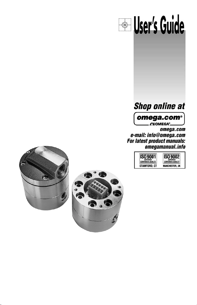
INSTALLATION
1. Use thread sealant on all pipe threads.
2. Ensure the meter is installed so that
rotor shafts are always in a horizontal
plane (See Figure 1). Flow is bi-directional.
Figure 1
DO NOT install
meter this way.
3. OMEGA recommends use of flexible
connections.
4. Extreme care must be taken when installing the meter. Pipe strain or overtightening meter connections can
cause meter damage.
PULSER DETAILS
IMPORTANT INFORMATION
Please read this information
!
▲
carefully before use!
Before use, confirm the fluid to be used is
compatible with the meter or consult with
OMEGA for advice.
To prevent damage from dirt or foreign
matter, OMEGA recommends a Y or basket type 200 mesh strainer be installed as
close as possible to the inlet side of the
meter. (If required, contact OMEGA for further information.)
To prevent damage to the meter, slowly fill
the system with fluid. This will prevent damage caused by air purge.
NOTE: Failure to do this could damage the
meter.
For pump applications, turn off the pump
at the end of each day.
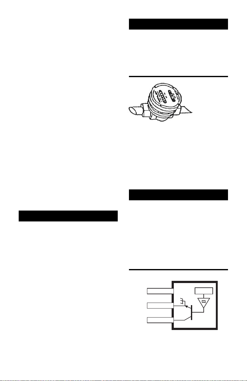
Hall Effect Sensor Specifications
•4.5 V to 24 V (4.6 - 9 mA) operation
needs only an unregulated supply.
•Open collector 25 mA output NPN
(Current Sink) compatible with digital
logic.
•Reverse battery precaution.
Figure 2
Supply
Signal
Ground
12 3
Hall Effect Sensor Wiring Details
V
cc
(HP Models Only)
X
1
Page 4

Reed Relay Specifications
•Two wire SPST N/O.
•Switching voltage 150 VDC; maximum
current 0.25 Amps.
•Rating 3 watts.
•Duty cycle 20% ON, 80% OFF.
Figure 3
12
Reed Switch Wiring Details
(HP Models Only)
MAINTENANCE
Disassembly:
1. Ensure the fluid supply to the meter has
been disconnected, and the line pressure has been released before disassembly.
2. Remove the four screws and remove the
pulser cap.
3. Remove the gasket.
4. Remove eight screws and remove the
meter cap.
5. Remove O-ring and inspect. Replace Oring if damaged.
6. Remove rotors, clean and inspect. Replace rotors if damaged.
7. To remove the PCB, remove the two
screws.
NOTE: Reed Switch PCB’s cannot be re-
moved.
Reassembly:
1. Replace rotors into the meter body. The
rotors should be at 90 degrees to each
other.
2. Lightly rotate the rotors by hand. They
must rotate freely.
3. Install O-ring.
4. Replace the meter cap and tighten the
eight screws uniformly to 35Nm (25 Ft.
Lbs.).
5. Replace the pulser cap and tighten the
four screws.
2
Page 5

TROUBLESHOOTING
Symptom Probable Cause Corrective Action
FLUID WILL NOT 1. Foreign matter blocking Dismantle meter, clean rotors. Strainer must
FLOW THROUGH rotors be fitted in-line.
THE METER
REDUCED FLOW 1. Line strainer partially Clean strainer.
THROUGH THE blocked
METER
METER READING 1. Fluid flowrate is too low See specifications for minimum and
INACCURATE or too high maximum flowrates.
METER NOT 1. Faulty Hall Effect sensor Replace meter cap for Reed Switch models,
GIVING A PULSE or Reed Switch replace PCB for Hall Effect models.
SIGNAL
2. Line strainer blocked Clean strainer.
3. Damaged rotors Replace rotors. Strainer must be fitted in-line.
4. Meter connections over- Re-adjust connections.
tightened
2. Fluid is too viscous Maximum viscosity 1000 centipoise.
2. Air in fluid. Bleed air from system.
3. Excess wear caused by Check meter for damage. Install correctly.
incorrect installation
2. Faulty magnet Replace rotors.
3
Page 6

DISPLAY PARTS LISTING
3
Model: FPD1202-HP
4
TERMINAL
BLOCK
2
7
1
u = Recommended Spare Parts to stock.
Bold Text = Indicates Stainless Steel model parts.
Item Rec. Part or Set
No. Qty. Parts (Order from this column only) Part Description
11 MS1NS Meter Body Assembly NPT
28 u MS367S Bolt Set - Socket Head
31 MS170H Pulser Cap (BSP)
31 MS170HN Pulser Cap (NPT)
44 uMS115S Bolt Set - Socket Head
61 MS3HES Meter Cap & Hall Effect Assembly
61 MS3HPS Meter Cap & Reed Switch Assembly
72 uMS6-1S Rotor Set (Stainless Steel)
81 u BS029V O-Ring (Viton)
81 u BS029TE O-Ring (Kalrez)
91 MS300HS Gasket
10 1 MS284S Screw Sets
9
10
6
8
*
*
Reed Switch & Hall Effect are unavailable without meter cap.
*
4
Page 7

SPECIFICATIONS
Pulse Meter Models
Flow Ranges (LPM or GPM)
Above 5 centipoise 2 to 100 / 0.53 to 26.4
Below 5 centipoise 5 to 100 / 1.32 to 26.4
Accuracy of Reading ± 1%
Maximum Viscosity 1000 Centipoise
Maximum Operating Pressure 55160 kPa / 8000 PSI / 551 Bar
Maximum Operating Temperature 120°C / 248°F
Pulse Type Hall Effect Sensor / Reed Switch
Pulses per Litre/Gallons 1000 / 3785
Meter Dimensions 86mm Dia. / 3.4” Dia. (Meter Body)
83mm / 3.25” (Port Face to Face)
Weight 3.3 kg / 116 oz.
5
Page 8

DISPLAY PARTS LISTING
3
Model: FPD1203-HP
4
TERMINAL
9
BLOCK
10
2
7
1
u = Recommended Spare Parts to stock.
Bold Text = Indicates Stainless Steel model parts.
Item Rec. Part or Set
No. Qty. Parts (Order from this column only) Part Description
11 MS2NS Meter Body Assembly NPT
28 u MS367S Bolt Set - Socket Head
31 MS170H Pulser Cap (BSP)
31 MS170HN Pulser Cap (NPT)
44 uMS115S Bolt Set - Socket Head
61 MS3HES Meter Cap & Hall Effect Assembly
61 MS3HPS Meter Cap & Reed Switch Assembly
72 u MS7-1ES Rotor Set (S/Steel) - Hall Effect
72 uMS7-1RS Rotor Set (S/Steel) - Reed Switch
72 uMS7-1HES Rotor Set (S/Steel) - Hall Effect, High Visc.
72 uMS7-1HRS Rotor Set (S/Steel) - Reed Switch, High Visc.
81 u BS029V O-Ring (Viton)
81 u BS029TE O-Ring (Kalrez)
91 MS300HS Gasket
10 1 MS284S Screw Sets
6
8
*
*
Reed Switch & Hall Effect are unavailable without meter cap.
*
6
Page 9

SPECIFICATIONS
Pulse Meter Models
Flow Ranges (LPM or GPM)
Above 5 centipoise 15 to 500 / 4.0 to 132
Below 5 centipoise 25 to 500 / 6.0 to 132
Accuracy of Reading ± 1%
Maximum Viscosity
Maximum Operating Pressure 55160 kPa / 8000 PSI / 551 Bar
Maximum Operating Temperature 120°C / 248°F
Pulse Type Hall Effect Sensor / Reed Switch
Pulses per Litre/Gallons 400 / 1514
Meter Dimensions 86mm Dia. / 3.4” Dia. (Meter Body)
Weight 3.3 kg / 116 oz.
Unless high viscosity rotors are fitted.
*
*
1000 Centipoise
83mm / 3.25” (Port Face to Face)
7
Page 10

Page 11

Page 12

M-4125 / 0405
 Loading...