

Page 1

Local Model
Remote Model
FPD1000D-A
and FPD1000D-TX
4-20 mA Transmitter with Display
Local and Remote Models
Page 2

Page 3

GENERAL INFORMATION
This manual will assist you in operating
and maintaining your OMEGA 4-20 mA
Transmitter with Display used in conjunction
with the FPD Series Oval Gear Meters. This
manual provides information on both the
Local and Remote models of the 4-20 mA
Transmitter with Display.
• Choose the Local model (mounted to
the meter) when local monitoring is required and 4-20 mA output is needed.
• Choose the Remote model when remote monitoring is required and 4-20
mA output is needed.
CAUTION
This transmitter is not FM Approved.
Therefore, use of this transmitter with
an approved metering system voids FM
Approval.
NOTE: This transmitter is loop powered,
requiring an input power supply of 8.5 to
35 volts (24 VDC is recommended).
NOTE: Setpoint calibration of the transmitter
is required for the 4-20 mA, 0-20 mA,
and 0-5 V output options.
SAFETY INSTRUCTIONS
PRODUCT DESCRIPTION
The OMEGA Remote Transmitter is a
flow totalizer and rate meter with industry
standard current loop output. The Remote
Transmitter accepts input pulses from the
FPD Series meter or other frequency generating devices, and uses those pulses to
calculate the flow total and rate in a pipeline.
The unit is loop powered, and provides a
4-20 mA analog output proportional to the
frequency signal for communication with
PLCs and other customer equipment. The
4-20 mA (or 0-20 mA) output is calibrated
under actual flow conditions with simple
push-button calibration. Auxiliary output
includes 0-5 VDC and pulse output (Reed
Switch option only). The transmitter can be
pipe or wall mounted.
The microprocessor-based electronics
have extremely low power requirements
an d are comp let ely powe red by the
4-20 loop. The electronics provides the options of local (on the meter) and/or remote
(up to 5,000 feet) display. Flow total and
rate are displayed on a large 6-digit LCD
readout with two-point floating decimal for
totals from .01 to 999,999. All operations
are easily accessed with the push buttons
on the display front panel.
• When measuring flammable liquids,
observe precautions against fire or
explosion.
• When working in hazardous environments, always exercise appropriate
safety precautions.
• When applying external power to the
transmitter, use DC power only.
• Disconnect external power to the transmitter before detaching or attaching
input or output wires.
• Ground loops between sensor and user
equipment can damage the transmitter
and can be dangerous.
• If you cannot galvanically isolate the
sensor from earth ground, you may
need to use the transmitter’s optically
isolated inputs.
• Be sure O-rings and seals are kept in
good repair.
1
Page 4

INSTALLATION
CAU T I O N
Installation should be performed only by
qualified personnel, and in accordance
with local governing regulations.
Environmental
Choose a mounting location suitable for
the remote transmitter. The ideal mounting
location is where the:
• meter is as close as possible.
• mounting surface has minimal vibration.
• ambient temperature is +30°F to +140°F
(0°C to +60°C) when using remote display.
• cable lengths are minimal.
Avoid mounting locations where the remote
transmitter is:
• subject to constant exposure to water or
other liquids (occasional low-pressure
splashing will not harm unit if cable entry
points are well-sealed).
• subject to > 5g shock loading.
• facing the sun directly for long periods
of time.
• close to high voltage/current runs, DC
motors, internal combustion engines, or
frequency inverters.
Cable Guidelines
4-20mA Current Loop:
• The current loop itself is very resis-
tant to electrical noise pickup and
shielded cable is seldom needed
except in very “noisy” (electrical)
locations and/or when very long runs
(thousands of feet) are used.
Sensor Cabling:
• FPD Series Meter Sensors are sold
as part of the Remote Transmitter and
come with 20 ft. of shielded cable.
• If you require a longer cable, a 100 ft.
cable kit is available from OMEGA, or
use Belden 9363 cable. When wiring
longer lengths of cable, be sure to
connect the shield to transmitter
LOCAL-COM ONLY! (Multiple shield
connections may cause ground-loop
problems).
• Some trial and error may be needed
because of the wide variety of user
conditions. Try to keep cable lengths
short!
WIRING
The Remote Transmitter comes with 20 ft. of
cable to connect to the meter. The customer
must supply the communication loop cable.
Although the transmitter is usually powered
through the communication loop, there are
some circumstances that might require
external power.
Connecting the Equipment
1. Remove the faceplate by removing the
four (4) corner screws.
2. Attach wiring from your equipment
according to the following terminal connections and wiring diagrams, depending on your circumstances.
2
Page 5
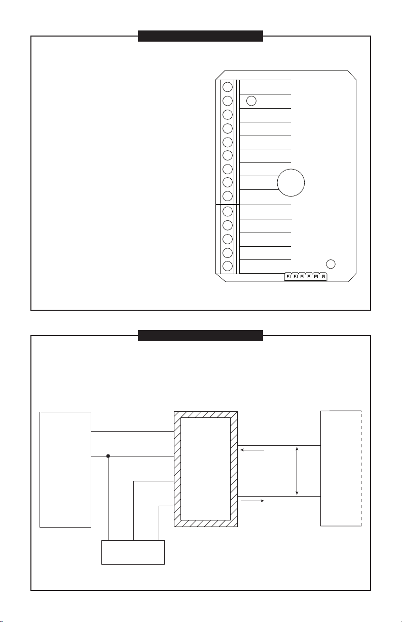
TERMINAL CONNECTIONS
Remote Transmitter INPUTS / OUTPUTS
ISO-IN COM: Return for isolated inputs
ISO-LF IN: Optically-Isolated High-level Low-frequency
Input
ISO-HF IN: Optically-Isolated High-level High-frequency
Input
HL-LF IN: High-level Low-frequency Input. 150 Hz max.
COIL-A IN: Low-level Sinewave Input
COIL-B IN: Low-level Sinewave Input
HL-HF IN: High-level High-frequency Input
EDM PWR: Local Vcc. Regulated 5-VDC internal power.
This terminal can supply up to approximately 2.5 mA,
continuously, to external circuitry. Typical load/line
regulation under ordinary conditions is about ± 10%
LOCAL COM: Local Common
0-5 V OUT: 0 to 5 V Voltage Output. Frequency to Analog
Output.
PULSE OUT: Pulse-Out Frequency Output Signal. It is an
“open-collector” output (also known as “n-p-n” or “current-sinking”), referenced to transmitter Local-Common
LOOP (–): 4 to 20 mA Current Loop – current into
transmitter
LOOP (+): 4 to 20 mA Current Loop – current out of transmitter
ISO-IN COM
ISO-LF IN
ISO-HF IN
HL-LF IN
COIL-A IN
COIL-B IN
HL-HF IN
EDM PWR
LOCAL COM
LOCAL COM
0-5 V OUT
PULSE OUT
LOOP (–)
LOOP (+)
Output: Customer Equipment, 0-20 mA Sensing, Built-in Loop Power Supply
1
OMEGA
Oval Gear
Meter
* Optional to use HL-HF IN.
2
WIRING DIAGRAM 1
— 4-20 mA or 0-20 mA Output —
Customer Equipment With Built-in Power Supply
Input: Reed Switch
INPUTS OUTPUTS
* HL-LF IN
Loop (+)
Local Com
Pulse Out
EDM Pwr
Black Blue Red
PCB Assembly
OMEGA
Remote
Transmitter
CAUTION: When reassembling the faceplate, make sure that the enclosure
seal is not crimped or twisted. Do not over-tighten corner
screws (hand tighten only). Faceplate can be rotated 90°.
(current)
Min. V = 8.5
Max. V = 35
Loop (–)
(current)
Customer
Equipment
3
Page 6
OMEGA
Oval Gear
Meter
(Hall Effect
Pickup)
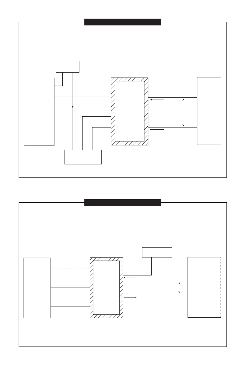
WIRING DIAGRAM 2
— 4-20 mA or 0-20 mA Output —
Customer Equipment With Built-in Power Supply
Input: Hall Effect*
Output: Customer Equipment, 0-20 mA Sensing, Built-in Loop Power Supply
HE Power Supply
4.5 - 24 VDC
(–)
(+)
1
2
3
Black Blue Red
INPUTS OUTPUTS
HL-HF IN
Local Com
Pulse Out
EDM Pwr
OMEGA
Remote
Transmitter
Loop (+)
Min. V = 8.5
Max. V = 35
Loop (–)
(current)
(current)
Customer
Equipment
PCB Assembly
* NOTE: Hall Effect requires dedicated power supply.
— 4-20 mA or 0-20 mA Output —
Customer Equipment Without Built-in Power Supply
Input: Reed Switch (see inputs from Diagram 1) or Hall Effect* (see inputs from Diagram 2)
Output: Customer Equipment, 0-20 mA Sensing, Separate Loop Power Supply
INPUTS OUTPUTS
OMEGA
Oval Gear
Meter
See Diagrams
1 & 2 for
connections
* NOTE: Hall Effect requires dedicated power supply.
CAUTION: When reassembling the faceplate, make sure that the enclosure
WIRING DIAGRAM 3
OMEGA
Remote
Transmitter
CAUTION: When reassembling the faceplate, make sure that the enclosure
seal is not crimped or twisted. Do not over-tighten corner
screws (hand tighten only). Faceplate can be rotated 90°.
Loop Power Supply
Typ 12-24 VDC
(+)
Loop (+)
(current)
Loop (–)
(current)
seal is not crimped or twisted. Do not over-tighten corner
screws (hand tighten only). Faceplate can be rotated 90°.
(–)
Min. V = 8.5
Max. V = 35
Equipment
Loop (–) Input
Loop (+) Input
Customer
4
Page 7

WIRING DIAGRAM 4
— 0-5 V Output —
Customer Equipment Without Built-in Power Supply
Input: Reed Switch (see inputs from Diagram 1) or Hall Effect* (see inputs from Diagram 2)
Output: Customer Equipment, 0-5 V Sensing, Separate Loop Power Supply
INPUTS OUTPUTS
OMEGA
Oval Gear
Meter
See Diagrams
1 & 2 for
connections
NOTE 1: Loop power supply electrically isolated
from customer equipment.
NOTE 2: Actual value of loop current (mA) is
disregarded.
* NOTE: Hall Effect requires dedicated power supply.
OMEGA
Remote
Transmitter
Loop Power Supply
Typ 12-24 VDC
(–)
Loop (+)
Loop (–)
0-5 V Output
Local Com
CAUTION: When reassembling the faceplate, make sure
(+)
(current)
(current)
that the enclosure seal is not crimped or twisted.
Do not over-tighten corner screws (hand tighten
only). Faceplate can be rotated 90°.
Customer
Equipment
0-5 V Analog
Input (+)
Analog In
Return (–)
WIRING DIAGRAM 5
— 4-20 mA or 0-20 mA Output and Pulse Output —
Customer Equipment With Built-in Power Supply
Input: Reed Switch
Output: Customer Equipment, 0-20 mA Sensing, Frequency Sensing, Built-in Loop Power Supply
INPUTS OUTPUTS
1
OMEGA
Oval Gear
Meter
Dual
Reed Switch
NOTE 1: Loop power supply electrically isolated from
NOTE 2: Actual value of loop current (mA) is disregarded.
NOTE 3: 4-20 mA and Pulse Output option available only
* Optional to use HL-HF IN.
2
3
4
customer equipment.
with Reed Switch input.
* HL-LF IN
Local Com
OMEGA
Remote
Transmitter
Loop (+)
(current)
Min. V = 8.5
Loop (–)
CAUTION: When reassembling the faceplate, make sure
Max. V = 35
(current)
that the enclosure seal is not crimped or twisted.
Do not over-tighten corner screws (hand tighten
only). Faceplate can be rotated 90°.
Customer
Equipment
Common
Open Collector
Pulse-In
5
Page 8

OPERATIONS
Computer Display
All operations are reflected in the LCD
readout. The large center digits indicate
amounts, where smaller words or “icons”
located above and below indicate specific
information regarding totals, flow, calibration
and units of measure.
Computer is on continuously and always
ready to perform. The computer is powered
by a field replaceable battery. When display
becomes dim, faded or the low battery
message appears (see below), the battery
needs to be replaced. Reference the
Maintenance Section for details.
Batch and Cumulative Totals
The computer maintains two totals. The
Cumulative Total provides continuous measurement and cannot be manually reset. The
Batch Total can be reset to measure flow
during a single use. The Cumulative Total
is labeled TOTAL 1, Batch Total is labeled
TOTAL 2 BATCH.
When the Cumulative Total reaches a
display reading of 999,999 the computer
will highlight an X10 icon. This indicates to
the operator that a zero must be added to
the 6 digits shown. When the next rollover
occurs, the computer will highlight an X100
icon. This indicates to the operator that two
zeros must be added to the 6 digits shown.
Press the DISPLAY button briefly to switch
between the TOTAL 1, TOTAL 2 BATCH
and FLOWRATE. Press DISPLAY briefly
to display the TOTAL 2 BATCH. Hold the
DISPLAY button for 3 seconds to reset the
Batch Total to zero.
When fluid is flowing through the meter, a
small propeller icon is highlighted.
NOTE: Totalization counts total units
without differentiating between gallons,
liters or field calibrated units.
Flowrate Feature
To use this feature, press and release
DISPLAY until FLOWRATE icon appears.
The factory set time base will be highlighted
to the right of FLOWRATE (M = minutes,
H = hours, D = days). When FLOWRATE
is invoked, the display will be indicating
rate of flow.
Factory and Field Calibration
All calibration information is visible to the
user as icons on the top line of the display,
above the numeric digits.
All units are configured with a “factory”
calibration. Both gallons and liters are
available (“GL” or “LT” will be displayed).
While holding the CALIBRATE button, briefly
press DISPLAY to toggle between gallons
and liters. This factory calibration (indicated
with FAC) is permanently programmed into
the computer and is not user adjustable.
NOTE: Your computer may have other units
of measure programmed into it. If so,
holding the CALIBRATE button and momentarily pressing the DISPLAY button
will toggle through all factory set units.
Other possible units are: IGL (imperial
gallon), QT (quart), CF (cubic feet), CM
(cubic meter), BL (42 gal. barrel), CC
(cubic centimeter) or OZ (ounce).
Switching between different units will not
corrupt the Total’s contents. For example,
in GL mode, the computer totalizes 10.00
gallons, if the user switches to LT mode,
the display will read 37.85 liters (the same
volume, different unit).
The “field” calibration may be set by the
user, and can be changed or modified at
any time using the calibration procedure
described in the Calibration Section. Totals
or flowrate derived from the field calibration
are invoked when the FAC icon is no longer
visible on the top line of the display.
6
Page 9

CONFIGURATION
Configuration determines what information is displayed on the screen. The configuration string is a 6-digit number that
programs the computer electronics to a
specific configuration. Using the information below, the end user can change the
information displayed on the screen by
changing the configuration string.
Remote Mount Display
The default calibration and display configuration features may not be appropriate for
the user installation.
ATTENTION
ALL remote mount and replacement
displays must be configured AND calibrated before use!
Local Mount Display
The factory calibration and display configuration features are preprogrammed and
further user programming is not required.
When replacing electronic displays, they
must be configured and calibration information entered before use. If desired, the
calibration or features can be changed in
the field using the procedures described
below.
Factory Default Configuration
The configuration strings below are the
default configurations for the local mounted
display and can be used for the final configuration for replacement displays or remote
mounted displays purchased separately.
NOTE: For replacement and remote elec-
tronics, this configuration does NOT
determine the K-factor for your specific
meter. That information must still be
entered using the calibration procedure. For replacement and remote
configurations, please see Calibration
Section for more information.
FACTORY CONFIGURATION STRINGS
MODEL FACTORY CONFIGURATION STRINGS
FPD1001
FPD1002
FPD1003
FPD1102
FPD1103
FPD1201
FPD1201-IP
FPD1202
FPD1202-HP
FPD1202-IP
FPD1203
FPD1203-HP
FPD1203-IP
FPD1004
FPD1204
FPD1105
FPD1005
FPD1205
FPD1006
FPD1007
B 2 2 0 1 3
B 1 2 0 1 3
7
Page 10

User Configuration
The flow computer has been programmed
with many features, most of which can
be enabled by the end user through the
configuration process. By disabling unnecessary features, day-to-day flowmeter
operation can be greatly simplified, making
the unit easier to use. Alternately, there are
several features available not found in the
default configuration.
User configuration features include:
• 0 to 3 totals, either resettable (batch)
or non-resettable (cumulative).
• Flowrate or no flowrate. Available in
units per minute, hour or day.
• Three different field calibration methods: K-factor entry, Dispense/Display
or % Correction Factor.
• Various units of measure (some or all):
GL (gallon), LT (liter), IGL (imperial gallon), QT (quart), CF (cubic feet), CM
(cubic meter), BL (42 gal. barrel), CC
(cubic centimeter) or OZ (ounce).
Changing Configuration Settings
Access to the co nfigu ration proc ess
requires entering the 6-digit pin code
“020748”. Configurations are entered and
stored as 6-digit codes where each digit
represents a setting for one of the configuration options. New configuration settings
are stored in the computers long-term
memory and will not be lost either in OFF
mode or during battery change.
Since there are security timeouts associated with the configuration changing process, you should determine ahead of time
what your new 6-digit configuration code
will be. Using the information below, create
the new code and write it down so that you
can refer to it during configuration.
NEW CODE CONFIGURATIONS
DIGIT 1 ENABLES
0 No Totalizing Registers
1 TOTAL 1 (Accumulative)
2 TOTAL 2 BATCH
3 TOTAL 1 & TOTAL 2 BATCH
7 TOTAL 1, TOTAL 2 BATCH & TOTAL 3 BATCH
8 Enables U.S. Gallons, No Totalization Registers
9 TOTAL 1 (Accumulative) & U.S. Gallons
A TOTAL 2 BATCH & U.S. Gallons
b TOTAL 1 & TOTAL 2 BATCH & U.S. Gallons
F TOTAL 1, TOTAL 2 BATCH & TOTAL 3 BATCH & U.S. Gallons
DIGIT 2 ENABLES
0 No Flowrate Mode
1 Flowrate in Units Per Minute
2 Flowrate in Units Per Hour
4 Flowrate in Units Per Day
8 Enables Imperial Gallons (IGL), No Flowrate Mode
9 Flowrate in Units Per Minute & Imperial Gallons Enabled
A Flowrate in Units Per Hour & Imperial Gallons Enabled
C Flowrate in Units Per Day & Imperial Gallons Enabled
8
Page 11

NEW CODE CONFIGURATIONS – CONT’D.
DIGIT 3 ENABLES
0 No Units of Measure from the below items
1 Enables Quarts (QT)
2 Enables Liters (LT)
3 Enables Quarts (QT) and Liters (LT)
4 Enables Cubic Feet (CF)
5 Enables Cubic Feet (CF) & Quarts (QT)
6 Enables Cubic Feet (CF) & Liters (LT)
7 Enables Cubic Feet (CF), Quarts (QT) & Liters (LT)
8 Enables Cubic Meters (CM)
9 Enables Cubic Meters (CM) & Quarts (QT)
A Enables Cubic Meters (CM) & Liters (LT)
b Enables Cubic Meters (CM), Quarts (QT) & Liters (LT)
C Enables Cubic Meters (CM) & Cubic Feet (QF)
d Enables Cubic Meters (CM), Cubic Feet (QF) & Quarts (QT)
E Enables Cubic Meters (CM), Cubic Feet (QF) & Liters (LT)
F Enables Cubic Meters (CM), Cubic Feet (QF), Liters (LT) & Quarts (QT)
DIGIT 4 ENABLES
0 No Units of Measure from the below items
1 Enables Barrels, 42 gallon (BL)
2 Enables Cubic Centimeter (CC)
3 Enables Barrels (BL) & Cubic Centimeters (CC)
4 Enables Ounces (OZ)
5 Enables Ounces (OZ) & Barrels (BL)
6 Enables Ounces (OZ) & Cubic Centimeters (CC)
7 Enables Ounces (OZ), Cubic Centimeters (CC) & Barrels (BL)
DIGIT 5 ENABLES
0 None of the below options enabled
1 Restore TOTAL 2 BATCH value after power loss, no filter
2 Restore TOTAL 3 BATCH value after power loss, no filter
3 Restore TOTAL 2 BATCH & TOTAL 3 BATCH values after power loss, no filter
8 Enable 8 Hertz input filter (recommended)
9 Restore TOTAL 2 BATCH value after power loss, with 8 Hz filter
A Restore TOTAL 3 BATCH value after power loss, with 8 Hz filter
b Restore TOTAL 2 BATCH & TOTAL 3 BATCH values after power loss, with 8 Hz filter
DIGIT 6 ENABLES
0 No Field Calibration allowed
1 Correction Factor method
3 K-Factor Entry method
7 Dispense/Display Entry method
9
Page 12

CONFIGURATION SETUP
Since there are security timeouts associated with the configuration changing process, you should determine ahead of time
what your new 6-digit configuration code
will be. Create the new code and write it
down so that you can refer to it before
beginning this procedure.
1. Temporarily disconnect power to the
display at any convenient point.
2. Allow at least 30 seconds before proceeding to allow all internal capacitance to discharge.
3. While the unit is still unpowered, press
and hold CAL. While holding the CAL
button, reapply power. Keep CAL button pressed for about a second after
applying power, then release.
4. While holding button, the display will
show “FLdCFG”.
5. The display should show “000000” with
the left-hand digit blinking. If you do not
see this, go back to Step 1.
6. Enter the Pin No. 020748.
a. To enter, use the CALIBRATE but-
ton to change the blinking digit
and/or use the DISPLAY button to
shift the blink to the next digit.
NOTE: You can use the buttons as
often as necessary. There is a long
timeout (about 4 minutes).
b. As an added security precaution,
if a valid password is NOT sensed,
within about 4 minutes, the computer will revert to normal operation, and you will have to repeat
the process from Step 1.
7. Briefly press and release BOTH buttons. If you have entered a valid Pin
number, the computer will immediately
display the current configuration code.
(For example: 922948). Display will
show “FLdCFG”.
NOTE: Once in configuration mode, the
computer will automatically revert to
normal operation if no button operation
is sensed for about 4 minutes.
If this happens, you have not com-
pleted the process. You will have to
repeat the entire process from Step 2.
8. Enter the 6-digit configuration code
number for your new configuration using the same method as used in Step
6a above.
9. When correctly entered, briefly press
and release BOTH buttons. The display
will briefly show “FLdCFG”, and then
the unit will return to normal operation.
Configuration is now complete.
CALIBRATION
Local Mount Display
The factory calibration and display configuration features are programmed and further
user programming is not required. When
replacing electronic displays, they must
be configured and calibration information
entered before use. If desired, the calibration or features can be changed in the field
using the procedures described below.
Remote Mount Display
The default calibration and display configuration features may not be appropriate for
the user installation.
ATTENTION
ALL remote mount and replacement
displays must be configured AND cali-
brated before use!
10
Page 13

Field Calibration
Presently all computer electronics are
programmed with two different calibration
methods, only one of which is active at
a time. K-Factor Entry calibration is the
default method. This allows a calibration
point to be entered using numerical entry
of meter K-factors.
The alternate method is Dispense/Display
which requires that a specific volume of
fluid pass through the meter to determine
the correct K-factor. Dispense/Display
calibration can be selected using computer
electronics configuration.
The specific K-factor (ppg or pulses per
gallon) of your oval gear meter is shown in
the chart below, or refer to the nameplate
on the meter.
Field Calibration Procedure
(K-Factor Entry Method)
Because the oval gear meter is positive
displacement, it requires only one K-factor
and a single point calibration is sufficient.
1. To field calibrate, press and hold the
CALIBRATE and DISPLAY buttons for
about 3 seconds until you see FLdCAL.
Release both buttons and you will see
Kxxxx.x (where “x” represents the current field-cal k-factor value). You are
now in the field calibration mode.
2. The far left digit will be blinking. The
DISPLAY button can then be pressed
to select the digit location and the
CALIBRATE button can be pressed to
scroll the desired value at the blinking
position. Edit the K-factor shown to
the desired value. Acceptable K-factor
range is 0000.1 to 9999.9.
3. After the new value has been entered,
momentarily press and release both
buttons. “CALEND” will be momentarily
displayed. Unit is now ready for use.
4. Notice that the upper display line, the
“FAC” icon and all the units of measure
have disappeared.
Alternate units of measure are not selectable when meter is operating with field
calibration. This calibration is a unique
single point calibration for the meter and/
or application.
NOTE: To return to factory calibration
(FAC), press and hold both CALIBRATION and DISPLAY buttons for about
3 seconds, until FAcCAL is displayed.
Then release buttons. Unit should
return to normal operation and FAC
icon visible.
NOTE: If the field calibration mode is
entered and NO fluid is dispensed,
then upon leaving, the computer will
use data from the last successful field
calibration.
NOTE: A Field Calibration below the
minimum flowrate can adversely effect
accuracy.
The use of a uniformly dependable, accurate calibration container is highly recommended for the most accurate results. For
the most accurate results, dispense at a
flowrate which best simulates your actual
operating conditions. Avoid “dribbling”
more fluid or repeatedly starting and stopping the flow – these actions will result in
less accurate calibrations.
Make sure you meet the meter’s minimum
flowrate requirements.
For best results, the meter should be
installed and purged of air prior to Field
Calibration.
Field Calibration Procedures
(Dispense/Display Method)
1. To field calibrate, press and hold the
CALIBRATE and DISPLAY buttons for
about 3 seconds until you see FLdCAL.
Release both buttons and you will
see dd000.0. You are now in the field
calibration mode.
2. Dispense a known amount of fluid at a
flowrate representative of the application. Any amount between .1 and 999.9
units can be used. Display will count up
while fluid is flowing through the meter.
11
Page 14

3. The DISPLAY button can then be
pushed to select the digit location and
the CALIBRATE button can be pushed
to scroll the desired value at the blinking
position. Edit the amount shown with
the value that was dispensed above.
Values from 000.1 to 999.9 can be
entered.
4. When satisfied with the value, press
both CALIBRATE and DISPLAY buttons simultaneously. CALEnd will be
displayed and unit will go back to
normal operation, less the FAC (factory
calibration) icon.
5. The meter will now be operating with
a custom calibration number unique to
the above dispense procedure. No unit
of measure (gallon, liter, etc.) icon will
be highlighted.
NOTE: To return to factory calibration (FAC),
press and hold both CALIBRATE and
DISPLAY buttons for about 3 seconds,
until FAcCAL is displayed. Then release
buttons. Unit should return to normal
operation and FAC icon visible.
NOTE: If the field calibration mode is en-
tered and NO fluid is dispensed, then
upon leaving, the computer will use data
from the last successful field calibration.
Remote Mount Display: The computer
electronics MUST be calibrated before
use. It is designed to accommodate all
oval gear meter sizes and many other
types of pulse generating devices. The
factory calibration curves are indicated
as GAL and LTR PRESET and can be
calibrated without changing the computer electronics configuration. After
the calibration of the GAL curve, the
field calibration option can be removed
using the computer electronics configuration procedure to avoid accidental
calibration.
The liter calibration is determined using the
gallon calibration information. Enter the Kfactor as pulse per gallon in the GAL curve.
This will correctly calibrate the LTR PRESET
curve. You may still remove the GAL indication on the display using the computer
electronics configuration procedure.
MODEL
FPD1001 5855.4 0.132 GPH (0.5 LPH)
FPD1201
FPD1201-IP
FPD1002 3785.4 0.53 GPH (2.0 LPH)
FPD1202
FPD1102
FPD1202-IP
FPD1202-HP
FPD1003 1514.2 4.0 GPH (15.0 LPH)
FPD1203
FPD1103
FPD1203-IP
FPD1203-HP
FPD1004 424 0.25 GPM (1.0 LPM)
FPD1204
FPD1105 197 0.8 GPM (3.0 LPM)
FPD1005 136.3 1.6 GPM (6.0 LPM)
FPD1205
FPD1006 54.9 2.6 GPM (10.0 LPM)
FPD1007 25.3 4.0 GPM (15.0 LPM)
K-FACTOR (ppg)
MINIMUM FLOWRATE FOR
DISPENSE / DISPLAY CALIBRATION
12
Page 15

Setting 4-20 mA Endpoints
The 4-20 mA endpoint settings are independent from the meter calibration. If you
reset the response time you MUST reset the
4-20 mA endpoints.
All units are shipped with the following
items preset:
• 4 mA setpoint = 50 Hz
• 20 mA setpoint = 100 Hz
• Response time = 5.2 seconds
Any new values you set for these items are
automatically saved when the transmitter is
powered down, and automatically restored
the next time power is applied.
Procedure
Before you start, the fluid pumping system
should be ready to make two simple calibrating runs, first at the lowest anticipated
flowrate, and then the second at the highest anticipated flowrate. Position yourself
so you can easily operate the transmitter’s
pushbuttons. You should be able to see the
indicator light (the small window beside the
“4” button).
Setting the Low (4 mA) Endpoint
1. Start the fluid pumping system. Set it
for steady flow at the lowest anticipated
rate (or the rate at which you want a
“minimum” indication).
2. Wait while the fluid flow is uninterrupted
for at least 10 seconds.
3. While watching the transmitter’s indicating light (to the left of the “4” button),
press and hold both its “SET” and “4”
buttons. Release them when the light
blinks.
NOTE: The length of time between “but-
ton press” and “light blink” depends
on the transmitter response time. The
maximum is 15 seconds. If you can’t see
the indicator light (if you’re outdoors in
bright light), you can safely just count to
5 while holding the pushbuttons.
NOTE: After setting the minimum, the loop
current should be registering at or near
4 mA. Don’t worry if it’s not exact, it will
be correct after setting the high (20 mA)
endpoint.
Setting the High (20 mA) Endpoint
1. Start the fluid pumping system. Set it for
steady flow at the highest anticipated
rate (or the rate at which you want a
“maximum” indication).
2. Wait while the fluid flow is uninterrupted
for at least 10 seconds.
NOTE: If you observe the current loop after
completing the procedure, it should be
registering at or very near 20 mA (within
the resolution specifications for the
present conditions).
3. While watching the transmitter’s indicating light, press and hold both its “SET”
and “20” buttons. Release them when
the light blinks.
NOTE: During the high and low setpoint
procedure, if the new settings are very
different from the previous settings, it is
possible to reverse the 4 mA and 20 mA
setpoints so that the 4 mA frequency is
higher than the 20 mA frequency. The
situation corrects itself after you complete both setpoints. If the new settings
are close to the previous settings, you
may safely set either the low and high
settings independently.
Optional 0-20 mA Mode
A few current loop systems use 0-20 mA
output. The input signal frequency of “0”
produces an output analog signal of “0” with
direct proportionality and no offset.
NOTE: A true loop current of “0” in a
loop powered device like the OMEGA
transmitter is not obtainable. That’s
because the current loop powers the
transmitter, and its operating current is
non-zero even at zero frequency input.
In 0-20 mode, the OMEGA Transmitter’s
loop current will drop to as near zero
as possible at zero input, in most units
between 1 and 2 mA.
13
Page 16

Procedure
1. To enter 0-20 mode, simply press and
hold all three pushbuttons simultaneously (4, SET, and 20) at any flowrate.
Continue holding until the indicator
light blinks (light will blink in up to 5
seconds) and release all buttons. This
sets the LOW END calibration point to
zero/zero.
2. Set the 20 mA endpoint as described
above under 4-20 mA calibration.
3. The special 0-20 mode will remain in
effect until a new 4 mA endpoint is
established in the usual way.
Auxiliary 0-5 VDC
The Transmitter is equipped with an auxiliary
voltage output with a range of 0-5 VDC. This
signal is capable of dropping to within a few
milliVolts of zero, and thus may be more
suitable for use in the 0-20 mode.
No special equipment is required to use the
0-5V output, but wiring to customer equipment is different (see Wiring Diagram 4).
Changing Response Time
The Transmitter comes from the factory with
a default 5.2 second response time. This
should provide good performance with all
OMEGA FPD Series meters.
If you reset the response time (procedure
detailed below) you MUST then reset the
4-20 mA endpoints.
To give good performance with a variety of
sensor types, many frequency-to-analog
converters, including the OMEGA Remote
Transmitter, offer two or more settings for
“response time” (sometimes referred to as
“settling time” or “averaging time”).
• Longer (slower) response times are
needed for sensor types that generate
very low frequency outputs (like FPD
Series oval gear flowmeters).
WARNING
• Operating a FPD meter at high flowrates may require a shorter (faster) response time to achieve best transmitter
performance.
• Shorter (faster) response times are preferable for sensors that generate higher
frequency outputs (OMEGA turbine
meters, for example).
• Longer (slower) response times are also
appropriate in situations where sensor
output frequency fluctuates or wobbles
substantially.
The OMEGA Remote Transmitter offers a
choice of five response time settings, selectable by the unit’s pushbuttons.
Procedure
1. Start with the transmitter unpowered.
If the transmitter is presently operating,
temporarily disable its external power
supply. Be sure to allow at least 30 seconds to elapse with unit unpowered.
2. Press and hold the “4” button. While
holding, watch the indicator light and
power up the transmitter.
3. Shortly after power is applied, the light
will blink one or more times. Count the
number of blinks (from 1 to 5 blinks) and
release the button after the blinking has
finished.
NOTE: If necessary, repeat steps 1 thru 3 to
get the number of blinks corresponding
to the response time you want.
Blinks Response Time
1 blink 0.3 second
2 blinks 0.7 second
3 blinks 1.3 second
4 blinks 2.6 second
5 blinks 5.2 second
In normal operation, the transmitter always
averages two sequential input readings.
The time delay from an abrupt change in
input frequency to a final, stabilized output
reading is always twice that shown in the
above table.
14
Page 17

MAINTENANCE
Check cable-entry sea ls periodicall y.
Tighten and/or apply sealant if needed.
This is especially important in environments
containing heavy concentrations of dust, oil
mist, or other residue.
Check all wiring connections occasionally
for oxidation or corrosion. Clean and re-seat
if such conditions are noted.
If necessary, check and re-seat any connections that may have been subjected to
strain (during rework or construction, for
example).
TROUBLESHOOTING
Symptom Probable Cause Corrective Action
A. METER IS NOT 1. Field Calibration not Field Calibrate again or select Factory
ACCURATE performed properly Calibration.
2. Factory Calibration Perform a Field Calibration according to Cali not suitable for liquid bration Section or select the proper Factory
being measured Calibration selection (i.e., gallon or liter).
3. Improper installation Check for electrical noise, pulsation or swirl
of flowmeter in the flow.
4. Flowrates too high or See section on display calibration for
too low flowrates.
B. READOUT FADED 1. Power not connected Check power supply.
OR BLANK
2. Wiring incorrect Verify connections.
3. Computer defective Contact the factory.
4. Temperature limits Check temperature specifications.
exceeded
C. NORMAL FLOW- 1. Field Calibration not Field Calibrate again or select Factory
RATE BUT METER
performed correctly Calibration.
DOES NOT COUNT
2. Computer defective Contact the factory.
3. Loose wire or mis- Check wiring diagram or cable installation.
wired
4. Sensor not attached Check continuity of sensor.
to turbine
5. Faulty sensor Contact the factory.
15
Page 18

TROUBLESHOOTING
Symptom Probable Cause Corrective Action
D. CANNOT GET 1. Factory Calibration Hold down CALIBRATE and push and release
curve active DISPLAY. Proceed with calibration according
METER INTO
to the Calibration Section.
FIELD
CALIBRATION
2. Computer circuit Replace computer. Contact the factory.
board defective
3. Wrong button Recalibrate.
sequence
4. Not holding button Hold button until the appropriate response
long enough or hard appears in the display.
enough
5. Button defective Replace computer. Contact the factory.
E. LOOP OUTPUT 1. Loop not supplying Be sure loop power supply is present and
“STUCK” AT
power working, and has correct polarity.
ZERO (No reading
2. Loop connections Check all loop connections for open- or
at all, regardless
bad short-circuits.
of input signal.)
3. Transmitter is faulty Replace transmitter.
F. LOOP OUTPUT 1. 4-20 mA setpoints Perform new setpoint procedure for both
“STUCK” AT
bad or not set 4 mA and 20 mA points.
LOW VALUE
2. No input signal Verify presence of input signal at terminal
(Between 1 and
block.
4 mA, regardless
3. Input connections Check all signal-input connections for open-
of input signal.)
bad or short-circuits.
4. Transmitter is faulty Replace transmitter.
G. LOOP OUTPUT 1. 4-20 mA setpoints Perform new setpoint procedure for both
“STUCK” AT FULL-
bad or not set 4 mA and 20 mA points.
SCALE (Above
2. Short-circuit between Check all Loop and LOCAL-COM circuitry
20 mA, regardless
Loop (-) and LOCAL- for shorts.
of input signal.)
COM circuits
H. LOOP OUTPUT 1. 4-20 mA setpoints Perform new setpoint procedure for both
WITHIN NORMAL bad or not set 4 mA and 20 mA points.
RANGE, BUT
INCORRECT
I. LOOP OUTPUT 1. Output response-time Select a longer response-time setting.
“BOUNCES” setting too short,
ERRATICALLY especially for slow
(is unstable) input signal
2. Input connections Check all signal-input connections for inter bad mittent open- or short-circuits.
16
Page 19

Symptom Probable Cause Corrective Action
2.813”
3.438”
5.750”
4.20”
1.375”
0.576”
0.328”0.250”
5.125”
2.568”
J. LOOP OUTPUT 1. Output response-time Select a shorter response-time setting.
STABLE BUT too long, especially
RESPONSE TIME for fast input signal
TOO SLOW
K. LOOP OUTPUT 1. 0-5 V output loaded Be sure 0-5 V load impedance is at least
OK, BUT 0-5 V
OUTPUT DOES
2. Wiring incorrect Verify connections.
NOT WORK
too heavily 1000 ohms (1KΩ).
DIMENSIONS
Pipe or Wall Mount
17
Page 20

DISPLAY PARTS LISTING
12
20
14
15
21
16
17
18
22
19
3
2
1
13
5
4
11
8
7
6
10
9
18
Local and Remote parts
shown in drawing.
Page 21

Item No.
No. Part No. Description Req’d.
1 120512-01 Switch Keypad Kit .....................................................................1
2 120048-01 Gasket ....................................................................................... 1
3 Computer Assembly .................................................................1
4 120043-01 PCB Assembly .......................................................................... 1
5 904005-63 Screw, 4-40 x 3/16 in. ............................................................... 2
6 901002-82 O-Ring .......................................................................................1
7 120509-01 Adapter Kit, FPD1001, FPD1201, FPD1002, FPD1202,
FPD1102, FPD1003, FPD1203 and FPD1103
(Local & Remote Models) ..................................................... 1
120509-02 Adapter Kit, FPD1004, FPD1204 and FPD1105
(Local Model) ....................................................................... 1
120509-03 Adapter Kit, FPD1005, FPD1205, FPD1006 and
FPD1007 (Local Model) ........................................................ 1
8 904006-94 Screw, Tapping, FPD1001, FPD1201, FPD1002, FPD1202,
FPD1102, FPD1003, FPD1203 and FPD1103
(Local Model) ....................................................................... 2
9 120058-01 Bracket ......................................................................................1
10 904005-13 Screw, 6-32 x 1/2 in. (Remote Model)....................................... 4
11 904002-44 Screw, 8-32 x 5/16 in. ............................................................... 2
12 125066-20 Cable, 20 ft. (Remote Model) .................................................... 1
125066-3 Cable, 100 ft. (Remote Model) .................................................. 1
13 906005-47 Threaded Plug for FPD1001, FPD1201, FPD1002,
FPD1202, FPD1102, FPD1003, FPD1203, FPD1103,
FPD1004, FPD1204 and FPD1105 (Local Model) ................1
14 902005-9 Strain Relief ............................................................................... 1
15 901002-87 O-Ring ....................................................................................... 1
16 904006-95 Screw, Hex Socket M5-0.8 x 12 (Local Model):
For: FPD1004, FPD1204 and FPD1105 ............................... 2
For: FPD1005, FPD1205, FPD1006 and FPD1007 .............. 4
17 120054-01 Main Circuit Assembly ..............................................................1
18 904005-28 Sealing Seal, 1/4-20 x 5/8 in. .................................................... 4
19 904005-74 Screw, Fillister HD, #6-32 x 3/8”, CR. ....................................... 2
20 902007-07 Strain Relief for FPD1001, FPD1201, FPD1002,
FPD1202, FPD1102, FPD1003, FPD1203, FPD1103,
FPD1004, FPD1204 and FPD1105 with English
Fittings (Remote Model) ....................................................... 1
21 906005-48 Seal for FPD1001, FPD1201, FPD1002, FPD1202,
FPD1102, FPD1003, FPD1203, FPD1103,
FPD1004, FPD1204 and FPD1105 (Local Model) ................1
22 90400811 Washer, Flat, #6 (Type B), Narrow, SS....................................... 2
19
Page 22

LOCAL MODEL
SPECIFICATIONS
Applications:
Use for indoor or outdoor applications
where occasional moisture is common.
Materials:
Acetal, Amorphous Nylon, Silicone Rubber, Polyester (decals), FKM (gasket &
seals), Stainless Steel (fasteners)
Power Source:
External Loop powered, 8.5 - 35 VDC,
35 mA (max.)
Output:
Frequency to current conversions
Frequency to voltage
Configuration:
2-Totals (1 cumulative and 1 batch),
Rate, 2 Cals (Factory calibration in gallons or liters; 1 field calibration), K-factor
to match published K-factor for each
size meter.
Input Signal:
Hall Effect or Reed Switch
Time Base:
Hours for FPD1000 Series Low Flow
Minutes for FPD1000 Series High Flow
Unit of Measure:
U.S. gallons or liters
Accuracy:
No additional error over coupled flow
meter’s accuracy
Frequency Range:
0.25 to 1000 hertz
Batch Total:
Up to 999,999 (x100)
Cumulative Total:
Up to 999,999 (x100)
Temperature:
0° F to +140° F (–18° C to +60° C)
Cable:
No cable provided
Mechanical Connections:
Display is mounted directly to flow meter
body.
Electrical Connections:
Two strain relief ports: PG7 (1/2-20)
thread; Grip range: .11 to .26 inches
Dimensions (transmitter only):
FPD1000 Series Low Flow: Width: 4.5 in.
(11.4 cm), Height: 6 in. (15.2 cm), Depth:
4.5 in. (11.4 cm)
All other models: Widths: 4.5 in. (11.4
cm), Height: 4.5 in. (11.4 cm), Depth:
2.5 in. (6.4 cm)
Shipping Weight:
1.1 lb. (.5 kg)
20
Page 23

REMOTE MODEL
SPECIFICATIONS
Applications:
Use for indoor or outdoor applications
where occasional moisture is common.
Materials:
Acetal, Amorphous Nylon, Silicone Rubber, Polyester (decals), FKM (gasket &
seals), Stainless Steel (fasteners), PVC
(cable jacket)
Power Source:
External Loop powered, 8.5 - 35 VDC,
35 mA (max.)
Output:
Frequency to current conversions
Frequency to voltage
Configuration:
2-Totals (1 cumulative and 1 batch),
Rate, 2 Cals (Factory calibration in gallons or liters; 1 field calibration), K-factor
must be programed for each size meter.
Input Signal:
NPN Open-collector, Hall Effect, Reed
Switch or Sine Wave.
Time Base:
Hours for FPD1000 Series Low Flow
and High Pressure
Minutes for FPD1000 Series High Flow
Unit of Measure:
U.S. gallons or liters
Accuracy:
No additional error over coupled flow
meter’s accuracy.
Frequency Range:
0 to 750 hertz
Batch Total:
Up to 999,999 (x100)
Cumulative Total:
Up to 999,999 (x100)
Temperature:
0° F to +140° F (–18° C to +60° C)
Cable:
20 feet, 3-conductor (red, black & white),
tinned drain wire, 22 AWG, PVC jacket
.212 dia., (Reference Belden 9363 or
equivalent cable).
Mechanical Connections:
Wall or pipe mountable with standard
U-bolts.
Electrical Connections:
Two strain relief ports: PG7 (1/2-20)
thread; Grip range: .11 to .26 inches
1 additional strain relief required on the
flow meter.
Dimensions:
Width: 4.5 in. (11.4 cm)
Height: 6 in. (15.2 cm)
Depth: 2.5 in. (6.4 cm)
Shipping Weight:
1.1 lb. (.5 kg)
Frequency Inputs (Remote Display):
Low Level Coil (LLC): Frequency Range
0-1000 Hz (waveform dependent)
High-Level Low Frequency (HLLF):
Frequency Range 0-150 Hz (de bounced, waveform dependent)
High Level High Frequency (HLHF):
Frequency Range 0-1200 Hz (not
debounced, requires clean logic level
square or rectangular waveform)
Optically isolated HLLF: Same as HLLF
with 2500 V optical isolation
Optically isolated HLHF: Same as HLHF
with 2500 V optical isolation
NOTE: OMEGA FPD Series Meter Sen-
sors use High Level Low Frequency
(HLLF) input.
21
Page 24

Frequency Inputs (Remote Display):
Low Level Coil (LLC): Frequency Range
0-1000 Hz (waveform dependent)
High-Level Low Frequency (HLLF):
Frequency Range 0-150 Hz (de bounced, waveform dependent)
High Level High Frequency (HLHF):
Frequency Range 0-1200 Hz (not
debounced, requires clean logic level
square or rectangular waveform)
Optically isolated HLLF: Same as HLLF
with 2500 V optical isolation
Optically isolated HLHF: Same as HLHF
with 2500 V optical isolation
NOTE: OMEGA FPD Series Meter Sen-
sors use High Level Low Frequency
(HLLF) input.
Performance:
Max. Conversion Error: (nonlinearity plus
span, any input, loop-current output,
0°C to 70°C, loop voltage supply
12 VDC to 24 VDC) 0.5% of span plus
possible resolution uncertainty.
Max. Conversion-Resolution
Uncertainty: (Loop-current output, when
properly calibrated) Larger of 0.1 mA
or [20mA / (10 x ( f20–f4)].
Where f20 = frequency at 20mA,
f4 = frequency at 4mA.
Speed of Response: After step change
in input frequency, loop output
guaranteed stable within 3 x accu mulating-time (Accumulating-time
user selectable from 0.3 sec,
0.7 sec, 1.3 sec, 2.6 sec, 5.2 sec)
22
Page 25

Page 26

Page 27

25
Page 28

M-4 127 / 1010
 Loading...