

Page 1
Flow 6.25 GPM
Total 1234567.8>
IS O9002
CERTIFIED
CORPORATE QUALITY
MANCHESTER, UK
ISO 9001
CERTIFIED
CORPORATE QUALITY
STAMFORD, CT
User’s Guide
Shop online at
www.omega.com
e-mail: info@omega.com
FP90 SERIES
Flow Transmitters
Page 2

OMEGAnet® Online Service Internet e-mail
www.omega.com info@omega.com
Servicing North America:
USA: One Omega Drive, P.O. Box 4047
ISO 9001 Certifi ed Stamford CT 06907-0047
TEL: (203) 359-1660 FAX: (203) 359-7700
e-mail: info@omega.com
Canada: 976 Bergar
Laval (Quebec) H7L 5A1
TEL: (514) 856-6928 FAX: (514) 856-6886
e-mail: info@omega.ca
For immediate technical or application assistance:
USA and Canada: Sales Service: 1-800-826-6342 / 1-800-TC-OMEGA
Customer Service: 1-800-622-2378 / 1-800-622-BEST
Engineering Service: 1-800-872-9436 / 1-800-USA-WHEN
TELEX: 996404 EASYLINK: 62968934 CABLE: OMEGA
Mexico: En Español: (001) 203-359-7803 e-mail: espanol@omega.com
FAX: (001) 203-359-7807 info@omega.com.mx
Servicing Europe:
Benelux: Postbus 8034, 1180 LA Amstelveen, The Netherlands
TEL: +31 (0)20 3472121 FAX: +31 (0)20 6434643
Toll Free in Benelux: 0800 0993344
e-mail: sales@omegaeng.nl
Czech Republic: Rudé arm
TEL: +420 (0)59 6311899 FAX: +420 (0)59 6311114
Toll Free: 0800-1-66342 e-mail: info@omegashop.cz
France: 11, rue Jacques Cartier, 78280 Guyancourt, France
TEL: +33 (0)1 61 37 29 00 FAX: +33 (0)1 30 57 54 27
Toll Free in France: 0800 466 342
e-mail: sales@omega.fr
Germany/Austria: Daimlerstrasse 26, D-75392 Deckenpfronn, Germany
TEL: +49 (0)7056 9398-0 FAX: +49 (0)7056 9398-29
Toll Free in Germany: 0800 639 7678
e-mail: info@omega.de
United Kingdom: One Omega Drive, River Bend Technology Centre
ISO 9002 Certifi ed Northbank, Irlam, Manchester
M44 5BD United Kingdom
TEL: +44 (0)161 777 6611 FAX: +44 (0)161 777 6622
Toll Free in United Kingdom: 0800-488-48
e-mail: sales@omega.co.uk
.
dy 1868, 733 01 Karvin. 8
®
®
®
It is the policy of OMEGA to comply with all worldwide safety and EMC/EMI regulations that apply.
OMEGA is constantly pursuing certifi cation of its products to the European New Approach Directives.
OMEGA will add the CE mark to every appropriate device upon certifi cation.
The information contained in this document is believed to be correct, but OMEGA Engineering, Inc. accepts
no liability for any errors it contains, and reserves the right to alter specifi cations without notice.
WARNING: These products are not designed for use in, and should not be used for, patient-connected applications.
OMEGA FP90 Series Flow Transmitter Instructions
Page 3
Omega FP90 Series Flow Transmitter Instructions
Flow 6.25 GPM
Total 1234567.8>
• Remove power to unit before wiring input and
output connections.
• Follow instructions carefully to avoid personal
injury.
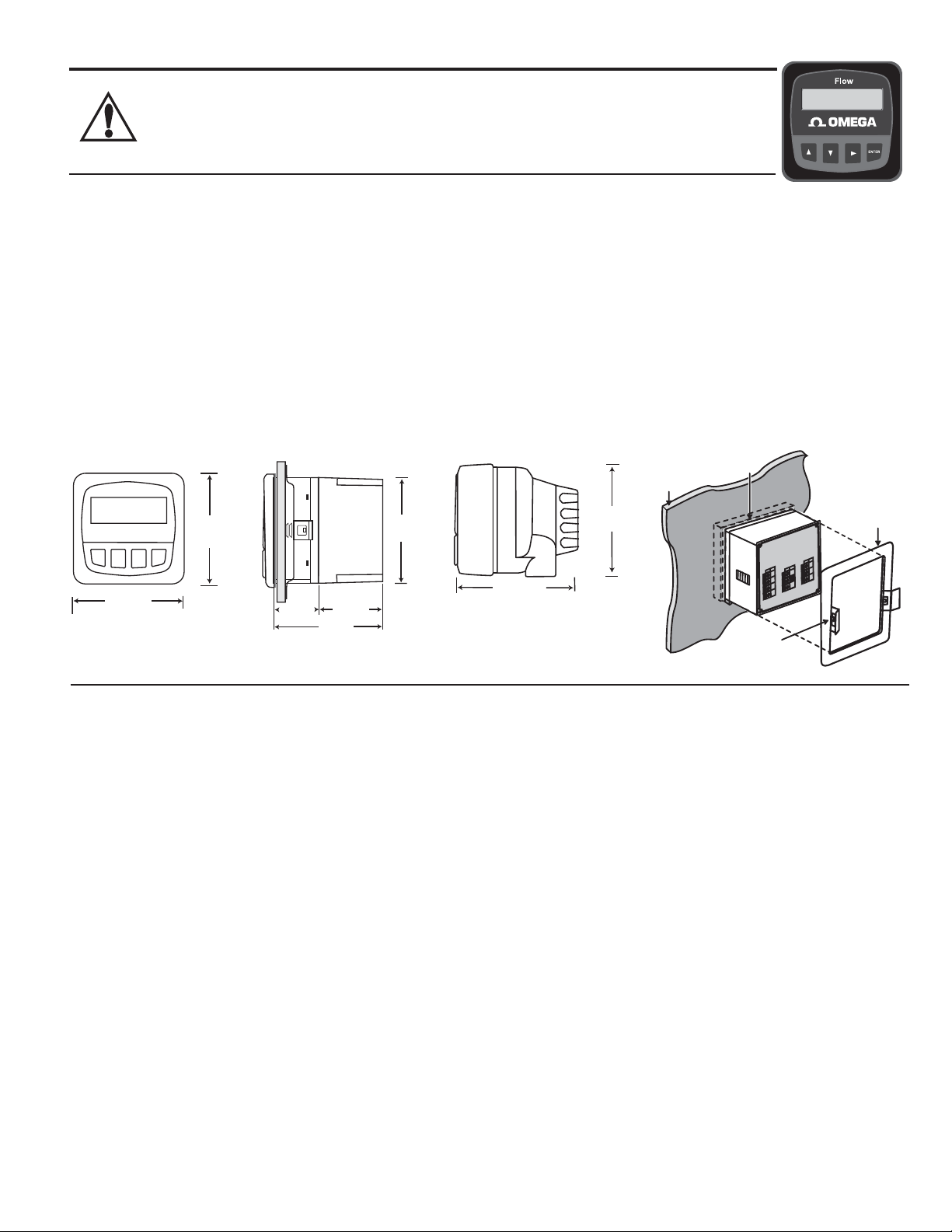
Installation
FP90 series transmitters are available in two styles: panel mount and fi eld mount. The panel mount is supplied with the necessary
hardware to install the transmitter. This manual includes complete panel mounting instructions.
Field mounting requires one of two separate mounting kits. The FP90IM integral kit joins the sensor and instrument together into a
single package. The FP90UM Universal kit enables the transmitter to be installed virtually anywhere.
Detailed instructions for integral mounting or other fi eld installation options are included with the FP90IM Integral kit or the
FP90UM Universal kit.
Panel Installation
1. The panel mount transmitter is designed for installation using a 1/4 DIN Punch. For manual panel cutout, an adhesive
template is provided as an installation guide. Recommended clearance on all sides between instruments is 1 inch.
2. Place gasket on instrument, and install in panel.
3. Slide mounting bracket over back of instrument until quick-clips snap into latches on side of instrument.
4. To remove, secure instrument temporarily with tape from front or grip from rear of instrument. DO NOT RELEASE.
Press quick-clips outward and remove.
96 mm
(3.8 in.)
FRONT VIEW
Field Mount &
Panel Mount
96 mm
(3.8 in.)
41 mm
(1.6 in.
)
SIDE VIEW
Panel Mount
Optional
Rear
Cover
56 mm
(2.2 in.)
97 mm
(3.8 in.)
92 mm
(3.6 in.)
Specifi cations
General
Accuracy: ±0.5 Hz
Enclosure:
• Rating: NEMA 4X/IP65 front
• Case: PBT
• Panel case gasket: Neoprene
• Window: Polyurethane coated polycarbonate
• Keypad: Sealed 4-key silicone rubber
• Weight: Approx. 325g (12 oz.)
Display:
• Alphanumeric 2 x 16 LCD
• Update rate: 1 second
• Contrast: User selected, 5 levels
• Thermal sensitivity shift: ±0.005% of reading per °C
Electrical
• Power: 12 to 24 VDC ±10%, regulated,
21 mA max current
Sensor Input:
• Range: 0.5 to 1500 Hz
• Sensor power: 2-wire: 1.5 mA @ 5 VDC ± 1%
3 or 4 wire: 20 mA @ 5 VDC ± 1%
• Optically isolated from current loop
• Short circuit protected
Current output:
• 4 to 20 mA, isolated, fully adjustable and reversible
• Max loop impedance: 50 Ω max. @ 12 V
325 Ω max. @ 18 V
600 Ω max. @ 24V
OMEGA FP90 Series Flow Transmitter Instructions
Contents
1. Installation
2. Specifi cations
3. Electrical Connections
4. Menu Functions
gasket on
front side
panel
96 mm
(3.8 in.)
102 mm
(4.0 in.)
SIDE VIEW
Field Mount w/
Integral kit
• Update rate: 100 ms
• Loop accuracy: ±0.03 mA
Open-collector output: Hi, Lo, Frequency, Pulse Programmable
• Optically isolated, 50 mA max. sink, 30 VDC max. pull-up
voltage.
• Maximum pulse rate: 300 pulses per minute
• Hysteresis: Adjustable
Relay outputs (2 sets mechanical SPDT contacts):
• Hi, Lo, Frequency, Pulse Programmable (300 pulses/min max)
• Maximum voltage rating: 5 A @ 30 VDC, 5 A @ 250 VAC
resistive load
• Hysteresis: User adjustable
Environmental
• Operating temperature: -10 to 70°C (14 to 158°F)
• Storage temperature: -15 to 80°C (5 to 176°F)
• Relative humidity: 0 to 95%, non-condensing
• Maximum altitude: 2000 m (6562 ft)
• Insulation category: II
• Pollution degree: 2
Standards and Approvals
• CE
• Immunity: EN50082-2
• Emissions: EN55011
• Safety: EN61010
• Manufactured under ISO 9001 and ISO 14001
of panel
quick-clip
mounting
9
8
6
4
7
3
5
2
1
bracket
page 1
Page 4
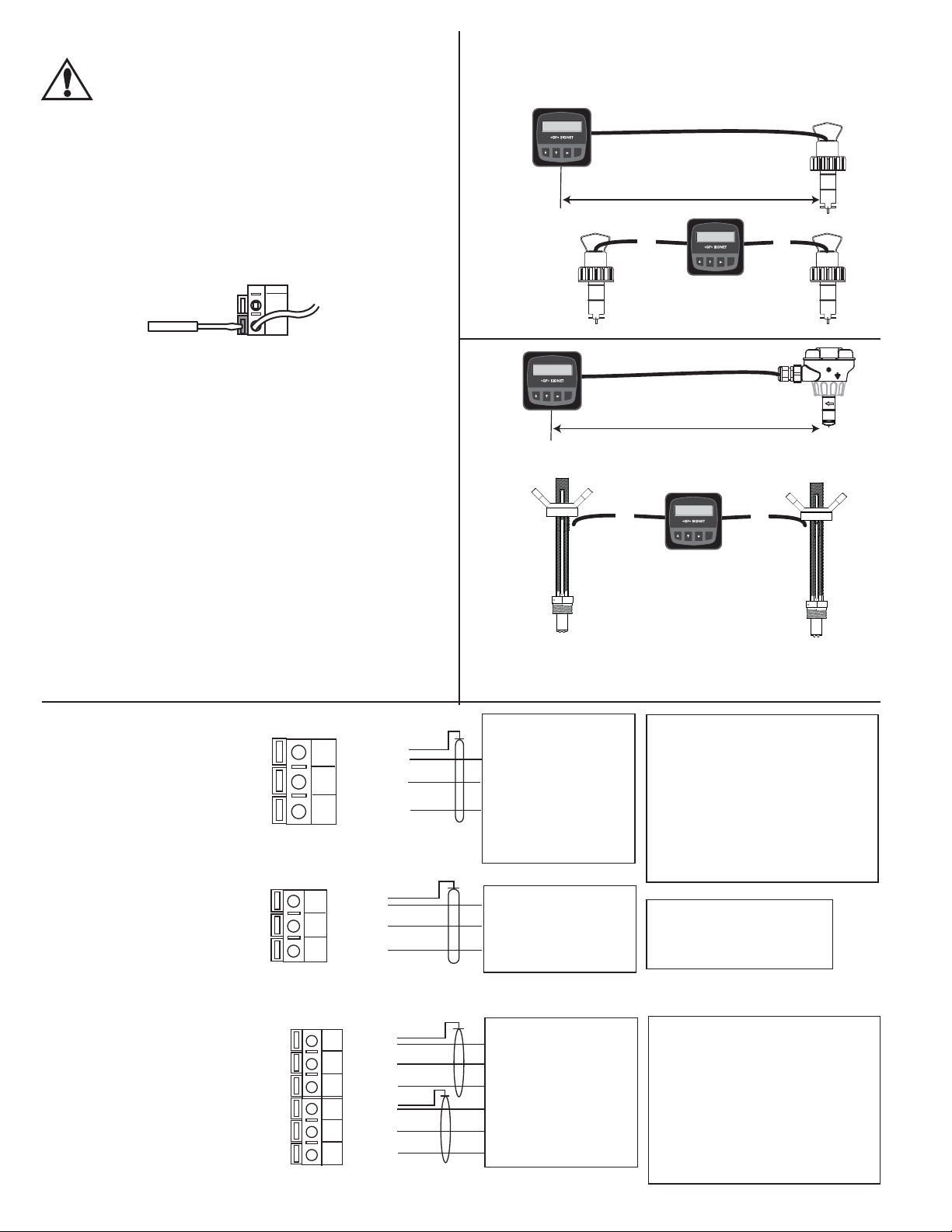
Electrical Connections
Caution: Failure to fully open terminal jaws before
removing wire may permanently damage instrument.
Wiring Procedure
1. Remove 0.5 - 0.625 in. (13-16 mm) of insulation from wire
end.
2. Press the orange terminal lever downward with a small
screwdriver to open terminal jaws.
3. Insert exposed (non-insulated) wire end in terminal hole
until it bottoms out.
4. Release orange terminal lever to secure wire in place.
Gently pull on each wire to ensure a good connection.
Maximum cable length is 200 ft. for FP5100, FP5200, FP5300,
FP6000 and any sinusoidal fl ow signal.
FP90-1, -2
Flow
Flow 6.25 GPM
Total 1234567.8>
ENTER
≤ 200 ft. (61 m)
FP90-3
Flow
Flow1: 6.25 GPM
B
Flow2: 9.75 GPM
ENTER
A
2
1
Wiring Removal Procedure
1. Press the orange terminal lever downward with a small
screwdriver to open terminal jaws.
2. When fully open, remove wire from terminal.
Wiring Tips:
• Do not route sensor cable in conduit containing AC power
wiring. Electrical noise may interfere with sensor signal.
• Routing sensor cable in grounded metal conduit will help
prevent electrical noise and mechanical damage.
• Seal cable entry points to prevent moisture damage.
• Only one wire should be inserted into a terminal. Splice
double wires outside the terminal.
Sensor Input Connections
FP90-1 Terminals
Sensr Gnd
9
(SHIELD)
Sensr IN
8
(RED)
Sensr V+
7
(BLACK)
FP90-2 Terminals
Sensr Gnd
13
(SHIELD)
Sensr IN
12
(RED)
Sensr V+
11
(BLACK)
A ≤ 200 ft. (61 m)
B
≤ 200 ft. (61 m)
FP90-1, -2
Flow
Flow 6.25 GPM
Total 1234567.8>
ENTER
≤ 1000 ft. (300 m)
FP90-3
Flow
Flow1: 6.25 GPM
B
Flow2: 9.75 GPM
ENTER
A
A ≤ 1000 ft. (305 m)
B
≤
1000 ft. (305 m)
Maximum cable length is 1000 ft. for FP-5600/FP8501,FP2540/
FP3-1500, FMG-3000 and FMG-550 and any square wave fl ow
signal.
No Aux Power:
FP-5100
FP-5200
FP-5300
FP-6000
FP-8500
FP-8501
Aux Power for FP90-1:
FP-5060
FP-5600
FP-8500A
FP-8501A
FP-2541
FMG-3000 Series Magmeter
FMG-550 Series magmeter
Any Open Collector pulse input
All sensors
Aux Power for FP90-2 must
always be connected to
provide relay power.
page 2
FP90-3 Terminals
Snsr 2 Gnd
16
(SHIELD)
Snsr 2 IN
15
(RED)
Snsr 2 V+
14
(BLACK)
Snsr 1 Gnd
13
(SHIELD)
Snsr 1 IN
12
(RED)
Snsr 1 V+
11
(BLACK)
No Aux Power:
FP-5100
FP-5200
FP-5300
FP-6000
FP-8500
FP-8501
Aux Power for FP90-3:
FP-5060
FP-5600
FP-8500A
FP-8501A
FP-2541
FMG-3000 Series Magmeter
FMG-550 Series magmeter
Any Open Collector pulse input
OMEGA FP90 Series Flow Transmitter Instructions
Page 5
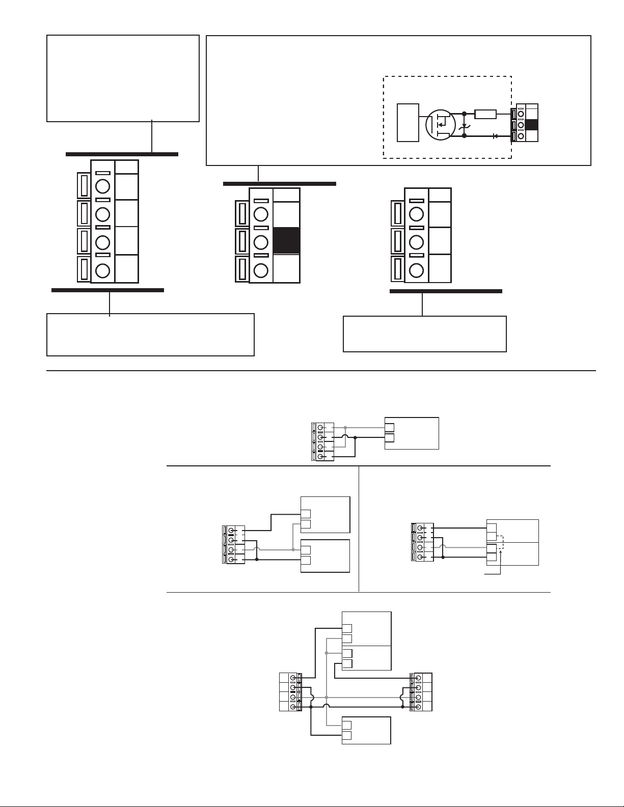
FP90-1 rear terminals
Internal open-collector
output circuit
Output --
Output +
Isolation
15Ω
S
D
Terminals 3 and 4: Loop Power
12-24 VDC ±10% system power
and current loop output.
Max. loop impedence:
50 Ω max. @ 12 V
325 Ω max. @ 18 V
Terminals 5 and 6: Open-collector Output
A transistor output, programmable (see CALIBRATE menu) as:
• High or Low with adjustable hysteresis
• Volumetric pulse
• Frequency based on fl ow rate
• May be disabled (Off) if not used.
600 Ω max. @ 24 V
System Pwr
4
Loop -
System Pwr
3
Loop +
AUX
2
Power -
AUX
1
Power +
Terminals 1 and 2: AUXILIARY power
12-24 VDC ±10% Used only if the fl ow sensor
requires more than 1.5 mA current.
6
5
Output -
Output +
Sensr Gnd
9
(SHIELD)
Sensr IN
8
(RED)
Sensr V+
7
(BLACK)
Terminals 7-9: Flow sensor input
See next page for more information.
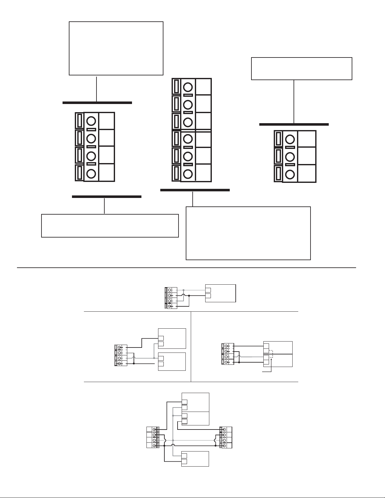
FP90-1 System Power/Loop Connections
Stand-alone application, no current loop used
System Pwr Loop -
System Pwr Loop +
AUX Power -
* See AUX POWER Note
Connection to a PLC/Recorder, separate supply
Transmitter
Terminals
System Pwr Loop -
System Pwr Loop +
AUX Power -
AUX Power +
* See AUX POWER Note * See AUX POWER Note
Example: Two transmitters connected to PLC/Recorder with separate power supply
Auxiliary Power note:
AUXILIARY power is used only if the flow sensor requires more than 1.5 mA current.
4
4
3
3
2
2
1
1
System Pwr Loop -
System Pwr Loop +
AUX Power -
AUX Power +
AUX Power +
Transmitter 1
Terminals
4
3
2
1
Transmitter
Terminals
4
4
3
3
2
2
1
1
PLC or Recorder
+
Loop Input
4-20 mA
-
Power
-
Supply
12-24 VDC
+
+
Connection to a PLC with built-in power supply
System Pwr Loop -
System Pwr Loop +
AUX Power -
AUX Power +
PLC or Recorder
+
Channel 1
4-20 mA in
-
-
Channel 2
4-20 mA in
+
Power
-
Supply
12-24 VDC
+
Power
Supply
12-24 VDC
Transmitter
Terminals
4
4
3
3
2
2
1
1
PLC
Transmitter 2
Terminals
4
System Pwr Loop -
4
3
System Pwr Loop +
3
2
AUX Power -
2
1
AUX Power +
1
* See AUX POWER Note
Internal
Connection
PLC Terminals
Loop Input
+
4-20 mA
-
Power
-
Supply
+
12-24 VDC
OMEGA FP90 Series Flow Transmitter Instructions
page 3
Page 6
FP90-2 Wiring
Terminals 3 and 4: Loop Power
12-24 VDC ±10% system power
and current loop output.
Max. loop impedance:
50 Ω max. @ 12 V
325 Ω max. @ 18 V
600 Ω max. @ 24 V
10
9
Terminals 11-13: Flow sensor input
See next page for more information.
Relay 2
(NO)
Relay 2
(COM)
System Pwr
4
Loop -
System Pwr
3
Loop +
AUX
2
Power -
AUX
Power +
1
Terminals 1 and 2: AUXILIARY power
12-24 VDC ±10% provides power for relay operation.
Stand-alone application, no current loop used
System Pwr Loop -
System Pwr Loop +
AUX Power -
* See AUX POWER Note
AUX Power +
Transmitter
Terminals
Relay 2
8
(NC)
Relay 1
7
(NO)
Relay 1
6
(COM)
Relay 1
5
(NC)
Terminals 5-10: Relay Outputs
Two sets mechanical SPDT contacts,
programmable (see CALIBRATE menu) as:
• High or Low with adjustable hysteresis
• Volumetric pulse based on totalizer
• May be disabled (Off) if not used.
4
4
3
3
2
2
1
1
+
Power
Supply
12-24 VDC
13
12
11
Sensr Gnd
(SHIELD)
Sensr IN
(RED)
Sensr V+
(BLACK)
page 4
Connection to a PLC/Recorder, separate supply
Transmitter 1
Terminals
4
3
2
1
PLC or Recorder
+
Loop Input
4-20 mA
-
Power
-
Supply
12-24 VDC
+
Transmitter
Terminals
System Pwr Loop -
System Pwr Loop +
AUX Power -
AUX Power +
* See AUX POWER Note
Example: Two transmitters connected to PLC/Recorder with separate power supply
Auxiliary Power note:
• AUXILIARY Power is required for all systems where relays are used.
4
4
3
3
2
2
1
1
System Pwr Loop -
System Pwr Loop +
AUX Power -
AUX Power +
Connection to a PLC with built-in power supply
Transmitter
AUX Power -
AUX Power +
Transmitter 2
Terminals
Terminals
* See AUX POWER Note
System Pwr Loop -
System Pwr Loop +
* See AUX POWER Note
PLC or Recorder
+
Channel 1
4-20 mA in
-
-
Channel 2
4-20 mA in
+
Power
-
Supply
12-24 VDC
+
PLC Terminals
4
4
3
3
2
2
1
1
PLC
4
System Pwr Loop -
4
3
System Pwr Loop +
3
2
AUX Power -
2
1
AUX Power +
1
Internal
Connection
+
-
+
Loop Input
4-20 mA
Power
Supply
12Ð24 VDC
OMEGA FP90 Series Flow Transmitter Instructions
Page 7

1
Internal open-collector
output circuit
Outputs
Isolation
15Ω
S
D
2
_
+
FP90-3 Wiring
Terminals 3-6: Loop Power
12-24 VDC ±10% system power
and current loop outputs.
Max. loop impedance:
50 Ω max. @ 12 V
325 Ω max. @ 18 V
600 Ω max. @ 24 V
Terminals 7-10: Open-collector Outputs
Two transistor outputs, programmable (see CALIBRATE menu) as:
• High or Low with adjustable hysteresis
• Pulse based on Volume.
• Frequency based on fl ow rate
• May be disabled (Off) if not used.
Loop 2-
6
Loop 2+
5
System Pwr
4
Loop -
System Pwr
3
Loop +
AUX
2
Power -
AUX
1
Power +
10
9
8
7
Terminals 1 and 2: AUXILIARY power
Used only if the fl ow sensor requires more than 1.5 mA current.
Refer to your fl ow sensor specifi cations for this information.
Stand-alone application, no current loop used
System Power Loop 1 –
System Power Loop 1 +
Loop 2 –
Loop 2 +
AUX Power –
AUX Power +
Tra ns mitter
Terminals
6
5
4
3
2
1
NC
NC
Output 2-
Output 2+
Output 1-
Output 1+
Power
–
Supply
+
12–24 VDC
Snsr 2 Gnd
16
(SHIELD)
Snsr 2 IN
15
(RED)
Snsr 2 V+
14
(BLACK)
Snsr 1 Gnd
13
(SHIELD)
Snsr 1 IN
12
(RED)
Snsr 1 V+
11
(BLACK)
Terminals 11-16: Flow sensor inputs
See Sensor Input section for more information.
OMEGA FP90 Series Flow Transmitter Instructions
Connection to a PLC/Recorder , separate supply
Tra ns mitter
Terminals
Loop 2 –
Loop 2 +
System Power Loop 1 –
System Power Loop 1 +
AUX Power –
AUX Power +
Example: T wo transmitters connected to PLC/Recorder with separate power supply
System Power Loop 1 –
System Power Loop 1 +
6
5
4
3
2
1
Loop 2 –
Loop 2 +
AUX Power –
AUX Power +
Tra nsm itter 1
Terminals
6
5
4
3
2
1
PLC or R ecorder
+
Channel 2
4-20 mA
–
Channel 1
–
4-20 mA
+
Power
–
Su pply
+
12–24 VDC
Auxiliary Power Note:
Auxiliary power is necessary for flow sensors that require more than 1.5 mA of current.
Connection to a PLC with built-in power supply
System Power Loop 1 –
System Power Loop 1 +
AUX Power –
AUX Power +
PLC or R ecorder
+
Channel 1
4-20 mA in
–
+
Channel 2
4-20 mA in
–
–
Channel 3
4-20 mA in
+
–
Channel 4
4-20 mA in
+
Power
–
Supply
+
12–24 VDC
Loop 2 –
Loop 2 +
Tra ns mitter
Terminals
6
5
4
3
2
1
Tra nsm itter 2
Terminals
Internal
Connection
PLC
Loop 2 –
6
Loop 2 +
5
System Power Loop 1 –
4
System Power Loop 1 +
3
AUX Power –
2
AUX Power +
1
PLC Terminals
Channel 2
+
4-20 mA
–
Channel 1
+
4-20 mA
–
Power
–
Supply
+
12–24 VD C
page 5
Page 8

Hysteresis
Time
Low Setpoint
Process
Relay energized
Relay deenergized
Hysteresis
Time
High Setpoint
Process
Open Collector and Relay Outputs
Flow 6.25 GPM
Total 1234567.8>
The open collector and relay outputs can be used as a switch that
responds when the fl ow rate moves above or below a setpoint,
or it can be used to generate a pulse that is relative to the fl ow
volume or to the fl ow rate.
Low (Open Collector or Relay output)
Output triggers when the fl ow rate is less than the setpoint.
The output will deenergize when the fl ow rate moves above the
setpoint plus the hysteresis value.
High (Open Collector or Relay output)
Output triggers when the fl ow rate is greater than the setpoint.
The output will deenergize when the fl ow rate drops below the
setpoint plus the hysteresis value.
Frequency (Open Collector only)
Output is a pulse stream that is based on the input fl ow sensor
signal. The input frequency can be divided by any value from 1 to
254.
Pulse (Open Collector or Relay output)
Output is a pulse based on the volume of fl uid that passes the
sensor. Set any value from 0.0001 to 99999.
VIEW menus
• During normal operation, the FP90 displays the VIEW menu.
• When using the CALIBRATE or OPTIONS menus, the FP90 will return to the VIEW menu if no activity occurs for 10 minutes.
• To select the item you want displayed, press the UP or DOWN arrow keys. The items will scroll in a continuous loop. Changing the
display selection does not interrupt system operations.
• No key code is necessary to change display selection.
• Output settings cannot be edited from the VIEW menu.
View Menu for FP90-1
Display Description
Monitor the fl ow rate and the resettable totalizer. Press the RIGHT ARROW key to reset
the totalizer. If the totalizer is locked, you will need to enter the Key Code fi rst.
Lock or Unlock the totalizer in the OPTIONS menu.
This is the permanent View display.
Monitor the Permanent Totalizer value.
Monitor the 4-20 mA Loop output.
Monitor date for scheduled maintenance or date of last calibration.
0.0 GPM
Total: 12345678 >
All of the displays below are temporary. After ten minutes the display will return to the permanent display.
Perm: 12345678
Gallons
Loop Output:
12.00 mA
Last CAL:
6-16-09
page 6
OMEGA FP90 Series Flow Transmitter Instructions
Page 9

View Menu for FP90-2
Display Description
0.0 GPM
Total: 12345678 >
Monitor the fl ow rate and the resettable totalizer. Press the RIGHT ARROW key to reset
the totalizer. If the Reset is locked, you will need to enter the Key Code fi rst. Lock or
Unlock the totalizer in the OPTIONS menu. This is the permanent View display.
All of the displays below are temporary. After ten minutes the display will return to the permanent display.
Perm: 12345678
Gallons
Loop Output:
12.00 mA
Last CAL:
6-16-09
Monitor the Permanent Totalizer value.
Monitor the 4-20 mA Loop output.
Monitor date for scheduled maintenance or date of last calibration.
View Menu for FP90-3
Display Description
Flow1: 123.4 GPM
Flow2: 567.8 GPM
Delta Flow:
10.5 GPM
All of the VIEW displays below are temporary.
The permanent display will return after ten minutes.
Tot1: 1234567.8
Tot2: 123456.78 >
Perm1: 1234567.8
Gallons
Perm2: 123456.78
Gallons
Loop 1 Output:
12.00 mA
Loop 2 Output:
12.00 mA
Last CAL
6-16-09
Monitor the fl ow rate of Channel 1 and Channel 2 simultaneously.
This is a permanent display.
Monitor the delta fl ow rate (Channel 1 rate - channel 2 rate = Delta Flow)
This is a permanent display.
Monitor channel 1 and channel 2 Resettable Totalizers. Press the RIGHT ARROW key to
reset the totalizer. If Reset is locked, you must enter Key Code. Lock or Unlock function is
in OPTIONS menu.
Monitor channel 1 Permanent Totalizer.
Monitor channel 2 Permanent Totalizer.
Monitor the 4-20 mA Loop 1 output.
Monitor the 4-20 mA Loop 2 output.
Monitor date for scheduled maintenance or date of last calibration.
OMEGA FP90 Series Flow Transmitter Instructions
page 7
Page 10

FP90 series Editing Procedure:
OPTIONS
CALIBRATE
VIEW
2s 5s
Press &
hold for
access:
ENTER
20.0 G
Output Setpnt:
2
0.00 GPM
Output Setpnt:
1
0.00 GPM
ENTER
Output
Setpnt:
1
0
.00
GPM
Output Setpnt:
1
9
.00 GPM
Output Setpnt:
Saving
Output
Setpnt:
19.00 GPM >
20.0 GPM >
Output Setpnt:
GPM >
Flow Units:
CALIBRATE: ----
Enter Key Code
CALIBRATE: *---
Enter Key Code
CALIBRATE: **-Enter Key Code
CALIBRATE: ***Enter Key Code
GPM >
Flow Units:
Step 1. Press and hold ENTER key:
• 2 seconds to select the CALIBRATE menu
• 5 seconds to select the OPTIONS menu.
Step 2. The Key Code is UP-UP-UP-DOWN keys in sequence.
• After entering the Key Code, the display will show the fi rst item in the selected menu.
Step 3. Scroll menu with UP or DOWN arrow keys.
Step 4. Press RIGHT ARROW key to select menu item to be edited.
• The fi rst display element will begin fl ashing.
Step 5. Press UP or DOWN keys to edit the fl ashing element.
• RIGHT ARROW key advances the fl ashing element.
Step 6. Press ENTER key to save the new setting and return to Step 3.
Notes on Step 1:
• The View Menu is normally displayed.
• The CALIBRATE and OPTIONS menus require a KEY CODE.
Notes on Step 2:
If no key is pressed for 5 minutes while display is showing "Enter
Key Code", the display will return to the VIEW menu.
Notes on Steps 3 and 4:
• Refer to pages 9-14 for complete listing of menu items and their use.
• From the Step 3 display, pressing the UP and DOWN keys simultaneously will
return the display to the VIEW menu.
• If no key is pressed for 10 minutes, display will also return to the VIEW menu.
Step 3: Finished Editing?
Press the UP and DOWN keys simultaneously after
saving the last setting to return to normal operation.
First item in CALIBRATE menu
Step 3
Step 4
Notes on Steps 5 and 6:
• All output functions remain active during editing.
• Only the fl ashing element can be edited.
• RIGHT ARROW key advances the fl ashing element in a continuous loop.
• Edited value is effective immediately after pressing ENTER key.
• If no key is pressed for 10 minutes unit will restore the last saved value and return to step 3.
• Step 6 (pressing ENTER key) always returns you to Step 3.
• Repeat steps 3-6 until all editing is completed.
page 8
Press the UP and DOWN keys simultaneously while
any element is fl ashing. This will recall the last
Step 5: Made an Error?
saved value of the item being edited and return you
to Step 3.
Step 5
Step 6
OMEGA FP90 Series Flow Transmitter Instructions
Page 11

CALIBRATE and OPTIONS menus
The following pages contain the CALIBRATE and OPTIONS menus for each version of the FP90 Flow Transmitter. Be sure you are
using the correct menu:
• FP90-1: Single-channel Loop Flow Transmitter with one open-collector output
• FP90-2: Single-channel Loop Flow Transmitter with 2 SPDT relays
• FP90-3: Dual-channel Loop Flow Transmitter with two open-collector outputs
Calibrate Menu for FP90-1
Display
(Factory settings shown)
Flow Units:
GPM >
Flow K-Factor:
60 >
Total Units:
Gallons >
Total K-Factor
60 >
Loop Range: GPM
000.00 → 100.00 >
Output Mode:
Low >
Output Setpnt:
10.0 GPM >
Output Hys:
5.0 GPM >
Output Volume:
100.00 Gallons >
Output PlsWdth:
0.1 Seconds >
Output Freq.:
Divide by 1 >
Last CAL:
6-16-09
The fi rst two characters set the Flow Rate units of measure. They have no effect on calculations. They
may be any alpha or numeric character, upper or lower case.
The last character sets the Flow rate Timebase. Select S (seconds), M (minutes), H (hours) or D
(days).
This setting tells the transmitter how to convert the input frequency from the fl ow sensor into a fl ow
rate. The K-factor is unique to the sensor model and to the pipe size and schedule. Refer to data in the
sensor manual for the correct value. Limits: 0.0001 to 99999. (The K-factor cannot be set to 0)
This setting identifi es the Totalizer units. It has no effect on any calculation. It serves as a label only.
Each character can be any alpha or numeric selection, upper or lower case.
This setting tells the transmitter how to convert the input frequency from the fl ow sensor into a
volumetric total. It also is used as the basis for the Open Collector pulse mode.
The setting is usually the same as the Flow K-factor, or different by x10 or x100. Limits: 0.0001 to
99999. (The K-factor cannot be set to 0)
Select the minimum and maximum values for the 4-20 mA Current loop output. The FP90 will allow any
values from 0.0000 to 99999.
Select the desired mode of operation for the Open Collector output. Options available are High, Low,
volumetric Pulse, or Frequency. The signal may be disabled if not used.
In Low or High Mode, the Open Collector output will be deactivated when the Flow rate reaches this
value. Be sure to modify this setting if you change the Flow Units.
The Open Collector output will be deactivated at Setpoint ± Hysteresis, depending on High or Low
Setpoint selection. (See details on page 6.)
In Pulse mode, the Open collector output will generate one pulse when this volume of fl ow passes the
sensor. The measurement is based on the Total K-factor. The FP90 will allow any value from 0.0000 to
99999.
In Pulse mode, this setting defi nes the duration of the Open Collector output pulse. The FP90 allows
any value from 0.1 seconds to 999.9 seconds.
In Frequency mode, the Open Collector output will simulate the sensor frequency, divided by this
setting. The FP90 allows any value from ÷1 to ÷254.
Use this “note pad” to record important dates, such as annual recertifi cation or scheduled maintenance.
Description
OMEGA FP90 Series Flow Transmitter Instructions
page 9
Page 12

Options Menu for FP90-1
Display
(Factory settings shown)
Contrast:
3 >
Averaging:
Adjust the LCD contrast for best viewing. A setting of 1 is lower contrast, 5 is higher. In
general, select lower contrast if the display is in warmer ambient surroundings.
OFF provides the most instantaneous output response to changes in fl o w .
Options are 8 seconds, 20 seconds, 50 seconds or 120 seconds.
Longer averaging produces more stable display and output response.
O >
Loop Adjust:
4.00 mA >
Loop Adjust:
20.00 mA >
Output Active:
Low >
Test Loop:
>
Adjust the minimum and maximum current output. The display value represents the
precise current output.
Adjustment limits:
• 3.80 mA < 4.00 mA > 5.00 mA
• 19.00 mA < 20.00 mA > 21.00 ma
Use this setting to match the system output to any external device.
Active HIGH: This setting is used to turn a device (pump, valve) ON at the setpoint.
Active LOW: This setting is used to turn a device OFF at the setpoint.
Press UP and DOWN keys to manually order any output current value from 3.6 mA to
21.00 mA to test the output loop.
Test Output:
>
Press UP and DOWN keys to manually toggle the Open Collector output state.
Description
page 10
OMEGA FP90 Series Flow Transmitter Instructions
Page 13

Calibrate Menu for FP90-2
Display
(Factory settings shown)
Description
Flow Units:
GPM >
Flow K-Factor:
60.00 >
Total Units:
Gallons >
Total K-Factor
60 >
Loop Range: GPM
000.00 → 100.00 >
Relay1 Mode:
Low >
Relay1 Setpnt:
10.0 GPM >
Relay1 Hys:
5.0 GPM >
Relay1 Volume:
100.00 Gallons >
Relay1 PlsWdth:
0.1 Seconds >
Last CAL:
6-16-09
The fi rst two characters set the Flow Rate units of measure. They have no effect on calculations. They
may be any alpha or numeric character, upper or lower case.
The last character sets the Flow rate Timebase. Select S (seconds), M (minutes), H (hours) or D (days).
This setting tells the transmitter how to convert the input frequency from the fl ow sensor into a fl ow
rate. The K-factor is unique to the sensor model and to the pipe size and schedule. Refer to data in the
sensor manual for the correct value. Limits: 0.0001 to 99999. (The K-factor cannot be set to 0.)
This setting identifi es the Totalizer units. It has no effect on any calculation. It serves as a label only.
Each character can be any alpha or numeric selection, upper or lower case.
This setting tells the transmitter how to convert the input frequency from the fl ow sensor into a
volumetric total. It also is used as the basis for the volumetric Pulse mode.
The setting is usually the same as the Flow K-factor, or different by x10 or x100. Limits: 0.0001 to
99999. (The K-factor cannot be set to 0.)
Select the minimum and maximum values for the 4-20 mA Current loop output. The FP90 will allow any
values from 0.0000 to 99999.
Select the desired mode of operation for relay 1. Options available are High, Low or volumetric Pulse.
The signal may be disabled if not in use.
In Low or High Mode, the relay output will be activated when the Flow rate reaches this value. Be sure
to modify this setting if you change the Flow Units.
Relay 1 will be deactivated at Setpoint ± Hysteresis, depending on High or Low Setpoint selection.
(See details on page 6.)
In Pulse mode, the relay output will generate one pulse when this volume of fl ow passes the sensor.
(The measurement is based on the Total K-factor.) The FP90 will allow any value from 0.0000 to
99999.
In Pulse mode, this setting defi nes the duration of the relay pulse. The FP90 allows any value from 0.1
seconds to 999.9 seconds.
Use this “note pad” to record important dates, such as annual recertifi cation or scheduled maintenance.
All Relay settings repeat for Relay 2.
OMEGA FP90 Series Flow Transmitter Instructions
page 11
Page 14

Options Menu for FP90-2
Display
(Factory settings shown)
Contrast:
Adjust the LCD contrast for best viewing. A setting of 1 is lower contrast, 5 is higher.
Select lower contrast if the display is in warmer ambient surroundings.
3 >
Flow Decimal:
***.** >
Total Decimal:
********. >
Averaging:
O >
Set the decimal to the best resolution for your application. The display will automatically
scale up to this restriction.
Select *****., ****.*, ***.**, **.*** or *.****
Set the totalizer decimal to the best resolution for your application.
Select ********., *******.*, or ******.**
OFF provides the quickest output response to changes in fl o w .
Options are 8 seconds, 20 seconds, 50 seconds or 120 seconds.
Longer averaging produces more stable display and output response.
Total Reset:
Lock O >
Loop Adjust:
4.00 mA >
Loop Adjust:
20.00 mA >
Test Loop:
Locked: The Key Code must be entered to reset the resettable totalizer.
Unlocked: No key code required to reset the resettable totalizer.
Adjust the minimum and maximum current output. The display value represents the
precise current output.
Adjustment limits:
• 3.80 mA < 4.00 mA > 5.00 mA
• 19.00 mA < 20.00 mA > 21.00 ma
Use this setting to match the system output to any external device
Press UP and DOWN keys to manually order any output current value from 3.6 mA to
21.00 mA to test the output loop.
>
Description
Test Relay 1:
>
Press UP and DOWN keys to manually toggle the state of relay 1.
Repeat for relay 2.
page 12
OMEGA FP90 Series Flow Transmitter Instructions
Page 15

Calibrate Menu for FP90-3
Display
(Factory settings shown)
Flow1 Units:
GPM >
Flow1 K-Factor:
60.000 >
Total1 Units:
Gallons >
Total1 K-Factor
60.00 >
Loop1 Source:
Flow1 >
Loop1 Range: GPM
000.00 > 100.00 >
Output1 Source:
Flow1 >
Output1 Mode:
Low >
Output1 Setpoint
10.0 GPM >
Output1 Hys:
5.0 GPM >
Output1 Volume:
100.00 Gallons >
Output1 Pulsewdth:
0.1 Seconds >
Output1 Freq.:
Divide by 1 >
Last Cal
The fi rst two characters set the Flow Rate units of measure. They have no effect on calculations.
They may be any alpha or numeric character, upper or lower case.
The last character sets the Flow rate Timebase. Select S (seconds, M (minutes, H (hours) or D (days)
This setting tells the transmitter how to convert the input frequency from the fl ow sensor into a fl ow rate.
The K-factor is unique to the sensor model and to the pipe size and schedule. Refer to data in the sensor
manual for the correct value. Limits: 0.0001 to 99999. (The K-factor cannot be set to 0)
This setting identifi es the Totalizer units. It has no effect on any calculation. It serves as a label only. Each
character can be any alpha or numerical selection, upper or lower case.
This setting tells the transmitter how to convert the fl ow sensor signal into a volumetric total. It also is
used as the basis for the Open Collector pulse mode.
The setting is usually the same as the Flow K-factor, or different by x10 or x100.
Limits: 0.0001 to 99999. (The K-factor cannot be set to 0)
Select the input source to be associated with Loop output #1:
Flow sensor #1, Flow sensor #2, or Delta Flow
Select the minimum and maximum values for the Current loop output #1.
The FP90 will allow any values from 0.0000 to 99999.
Select the input source for Open Collector output #1: Flow sensor #1, Flow sensor #2, or Delta Flow
Select the mode of operation for Open Collector output #1.
Options available are High, Low, Pulse (volumetric), or Frequency (based on rate).
The signal may be disabled if not in use.
In Low or High Mode, this Open Collector output will be activated when the Flow rate reaches this value.
Be sure to modify this setting if you change the Flow Units.
The Open Collector output will be deactivated at Setpoint ± Hysteresis, depending on High or Low
Setpoint selection.
In Pulse mode, Open collector output #1 will generate one pulse when this volume of fl ow passes the
sensor. (The measurement is based on the Total1 K-factor)
The FP90 will allow any value from 0.0000 to 99999.
In Pulse mode, this setting defi nes the duration of Open Collector output pulse #1. The FP90 allows any
value from 0.1 seconds to 999.9 seconds.
In Frequency mode, Open Collector output #1 will simulate the sensor frequency, divided by this value.
The FP90 allows any value from ÷1 to ÷254.
Use this “notepad” to record important dates, such as annual recertifi cation or scheduled maintenance.
6-16-09 >
All functions labeled "1" will repeat for channel 2.
Description
OMEGA FP90 Series Flow Transmitter Instructions
page 13
Page 16

Options Menu for FP90-3
Display
(Factory settings shown)
Contrast:
3 >
Flow1 Decimal
***.** >
Total1 Decimal
********. >
Averaging 1
O >
Adjust the LCD contrast for best viewing. A setting of 1 is lower contrast, 5 is higher.
Select lower contrast if the display is in warmer ambient surroundings.
Set the decimal to the best resolution for your application. The display will automatically
scale up to this restriction.
Select *****., ****.*, ***.**, **.*** or *.****
Set the totalizer decimal to the best resolution for your application.
Select ********., *******.*, or ******.**
OFF provides the quickest output response to changes in fl o w .
Options are 8 seconds, 20 seconds, 50 seconds or 120 seconds.
Longer averaging produces more stable display and output response.
Description
Total Reset
Lock O >
Loop1 Adjust:
4.00 mA >
Lock Off : No key code required to reset the resettable totalizer.
Lock On : The Key Code must be entered to reset the resettable totalizer.
Adjust the minimum and maximum current output. The display value represents the
precise current output.
Adjustment limits:
• 3.80 mA < 4.00 mA > 5.00 mA
• 19.00 mA < 20.00 mA > 21.00 ma
Use this setting to match the system output to any external device.
Loop1 Adjust:
20.00 mA >
Output1 Active:
Low >
Test Loop1:
Active HIGH: This setting is used to turn a device (pump, valve) ON at the setpoint.
Active LOW: This setting is used to turn a device OFF at the setpoint.
Press UP or DOWN keys to manually order any output current value from 3.6 mA to
21.00 mA to test current loop output #1.
>
Press UP or DOWN keys to manually toggle the state of open collector output #1.
Test Output 1:
>
All functions labeled "1" will repeat for channel 2.
page 14
OMEGA FP90 Series Flow Transmitter Instructions
Page 17

FP90 Series Flow Transmitter Troubleshooting
Display Condition Suggested SolutionsPossible Causes
“- - - - -”
“Pulse Overrun Output1”
“Pulse Overrun Output2”
“Value must be more than 0”
Relay or open Collector output
is always activated
Flow rate exceeds display capability
Relay or Open Collector pulse rate
exceeds 300 pulses per minute.
Pulse width set too wide.
K-factors cannot be set to 0.
Hysteresis value too large
• Increase Flow units timebase
• Move fl ow decimal one place to the right
• Increase Output Volume setting
• Decrease pulse width setting
• Reduce system fl ow rate
• Enter K-factor between 0.0001 to 99999
• Reset the hysteresis value
OMEGA FP90 Series Flow Transmitter Instructions
page 15
Page 18

Notes:
page 16
OMEGA FP90 Series Flow Transmitter Instructions
Page 19

WARRANTY/DISCLAIMER
OMEGA ENGINEERING, INC. warrants this unit to be free of defects in materials and workmanship for a period of 13
months from date of purchase. OMEGA’s WARRANTY adds an additional one (1) month grace period to the normal
one (1) year product warranty to cover handling and shipping time. This ensures that OMEGA’s customers receive
maximum coverage on each product.
If the unit malfunctions, it must be returned to the factory for evaluation. OMEGA’s Customer Service
Department will issue an Authorized Return (AR) number immediately upon phone or written
request. Upon examination by OMEGA, if the unit is found to be defective, it will be repaired or replaced at
no charge. OMEGA’s WARRANTY does not apply to defects resulting from any action of the purchaser,
including but not limited to mishandling, improper interfacing, operation outside of design limits,
improper repair, or unauthorized modification. This WARRANTY is VOID if the unit shows evidence of
having been tampered with or shows evidence of having been damaged as a result of excessive corrosion;
or current, heat, moisture or vibration; improper specification; misapplication; misuse or other operating
conditions outside of OMEGA’s control. Components which wear are not warranted, including but not
limited to contact points, fuses, and triacs.
OMEGA is pleased to offer suggestions on the use of its various products. However,
OMEGA neither assumes responsibility for any omissions or errors nor assumes liability for
any damages that result from the use of its products in accordance with information provided
by OMEGA, either verbal or written. OMEGA warrants only that the parts manufactured by it
will be as specified and free of defects. OMEGA MAKES NO OTHER WARRANTIES OR
REPRESENTATIONS OF ANY KIND WHATSOEVER, EXPRESS OR IMPLIED, EXCEPT THAT OF
TITLE, AND ALL IMPLIED WARRANTIES INCLUDING ANY WARRANTY OF MERCHANTABILITY
AND FITNESS FOR A PARTICULAR PURPOSE ARE HEREBY DISCLAIMED. LIMITATION OF
LIABILITY: The remedies of purchaser set forth herein are exclusive, and the total liability of
OMEGA with respect to this order, whether based on contract, warranty, negligence,
indemnification, strict liability or otherwise, shall not exceed the purchase price of the
component upon which liability is based. In no event shall OMEGA be liable for
consequential, incidental or special damages.
CONDITIONS: Equipment sold by OMEGA is not intended to be used, nor shall it be used: (1) as a “Basic Component”
under 10 CFR 21 (NRC), used in or with any nuclear installation or activity; or (2) in medical applications or used on
humans. Should any Product(s) be used in or with any nuclear installation or activity, medical application, used on
humans, or misused in any way, OMEGA assumes no responsibility as set forth in our basic WARRANTY / DISCLAIMER
language, and, additionally, purchaser will indemnify OMEGA and hold OMEGA harmless from any liability or damage
whatsoever arising out of the use of the Product(s) in such a manner.
RETURN REQUESTS/INQUIRIES
Direct all warranty and repair requests/inquiries to the OMEGA Customer Service Department. BEFORE RETURNING
ANY PRODUCT(S) TO OMEGA, PURCHASER MUST OBTAIN AN AUTHORIZED RETURN (AR) NUMBER FROM OMEGA’S
CUSTOMER SERVICE DEPARTMENT (IN ORDER TO AVOID PROCESSING DELAYS). The assigned AR number should then
be marked on the outside of the return package and on any correspondence.
The purchaser is responsible for shipping charges, freight, insurance and proper packaging to prevent breakage in
transit.
FOR WARRANTY RETURNS, please have the
following information available BEFORE
contacting OMEGA:
1. Purchase Order number under which the product
2. Model and serial number of the product under
3. Repair instructions and/or speci c problems relative
OMEGA’s policy is to make running changes, not model changes, whenever an improvement is possible. This a ords our customers the
latest in technology and engineering.
OMEGA is a registered trademark of OMEGA ENGINEERING, INC.
© Copyright 2000 OMEGA ENGINEERING, INC. All rights reserved. This document may not be copied, photocopied, reproduced, translated,
or reduced to any electronic medium or machine-readable form, in whole or in part, without the prior written consent of OMEGA
ENGINEERING, INC.
was PURCHASED,
warranty, and
to the product.
FOR NON-WARRANTY REPAIRS,
repair charges. Have the following information available
BEFORE contacting OMEGA:
1. Purchase Order number to cover the COST of the
repair,
2. Model and serial number of the product, and
3. Repair instructions and/or speci c problems relative
to the product.
consult OMEGA for current
OMEGA FP90 Series Flow Transmitter Instructions
Page 20

Where Do I Find Everything I Need for
Process Measurement and Control?
OMEGA…Of Course!
Shop online at www.omega.com
TEMPERATURE
•
Thermocouple, RTD & Thermistor Probes, Connectors, Panels & Assemblies
•
Wire: Thermocouple, RTD & Thermistor
•
Calibrators & Ice Point References
•
Recorders, Controllers & Process Monitors
•
Infrared Pyrometers
PRESSURE, STRAIN AND FORCE
•
Transducers & Strain Gages
•
Load Cells & Pressure Gages
•
Displacement Transducers
•
Instrumentation & Accessories
FLOW/LEVEL
•
Rotameters, Gas Mass Flowmeters & Flow Computers
•
Air Velocity Indicators
•
Turbine/Paddlewheel Systems
•
Totalizers & Batch Controllers
pH/CONDUCTIVITY
•
pH Electrodes, Testers & Accessories
•
Benchtop/Laboratory Meters
•
Controllers, Calibrators, Simulators & Pumps
•
Industrial pH & Conductivity Equipment
DATA ACQUISITION
•
Data Acquisition & Engineering Software
•
Communications-Based Acquisition Systems
•
Plug-in Cards for Apple, IBM & Compatibles
•
Datalogging Systems
•
Recorders, Printers & Plotters
HEATERS
•
Heating Cable
•
Cartridge & Strip Heaters
•
Immersion & Band Heaters
•
Flexible Heaters
•
Laboratory Heaters
ENVIRONMENTAL
MONITORING AND CONTROL
•
Metering & Control Instrumentation
•
Refractometers
•
Pumps & Tubing
•
Air, Soil & Water Monitors
•
Industrial Water & Wastewater Treatment
•
pH, Conductivity & Dissolved Oxygen Instruments
6-8550.090-OM (D-10/08) M3630/1008
 Loading...