

Page 1
User’s Guide
Shop online at
www.omega.com
e-mail: info@omega.com
FP-6000 Series
Flow Sensors
Page 2

OMEGAnet® Online Service Internet e-mail
www.omega.com info@omega.com
Servicing North America:
USA: One Omega Drive, P.O. Box 4047
ISO 9001 Certified Stamford CT 06907-0047
TEL: (203) 359-1660 FAX: (203) 359-7700
e-mail: info@omega.com
Canada: 976 Bergar
Laval (Quebec) H7L 5A1
TEL: (514) 856-6928 FAX: (514) 856-6886
e-mail: info@omega.ca
For immediate technical or application assistance:
USA and Canada: Sales Service: 1-800-826-6342 / 1-800-TC-OMEGA
Customer Service: 1-800-622-2378 / 1-800-622-BEST
Engineering Service: 1-800-872-9436 / 1-800-USA-WHEN
TELEX: 996404 EASYLINK: 62968934 CABLE: OMEGA
®
®
®
Mexico: En Español: (001) 203-359-7803 e-mail: espanol@omega.com
FAX: (001) 203-359-7807 info@omega.com.mx
Servicing Europe:
Benelux: Postbus 8034, 1180 LA Amstelveen, The Netherlands
TEL: +31 (0)20 3472121 FAX: +31 (0)20 6434643
Toll Free in Benelux: 0800 0993344
e-mail: nl@omega.com
Czech Republic: Rudé armády 1868, 733 01 Karviná 8
TEL: +420 (0)69 6311899 FAX: +420 (0)69 6311114
Toll Free: 0800-1-66342 e-mail: czech@omega.com
France: 9, rue Denis Papin, 78190 Trappes
TEL: +33 (0)130 621 400 FAX: +33 (0)130 699 120
Toll Free in France: 0800-4-06342
e-mail: france@omega.com
Germany/Austria: Daimlerstrasse 26, D-75392 Deckenpfronn, Germany
TEL: +49 (0)7059 9398-0 FAX: +49 (0)7056 9398-29
Toll Free in Germany: 0800 639 7678
e-mail: germany@omega.com
United Kingdom: One Omega Drive, River Bend Technology Centre
ISO 9002 Certified Northbank, Irlam, Manchester
M44 5EX United Kingdom
TEL: +44 (0)161 777 6611 FAX: +44 (0)161 777 6622
Toll Free in United Kingdom: 0800-488-488
e-mail: sales@omega.co.uk
It is the policy of OMEGA to comply with all worldwide safety and EMC/EMI regulations that
apply. OMEGA is constantly pursuing certification of its products to the European New Approach
Directives. OMEGA will add the CE mark to every appropriate device upon certification.
The information contained in this document is believed to be correct, but OMEGA Engineering, Inc. accepts
no liability for any errors it contains, and reserves the right to alter specifications without notice.
WARNING: These products are not designed for use in, and should not be used for, patient-connected applications.
Page 3

Chapter Page
Table of
1 Introduction 1
1.1 Description 1
1.2 Theory of Operation 1
2 Installation and Wiring 2
2.1 Location of Fitting 2
2.2 Sensor Position 2
2.3 Sensor Wiring 3
3 Installation 4
3.1 Hardware, Standard Sensor 4
3.2 Hardware, Hot-Tap Sensor 4
3.3 Standard Fitting Installation 4
3.4 Hot-Tap Fitting Installation 5
3.5 Calculating the H Dimension 6
3.6 Standard Installation 8
3.7 Hot-Tap Installation 10
4 Sensor Removal Procedures 14
4.1 Standard Sensor Removal 14
4.2 Hot-Tap Sensor Removal 14
Contents
5Maintenance and Replacement Parts 16
5.1 Maintenance 16
5.2 Replacement Parts 16
5.3 Rotor Replacement Procedure 17
"H" Dimensions for Standard Sensors 18
"H" Dimensions for Hot-Tap Sensors 19
Calibration Constants 20
Specifications 23
Warranty 25
Page 4

.
Page 5
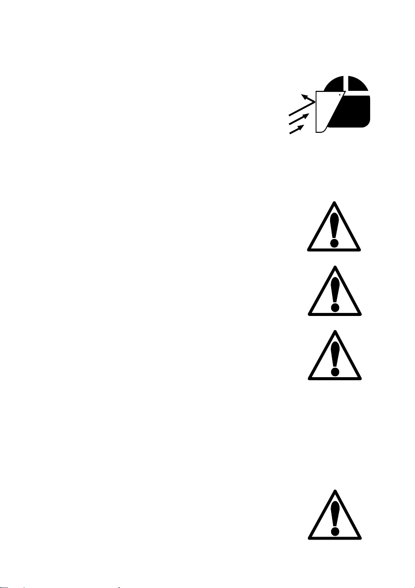
Important Safety Information!
CAUTION:
(Standard version) Never remove the flow sensor
from a pressurized pipe. Always wear safety face
protection during sensor installation/removal.
(Hot-Tap version) Follow the recommended
installation/removal instructions in this manual.
Always wear safety face protection during sensor
installation/removal.
Pipe fittings MUST be installed by a certified
welder only. OMEGA will not assume liability of
any kind for improper fitting installations.
Serious bodily injury and/or damage to the sensor
can result if the conditions and specifications
presented in this manual are exceeded. DO NOT
exceed specifications under any circumstances.
The FP-6000 Hot-Tap system's overall specifications and limitations depend on the lowest maximum rating of the components associated with the
system. In other words, the Hot-Tap system is only
as strong as its weakest link. For example, a ball
valve, a component of the system, is rated at a
maximum 100 psi @ 185 °F, limiting the entire
system's maximum pressure/temperature rating to
100 psi @ 185 °F. All higher maximum specifications MUST yield to the component with the lowest
maximum specification.
Maximum Operating Pressure:
225 psi (15 bar)
Maximum Operating Temperature:
212 °F (100 °C)
Page 6
OMEGA FP-6000, -6001
Adjustable Brass Flow Sensor
Order Number:
FP-6000
1-1/2 in. NPT threads
FP-6001
7/1-R 1-
1/2
ISO threads
Unpacking and Inspection
Your flow sensor package includes the following
items:
OMEGA FP-6000 Series Adjustable Brass Flow Sensor
6 inch ruler (Standard sensor version only)
10 inch brass alignment rod
Warranty Record
For your protection, record your sensor's purchase
information for future reference. The serial number
is located on the metal tag attached to the upper
portion of the sensor body.
Type: OMEGA FP-6000 Series
Adjustable Brass Flow Sensor
OMEGA FP-6002, -6003
Adjustable Brass Flow Sensor
for Hot-Tap installations
Order Number:
FP-6002
1-1/2 in. NPT threads
FP-6003
7/1-R 1-
1/2
ISO threads
Purchase Date: __________________________
Model Number: _________________________
Serial Number: __________________________
Purchased From: _________________________
Purchase Order Number: _________________
Page 7

This manual contains description, specifications
Fluid
Flow
and instruction for the installation, removal, and
operation of the OMEGA FP-6000 Series
Adjustable Brass Flow Sensor. Please read the
manual thoroughly. If you require further
assistance, please contact your OMEGA dealer.
1.1 Description
The FP-6000 Series is an insertion flow sensor
used to measure the flow velocity of fluids through
process pipes. The sensor insertion depth is
adjustable, allowing installation into metal pipes
ranging from 11/2 to 24 inches in diameter (11/
to 36 in. for Hot-Tap). The Hot-Tap version
enables installation in active pipes, reducing
downtime to a minimum. Wetted parts include
C36000 brass, CD4MCu steel, tungsten steel,
Fluoroloy B, and Viton®.
Chapter 1
Introduction
2
The FP-6000 Series mounts on the pipe through
any standard 1
1
/2 inch female pipe fitting. The
unit comes equipped with standard NPT threads
or optional ISO 7/1-R 11/2 threads.
1.2 Theory of Operation
Liquid flowing through a process pipe rotates the
sensor paddlewheel. An AC frequency is induced
into the sensor coil which is proportional to the
fluid velocity in amplitude and frequency. The AC
signal is then input to a control instrument where
the frequency is converted to engineering units and
used to display flow rate and control external
devices.
Patented open-cell rotor
design provides a linear AC
output over a wider velocity
range.
1
Page 8
Chapter 2
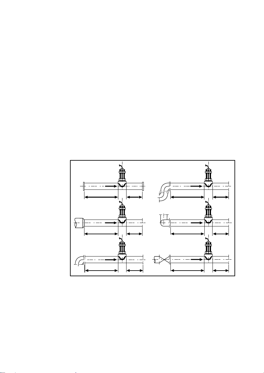
15 X I.D. 5 X I.D.
Reducer
Flange
40 X I.D. 5 X I.D.
2 x 90° Elbow
3 dimensions
20 X I.D. 5 X I.D.
90° Elbow
50 X I.D. 5 X I.D.
Valve/Gate
10 X I.D. 5 X I.D.
25 X D 5 X I.D.
2 x 90°
Elbow
Inlet OutletInlet Outlet
Installation and
Wiring
Figure 1
Sensor upstream/
downstream mounting
requirements
The linearity and accuracy of the FP-6000 Series
sensor depend on predictable flow conditions in
the pipe and proper location of the fitting. As
with any insertion flow sensor, the pipe must be full
and generally free of air pockets.
2.1 Location of Fitting
The sensor must be located in a free-flowing
straight run of pipe. OMEGA recommends a
minimum of 10 pipe diameters of straight pipe
upstream and a minimum of 5 diameters downstream to insure a fully developed flow profile.
Any obstructions to the flow will require considerably longer straight runs. Figure 1 illustrates
several common situations and recommended
piping distances.
2
2.2 Sensor Position
When installing the sensor in a horizontal pipe run
the optimum position is at 0° or 180°, assuming
the line is always full and contains no solids.
Air pockets or sediment in the line will disturb the
rotation of the paddlewheel, causing inaccuracy in
the calibration. Installing the sensor at an angle
Page 9
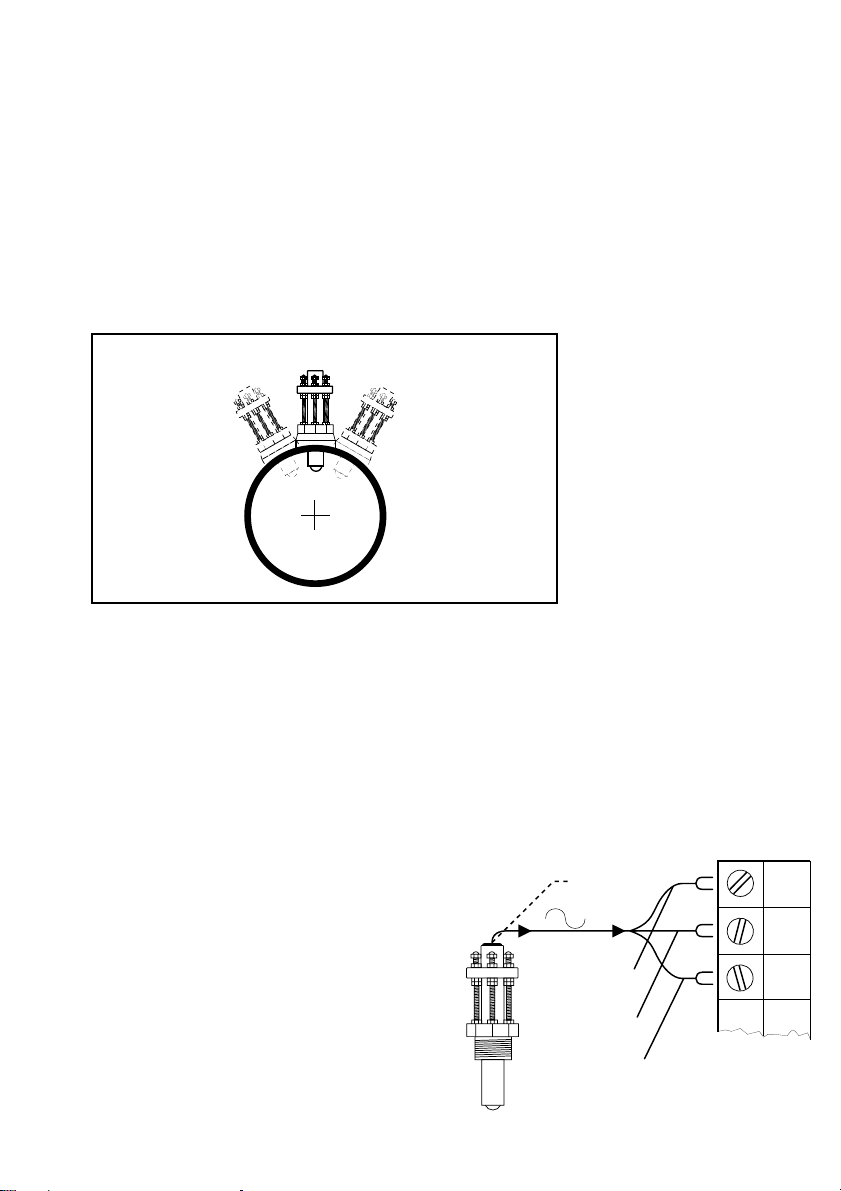
(max. 30°) will help to avoid these problem areas,
blk
F-
red
F+
shld
black
(AC signal out)
red
(AC signal out)
silver
(shield)
instrument
1/2 in. conduit
port
but use caution. Excessive angles will cause
bearing drag at lower flow rates.
On a vertical pipe run locate the sensor where the
flow is upward. If downward flow is necessary
the system must be designed to prevent air/water
vapor pockets from developing in the pipe which
will affect the performance of the sensor.
0°
+30°-30°
Maximum Sensor
Installation Range
Process Pipe
Special Considerations
For Hot-Tap installations allow at least 3 feet of
vertical clearance for sensor installation plus the
distance required for the isolation valve and fittings
attached to the pipe. More clearance may be
necessary to suit the drilling machine used during
sensor installation.
2.3 Sensor Wiring
Both Standard and Hot-Tap sensor
versions include 25 feet of cable. The
cable may be extended up to 200 feet
without amplification. A 1/2 inch
conduit port is available in the sensor to
install the cable in protective conduit.
Figure 2
Sensor Installation Range
Vertical mounting is recommended to provide best
overall performance.
3
Page 10
Chapter 3
Installation
The following items are required to properly install
the OMEGA FP-6000 Series Adjustable Brass flow
sensor.
3.1 Hardware, Standard Sensor
• female pipe fitting (weld-on or saddle)
11/2 in. NPT or ISO 7/1-Rc 1-1/2
•11/4 in. (32 mm) diameter drill
• Pipe thread sealant
• Tape measure
3.2 Hardware, Hot-Tap Sensor
The Hot-Tap sensor requires all the above items
plus:
•Hot-Tap drilling machine (e.g. Mueller drilling
machine or equivalent)
• Female ball or gate valve (full port only)
11/2 in. NPT or ISO 7/1-Rc 1-1/2
Caution: Depressurize and
drain pipe before drilling .
4
• Male pipe nipple, 11/2 x 2 in./32 x 50 mm
11/2 in. NPT or ISO 7/1-R 11/
•Hot-Tap installation tool (purchased separately)
2
3.3 Standard Fitting Installation
1. Depressurize and drain pipe.
2. Wearing safety face protection, drill a 11/4 in.
(32 mm) diameter hole in the pipe.
3. Install the pipe fitting on the outside of the pipe
according to the manufacturer's instructions.
Failure to follow these instructions may result in
bodily injury and/or product failure.
Page 11

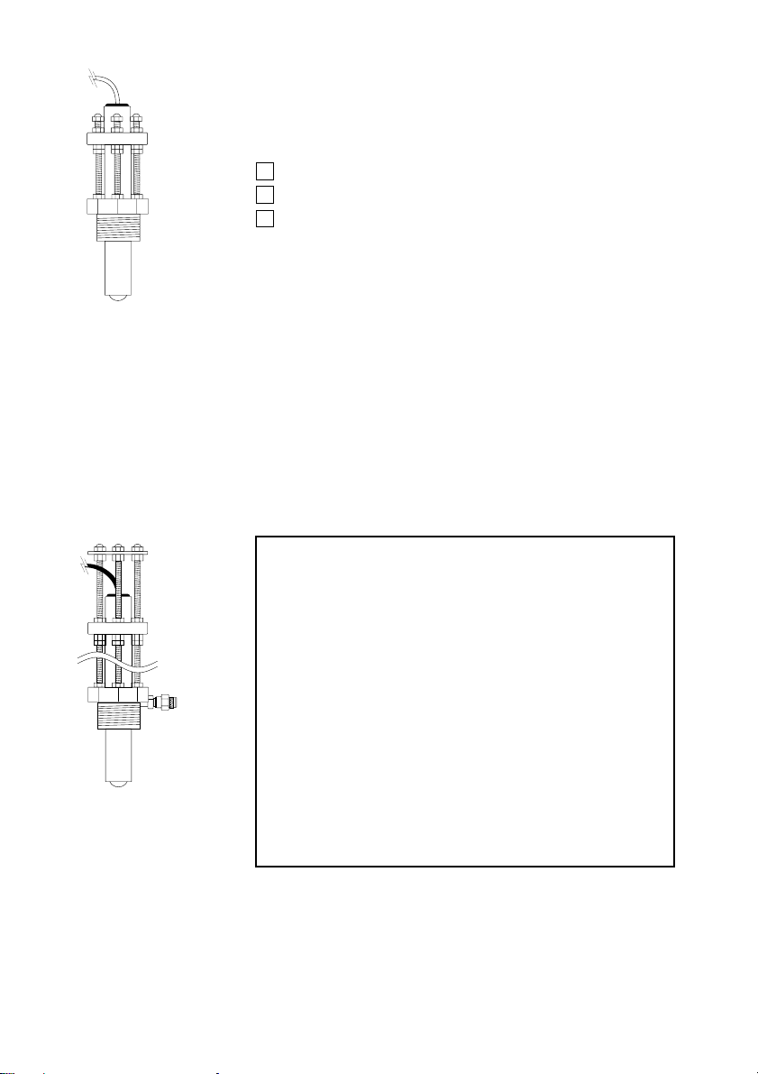
4. Remove brass sensor nut from sensor.
brass sensor nut
pipe fitting
(Teflon tape recommended)
process pipe
5. Thread brass sensor nut into pipe fitting.
3.4 Hot-Tap Fitting Installation
1. Install the pipe fitting on the outside diameter of
the pipe according to the manufacturer's instructions. Failure to follow these instructions may result
in bodily injury and/or product failure.
2. Install the pipe nipple and isolation valve (ball
or gate valve) onto the external pipe fitting using
pipe sealant on the threads.
customer supplied
ball or gate valve
customer supplied
nipple; 1.25 x 2 in.
(32 x 50 mm) long
process pipe
(side view)
3. Wearing safety face protection, install an
appropriate hole cutting tool per manufacturers
instructions (e.g. Mueller drilling machine) with a
1
/4 in. (32 mm) drill onto the top of the isolation
1
valve, ensuring a tight fit. Use the recommended
drill bit size or damage to the isolation valve
may occur.
5
Page 12

A
B
1
2
3
4
5
6
1
2
3
4
5
A
B
1
2
3
4
5
6
1
2
3
4
5
I.D.
wall
thickness
A
B
1
2
3
4
5
6
1
2
3
4
5
incorrect
correct
brass sensor nut
bleed valve
make sure
bleed valve
clears isolation
valve handle
process pipe
For Hot-Tap installations, we
assume pipe dimensions are
known
Wall
thickness:____________
4. Open the isolation valve and insert the drill
through the valve and cut the sensor clearance
hole. After the hole is cut, withdraw the drill from
the isolation valve and close the valve. Remove
the drilling machine per manufacturer's instructions.
5. Install brass sensor nut/bleed valve into the top
of the isolation valve. Make sure the bleed valve
clears the handle of the isolation valve during
operation.
3.5 Calculating the H Dimension
Before installing the sensor some critical dimensions must be established. The rotor shaft must be
located 10% inside the pipe I.D. to insure accurate
calibration capability. To accomplish this, the "H"
dimension is measured from the outside surface of
the pipe to the bottom of the sensor flange.
Nominal "H" dimensions for standard pipes are
listed on page 18-19. For irregular pipe dimensions, calculate the "H" dimension using the given
formulas (page 7). The 6 inch ruler may be used
to measure the I.D. and wall thickness of pipes up
to 5 inch (standard sensors only).
I.D.: ________________
For standard sensor installations, the ruler may be used to
measure wall thickness and
I.D. of pipes up to 5 inches in
diameter.
6
Page 13

Standard Sensor
"H"
alignment rod
sensor flange
process pipe
direction of flow
pipe side view
process pipe (side view)
direction of flow
alignment rod
"H"
protector plate
H = 5.95 - pipe wall thickness - (0.10 X I.D.)
Example:
3.0 inch schedule 80 wrought steel;
Wall thickness= 0.3 in.
Inside diameter = 2.9 in.
H = 5.95 - 0.3 - (0.10 X 2.9)
H = 5.36 in.
Hot-Tap Sensor
H = 15.00 - pipe wall thickness - (0.10 X I.D.)
Record your pipes "H"
dimension for future
reference:
H= _________________
Example:
10 inch schedule 40 wrought steel;
Wall thickness= 0.365 in.
Inside diameter = 10.02 in.
H = 15.00 - 0.365 - (0.10 X 10.02)
H = 13.633 in.
Record your pipes "H"
dimension for future
reference:
H= _________________
7
Page 14

Step 1
brass sensor nut
Step 2
hex nut
lock washer
Once the correct dimensions are calculated and
recorded, the sensor can be installed in the fitting.
The Standard and Hot-Tap versions require
substantially different procedures.
3.6 Standard Installation
1. Thread one hex nut onto each of the three
threaded rods included in package. Install
threaded rod with a lock-washer onto the brass
sensor nut. Secure rods in place by tightening
each hex nut against the brass sensor nut.
2. Thread one jam nut and lower hex nut onto
each stud so that the top surface of each nut is at
the proper "H" dimension for your pipe. Secure
each hex nut with a jam nut.
3. Insert the flow sensor into the brass sensor nut,
making sure the alignment hole on the sensor
flange is pointing downstream.
lower hex nut, 2nd
jam nut, 1'st
lower hex nuts
(3/16 x 1/4-20)
jam nuts
(5/32 x 1/4-20)
"H"
hex nut and lock washer
brass sensor nut
process pipe
8
Page 15

4. Place the alignment rod in the hole on the
sensor flange. Align the flange so rod is parallel
to the process pipe.
sensor flange
alignment rod
direction of flow
process pipe (top view)
The flow sensor alignment rod MUST be
parallel to the process pipe as shown.
5. Thread upper hex nuts with lock-washers until
they contact the sensor flange and tighten. Check
for proper "H" dimension and readjust if necessary.
cap nuts
upper hex nuts
and lock-washers
lower
hex nuts
5.95 in.
(151 mm)
sensor flange
jam nuts
brass sensor nut
FLOW
"H"
1-1/2 in. NPT or
ISO 7/1-Rc 1-
female pipe fitting
process pipe
1/2
in.
FLOW
10% of I.D.
wall
thickness
pipe I.D.
9
Page 16

Step 1
lower hex nuts
(3/16 x 1/4-20)
jam nuts
(5/32 x 1/4-20)
13.75 in.
(350 mm)
brass sensor nut
brass sensor nut
Step 2
hex nut
lock washer
3.7 Hot-Tap Installation
1. Thread one hex nut onto each of the three
threaded rods included in package. Install
threaded rod with a lock-washer onto the brass
sensor nut. Secure rods in place by tightening
each hex nut against the brass sensor nut.
2. Thread one jam nut and lower hex nut onto
each stud so the top surface of each nut is 13.75
in. (350 mm) from top surface of brass sensor nut.
Secure each hex nut with a jam nut.
This setting is critical to ensure an adequate
sensor seal and to prevent the rotor from hitting
the isolation valve orifice during installation.
lower hex nut, 2nd
jam nut, 1'st
10
Page 17

3. Wipe the FP-6000 Series sensor body with a
dry, clean cloth. Orient the alignment hole on the
sensor flange to point downstream. Place the
slotted flange over the threaded rods. Lower the
sensor into fitting until the sensor flange rests on
the lower hex and jam nuts.
4. Secure the sensor with lock-washers and upper
hex nuts on the top of the flange. Before tightening, align the sensor flange so that the alignment
rod is parallel and level with the process pipe.
5. Make sure the bleed valve is closed (full
clockwise position).
sensor flange
direction of flow
The flow sensor alignment rod MUST be
parallel to the process pipe as shown.
alignment rod
process pipe (top view)
sensor flange
lower hex nut and
jam nuts
18 inch threaded rods
Brass sensor nut
Upper hex nuts
(3/16 x 1/4-20)
1/4 in. lock washers
alignment rod
13.75 in.
Bleed valve
direction of flow
process pipe (side view)
11
Page 18

swivel mount
w/cable port
installation tool
threaded shaft
sensor flange
sensor
cable
bearing plate
cap nuts
protector plate
hex nuts
sensor body
protector plate
cap nuts
1.0 in.
(25 mm)
Using the Hot-Tap Installation Tool
The Hot-Tap installation tool helps to lower the
sensor into place against the pressure in the pipe.
1. Thread protector plate hex nuts onto each of the
three threaded rods. Adjust each hex to a height
of approximately 1 in. (25 mm) from the top of
each rod. Remove the black plastic cable grommet in top of sensor with a screwdriver. Slide the
grommet up the cable away from sensor.
2. Position the installation tool bearing plate by
rotating it so that it is approximately 2 inches away
from the swivel mount. Mount the installation tool
by placing the threaded rods through the holes in
the tool's bearing plate, resting the bearing plate
on top of the protector plate hex nuts. Make sure
the swivel mount's ears are mounted between the
threaded rods (not over the rods). Install the
bearing plate cap nuts. Tighten the bearing plate
cap nuts to secure the installation tool in place.
Protector plate
removed during
sensor installation
Protector plate hex nut
(3/16 x 1/4-20)
cable
grommit
12
Page 19

3. Align the sensor cable with the swivel mount
cable port to prevent cable pinching. Use a
3/8 inch wrench or socket to turn the installation
tool shaft clockwise until it is seated in the hole at
the top of the sensor flange.
4. Wearing safety face protection, slowly open
the isolation valve to the full open position.
Loosen the lower hex and jam nuts and move them
to the required "H" dimension. Turn the installation
tool shaft clockwise until the sensor flange contacts
the lower hex and jam nuts. Thread the upper hex
nuts down until they contact the sensor flange.
Tighten the upper hex nuts to secure the sensor.
5. Remove cap nuts and withdraw the installation
tool by turning shaft counterclockwise. Be careful
to not damage cable. Snap cable grommet into
top of sensor and replace protector plate and cap
nuts.
installation tool
shaft
upper hex nuts
cap nuts
alignment rod
lower hex nuts
jam nuts
protector plate
cap nuts
protector plate
protector plate
hex nut
"H"
direction of flow
13
Page 20

Chapter 4
Sensor Removal
Procedures
4.1 Standard Sensor Removal
To remove the Standard FP-6000 Series sensor
from a depressurized empty pipe, simply remove
the cap nuts and upper hex nuts located above the
sensor flange. Pull up on sensor flange with
twisting motion.
4.2 Hot-Tap Sensor Removal
To remove the Hot-Tap sensor safely from a
pressurized active pipe, the entire installation
process must be reversed.
14.2 in.
(361 mm)
protector plate
cap nuts
protector plate
protector plate
hex nut
1. Remove the cap nuts, protector plate, protector
plate hex nuts, and sensor cable grommet.
2. Thread installation tool in place and secure
bearing plate in place of sensor protector plate.
3. Turn shaft of installation tool clockwise to lower
tool into opening in sensor flange. Guide cable
into the port to prevent damage.
installation tool
threaded shaft
4. Wearing
upper hex nuts
and lock washers
sensor flange
lower hex and
jam nuts
safety face
protection,
loosen the upper
hex nuts and raise to 14.2 in.
(361 mm) from top of brass
sensor nut to bottom of nut. This
measurement is critical to
maintain watertight seal in
sensor while allowing clearance
to close the isolation valve.
14
process pipe (side view)
Page 21

installation tool
threaded shaft
cap nuts
protector plate
hex nuts
sensor cable
upper hex nuts
installation tool
bearing plate
swivel mount
w/cable port
sensor flange
1 lower hex nut
and jam nut
sensor body
5. Wearing safety face protection, turn the
installation tool shaft counterclockwise to withdraw
sensor until the sensor flange contacts the upper
hex nuts.
6. Raise one lower hex and jam nut to bottom of
sensor flange.
7. Close valve, remove bearing plate and tool.
To remove the sensor
8. Wearing safety face protection, cover the
bleed valve with suitable protection (rag, towel,
etc.) and open the bleed valve (ccw rotation) to
relieve internal pressure. Pull sensor up until bleed
valve purges some fluid (indicating sensor is past
1st o-ring seal inside brass sensor nut) then remove
sensor from brass sensor nut/threaded rod
assembly.
Caution: In case of a leaky isolation valve, the
sensor will be under a slight amount of pressure.
Care should be taken when removing the sensor.
Use the bleed valve to relieve this pressure taking
care not to spray fluid on yourself or others.
When reinstalling the
sensor:
hex nut in position to guide
sensor to proper height before
opening valve. Return to "H"
dimension height after valve is
opened.
leave one lower
15
Page 22

Chapter 5
Maintenance
5.1 Maintenance
All versions of the FP-6000 series sensor require
little or no maintenance, with the exception of an
occasional sensor/paddlewheel cleaning.
and
Replacement
Parts
♦Rotor Kit
retainer retainer
rotor shaft
bearing
rotor
Refer to rotor replacement
instructions, pg# 17
bearing
5.2 Replacement Parts
(Standard version)
1. Standard sensor assembly FP-6000, -6001
2. Rotor kit (bearings, shaft, retainers, and rotor
included), see table below♦
• FP52509-1 kit with stainless steel shaft
• FP52509-2 kit with Tungsten Carbide shaft
3. Instruction manual M-2973
FP52509-1 Rotor Kit
• Retainer material: 316 stainless steel
• Rotor shaft material: 316 stainless steel
• Bearing material: Fluoroloy B
• Rotor material: CD4MCu stainless steel
FP52509-2 Rotor Kit
• Retainer material: 316 stainless steel
• Rotor shaft material: Tungsten Carbide
• Bearing material: Fluoroloy B
• Rotor material: CD4MCu stainless steel
16
(Hot-Tap version)
4. Hot-Tap sensor assembly FP-6000, -6001
5. Rotor kit (bearings, shaft, retainers, and rotor
included), see table above♦
• FP52509-1 kit with stainless steel shaft
• FP52509-2 kit with Tungsten Carbide shaft
6. Instruction manual M-2973
Page 23

5.3 Rotor Replacement Procedure
Rotor Pin
Rotor Pin
Existing
Retainer
New
Bearings
Rotor
Assembly
1. With a small pair of needle-nose pliers, firmly
grip the center of the rotor pin (axle) and with a
twisting motion, bend the rotor pin into an "S"
shape. This should pull the ends of the pin out of
the shaft retainers and free the rotor assembly.
2. Remove shaft retainer from each side by gently
tapping it inwards using a punch. Install a new
shaft retainer with the rotor shaft clearance hole
inward. Only install one shaft retainer at this
time.
3. Insert the new rotor assembly and bearings into
the rotor housing of the sensor and place the new
rotor pin (axle) through the open end of the rotor
housing, through the rotor and bearings, and into
the previously installed shaft retainer.
4. Tap the second shaft retainer (rotor shaft clearance hole inwards) into the hole while lining up the
rotor pin with the center of the shaft retaining hole.
This completes the rotor replacement procedure.
Retainer
Punch
17
Page 24

H Dimensions
H Dimensions for Standard Sensors
Wrought Steel Pipe Per ANSI 36.10
NPS SCH 40 SCH 80 STD XS
1-1/2 in.
2 in.
2-1/2 in.
3 in.
3-1/2 in.
4 in.
5 in.
6 in.
8 in.
10 in.
12 in.
14 in.
16 in.
18 in.
20 in.
22 in.
24 in..
5.644 in.
5.589 in.
5.500 in.
5.427 in.
5.369 in.
5.310 in.
5.187 in.
5.064 in.
4.830 in.
4.583 in.
4.350 in.
4.200 in.
3.950 in.
3.700 in.
3.475 in.
*
3.000 in.
5.600 in.
5.538 in.
5.442 in.
5.360 in.
5.296 in.
5.230 in.
5.094 in.
4.942 in.
4.688 in.
4.400 in.
4.125 in.
3.950 in.
3.675 in.
3.400 in.
3.125 in.
2.850 in.
2.575 in.
5.644 in.
5.589 in.
5.500 in.
5.427 in.
5.369 in.
5.310 in.
5.187 in.
5.064 in.
4.830 in.
4.583 in.
4.375 in.
4.250 in.
4.050 in.
3.850 in.
3.650 in.
3.450 in.
3.250 in.
Conversion:
Stainless Steel Pipe Per ANSI B36.19
mm = inches (25.4)
5.600 in.
5.538 in.
5.442 in.
5.360 in.
5.296 in.
5.230 in.
5.094 in.
4.942 in.
4.688 in.
4.475 in.
4.275 in.
4.150 in.
3.950 in.
3.750 in.
3.550 in.
3.350 in.
3.150 in.
NPS SCH 5S SCH 10S SCH 40S SCH 80S
1-1/2 in.
2 in.
2-1/2 in.
3 in.
3-1/2 in.
4 in.
5 in.
6 in.
8 in.
10 in.
12 in.
14 in.
16 in.
18 in.
20 in.
22 in.
24 in.
(*) represents values currently unavailable
5.708 in.
5.660 in.
5.596 in.
5.534 in.
5.484 in.
5.434 in.
5.306 in.
5.200 in.
5.000 in.
4.768 in.
4.550 in.
4.425 in.
4.218 in.
4.018 in.
3.800 in.
3.600 in.
3.376 in.
5.673 in.
5.625 in.
5.567 in.
5.504 in.
5.454 in.
5.404 in.
5.287 in.
5.180 in.
4.969 in.
4.743 in.
4.531 in.
4.400 in.
4.200 in.
4.000 in.
3.776 in.
3.576 in.
3.350 in.
5.644 in.
5.589 in.
5.500 in.
5.427 in.
5.369 in.
5.310 in.
5.187 in.
5.064 in.
4.830 in.
4.583 in.
4.375 in.
*
*
*
*
*
*
18
5.600 in.
5.538 in.
5.442 in.
5.360 in.
5.296 in.
5.230 in.
5.094 in.
4.942 in.
4.688 in.
4.475 in.
4.275 in.
*
*
*
*
*
*
Page 25

H Dimensions for Hot-Tap Sensors
H Dimensions
Wrought Steel Pipe Per ANSI 36.10
NPS SCH 40 SCH 80 STD XS
1-1/2 in.
2 in.
2-1/2 in.
3 in.
3-1/2 in.
4 in.
5 in.
6 in.
8 in.
10 in.
12 in.
14 in.
16 in.
18 in.
20 in.
22 in.
24 in.
14.694 in.
14.639 in.
14.550 in.
14.477 in.
14.419 in.
14.360 in.
14.237 in.
14.144 in.
13.880 in.
13.633 in.
13.400 in.
13.250 in.
13.000 in.
12.750 in.
12.525 in.
*
12.050 in.
14.650 in.
14.588 in.
14.492 in.
14.410 in.
14.346 in.
14.280 in.
14.144 in.
13.992 in.
13.738 in.
13.450 in.
13.175 in.
13.000 in.
12.725 in.
12.450 in.
12.175 in.
11.900 in.
11.625 in.
14.694 in.
14.639 in.
14.550 in.
14.477 in.
14.419 in.
14.360 in.
14.237 in.
14.144 in.
13.880 in.
13.633 in.
13.425 in.
13.300 in.
13.100 in.
12.900 in.
12.700 in.
12.500 in.
12.300 in.
Conversion:
Stainless Steel Pipe Per ANSI B36.19
mm = inches (25.4)
14.650 in.
14.588 in.
14.492 in.
14.410 in.
14.346 in.
14.280 in.
14.144 in.
13.992 in.
13.738 in.
13.525 in.
13.325 in.
13.200 in.
13.000 in.
12.800 in.
12.600 in.
12.400 in.
12.200 in.
NPS SCH 5S SCH 10S SCH 40S SCH 80S
1-1/2 in.
2 in.
2-1/2 in.
3 in.
3-1/2 in.
4 in.
5 in.
6 in.
8 in.
10 in.
12 in.
14 in.
16 in.
18 in.
20 in.
22 in.
24 in.
(*) represents values currently unavailable
14.758 in.
14.711 in.
14.646 in.
14.584 in.
14.534 in.
14.484 in.
14.357 in.
14.250 in.
14.050 in.
13.818 in.
13.600 in.
13.475 in.
13.268 in.
13.068 in.
12.850 in.
12.650 in.
12.426 in.
14.723 in.
14.675 in.
14.617 in.
14.554 in.
14.504 in.
14.454 in.
14.337 in.
14.230 in.
14.019 in.
13.793 in.
13.581 in.
13.450 in.
13.250 in.
13.050 in.
12.826 in.
12.626 in.
12.400 in.
14.694 in.
14.639 in.
14.550 in.
14.477 in.
14.419 in.
14.360 in.
14.237 in.
14.144 in.
13.880 in.
13.633 in.
13.425 in.
*
*
*
*
*
*
14.650 in.
14.588 in.
14.492 in.
14.410 in.
14.346 in.
14.280 in.
14.144 in.
13.992 in.
13.738 in.
13.525 in.
13.325 in.
*
*
*
*
*
*
19
Page 26

K-factors
Stainless Steel
SCH 5S STAINLESS STEEL PIPE PER ANSI B36.19
K-FACTOR K-FACTOR A-FACTOR A-FACTOR
PIPE PULSES/ PULSES/ U.S.
SIZE U.S. GAL LITER GPM/HZ LPM/HZ
104.200 27.5297 0.5758 2.1795
1 1/2
2 67.160 17.7437 0.8934 3.3815
2 1/2 46.060 12.1691 1.3026 4.9305
3 29.790 7.8705 2.0141 7.6234
3 1/2 22.060 5.8283 2.7199 10.295
4 16.890 4.4624 3.5524 13.446
5 10.6500 2.8137 5.6338 21.324
67.1160 1.8801 8.4317 31.914
83.8700 1.0225 15.504 58.682
10 2.3570 0.6227 25.456 096.35
12 1.6060 0.4243 37.360 141.41
14 1.2980 0.3429 46.225 174.96
16 0.9620 0.2542 62.370 236.07
18 0.7400 0.1955 81.081 306.89
20 0.5900 0.1559 101.695 384.92
22 0.4790 0.1266 125.26 474.11
24 0.3990 0.1054 150.38 569.17
SCH 10S STAINLESS STEEL PIPE PER ANSI B36.19
K-FACTOR K-FACTOR A-FACTOR A-FACTOR
PIPE PULSES/ PULSES/ U.S.
SIZE U.S. GAL LITER GPM/HZ LPM/HZ
113.600 30.0132 0.5282 1.9991
1 1/2
2 72.560 19.1704 0.8269 3.1298
2 1/2 48.750 12.8798 1.2308 4.6585
3 31.250 8.2563 1.9200 7.2672
3 1/2 23.010 6.0793 2.6076 09.870
4 17.540 4.6341 3.4208 12.948
5 10.8700 2.8719 5.5198 20.892
67.2410 1.9131 8.2861 31.363
83.9520 1.0441 15.182 57.465
10 2.3880 0.6309 25.126 095.10
12 1.6200 0.4280 37.037 140.19
14 1.3110 0.3464 45.767 173.23
16 0.9680 0.2557 61.983 234.61
18 0.7440 0.1966 80.645 305.24
20 0.5930 0.1567 101.180 382.97
22 0.4820 0.1273 124.48 471.16
24 0.4020 0.1062 149.25 564.93
SCH 40S STAINLESS STEEL PIPE PER ANSI B36.19
K-FACTOR K-FACTOR A-FACTOR A-FACTOR
PIPE PULSES/ PULSES/ U.S.
SIZE U.S. GAL LITER GPM/HZ LPM/HZ
122.000 32.2325 0.4918 1.8615
1 1/2
2 78.690 20.7900 0.7625 2.8860
2 1/2 55.630 14.6975 1.0786 4.0823
3 35.530 9.3871 1.6887 6.3918
3 1/2 26.070 6.8877 2.3015 08.711
4 19.840 5.2417 3.0242 11.447
5 12.090 3.1942 4.9628 18.784
68.0410 2.1244 7.4618 28.243
84.3500 1.1493 13.793 52.207
10 2.6080 0.6890 23.006 87.078
12 1.7400 0.4597 34.483 130.52
14 ****
16 ****
18 ****
20 ****
22 ****
24 ****
SCH 80S STAINLESS STEEL PIPE PER ANSI B36.19
K-FACTOR K-FACTOR A-FACTOR A-FACTOR
PIPE PULSES/ PULSES/ U.S.
SIZE U.S. GAL LITER GPM/HZ LPM/HZ
136.100 35.9577 0.4409 1.6686
1 1/2
2 88.590 23.4055 0.6773 2.5635
2 1/2 62.810 16.5945 0.9553 3.6157
3 39.990 10.5654 1.5004 5.6789
3 1/2 29.220 7.7199 2.0534 7.7721
4 22.160 5.8547 2.7076 10.248
5 13.420 3.5456 4.4709 16.923
69.0160 2.3820 6.6548 25.189
84.8190 1.2732 12.451 47.126
10 2.7730 0.7326 21.637 81.897
12 1.8240 0.4819 32.895 124.51
14 ****
16 ****
18 ****
20 ****
22 ****
24 ****
Page 27

STD WROUGHT STEEL PIPE PER ANSI B36.10
SCH 40 WROUGHT STEEL PIPE PER ANSI B36.10
K-FACTOR K-FACTOR A-FACTOR A-FACTOR
PIPE PULSES/ PULSES/ U.S.
SIZE U.S. GAL LITER GPM/HZ LPM/HZ
1 1/2 122.000
32.232 0.4918 1.8615
2 78.690 20.790 0.7625 2.8860
2 1/2 55.630 14.697 1.0786 4.0823
3 35.530 9.3871 1.6887 6.3918
3 1/2 26.070 6.8877 2.3015 08.711
4 19.840 5.2417 3.0242 11.447
5 12.090 3.1942 4.9628 18.784
6 8.0410 2.1244 7.4618 28.243
8 4.3500 1.1493 13.793 52.207
10 2.6080 0.6890 23.006 87.078
12 1.7610 0.4653 34.072 128.96
14 1.4250 0.3765 42.105 159.37
16 1.0590 0.2798 56.657 214.45
18 0.8180 0.2161 73.350 277.63
20 0.6460 0.1707 92.879 351.55
22 ****
24 0.4350 0.1149 137.93 522.07
SCH 80 WROUGHT STEEL PIPE PER ANSI B36.10
K-FACTOR K-FACTOR A-FACTOR A-FACTOR
PIPE PULSES/ PULSES/ U.S.
SIZE U.S. GAL LITER GPM/HZ LPM/HZ
1 1/2
136.100 35.9577 0.4409 1.6686
2 88.590 23.4055 0.6773 2.5635
2 1/2 62.810 16.5945 0.9553 3.6157
3 39.990 10.5654 1.5004 5.6789
3 1/2 29.220 7.7199 2.0534 7.7721
4 22.160 5.8547 2.7076 10.248
5 13.420 3.5456 4.4709 16.923
6 9.0160 2.3820 6.6548 25.189
8 4.8190 1.2732 12.451 47.126
10 2.8970 0.7654 20.711 78.391
12 1.9620 0.5184 30.581 115.75
14 1.5890 0.4198 37.760 142.92
16 1.1750 0.3104 51.064 193.28
18 0.9040 0.2388 66.372 251.22
20 0.7160 0.1892 83.799 317.18
22 0.5820 0.1538 103.093 390.21
24 0.4820 0.1273 124.48 471.16
K-FACTOR K-FACTOR A-FACTOR A-FACTOR
PIPE PULSES/ PULSES/ U.S.
SIZE U.S. GAL LITER GPM/HZ LPM/HZ
122.000 32.2325 0.4918 1.8615
1 1/2
2 78.690 20.7900 0.7625 2.8860
2 1/2 55.630 14.6975 1.0786 4.0823
3 35.530 9.3871 1.6887 6.3918
3 1/2 26.070 6.8877 2.3015 08.711
4 19.840 5.2417 3.0242 11.447
5 12.090 3.1942 4.9628 18.784
6 8.0410 2.1244 7.4618 28.243
8 4.3500 1.1493 13.793 52.207
10 2.6080 0.6890 23.006 87.078
12 1.7400 0.4597 34.483 130.52
14 1.3950 0.3686 43.011 162.80
16 1.0220 0.2700 58.708 222.21
18 0.7800 0.2061 76.923 291.15
20 0.6150 0.1625 97.561 369.27
22 0.4970 0.1313 120.72 456.94
24 0.4110 0.1086 145.99 552.55
XS WROUGHT STEEL PIPE PER ANSI B36.10
K-FACTOR K-FACTOR A-FACTOR A-FACTOR
PIPE PULSES/ PULSES/ U.S.
SIZE U.S. GAL LITER GPM/HZ LPM/HZ
136.100 35.9577 0.4409 1.6686
1 1/2
2 88.590 23.4055 0.6773 2.5635
2 1/2 62.810 16.5945 0.9553 3.6157
3 39.990 10.5654 1.5004 5.6789
3 1/2 29.220 7.7199 2.0534 7.7721
4 22.160 5.8547 2.7076 10.248
5 13.420 3.5456 4.4709 16.923
6 9.0160 2.3820 6.6548 25.189
8 4.8190 1.2732 12.451 47.126
10 2.7730 0.7326 21.637 81.897
12 1.8240 0.4819 32.895 124.51
14 1.4550 0.3844 41.237 156.08
16 1.0590 0.2798 56.657 214.45
18 0.8050 0.2127 74.534 282.11
20 0.6320 0.1670 94.937 359.34
22 0.5100 0.1347 117.65 445.29
24 0.4200 0.1110 142.86 540.71
K-factors
Wrought Steel
21
Page 28

K-factors
Plastic Pipe
Schedule 40 Plastic pipe per ASTM-D-1785
K-FACTOR K-FACTOR A-FACTOR A-FACTOR
PIPE PULSES/ PULSES/ U.S.
SIZE U.S. GAL LITER GPM/HZ LPM/HZ
124.400 32.8666 0.4823 1.8256
1 1/2
2 80.140 21.1731 0.7487 2.8338
2 1/2 56.730 14.9881 1.0576 4.0032
3 36.180 9.5588 1.6584 6.2769
3 1/2 26.500 7.0013 2.2642 8.5698
4 20.140 5.3210 2.9791 11.276
5 12.250 3.2365 4.8980 18.539
6 8.1430 2.1514 7.3683 27.889
8 4.3980 1.1620 13.643 51.637
10 2.6340 0.6959 22.779 86.219
12 1.7770 0.4695 33.765 127.80
Schedule 80 Plastic pipe per ASTM-D-1785
K-FACTOR K-FACTOR A-FACTOR A-FACTOR
PIPE PULSES/ PULSES/ U.S.
SIZE U.S. GAL LITER GPM/HZ LPM/HZ
139.400 36.8296 0.4304 1.6291
1 1/2
2 90.790 23.9868 0.6609 2.5014
2 1/2 64.610 17.0700 0.9286 3.5149
3 41.050 10.8454 1.4616 5.5323
3 1/2 29.940 7.9102 2.0040 7.5852
4 22.660 5.9868 2.6478 10.022
5 13.700 3.6196 4.3796 16.577
69.1990 2.4304 6.5224 24.687
84.9060 1.2962 12.230 46.290
10 2.9450 0.7781 20.374 77.114
12 1.9930 0.5266 30.105 113.95
K-factors and A-factors are listed in
U.S. gallons and in liters. Conversion
formulas for other engineering units
are listed below.
K = 60/A
by the FP-6000 series paddlewheel per unit of
liquid in a specific pipe size.
• The A-factor is the flow rate (per minute) repre-
• The K-factor is the number of pulses generated
A = 60/K
sented by 1 Hz output from the FP-6000 series
sensor in a specific pipe size.
To convert K from to multiply K by
U.S. gallons cubic feet 7.479
U.S. gallons cubic inches 0.00433
U.S. gallons cubic meters 263.85
U.S. gallons pounds of water 0.120
U.S. gallons acre feet 325853
U.S. gallons liters 0.264
U.S. gallons Imperial gallons 1.201
To convert K from to multiply K by
liters cubic meters 1000
liters kilograms of water 1
liters gallons 3.785
22
Page 29

General Data
Flow velocity range: 1.6 to 20 ft/s
0.5 to 6 m/s
Linearity: ±1% of full range
Repeatability: ±0.5% of full range
Pipe sizes:
Standard version: 1.5 to 24 in.
(38 to 610 mm)
Hot-Tap version: 1.5 to 36 in.
(38 to 914 mm)
Cable length: 25 ft (7.6 m), can extend
up to 200 ft (61 m)
without amplification
Materials
Sensor material: C36000 free cutting
brass
Specifications
Rotor material: CD4MCu stainless steel
Rotor bearings: Fluoroloy B®
Rotor shaft: 316 stainless steel (opt.)
Tungsten Carbide (std.)
O-ring material: Viton®
Electrical Data
Power requirements: Self powered
Load impedance: 0 to 1000 Ω max.
Ambient Conditions
Maximum
23
Page 30

Specifications
operating pressure: 225 psi (15 bar)
Maximum
operating temperature: 212°F (100 °C)
Caution: The FP-6002 and FP-6003 Series HotTap system's overall specifications and limitations
depend on the lowest maximum rating of the
components associated with the system. For
example, a ball valve, a component of the system,
is rated at a maximum 100 psi @ 185°F, limiting
the entire system's maximum pressure/temperature
rating to 100 psi @ 185°F. All higher maximum
specifications MUST yield to the component with
the lowest maximum specification.
Note: Pressure/temperature specifications refer to
sensor performance in water. Certain chemical
limitations may apply. Chemical compatibility
should be verified before sensor installation.
24
Page 31

WARRANTY/DISCLAIMER
OMEGA ENGINEERING, INC. warrants this unit to be free of defects in materials and workmanship for a
period of 13 months from date of purchase. OMEGA’s WARRANTY adds an additional one (1) month
grace period to the normal one (1) year product warranty to cover handling and shipping time. This
ensures that OMEGA’s customers receive maximum coverage on each product.
If the unit malfunctions, it must be returned to the factory for evaluation. OMEGA’s Customer Service
Department will issue an Authorized Return (AR) number immediately upon phone or written request.
Upon examination by OMEGA, if the unit is found to be defective, it will be repaired or replaced at no
charge. OMEGA’s WARRANTY does not apply to defects resulting from any action of the purchaser,
including but not limited to mishandling, improper interfacing, operation outside of design limits,
improper repair, or unauthorized modification. This WARRANTY is VOID if the unit shows evidence of
having been tampered with or shows evidence of having been damaged as a result of excessive corrosion;
or current, heat, moisture or vibration; improper specification; misapplication; misuse or other operating
conditions outside of OMEGA’s control. Components which wear are not warranted, including but not
limited to contact points, fuses, and triacs.
OMEGA is pleased to offer suggestions on the use of its various products. However,
OMEGA neither assumes responsibility for any omissions or errors nor assumes liability for any
damages that result from the use of its products in accordance with information provided
by OMEGA, either verbal or written. OMEGA warrants only that the parts manufactured by it
will be as specified and free of defects. OMEGA MAKES NO OTHER WARRANTIES OR
REPRESENTATIONS OF ANY KIND WHATSOEVER, EXPRESS OR IMPLIED, EXCEPT THAT OF
TITLE, AND ALL IMPLIED WARRANTIES INCLUDING ANY WARRANTY OF MERCHANTABILITY
AND FITNESS FOR A PARTICULAR PURPOSE ARE HEREBY DISCLAIMED. LIMITATION OF
LIABILITY: The remedies of purchaser set forth herein are exclusive, and the total liability of
OMEGA with respect to this order, whether based on contract, warranty, negligence,
indemnification, strict liability or otherwise, shall not exceed the purchase price of the
component upon which liability is based. In no event shall OMEGA be liable for
consequential, incidental or special damages.
CONDITIONS: Equipment sold by OMEGA is not intended to be used, nor shall it be used: (1) as a “Basic
Component” under 10 CFR 21 (NRC), used in or with any nuclear installation or activity; or (2) in medical
applications or used on humans. Should any Product(s) be used in or with any nuclear installation or
activity, medical application, used on humans, or misused in any way, OMEGA assumes no responsibility
as set forth in our basic WARRANTY / DISCLAIMER language, and, additionally, purchaser will indemnify
OMEGA and hold OMEGA harmless from any liability or damage whatsoever arising out of the use of the
Product(s) in such a manner.
RETURN REQUESTS/INQUIRIES
Direct all warranty and repair requests/inquiries to the OMEGA Customer Service Department. BEFORE
RETURNING ANY PRODUCT(S) TO OMEGA, PURCHASER MUST OBTAIN AN AUTHORIZED RETURN
(AR) NUMBER FROM OMEGA’S CUSTOMER SERVICE DEPARTMENT (IN ORDER TO AVOID
PROCESSING DELAYS). The assigned AR number should then be marked on the outside of the return
package and on any correspondence.
The purchaser is responsible for shipping charges, freight, insurance and proper packaging to prevent
breakage in transit.
FOR
WARRANTY RETURNS, please have the
following information available BEFORE
contacting OMEGA:
1. Purchase Order number under which the
product was PURCHASED,
2. Model and serial number of the product under
warranty, and
3. Repair instructions and/or specific problems
relative to the product.
OMEGA’s policy is to make running changes, not model changes, whenever an improvement is possible. This affords
our customers the latest in technology and engineering.
OMEGA is a registered trademark of OMEGA ENGINEERING, INC.
© Copyright 2000 OMEGA ENGINEERING, INC. All rights reserved. This document may not be copied, photocopied,
reproduced, translated, or reduced to any electronic medium or machine-readable form, in whole or in part, without the
prior written consent of OMEGA ENGINEERING, INC.
FOR NON-WARRANTY REPAIRS,
for current repair charges. Have the following
information available BEFORE contacting OMEGA:
1. Purchase Order number to cover the COST of
the repair,
2. Model and serial number of the product, and
3. Repair instructions and/or specific problems
relative to the product.
consult OMEGA
Page 32

Where Do I Find Everything I Need for
Process Measurement and Control?
OMEGA…Of Course!
Shop online at www.omega.com
TEMPERATURE
Thermocouple, RTD & Thermistor Probes, Connectors, Panels & Assemblies
Wire: Thermocouple, RTD & Thermistor
Calibrators & Ice Point References
Recorders, Controllers & Process Monitors
Infrared Pyrometers
PRESSURE, STRAIN AND FORCE
Transducers & Strain Gages
Load Cells & Pressure Gages
Displacement Transducers
Instrumentation & Accessories
FLOW/LEVEL
Rotameters, Gas Mass Flowmeters & Flow Computers
Air Velocity Indicators
Turbine/Paddlewheel Systems
Totalizers & Batch Controllers
pH/CONDUCTIVITY
pH Electrodes, Testers & Accessories
Benchtop/Laboratory Meters
Controllers, Calibrators, Simulators & Pumps
Industrial pH & Conductivity Equipment
DATA ACQUISITION
Data Acquisition & Engineering Software
Communications-Based Acquisition Systems
Plug-in Cards for Apple, IBM & Compatibles
Datalogging Systems
Recorders, Printers & Plotters
HEATERS
Heating Cable
Cartridge & Strip Heaters
Immersion & Band Heaters
Flexible Heaters
Laboratory Heaters
ENVIRONMENTAL
MONITORING AND CONTROL
Metering & Control Instrumentation
Refractometers
Pumps & Tubing
Air, Soil & Water Monitors
Industrial Water & Wastewater Treatment
pH, Conductivity & Dissolved Oxygen Instruments
6-2517.090-OM/(D-8/02) M-2973/0802
 Loading...