

Page 1
omega.com
User’s Guide
T
Shop online at
TM
omega.com
®
www.omega.com
e-mail: info@omega.com
ISO 9001
CERTIFIED
CORPORATE QUALITY
STAMFORD, C
ISO 9002
CERTIFIED
CORPORATE QUALITY
MANCHESTER, UK
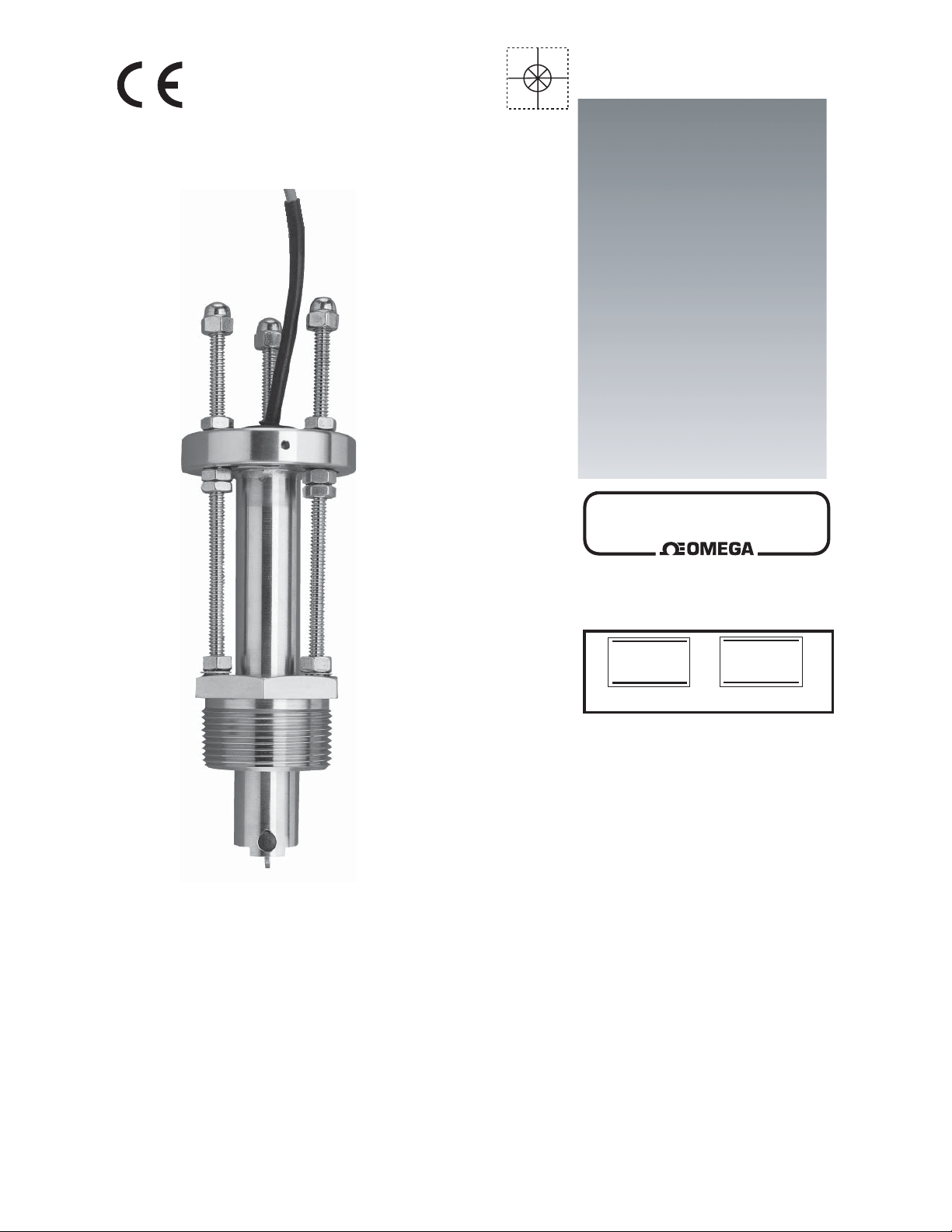
FP-2540/FP-3-1500 Series
Flow Sensors
Page 2

omega.com
TM
omega.com
®
OMEGAnet® Online Service Internet e-mail
www.omega.com info@omega.com
Servicing North America:
USA: One Omega Drive, P.O. Box 4047
ISO 9001 Certifi ed Stamford CT 06907-0047
TEL: (203) 359-1660 FAX: (203) 359-7700
e-mail: info@omega.com
Canada: 976 Bergar
Laval (Quebec) H7L 5A1
TEL: (514) 856-6928 FAX: (514) 856-6886
e-mail: info@omega.ca
For immediate technical or application assistance:
USA and Canada: Sales Service: 1-800-826-6342 / 1-800-TC-OMEGA
Customer Service: 1-800-622-2378 / 1-800-622-BEST
Engineering Service: 1-800-872-9436 / 1-800-USA-WHEN
TELEX: 996404 EASYLINK: 62968934 CABLE: OMEGA
®
®
®
Mexico: En Español: (001) 203-359-7803 e-mail: espanol@omega.com
FAX: (001) 203-359-7807 info@omega.com.mx
Servicing Europe:
Benelux: Postbus 8034, 1180 LA Amstelveen, The Netherlands
TEL: +31 (0)20 3472121 FAX: +31 (0)20 6434643
Toll Free in Benelux: 0800 0993344
e-mail: sales@omegaeng.nl
Czech Republic: Rudé arm
TEL: +420 (0)59 6311899 FAX: +420 (0)59 6311114
Toll Free: 0800-1-66342 e-mail: info@omegashop.cz
France: 11, rue Jacques Cartier, 78280 Guyancourt, France
TEL: +33 (0)1 61 37 29 00 FAX: +33 (0)1 30 57 54 27
Toll Free in France: 0800 466 342
e-mail: sales@omega.fr
Germany/Austria: Daimlerstrasse 26, D-75392 Deckenpfronn, Germany
TEL: +49 (0)7056 9398-0 FAX: +49 (0)7056 9398-29
Toll Free in Germany: 0800 639 7678
e-mail: info@omega.de
United Kingdom: One Omega Drive, River Bend Technology Centre
ISO 9002 Certifi ed Northbank, Irlam, Manchester
M44 5BD United Kingdom
TEL: +44 (0)161 777 6611 FAX: +44 (0)161 777 6622
Toll Free in United Kingdom: 0800-488-48
e-mail: sales@omega.co.uk
.
dy 1868, 733 01 Karvin. 8
It is the policy of OMEGA to comply with all worldwide safety and EMC/EMI regulations that apply. OMEGA is
constantly pursuing certifi cation of its products to the European New Approach Directives. OMEGA will add the CE
mark to every appropriate device upon certifi cation.
The information contained in this document is believed to be correct, but OMEGA Engineering, Inc. accepts
no liability for any errors it contains, and reserves the right to alter specifi cations without notice.
WARNING: These products are not designed for use in, and should not be used for, patient-connected applications.
Page 3
Omega FP-2540/FP-3-1500 Series
SAFETY INSTRUCTIONS
1. Do not remove from pressurized lines.
2. Do not exceed maximum temperature/pressure specifi cations.
3. Wear safety goggles or faceshield during installation/service.
4. Do not alter product construction.
5. Apply sealant or PTFE tape to sensor threads, inspecting threads to ensure integrity.
Do not install a sensor with damaged threads.
Pipe fi ttings MUST be installed by a certifi ed welder only. Omega will not assume liability of any kind for improper fi tting
installations.
Omega FP-3-1500 Series Hot-Tap sensor specifi cations and limitations depend on the lowest maximum rating of the
components associated with the system. If a ball valve, a component of the system, is rated at a maximum 100 psi @ 175°F,
the entire system's maximum pressure/temperature rating is limited to 100 psi @ 175°F. All higher maximum specifi cations
MUST yield to the component with the lowest maximum specifi cation.
Maximum Operating Pressure/Temperature:
• 17 bar (250 psi) @ 82°C (180°F) with standard FPM sensor fi tting O-rings.
• 17 bar (250 psi) @ 100°C ( 212°F) with optional EPR sensor fi tting O-rings.
Inlet
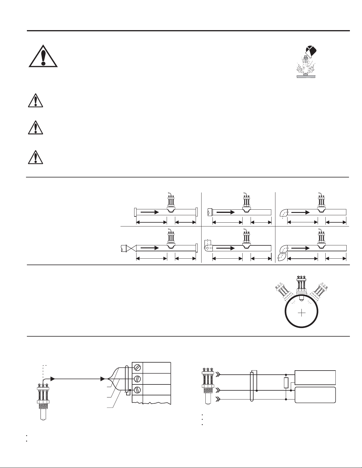
1. Location of Fitting
Recommended sensor upstream/
downstream
mounting requirements.
Flange
10x I.D. 5x I.D.
Outlet
Reducer
15x I.D. 5x I.D.
2 x 90° Elbow
3 dimensions
Valve/Pump
50x I.D. 5x I.D.
40x I.D. 5x I.D.
2. Sensor Mounting Position
Vertical mounting is recommended for best overall performance. Mount at a maximum of 30°
when air bubbles are present. DO NOT mount on the bottom of the pipe when sediments are
present.
3. Sensor Wiring
Omega FPM Series Instruments
Other Brands
90° Elbow
20x I.D. 5x I.D.
2 x90° Elbow
25x I.D. 5x I.D.
0°
-
30°
Process Pipe
+30°
1/2 in. NPT conduit port
Black (5 to 24 VDC)
Blk, sensor
power
Red, freq.
input
Shld,
Gnd
Red (signal out)
Silver (DC return)
Use 2-conductor shielded cable for cable extensions up to 300m (1000 ft.)
Maintain cable shield through splice.
instrument
black
silver
red
pull-up resistor required (10 kΩ recommended).
Use 2-conductor shielded cable for cable extensions up to 300m (1000 ft.)
Maintain cable shield through splice.
10 kΩ
+
-
Gnd.
Input
5 to 24
VDC
Other
instrument
1
Page 4
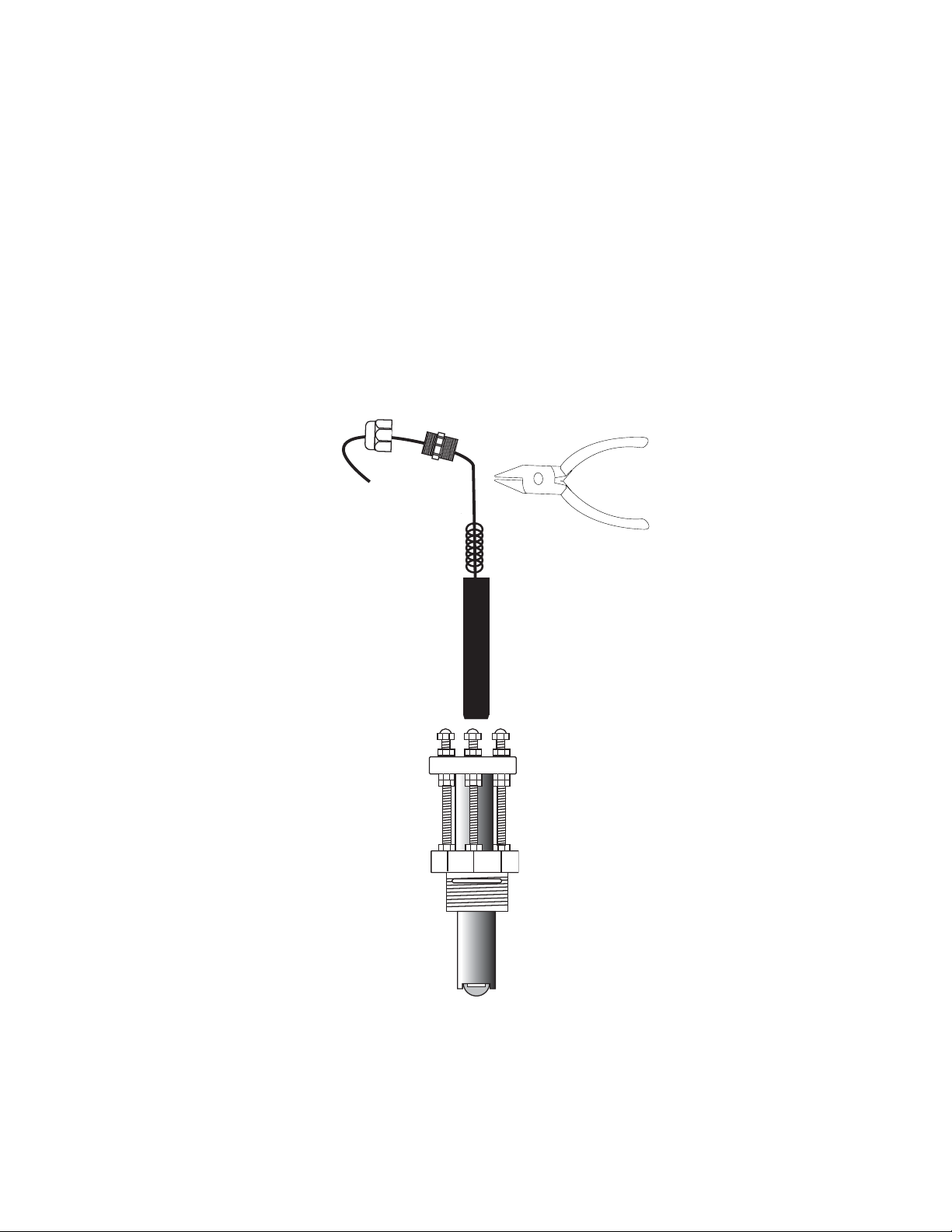
4. Electronics Module Installation and Removal
The electronics module of this sensor can be replaced without removing the steel sensor body from the line.
1. Loosen liquid tight connector cap.
2. Loosen liquid tight connector compression fi tting from sensor body.
3. Grasp the electronics at the rubber strain relief (do not pull on cable) and pull fi rmly.
To reinstall the electronics module:
• Insert module into sensor housing, making sure module is fully seated. Electronic pick-up module tip must bottom-out in the sensor
housing.
• Replace the liquid tight connector assembly.
To install the cable inside protective conduit, remove the liquid tight connector completely. Thread 1/2 in. conduit into top of sensor body.
Liquid Tight Connector-
Liquid Tight Connector-Cap
Compression Fitting
w/ 1/2 in. NPT threads
Grip the electronics
module at rubber
strain relief
1/2 in. NPT Threads
Electronics Module
FP-2540-EM (for Standard sensor)
FP-3-1500-EM (for Hot-tap sensor)
2
Page 5
5. Installation
The following items are required to properly install Omega FP-2540/FP-3-1500 series Sensors.
5.1 Hardware, Standard Sensor
• Female pipe fi tting (weld-on or saddle) with 1.5 in. NPT or ISO 7/1-Rc 1.5 threads
• 32 mm (1.25 in.) diameter drill
• Pipe thread sealant
• Tape measure
5.2 Hardware, Hot-Tap Sensor
The Hot-Tap sensor requires all the standard sensor items plus:
• Hot-Tap drilling machine (e.g., Mueller drilling machine or equivalent)
• Female ball or gate valve (full port only) with 1.5 in. NPT or ISO 7/1-Rc 1.5 threads
• Male pipe nipple, 32 x 50 mm (1.5 x 2 in.) with 1.5 in. NPT or ISO 7/1-R 1.5 threads
• Hot-Tap installation tool (purchased separately)
5.3 Standard Fitting Installation
A. Depressurize and drain pipe.
B. Wearing safety face protection, drill a 32 mm (1.25 in.) diameter hole in the
pipe.
C. Install the pipe fi tting of the outside of the pipe according to the manufacturer's
instructions. Failure to follow these instructions may result in serious bodily
injury and/or product failure.
pipe
sensor
fitting
process
pipe
fitting
D. Remove sensor fi tting from sensor assembly.
E. Thread sensor fi tting into pipe fi tting. (Fig. 1)
5.4 Hot-Tap Fitting Installation
A. Install the pipe fi tting on the outside diameter of the pipe according to the manufacturer's instructions. Failure to follow these
instructions may result in serious bodily injury and/or product failure.
B. Install the pipe nipple and isolation valve (ball or gate valve) onto the external pipe fi tting using pipe sealant on the
threads. (Fig. 2)
C. Wearing safety face protection, install an appropriate hole cutting tool per manufacturer's instructions (e.g., Mueller
drilling machine) with a 32 mm (1.25 in.) drill onto the top of the isolation valve, ensuring a tight fi t. Use the
recommended drill bit size or damage to the isolation valve may occur.
D. Open the isolation valve and insert the drill through the valve and cut the sensor clearance hole. After the hole is cut, withdraw the
drill from the isolation valve and close the valve. Remove the drilling machine per manufacturer's instructions. (Fig. 3)
pipe sealant recommended
Fig. 1
E. Install the sensor fi tting/bleed valve into the top of the isolation valve. Make sure the bleed valve clears the handle of the isolation
valve during operation.
sensor fitting
bleed valve
make sure
bleed valve
clears isolation
valve handle
Fig. 2
customer supplied
ball or gate valve
customer supplied
nipple: 32 x 50 mm
(1.25 x 2 in.) long
process pipe (side view)
Fig. 3
process pipe
3
Page 6

5.5 Calculating the H Dimension
Before installing the sensor some critical dimensions must be
established. The rotor shaft must be located 10% inside the pipe
I.D. to ensure accurate calibration capability. To accomplish this,
the "H" dimension is measured from the outside surface of the
pipe to the bottom of the sensor fl ange.
"H" dimensions for standard pipes are listed below.
For non-standard pipe dimensions, calculate the "H" dimension
using the formula below, based on the pipe's wall thickness and
inside diameter (id).
correct
wall
thickness
5
4
3
2
1
A
6
5
4
3
2
1
B
incorrect
6
5
5
4
4
3
3
2
2
1
1
A
B
6
5
5
4
4
3
3
2
2
1
1
A
B
pipe I.D.
H dimension formula
Calculate for a: Standard sensor Hot-tap sensor
Start with: 5.23 in. 15.39 in.
Subtract: wall thickness wall thickness
now subtract 10% of id 10% of id
The fi nal result: H H
Standard Sensors (2541, 2542)
Wrought Steel Pipe Per ANSI 36.10
NPS SCH 40 SCH 80 STD XS
inches inches inches inches inches
1½ 4.924 4.880 4.924 4.880
2 4.869 4.818 4.869 4.818
2½ 4.780 4.722 4.780 4.722
3 4.707 4.640 4.707 4.640
3½ 4.649 4.576 4.649 4.576
4 4.590 4.510 4.590 4.510
5 4.467 4.374 4.467 4.374
6 4.344 4.222 4.344 4.222
8 4.110 3.968 4.110 3.968
10 3.863 3.680 3.863 3.755
12 3.630 3.405 3.655 3.555
14 3.480 3.230 3.530 3.430
16 3.230 2.955 3.330 3.230
18 2.980 2.680 3.130 3.030
20 2.755 2.405 2.930 2.830
22 ----- 2.130 2.730 2.630
24 2.280 1.855 2.530 2.430
Use the 6 inch ruler to measure the pipe id and wall thickness up
to 5 inches (standard sensors only). for Hot-Tap installations, we
assume the pipe dimensions are known)
Pipe wall thickness: __________ Pipe id: ___________
Standard Sensors (2541, 2542)
Stainless Steel Pipe Per ANSI B36.19
NPS SCH 5S SCH10S SCH40S SCH 80S
inches inches inches inches inches
1½ 4.988 4.953 4.924 4.880
2 4.940 4.905 4.869 4.818
2½ 4.876 4.847 4.780 4.722
3 4.814 4.784 4.707 4.640
3½ 4.764 4.734 4.649 4.576
4 4.714 4.684 4.590 4.510
5 4.586 4.567 4.467 4.374
6 4.480 4.460 4.344 4.222
8 4.280 4.249 4.110 3.968
10 4.048 4.023 3.863 3.755
12 3.830 3.811 3.655 3.555
14 3.705 3.680 ----- ----16 3.498 3.480 ----- ----18 3.298 3.280 ----- ----20 3.080 3.056 ----- ----22 2.880 2.856 ----- ----24 2.656 2.630 ----- -----
Hot-Tap Sensors (FP-3-1500-2B, FP-3-1500-2M)
Wrought Steel Pipe Per ANSI 36.10
NPS SCH 40 SCH 80 STD XS
inches inches inches inches inches
1½ 15.084 15.040 15.084 15.040
2 15.029 14.978 15.029 14.978
2½ 14.940 14.882 14.940 14.882
3 14.867 14.800 14.867 14.800
3½ 14.809 14.736 14.809 14.736
4 14.750 14.670 14.750 14.670
5 14.627 14.534 14.627 14.534
6 14.534 14.382 14.534 14.382
8 14.270 14.128 14.270 14.128
10 14.023 13.840 14.023 13.915
12 13.790 13.565 13.815 13.715
14 13.640 13.390 13.690 13.590
16 13.390 13.115 13.490 13.390
18 13.140 12.840 13.290 13.190
20 12.915 12.565 13.090 12.990
22 ----- 12.290 12.890 12.790
24 12.440 12.015 12.690 12.590
4
Hot-Tap Sensors (FP-3-1500-2B, FP-3-1500-2M)
Stainless Steel Pipe Per ANSI B36.19
NPS SCH 5S SCH 10S SCH 40S SCH 80S
inches inches inches inches inches
1 ½ 15.148 15.113 15.084 15.040
2 15.101 15.065 15.029 14.978
2 ½ 15.036 15.007 14.940 14.882
3 14.974 14.944 14.867 14.800
3 ½ 14.924 14.894 14.809 14.736
4 14.874 14.844 14.750 14.670
5 14.747 14.727 14.627 14.534
6 14.640 14.620 14.534 14.382
8 14.440 14.409 14.270 14.128
10 14.208 14.183 14.023 13.915
12 13.990 13.971 13.815 13.715
14 13.865 13.840 ----- ----16 13.658 13.640 ----- ----18 13.458 13.440 ----- ----20 13.240 13.216 ----- ----22 13.040 13.016 ----- ----24 12.816 12.790 ----- -----
(-----) unavailable
Page 7

5.6 Standard Sensor Installation
A. Thread one hex nut onto each of the three threaded rods
included in package. Install threaded rod with a lock washer
onto the sensor fi tting. Secure rods in place by tightening each
hex nut against the sensor fi tting. (Fig. 4)
Fig. 4
hex nut
Lock washer
B. Thread one jam nut and lower hex nut onto each threaded
rod so that the top surface of each nut is at the proper "H"
dimension for your pipe. Secure each hex nut with a jam nut.
(Fig. 5)
sensor fitting
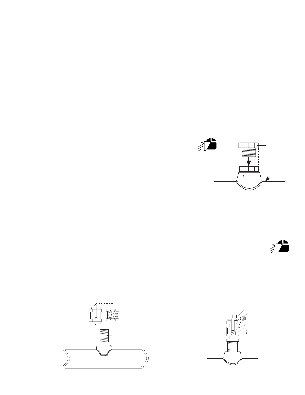
C. Insert the fl ow sensor into the sensor fi tting, making sure the
alignment hole on the sensor fl ange is pointing downstream.
D. Place the alignment rod in the alignment hole
on the sensor fl ange. Align the fl ange so rod is
parallel to the process pipe. (Fig. 6)
E. Thread upper hex nuts with lock washers until they
contact the sensor fl ange and tighten. Check for
proper "H" dimension and readjust if necessary.
(Fig. 7)
sensor
flange
flow direction
alignment
rod
process pipe
(top view)
The flow sensor alignment rod MUST be
parallel to the process pipe as shown.
Fig. 6
5.7 Hot-Tap Sensor Installation
A. Thread one hex nut onto each of the three threaded rods included in package. Install threaded
rod with a lock washer onto the sensor fi tting. Secure rods in place by tightening each hex nut
against the sensor fi tting. (Fig. 8)
Fig. 5
"H"
"H"
sensor
flange
jam nuts
sensor
fitting
Fig. 7
FLOW
lower hex nuts
(3/16 x 1/4-20)
jam nuts
(5/32 x 1/4-20)
hex nut &
lock washer
sensor fitting
process pipe
cap nuts
upper hex nuts
& lockwashers
lower hex nuts
female pipe fitting
process
pipe wall I.D.
B. Thread one jam nut and lower hex nut onto each threaded rod so that the top surface of each
nut is 359 mm (14.14 in.) from the top surface of the sensor fi tting. Secure each hex nut with
a jam nut. (Fig. 9)
CAUTION: This setting is critical to ensure an adequate sensor seal and to
prevent the rotor from hitting the isolation valve orifi ce during installation.
C. Wipe the sensor body with a dry, clean cloth. Orient the alignment hole on the sensor fl ange
to point downstream. Place the slotted fl ange over the threaded rods. Lower the sensor into
the fi tting until the sensor fl ange rests on the lower hex and jam nuts.
D. Secure the sensor with lock washers and upper hex nuts on the top of the fl ange. Before
tightening, align the sensor fl ange so that the alignment rod is parallel and level with the
process pipe. (Fig. 10 & Fig. 11)
E. Make sure the bleed valve is closed (full clockwise position).
lower hex nuts
(3/16 x 1/4-20)
jam nuts
(5/32 x 1/4-20)
359 mm
(14.14 in.)
sensor
fitting
sensor
flange
flow direction
alignment
rod
process pipe
(top view)
The flow alignment rod MUST be
parallel to the process pipe as shown.
sensor flange
lower hex nut
and jam nuts
18 inch
threaded rods
sensor
fitting
Fig. 8
hex nut
Lock washer
sensor fitting
Upper hex nuts
(3/16 x 1/4-20)
1/4 in. lock
washers
alignment rod
359 mm (14.14 in)
bleed valve
Fig. 9
UNDER PRESSURE!
Fig. 10
Fig. 11
direction
of flow
process pipe (side view)
5
Page 8

Hot-Tap Sensor Installation - Continued
F. Thread protector plate hex nuts onto each of the three
threaded rods. Adjust each hex nut to a height of
approximately 25 mm (1 in.) from the top of each rod.
Remove the black plastic cable grommet in top of sensor
with a screwdriver. Slide the grommet up the cable away
from sensor. (Fig. 12)
protector plate
cap nuts
25mm
(1.0 in.)
protector plate
removed during
sensor installation
protector plate
hex nut (3/16 x
1/4-20)
cable
grommit
Fig. 12
G. Position the installation tool bearing plate by rotating it so that it is approximately 40 mm (1.6 in.) from the swivel mount. Mount
the installation tool by placing the threaded rods through the holes in the tool's bearing plate, resting the bearing plate on top of
the protector plate hex nuts. Make sure the swivel mount's ears are mounted between the threaded rods (not over the rods).
Install the bearing plate cap nuts. Tighten the bearing plate cap nuts to secure the installation tool in place. (Fig. 13)
H. Align the sensor cable with the swivel mount cable port to prevent cable pinching. Use a 3/8 inch wrench or socket to turn the
installation tool shaft clockwise until it is seated in the hole at the top of the sensor fl ange.
I. Wearing safety face protection, slowly open the isolation valve to the full open position. Loosen the lower hex and
jam nuts and move them to the proper "H" dimension. Turn the installation tool shaft clockwise until the sensor fl ange
contacts the lower hex and jam nuts. Thread the upper hex nuts down until they contact the sensor fl ange. Tighten the
upper hex nuts to secure the sensor. (Fig. 14)
J. Remove cap nuts and withdraw the installation tool. Be careful to not damage cable. Snap cable grommet into top of sensor
and replace protector plate and cap nuts. (Fig. 15)
Fig. 14
Fig. 13
cap nuts
protector plate
hex nuts
sensor
cable
installation tool
threaded shaft
bearing plate
swivel mount
w/cable port
sensor flange
installation
tool shaft
upper hex nuts
"H"
cap nuts
alignment rod
lower hex nuts
jam nuts
isolation valve
Fig. 15
protector plate
cap nuts
protector plate
protector plate
sensor body
hex nut
direction
of flow
6. Standard Sensor Removal
To remove the sensor from a depressurized empty pipe, simply remove the cap nuts and upper hex nuts located above the sensor
fl ange. Pull up on sensor fl ange with twisting motion.
6
Page 9

r
7. Hot-Tap Sensor Removal
To remove the Hot-Tap sensor safely from a pressurized active pipe, the entire installation
process must be reversed.
A. Remove the cap nuts, protector plate, protector plate hex nuts, and sensor cable grommet.
(Fig. 16)
372 mm
(14.6 in.)
installation tool
threaded shaft
upper hex nuts
and lock washers
sensor flange
lower hex and
jam nuts
B. Thread installation tool in place and secure bearing plate in place of sensor protector plate.
(Fig. 17)
C. Turn shaft of installation tool clockwise to lower tool into opening in sensor fl ange. Guide
cable into the port to prevent damage.
Fig. 16
protector plate
cap nuts
protector plate
protector plate
hex nut
Fig. 17
UNDER PRESSURE!
process pipe (side view)
D. Wearing safety face protection, loosen the upper hex nuts and raise to 372 mm (14.6 in.) from top of sensor fi tting to
bottom of upper hex nuts/lock washers. CAUTION! This measurement is critical to maintain watertight seal in
sensor while allowing clearance to close the isolation valve.
E. Wearing safety face protection, turn the installation tool shaft
counterclockwise to withdraw sensor until the sensor fl ange contacts
the upper hex nuts. (Fig. 18)
F. Raise one lower hex and jam nut to bottom of sensor fl ange.
cap nuts
protector plate
hex nuts
G. Close isolation valve, remove bearing plate and tool.
upper hex nuts
H. Wearing safety face protection, cover the bleed valve with suitable
protection (rag, towel, etc.) and open the bleed valve (ccw rotation)
to relieve internal pressure. Pull sensor up until bleed valve purges
some fl uid (indicating sensor is past 1st o-ring seal inside sensor
fi tting).
sensor fitting
isolation valve
installation tool
threaded shaft
installation tool
bearing plate
swivel mount
w/cable port
sensor flange
1 lower hex nut
and jam nut
sensor body
CAUTION: In case of a leaky isolation valve, the sensor will be under a slight
Fig. 18
amount of pressure. Care should be taken when removing the sensor.
Use the bleed valve to relieve this pressure taking care not to spray fl uid on yourself or others.
Sensor can now be safely removed. When reinstalling the sensor: leave one lower hex nut in position to guide sensor to proper
isolation valve clearance height before opening isolation valve. Return to "H" dimension height after valve is opened.
8. Maintenance
Your sensor requires little or no maintenance of any kind, with the exception of an occasional sensor/paddlewheel cleaning.
9. Sensor Parts
2541 Sensor Assemblies Accessories
Order no. Sensor type Fitting type Order no. Description
FP-2541 Standard 1.5 in. NPT FP-3-1500-302 Hot-Tap installation tool
FP-2542 Standard IS0 7/1-R 1.5 FP-3-2540-321 Rotor kit w/Tungsten Carbide pin Fluoroloy-B bearings, 316 SS retainers
FP-3-1500-2B Hot-Tap 1.5 in. NPT FP-3-2540-322 Rotor kit w/316 SS pin, Fluoroloy-B bearings, 316 ss retainers
FP-3-1500-2M Hot-Tap IS0 7/1-R 1.5 FPP-1220-0021* Standard FPM O-ring for sensor fi tting
FPP-1224-0021* Optional EPR O-ring for sensor fi tting
FP-2540-EM Replacement electronics module, standard
FP-3-1500-EM Replacement electronics module, hot-tap
M-2346 Instruction manual
___________
*One O-ring required for standard sensor
Two O-rings required for Hot-Tap sensor
retainer retaine
bearing
rotor pin
bearing
rotor
7
Page 10

10. K-Factors (Stainless Steel, Wrought Steel & Plastic Pipe)
SCH 5S STAINLESS STEEL PIPE
PER ANSI B36.19
K-Factor K-Factor
PIPE PULSES/ PULSES/
SIZE U.S. GAL LITER
1½ in. 115.1900 30.433
2 in. 71.3960 18.863
2 ½ in. 49.263 13.015
3 in. 32.636 8.622
3 ½ in. 24.537 6.483
4 in. 19.1350 5.055
5 in. 12.4490 3.289
6 in. 8.4602 2.235
8 in. 4.9137 1.298
10 in. 3.1228 0.825
12 in. 2.1772 0.575
14 in. 1.7977 0.475
16 in. 1.3717 0.362
18 in. 1.0855 0.287
20 in. 0.8801 0.233
22 in. 0.7293 0.193
24 in. 0.6141 0.162
SCH 10S STAINLESS STEEL PIPE
PER ANSI B36.19
K-Factor K-Factor
PIPE PULSES/ PULSES/
SIZE U.S. GAL LITER
1½ in. 127.930 33.799
2 in. 76.439 20.195
2 ½ in. 51.946 13.724
3 in. 34.174 9.029
3½ in. 25.571 6.756
4 in. 19.829 5.239
5 in. 12.730 3.363
6 in. 8.5938 2.270
8 in. 5.0062 1.323
10 in. 3.1793 0.840
12 in. 2.1914 0.579
14 in. 1.8147 0.479
16 in. 1.3798 0.365
18 in. 1.0912 0.288
20 in. 0.8855 0.234
22 in. 0.7334 0.194
24 in. 0.6175 0.163
XS WROUGHT STEEL PIPE
PER ANSI B36.10
K-Factor K-Factor
PIPE PULSES/ PULSES/
SIZE U.S. GAL LITER
1 ½ in. 161.79 42.745
2 in. 95.713 25.287
2 ½ in. 66.686 17.618
3 in. 42.986 11.357
3 ½ in. 31.983 8.450
4 in. 24.668 6.517
5 in. 15.480 4.090
6 in. 10.691 2.825
8 in. 5.9733 1.578
10 in. 3.6489 0.964
12 in. 2.4548 0.649
14 in. 1.9931 0.527
16 in. 1.4970 0.396
18 in. 1.1727 0.310
20 in. 0.9388 0.248
22 in. 0.7685 0.203
24 in. 0.6446 0.170
STD WROUGHT STEEL PIPE
PER ANSI B36.10
K-Factor K-Factor
PIPE PULSES/ PULSES/
SIZE U.S. GAL LITER
1 ½ in. 140.030 36.996
2 in. 83.240 21.992
2 ½ in. 59.034 15.597
3 in. 38.674 10.218
3 ½ in. 28.752 7.596
4 in. 22.226 5.872
5 in. 14.061 3.715
6 in. 9.5160 2.514
8 in. 5.4523 1.441
10 in. 3.4507 0.912
12 in. 2.3318 0.616
14 in. 1.9186 0.507
16 in. 1.4483 0.383
18 in. 1.1390 0.301
20 in. 0.9146 0.242
22 in. 0.7506 0.198
24 in. 0.6311 0.167
SCH 40S STAINLESS STEEL PIPE
PER ANSI B36.19
K-Factor K-Factor
PIPE PULSES/ PULSES/
SIZE U.S. GAL LITER
1 ½ in. 140.030 36.996
2 in. 83.240 21.992
2 ½ in. 59.034 15.597
3 in. 38.675 10.218
3 ½ in. 28.752 7.596
4 in. 22.226 5.872
5 in. 14.061 3.715
6 in. 9.5160 2.514
8 in. 5.4523 1.441
10 in. 3.4507 0.912
12 in. 2.3318 0.616
SCH 40 STAINLESS STEEL PIPE
14 in. 1.9556 0.517
16 in. 1.4970 0.396
18 in. 1.1900 0.314
20 in. 0.9577 0.253
24 in. 0.6662 0.176
SCH 40 WROUGHT STEEL PIPE
PER ANSI B36.10
K-Factor K-Factor
PIPE PULSES/ PULSES/
SIZE U.S. GAL LITER
1 ½ in. 140.030 36.996
2 in. 83.240 21.992
2- ½ in. 59.034 15.597
3 in. 38.674 10.218
3 ½ in. 28.752 7.596
4 in. 22.226 5.872
5 in. 14.061 3.715
6 in. 9.5160 2.514
8 in. 5.4523 1.441
10 in. 3.4507 0.912
12 in. 2.3517 0.621
14 in. 1.9556 0.517
16 in. 1.4970 0.396
18 in. 1.1900 0.314
20 in. 0.9577 0.253
24 in. 0.6662 0.176
K-factors are listed in U.S. gallons and in liters. Conversion formulas for other engineering units are
listed below.
• K = 60/A
The K-factor is the number of pulses generated by the 2540 paddlewheel per unit of liquid in a
specifi c pipe size.
To convert multiply
K from: to: K by:
U.S. gallons cubic feet 7.479
U.S. gallons cubic inches 0.00433
U.S. gallons cubic meters 263.85
U.S. gallons pounds of water 0.120
U.S. gallons acre feet 325853
U.S. gallons Imperial gallons 1.201
8
Page 11

K-Factors (Stainless Steel, Wrought Steel & Plastic Pipe) continued
SCH 80S STAINLESS STEEL PIPE
PER ANSI B36.19
K-Factor K-Factor
PIPE PULSES/ PULSES/
SIZE U.S. GAL LITER
1 ½ in. 161.790 42.745
2 in. 95.710 25.287
2 ½ in. 66.686 17.618
3 in. 42.986 11.357
3 ½ in. 31.983 8.450
4 in. 24.668 6.517
5 in. 15.480 4.090
6 in. 10.691 2.825
8 in. 5.9733 1.578
10 in. 3.6489 0.964
12 in. 2.4548 0.649
SCH 80 STAINLESS STEEL PIPE
14 in. 2.1557 0.570
16 in. 1.6444 0.434
18 in. 1.3036 0.344
20 in. 1.0533 0.278
22 in. 0.8689 0.230
24 in. 0.7335 0.194
SCH 80 WROUGHT STEEL PIPE
PER ANSI B36.10
K-Factor K-Factor
PIPE PULSES/ PULSES/
SIZE U.S. GAL LITER
1 ½ in. 161.790 42.745
2 in. 95.713 25.287
2 ½ in. 66.686 17.618
3 in. 42.986 11.357
3 ½ in. 31.983 8.450
4 in. 24.668 6.517
5 in. 15.480 4.090
6 in. 10.691 2.825
8 in. 5.9733 1.578
10 in. 3.7983 1.004
12 in. 2.6198 0.692
14 in. 2.1557 0.570
16 in. 1.6444 0.434
18 in. 1.3036 0.344
20 in. 1.0533 0.278
22 in. 0.8689 0.230
24 in. 0.7335 0.194
SCH 40 Plastic pipe per ASTM-D-1785
K-Factor K-Factor
PIPE PULSES/ PULSES/
SIZE U.S. GAL LITER
1 ½ in. 139.850 36.948
2 in. 82.968 21.920
2 ½ in. 60.194 15.903
3 in. 39.513 10.439
3 ½ in. 29.295 7.740
4 in. 22.565 5.962
5 in. 14.308 3.780
6 in. 9.8630 2.606
8 in. 5.6400 1.490
10 in. 3.4476 0.911
12 in. 2.3786 0.628
SCH 80 Plastic pipe per ASTM-D-1785
K-Factor K-Factor
PIPE PULSES/ PULSES/
SIZE U.S. GAL LITER
1 ½ in. 162.290 42.877
2 in. 97.186 25.677
2 ½ in. 68.559 18.113
3 in. 43.870 11.590
3 ½ in. 32.831 8.674
4 in. 25.250 6.671
5 in. 15.835 4.184
6 in. 11.041 2.917
8 in. 6.2877 1.661
10 in. 3.8529 1.018
12 in. 2.6407 0.698
9
Page 12

11. Specifi cations
General Data
Flow velocity range: 0.1 to 6 m/s (0.3 to 20 ft/s)
Linearity: ±1% of full range
Repeatability: ±0.5% of full range
Pipe range:
• Standard version: 38 to 610 mm (1.5 to 24 in.)
• Hot-Tap version: 38 to 914 mm (1.5 to 36 in.)
Sensor fi tting options: 316 SS with 1.5 in. NPT threads,
OR 316 SS with IS0 7/1-R 1.5 threads
Cable length: 7.6 m (25 ft.), can splice up to
300 m (1000 ft.)
Cable type: 2-conductor twisted-pair with shield
Fluid Conditions
Maximum operating pressure/temperature:
• Sensor with standard FPM sensor fi tting O-rings:
17 bar (250 psi) @ 82 °C (180 °F)
• Sensor with optional EPR sensor fi tting O-rings:
17 bar (250 psi) @ 100 °C (212 °F)
Wetted Materials
Sensor body: 316 stainless steel
Sensor fi tting: 316 stainless steel
Sensor fi tting O-rings: Standard Viton®, optional
EPR
Rotor: CD4MCu stainless steel
Rotor shaft: Tungsten carbide (standard)
316 stainless steel (option)
Shaft retainers (2): 316 stainless steel
Rotor bearings (2): Fluoroloy B®
Electrical Data
Supply voltage: 5 to 24 VDC
Supply current: 1.5 mA max.
Output type: Open collector, sinking
Output current: 10.0 mA max.
7.5 m (25 ft.)
integral cable
Adjustable
length
O-ring
seal (1)
Caution: The OMEGA FP-3-1500 Series Hot-Tap
system's overall specifi cations and limitations depend
on the lowest maximum rating of the components
associated with the system. In other words, the HotTap system is only as strong as its weakest link. For example,
a ball valve, a component of the system, is rated at a maximum
100 psi @ 175 °F, limiting the entire system's maximum pressure/
temperature rating to 100 psi @ 175 °F. All higher maximum
specifi cations MUST yield to the component with the lowest
maximum specifi cation.
Note: Pressure/temperature specifi cations refer to sensor
performance in water. Certain chemical limitations may apply.
Chemical compatibility should be verifi ed.
64 mm (2.5 in.) dia.
64 mm (2.5 in.) dia.
7.6 m
(25 ft.)
127 mm
(5.0 in.)
Sensor fitting:
1.5 in. NPT or
ISO 7/1-R 1.5
thread
cable
O-ring
seals (2)
Adjustable
length
457 mm
(18 in.)
Bleed
valve
Sensor fitting:
1.5 in. NPT or
ISO 7/1-R 1.5
thread
24 mm (0.94 in.) dia.
Standard Sensor Dimensions:
• FP-2541 = 1.5 in. NPT fi tting
• FP-2542 = ISO 7/1-R 1.5 fi tting
24 mm (0.94 in.) dia.
Hot-Tap Sensor Dimensions:
• FP-3-1500-2B = 1.5 in. NPT fi tting
• FP-3-1500-2M = ISO 7/1-R 1.5 fi tting
10
Page 13

11
Page 14

12
Page 15

SA
MAD E
IN
IN
USA
WARRANTY/DISCLAIMER
OMEGA ENGINEERING, INC. warrants this unit to be free of defects in materials and workmanship for a period
of 13 months from date of purchase. OMEGA’s WARRANTY adds an additional one (1) month grace period to
the normal one (1) year product warranty to cover handling and shipping time. This ensures that OMEGA’s
customers receive maximum coverage on each product.
If the unit malfunctions, it must be returned to the factory for evaluation. OMEGA’s Customer Service
Department will issue an Authorized Return (AR) number immediately upon phone or written request.
Upon examination by OMEGA, if the unit is found to be defective, it will be repaired or replaced at no
charge. OMEGA’s WARRANTY does not apply to defects resulting from any action of the purchaser,
including but not limited to mishandling, improper interfacing, operation outside of design limits,
improper repair, or unauthorized modification. This WARRANTY is VOID if the unit shows evidence of
having been tampered with or shows evidence of having been damaged as a result of excessive corrosion;
or current, heat, moisture or vibration; improper specification; misapplication; misuse or other operating
conditions outside of OMEGA’s control. Components which wear are not warranted, including but not
limited to contact points, fuses, and triacs.
OMEGA is pleased to offer suggestions on the use of its various products. However,
OMEGA neither assumes responsibility for any omissions or errors nor assumes liability for
any damages that result from the use of its products in accordance with information provided
by OMEGA, either verbal or written. OMEGA warrants only that the parts manufactured by it
will be as specified and free of defects. OMEGA MAKES NO OTHER WARRANTIES OR
REPRESENTATIONS OF ANY KIND WHATSOEVER, EXPRESS OR IMPLIED, EXCEPT THAT OF
TITLE, AND ALL IMPLIED WARRANTIES INCLUDING ANY WARRANTY OF MERCHANTABILITY
AND FITNESS FOR A PARTICULAR PURPOSE ARE HEREBY DISCLAIMED. LIMITATION OF
LIABILITY: The remedies of purchaser set forth herein are exclusive, and the total liability of
OMEGA with respect to this order, whether based on contract, warranty, negligence,
indemnification, strict liability or otherwise, shall not exceed the purchase price of the
component upon which liability is based. In no event shall OMEGA be liable for
consequential, incidental or special damages.
CONDITIONS: Equipment sold by OMEGA is not intended to be used, nor shall it be used: (1) as a “Basic
Component” under 10 CFR 21 (NRC), used in or with any nuclear installation or activity; or (2) in medical
applications or used on humans. Should any Product(s) be used in or with any nuclear installation or activity,
medical application, used on humans, or misused in any way, OMEGA assumes no responsibility as set forth in
our basic WARRANTY / DISCLAIMER language, and, additionally, purchaser will indemnify OMEGA and hold
OMEGA harmless from any liability or damage whatsoever arising out of the use of the Product(s) in such a
manner.
RETURN REQUESTS/INQUIRIES
Direct all warranty and repair requests/inquiries to the OMEGA Customer Service Department. BEFORE RETURNING ANY PRODUCT(S) TO OMEGA, PURCHASER MUST OBTAIN AN AUTHORIZED RETURN (AR)
NUMBER FROM OMEGA’S CUSTOMER SERVICE DEPARTMENT (IN ORDER TO AVOID PROCESSING
DELAYS). The assigned AR number should then be marked on the outside of the return package and on any
correspondence.
The purchaser is responsible for shipping charges, freight, insurance and proper packaging to prevent breakage in transit.
FOR WARRANTY RETURNS, please have the
following information available BEFORE
contacting OMEGA:
1. Purchase Order number under which the product
was PURCHASED,
2. Model and serial number of the product under
warranty, and
3. Repair instructions and/or specifi c problems
relative to the product.
OMEGA’s policy is to make running changes, not model changes, whenever an improvement is possible. This affords our
customers the latest in technology and engineering.
OMEGA is a registered trademark of OMEGA ENGINEERING, INC.
© Copyright 2000 OMEGA ENGINEERING, INC. All rights reserved. This document may not be copied, photocopied, reproduced,
translated, or reduced to any electronic medium or machine-readable form, in whole or in part, without the prior written consent of
OMEGA ENGINEERING, INC.
FOR NON-WARRANTY REPAIRS,
consult OMEGA for
current repair charges. Have the following information
available BEFORE contacting OMEGA:
1. Purchase Order number to cover the COST of the
repair,
2. Model and serial number of the product, and
3. Repair instructions and/or specifi c problems
relative to the product.
Page 16

Where Do I Find Everything I Need for
Process Measurement and Control?
OMEGA…Of Course!
Shop online at www.omega.com
TEMPERATURE
Thermocouple, RTD & Thermistor Probes, Connectors, Panels & Assemblies
Wire: Thermocouple, RTD & Thermistor
Calibrators & Ice Point References
Recorders, Controllers & Process Monitors
Infrared Pyrometers
PRESSURE, STRAIN AND FORCE
Transducers & Strain Gages
Load Cells & Pressure Gages
Displacement Transducers
Instrumentation & Accessories
FLOW/LEVEL
Rotameters, Gas Mass Flowmeters & Flow Computers
Air Velocity Indicators
Turbine
Totalizers & Batch Controllers
/Paddlewheel Systems
pH/CONDUCTIVITY
pH Electrodes, Testers & Accessories
Benchtop
Controllers, Calibrators, Simulators & Pumps
Industrial pH & Conductivity Equipment
/Laboratory Meters
DATA ACQUISITION
Data Acquisition & Engineering Software
Communications-Based Acquisition Systems
Plug-in Cards for Apple, IBM & Compatibles
Datalogging Systems
Recorders, Printers & Plotters
HEATERS
Heating Cable
Cartridge & Strip Heaters
Immersion & Band Heaters
Flexible Heaters
Laboratory Heaters
ENVIRONMENTAL
MONITORING AND CONTROL
Metering & Control Instrumentation
Refractometers
Pumps & Tubing
Air, Soil & Water Monitors
Industrial Water & Wastewater Treatment
pH, Conductivity & Dissolved Oxygen Instruments
14
6-2540.090-OM (H-6/06) M-2346/0606
 Loading...