

Page 1
User’s Guide
omega.com
Shop online at
omega.com
TM
®
www.omega.com
e-mail: http://omegamanual.info
For latest information and
product manual visit
www.omegamanual.info.
ISO 9001
CERTIFIED
CORPORATE QUALIT Y
STAMFORD, CT
ISO 9002
CERTIFIED
CORPORATE QUALIT Y
MANCHESTER, UK
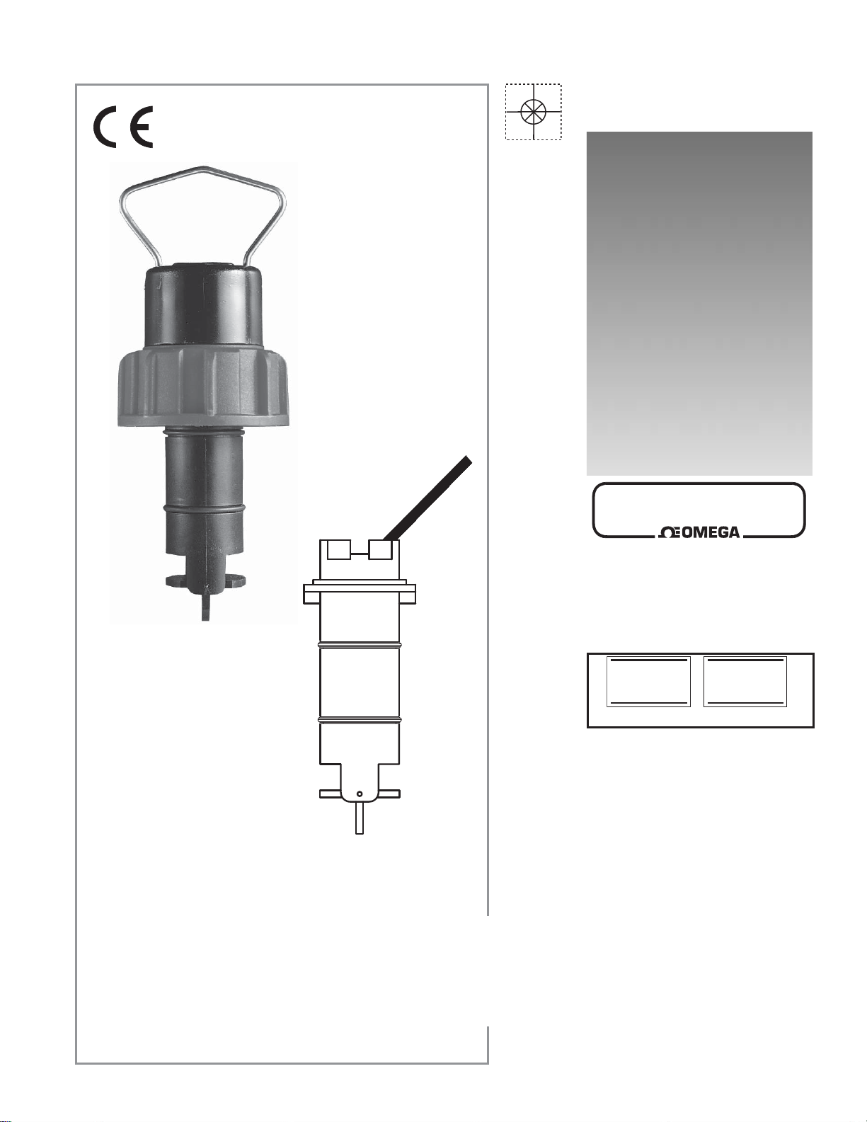
Paddlewheel Flow Sensors
Series: FMK-2536, FP-5100, FP-5300,
FP-5600, FP-8500, FP-8500A
Page 2

omega.com
omega.com
®
TM
OMEGAnet® Online Service
www.omega.com
Internet e-mail
info@omega.com
Servicing North America:
USA: One Omega Drive, P.O. Box 4047
ISO 9001 Certifi ed Stamford CT 06907-0047
TEL: (203) 359-1660 FAX: (203) 359-7700
e-mail: info@omega.com
Canada: 976 Bergar
Laval, Quebec H7L 5A1
TEL: (514) 856-6928 FAX: (514) 856-6886
e-mail: info@omega.ca
For immediate technical or application assistance:
USA and Canada: Sales Service: 1-800-826-6342 / 1-800-TC-OMEGA
Customer Service: 1-800-622-2378 / 1-800-622-BEST
Engineering Service: 1-800-872-9436 / 1-800-USA-WHEN
TELEX: 996404 EASYLINK: 62968934 CABLE: OMEGA
Mexico: En Español: (001) 203-359-7803 FAX: (001) 203-359-7807
info@omega.com.mx
e-mail: espanol@omega.com
®
®
®
Servicing Europe:
Benelux: Postbus 8034, 1180 LA Amstelveen, The Netherlands
TEL: +31 (0)20 3472121 FAX: +31 (0)20 6434643
Toll Free in Benelux: 0800 0993344
e-mail: sales@omegaeng.nl
Czech Republic: Rudé arm
TEL: +420 (0)59 6311899 FAX: +420 (0)59 6311114
Toll Free: 0800-1-66342
e-mail: info@omegashop.cz
France: 11, rue Jacques Cartier, 78280 Guyancourt, France
TEL: +33 (0)1 61 37 29 00 FAX: +33 (0)1 30 57 54 27
Toll Free in France: 0800 466 342
e-mail: sales@omega.fr
Germany/Austria: Daimlerstrasse 26, D-75392 Deckenpfronn, Germany
TEL: +49 (0)7056 9398-0 FAX: +49 (0)7056 9398-29
Toll Free in Germany: 0800 639 7678
e-mail: info@omega.de
United Kingdom: One Omega Drive, River Bend Technology Centre
ISO 9002 Certifi ed Northbank, Irlam, Manchester
M44 5BD United Kingdom
TEL: +44 (0)161 777 6611 FAX: +44 (0)161 777 6622
Toll Free in United Kingdom: 0800-488-48
e-mail: sales@omega.co.uk
.
dy 1868, 733 01 Karvin. 8
It is the policy of OMEGA to comply with all worldwide safety and EMC/EMI regulations that apply.
OMEGA is constantly pursuing certifi cation of its products to the European New Approach Directives.
OMEGA will add the CE mark to every appropriate device upon certifi cation.
The information contained in this document is believed to be correct, but OMEGA Engineering, Inc. accepts
no liability for any errors it contains, and reserves the right to alter specifi cations without notice.
WARNING: These products are not designed for use in, and should not be used for, patient-connected applications.
page 2 OMEGA Paddlewheel Flow Sensors
Page 3
OMEGA Paddlewheel Flow Sensors
40
80
120
160
200
3
6
8
11
14
0 40 80 120 160 200
-18 4
27
49
71 93
°F
°C
psi
bar
240
115
Low-Flow - PVDF
Low-Flow - Polypropylene
102 mm/
4.0 in.
-X0 or
-X1
-X0 = 152 mm/6.0 in.
-X1 = 185 mm/7.3 in.
Standard
7.6 m/25 ft
cable
included
26.7 mm/
1.05 in.
-X (0 thru 5)
Pipe Range:
1/2 to 4 in. -X0 = 104 mm/4.1 in.
5 to 8 in. -X1 = 137 mm/5.4 in.
10" and up -X2 = 213 mm/8.4 in.
1/2 to 4 in. -X3 = 297 mm/11.7 in.
5 to 8 in. -X4 = 332 mm/13.1 in.
10" and up -X5 = 408 mm/16.1 in.
Wet-tap
Lengths
1-1/4" NPSM
threaded cap
40
80
120
160
200
3
6
8
11
14
0 40 80 120 160 200
-18 4
27
49
71 93
°F
°C
psi
bar
240
115
Self-Powered - PVDF
Self-Powered - Polypropylene
Instructions for all versions of: Self-Powered Sensors (FP-5100, FP-5300 and FP-8500 Series) and
Low-Flow Sensors (FP-5600 and 8500A Series)
SAFETY INSTRUCTIONS
1. Depressurize and vent system prior to installation or removal.
2. Confi rm chemical compatibility before use.
3. DO NOT exceed maximum temperature/pressure specifi cations.
4. ALWAYS wear safety goggles or faceshield during installation/service.
5. DO NOT alter product construction.
1. Specifi cations
General Data
Flow Rate Range: Self-powered: 0.3 to 6 m/s (1 to 20 ft/s)
Low-fl ow: 0.1 to 6 m/s (0.3 to 20 ft/s)
Pipe Size Range: DN15 to DN900 (½ in. to 36 in.)
Linearity: ±1% of maximum range @ 25 °C (77 °F)
Repeatability: ±0.5% maximum range @ 25 °C (77 °F)
Cable Length: 7.6 m (25 ft) standard
Self-powered: 60 m (200 ft) maximum
Low-fl ow: 305 m (1000 ft) maximum
Cable Type: 2-conductor twisted pair w/shield (22 AWG)
Minimum Reynolds Number Required: 4500
Cap Material: Glass Filled Polypropylene
Self-powered: Red
Low-fl ow: Blue
Standards & Approvals
• Manufactured under ISO 9001 and ISO 14001
• CE
Wetted Materials
• Sensor Body: Glass fi lled Polypropylene (black) or PVDF
• O-Rings: FPM (Std), EPR (EPDM) or FFKM optional
• Pin: Titanium, Hastelloy-C or PVDF; other material
• Rotor: Black or natural PVDF; optional ETFE with or
Shipping Weight: -X0 0.454 kg (1 lb)
-X1 0.476 kg (1.04 lbs)
-X2 0.680 kg (1.50 lbs)
-X3 0.794 kg (1.75 lbs)
-X4 0.850 kg (1.87 lbs)
-X5 1.0 kg (2.20 lbs)
FP-319 1.3 kg (2.86 lbs)
Self-Powered Sensors
Frequency: 19.7 Hz per m/s nominal (6 Hz per ft/s)
Amplitude: 3.3 V p/p per m/s nominal (1 V p/p per ft/s)
Source Impedance: 8 kΩ
Low-Flow Sensors
Frequency: 49 Hz per m/s nominal (15 Hz per ft/s nominal)
Supply voltage: 5 to 24 VDC ±10% regulated
Supply current: <1.5 mA @ 3.3 to 6 VDC
<20 mA @ 6 to 24 VDC
Output Type: Open collector, sinking
Output current: 10 mA max.
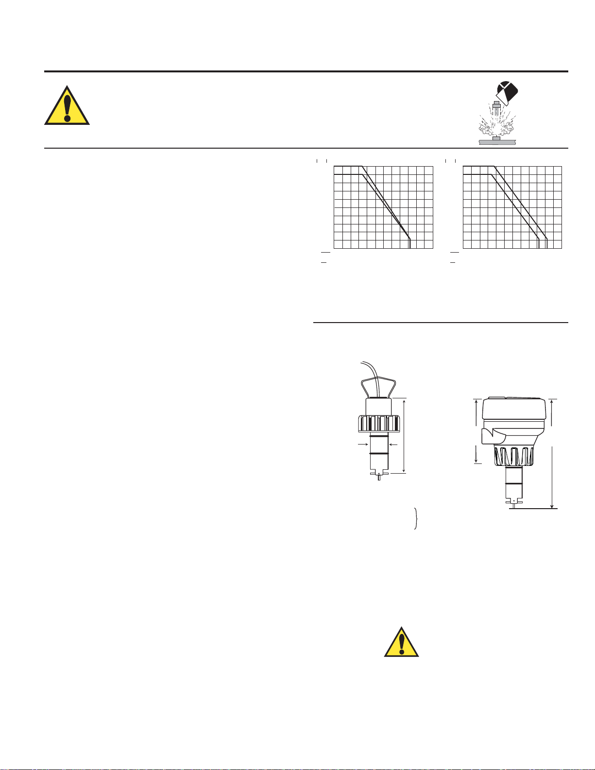
Pressure/Temperature Ratings
Polypropylene Body:
• 12.5 bar (180 psi) max. @ 20 °C (68 °F)
• Self-powered: 1.7 bar (25 psi) max. @ 90 °C (194 °F)
• Low-fl ow: 1.7 bar (25 psi) max. @ 85 °C (185 °F)
Operating Temperature: -18 to 66 °C (0 to 150 °F)
PVDF Body:
• 14 bar (200 psi) max @ 20 °C (68 °F)
• Self-powered: 1.7 bar (25 psi) max @ 100 °C (212 °F)
• Low-fl ow: 1.7 bar (25 psi) max @ 85 °C (185 °F)
Operating Temperature: -18 to 100 °C (0 to 212 °F)
options available
w/o Fluoroloy G® sleeve for rotor pin
Dimensions
Self-Powered Sensor
Low-Flow
Integral Sensor
shown with Transmitter
and Integral Adapter Kit
(sold separately)
WARNING!
The retaining nuts of paddlewheel sensors are not designed for
prolonged contact with aggressive substances. Strong acids,
caustic substances and solvents or their vapor may lead to failure
of the retaining nut, ejection of the sensor and loss of the process
fl uid with possibly serious consequences, such as damage to
equipment and serious personal injury. Retaining nuts that may
have been in contact with such substances, e.g. due to leakage
or spilling, must be replaced.
page 3OMEGA Paddlewheel Flow Sensors
Page 4

2. Location of Fitting
sensor
bale
sensor
cap
tab
black
conduit
cap
notch
black conduit
cap
PROCESS PIPE
(TOP VIEW)
direction of flow
sensor bale
Process
Pipe
+45°
-45°
0°
Recommended sensor upstream/downstream
mounting requirements
2 x 90° Elbow
25x I.D. 5x I.D.
Reducer
15x I.D. 5x I.D.
2 x 90° Elbow
3 dimensions
40x I.D. 5x I.D.
3. Sensor Mounting Position
• Horizontal pipe runs: Mount the sensor in the 45° position for best performance. Mounting in
the 0° position may encounter problems with air bubbles (pipe must be full). Do not mount on
the bottom of the pipe when sediments are present.
• Vertical pipe runs: Mount sensor in any orientation. Upward fl ow is preferred to ensure full pipe.
90° Elbow
20x I.D. 5x I.D.
Pump/Valve
50x I.D. 5x I.D.
4. Standard Sensor Installation
• Lubricate O-rings with a non-petroleum based, viscous
lubricant (grease) compatible with the system.
• Using an alternating/twisting motion, lower the sensor into the
fi tting, making sure the installation arrows on the black cap are
pointing in the direction of fl ow, see Figure A.
• Engage one thread of the sensor cap then turn the sensor until
the alignment tab is seated in the fi tting notch. Hand tighten the
sensor cap. DO NOT use any tools on the sensor cap or the
cap threads and/or fi tting fl ange threads will be damaged, see
Figure B.
5. Sensor Wiring
Technical Notes
• Use 2-conductor shielded cable for cable extensions.
• Cable shield must be maintained through cable splice.
• Refer to your instrument manual for specifi c wiring details.
Low-Flow Sensor Connections to Other Brand Instruments
Other Brands
black
10 kΩ
shield
red
DC sensor power supplied from OMEGA instrument.
10 kΩ Pull-up resistor may be required for non-OMEGA brand instrument.
+
-
Gnd.
Input
3.3 to 24
VDC
Other
instrument
Figure A
Figure B
Self-Powered Sensor Connections to OMEGA Instruments
Black
Frequency (-)
Red
Frequency (+)
Shield
Ground
Low-Flow Sensor Connections to OMEGA Instruments
Black
5 VDC
Red
Frequency in
Shield
Ground
6. Rotor Replacement Procedure
• To remove the rotor, insert a small screwdriver between the rotor and the ear of the sensor.
• Twist the screwdriver blade to fl ex the ear outward enough to remove one end of the rotor and pin.
DO NOT fl ex the ear any more than necessary! If it breaks, the sensor cannot be repaired.
• Install the new rotor by inserting one tip of the pin into the hole, then fl ex the opposite ear back
page 4 OMEGA Paddlewheel Flow Sensors
enough to slip rotor into place.
Page 5

7. K-Factors
A K-Factor is the number of pulses a sensor will generate for each engineering unit of fl uid which passes the sensor. K-factors for
water are listed below in liters and U.S. gallons. For example, in a 1-inch PVC pipe, the self-powered paddlewheel generates 172.07
pulses per gallon of water passing the rotor. K-factors are listed for pipes up to 12 inches. For pipes over 12 inches, consult OMEGA.
PIPE
FITTING
SIZE
(IN.)
SCH 80 PVC TEES FOR SCH 80 PVC PIPE
1/2 FP-5305M 137.42 520.12 271.37 1027.1
3/4 FP-5307M 78.61 297.52 154.08 583.19
1 FP-5310M 45.46 172.07 88.65 335.53
1-1/4 FP-5312M 24.19 91.54 47.24 178.79
1-1/2 FP-5315M 16.44 62.22 32.08 121.42
2 FP-5320M 9.60 36.32 18.87 71.44
2-1/2 PV8T025 5.7683 21.833 11.359 42.994
3 PV8T030 3.5775 13.541 7.0414 26.652
4 PV8T040 2.0147 7.6258 3.9645 15.006
SCH 80 CPVC TEES FOR SCH 80 CPVC PIPE
1/2 FP-5305CM 137.42 520.12 271.37 1027.1
3/4 FP-5307CM 78.61 297.52 154.08 583.19
1 FP-5310CM 45.46 172.07 88.65 335.53
1-1/4 FP-5312CM 24.19 91.54 47.24 178.79
1-1/2 FP-5315CM 16.44 62.22 32.08 121.42
2 FP-5320CM 9.60 36.32 18.87 71.44
SCH 80 PVC SADDLES FOR SCH 80 PVC PIPE
2 FP-5320S 8.5812 32.480 17.633 66.739
2-1/2 FP-5325S 5.7683 21.833 11.359 42.994
3 FP-5330S 3.5775 13.541 7.0414 26.652
4 FP-5340S 2.0147 7.6258 3.9645 15.006
6 FP-5360S 1.0997 4.1623 2.1994 8.3246
8 FP-5380S 0.6263 2.3705 1.3253 5.0164
10 FP-5381S 0.4042 1.5300 0.808 3.0600
12 FP-5382S 0.2801 1.0600 0.571 2.1600
SCH 80 PVC SADDLE ON SCH 40 PVC PIPE
2 FP-5320S 7.2259 27.350 14.452 54.700
2-1/2 FP-5325S 4.9866 18.874 9.8175 37.159
3 FP-5330S 3.3389 12.638 6.2608 23.697
4 FP-5340S 1.7776 6.7282 3.5552 13.456
6 FP-5360S 0.9854 3.7297 1.9708 7.4594
8 FP-5380S 0.5688 2.1527 1.1966 4.5292
10 FP-5381S 0.3567 1.3500 0.740 2.8000
12 FP-5382S 0.2536 0.9600 0.523 1.9800
TYPE
FP-51XX, 53XX
SELF-POWERED
LITERS
U.S.
GAL
FP-56XX
LOW FLOW
LITERS
K-Factors DIN Pipes
TYPE
FP-51XX, 53XX
SELF-POWERED
U.S.
LITERS
GAL
PIPE
FITTING
SIZE
(IN.)
POLYPROPYLENE FITTINGS (DIN/ISO AND BS AND ANSI)
DN 15 FP-5105PO 127.23 481.55 251.75 952.87
DN 20 FP-5107PO 73.207 277.09 148.77 563.10
DN 25 FP-5110PO 37.300 141.18 77.042 291.60
DN 32 FP-5112PO 22.071 83.540 44.709 169.22
DN 40 FP-5115PO 13.544 51.265 27.450 103.90
DN 50 FP-5120PO 7.8193 29.596 16.060 60.789
PVDF FITTINGS (DIN/ISO AND BS AND ANSI)
DN 15 FP-5105 111.19 420.87 218.56 827.26
DN 20 FP-5107 60.277 228.15 129.42 489.87
DN 25 FP-5110 36.116 136.70 74.915 283.55
DN 32 FP-5112 20.950 79.294 41.899 158.59
DN 40 FP-5115 11.490 43.490 22.980 86.980
DN 50 FP-5120 6.8450 25.908 13.312 50.385
LITERS
FP-56XX
LOW FLOW
U.S.
GAL
U.S.
GAL
TYPE
FP-51XX, 53XX
SELF-POWERED
U.S.
LITERS
GAL
PIPE
FITTING
SIZE
(IN.)
CARBON STEEL TEES ON SCH 40 PIPE
1/2 FP-5305CS 97.808 370.20 199.74 756.00
3/4 FP-5307CS 56.027 212.06 115.90 438.69
1 FP-5310CS 37.289 141.14 75.768 286.78
1-1/4 FP-5312CS 16.025 60.655 32.026 121.22
1-1/2 FP-5315CS 11.982 45.350 24.079 91.139
2 FP-5320CS 7.0717 26.767 14.391 54.468
STAINLESS STEEL TEES ON SCH 40 PIPE
1/2 FMG-5305 94.838 358.96 193.98 734.20
3/4 FMG-5307 53.530 202.61 108.88 412.10
1 FMG-5310 33.590 127.14 66.764 252.70
1-1/4 FMG-5312 16.357 61.910 33.849 128.12
1-1/2 FMG-5315 10.676 40.410 20.428 77.320
2 FMG-5320 5.8917 22.300 12.095 45.780
GALVANIZED IRON TEES ON SCH 40 PIPE
1 FP-5310GI 27.619 104.54 56.277 213.01
1-1/4 FP-5312GI 16.639 62.979 33.751 127.75
1 1/2 FP-5315GI 12.335 46.688 24.941 94.401
2 FP-5320GI 7.7832 29.459 15.699 59.420
BRONZE TEES ON SCH 40 PIPE
1 FP-5310BR 27.619 104.54 56.277 213.01
1-1/4 FP-5312BR 16.639 62.979 33.751 127.75
1-1/2 FP-5315BR 12.335 46.688 24.941 94.401
2 FP-5320BR 7.7832 29.459 15.699 59.420
COPPER TEE FITTINGS ON COPPER PIPE SCH K
1/2 FP-5305CU 117.10 443.21 242.50 917.84
3/4 FP-5307CU 56.052 212.16 113.15 428.27
1 FP-5310CU 33.600 127.18 67.749 256.43
1-1/4 FP-5312CU 23.307 88.218 46.615 176.44
1-1/2 FP-5315CU 15.049 56.962 30.565 115.69
2 FP-5320CU 7.7595 29.370 16.746 63.385
COPPER TEE FITTINGS ON COPPER PIPE SCH L
1/2 FP-5305CU 109.49 414.41 226.74 858.22
3/4 FP-5307CU 50.485 191.09 101.91 385.74
1 FP-5310CU 31.662 119.84 63.841 241.64
1-1/4 FP-5312CU 22.576 85.451 45.152 170.90
1-1/2 FP-5315CU 14.573 55.160 29.598 112.03
2 FP-5320CU 7.5575 28.605 16.310 61.74
FP-56XX
LOW FLOW
LITERS
U.S.
GAL
PIPE
FITTING
SIZE
TYPE
(IN.)
STAINLESS STEEL WELDOLETS ON SCH 40 PIPE
2-1/2 FMG-5325 4.9670 18.800 9.9339 37.600
3 FMG-5330 3.2153 12.170 6.4306 24.340
4 FMG-5340 1.8388 6.9600 3.6777 13.920
5 FMG-5350 1.3897 5.2600 2.8692 10.860
6 FMG-5360 0.9749 3.6900 1.9868 7.5200
8 FMG-5380 0.5627 2.1300 1.1466 4.3400
10 FMG-5381 0.3567 1.3500 0.7292 2.7600
12 FMG-5382 0.2536 0.9600 0.5125 1.9400
CARBON STEEL WELDOLETS ON SCH 40 PIPE
2-1/2 FP-5325CS 4.9670 18.800 9.9339 37.600
3 FP-5330CS 3.2153 12.170 6.4306 24.340
4 FP-5340CS 1.8388 6.9600 3.6777 13.920
5 FP-5350CS 1.3897 5.2600 2.8692 10.860
6 FP-5360CS 0.9749 3.6900 1.9868 7.5200
8 FP-5380CS 0.5627 2.1300 1.1466 4.3400
10 FP-5381CS 0.3567 1.3500 0.7292 2.7600
12 FP-5382CS 0.2536 0.9600 0.5125 1.9400
COPPER/BRONZE BRAZOLETS ON SCH 40 PIPE
2-1/2 FP-5325BR 4.9670 18.800 9.934 37.600
3 FP-5330BR 3.2153 12.170 6.431 24.340
4 FP-5340BR 1.8388 6.9600 3.678 13.920
5 FP-5350BR 1.3897 5.2600 2.869 10.860
6 FP-5360BR 0.9749 3.6900 1.987 7.5200
8 FP-5380BR 0.5627 2.1300 1.147 4.3400
10 FP-5381BR 0.3567 1.3500 0.729 2.7600
12 FP-5382BR 0.2536 0.9600 0.513 1.9400
SCH 80 IRON SADDLES ON SCH 80 PIPE
2 FP-5320GIS 8.5495 32.360 17.099 64.720
2-1/2 FP-5325GI 5.8705 22.220 11.223 42.480
3 FP-5330GI 3.5456 13.420 6.980 26.420
4 FP-5340GI 2.0238 7.6600 3.884 14.700
5 FP-5350GI 1.5482 5.8600 3.218 12.180
6 FP-5360GI 1.0806 4.0900 2.230 8.4400
8 FP-5380GI 0.6156 2.3300 1.295 4.9000
10 FP-5381GI 0.4042 1.5300 0.808 3.0600
12 FP-5382GI 0.2801 1.0600 0.571 2.1600
SCH 80 IRON SADDLE ON SCH 40 PIPE
2 FP-5320GIS 7.0859 26.820 14.172 53.640
2-1/2 FP-5325GI 4.9670 18.800 9.934 37.600
3 FP-5330GI 3.1678 11.990 6.135 23.220
4 FP-5340GI 1.8098 6.8500 3.503 13.260
5 FP-5350GI 1.4082 5.3300 2.917 11.040
6 FP-5360GI 0.9934 3.7600 1.913 7.2400
8 FP-5380GI 0.5627 2.1300 1.162 4.4000
10 FP-5381GI 0.3567 1.3500 0.740 2.8000
12 FP-5382GI 0.2536 0.9600 0.523 1.9800
FP-51XX, 53XX
SELF-POWERED
LITERS
U.S.
GAL
FP-56XX
LOW FLOW
LITERS
U.S.
GAL
8. H-Dimensions
The plastic sensor insert in the Weldolet fi tting MUST be
removed during the welding process. When reinstalled, it
is important that the insert be threaded to the proper height
("H" dimension).
"H"
Carbon Steel
Part Number
Stainless Steel
Part Number
Copper/Bronze
Part Number
“H” dimension
mm inches
FP-5325CS FMG-5325 FP-5325BR 60.45 2.38
FP-5330CS FMG-5330 FP-5330BR 59.18 2.33
FP-5340CS FMG-5340 FP-5340BR 58.92 2.32
FP-5350CS FMG-5350 FP-5350BR 58.42 2.30
FP-5360CS FMG-5360 FP-5360BR 78.48 3.09
FP-5360CS FMG-5360 FP-5360BR 75.18 2.96
FP-5380CS FMG-5380 FP-5380BR 69.34 2.73
FP-5381CS FMG-5381 FP-5381BR 139.19 5.48
FP-5382CS FMG-5382 FP-5382BR 133.35 5.25
page 5OMEGA Paddlewheel Flow Sensors
Page 6

9. OMEGA Fittings
Type Description
2 to 4 inch, cut 1-7/16 inch hole in pipe
Over 4 inch, cut 2-1/8 inch hole in pipe
Special order 14 in. to 36 in.
0.5 to 2 inch versions
MPVC or CPVC
2 to 4 inch, cut 1-7/16 inch hole in pipe
6 to 8 inch, cut 2-1/8 inch hole in pipe
Available in 10 and 12 inch sizes only
Cut 2-1/2 inch hole in pipe
Weld in place using solvent cement
Iron, Carbon Steel,
316 SS Threaded
tees
Carbon steel &
stainless steel
Weld-on
Weldolets
2 to 4 inch, cut 1-7/16 inch hole in pipe
Over 4 inch, cut 2-1/8 inch hole in pipe
For pipes from DN 15 to 50 mm
PP or PVDF
Type Description
Plastic
tees
Metric
Union
Fitting
PVC
Saddles
Iron
Strap-on
saddles
PVC
Glue-on
Saddles
1.5 in. to 2 in. PVDF insert
Fiberglass
tees
FPT
0.5 to 2 in. versions
Mounts on threaded pipe ends
10. Ordering Information
Self-Powered
Part No.
Low-Flow
Part No.
Description
FP-5300 FP-5600 Sensor, Polypropylene, Titanium Rotor Pin, PVDF Rotor (black), 1/2 to 4 Inch Pipe
FP-5301 FP-5601 Sensor, Polypropylene, Titanium Rotor Pin, PVDF Rotor (black), 5 to 8 Inch Pipe
FP-5302 FP-5602 Sensor, Polypropylene, Titanium Rotor Pin, PVDF Rotor (black) 10 to 36 Inch Pipe
FP-5100 FP-5603 Sensor, PVDF (natural), Hastelloy-C Rotor Pin, PVDF Rotor (natural),
1
/2 to 4 Inch Pipe
FP-5101 FP-5604 Sensor, PVDF (natural), Hastelloy-C Rotor Pin, PVDF Rotor (natural), 5 to 8 Inch Pipe
FP-5102 N/A Sensor, PVDF (natural), Hastelloy-C Rotor Pin, PVDF Rotor (natural), 10 to to 36 Inch Pipe
FP-5100-AP N/A Sensor, PVDF (natural), PVDF (natural) Rotor Pin, PVDF Rotor (natural),
1
/2 to 4 Inch Pipe
FP-5101-AP N/A Sensor, PVDF (natural), PVDF (natural) Rotor Pin, PVDF Rotor (natural), 5 to to 8 Inch Pipe
FP-8501 FP-8501A Sensor, Integral, Polypropylene, Titanium Rotor Pin, PVDF Rotor (black), 1/2 to 4 Inch Pipe
FP-8502 FP-8502A Sensor, Integral, Polypropylene, Titanium Rotor Pin, PVDF Rotor (black), 5 to 8 Inch Pipe
FP-8503-AP FP-8503A-AP Sensor, Integral, PVDF (natural), Hastelloy-C Rotor Pin, PVDF Rotor (natural), 1/2 to 4 In. Pipe
FP-8503 FP8503A Sensor, Integral, PVDF (natural), PVDF (natural) Rotor Pin, PVDF Rotor (natural), 1/2 to 4 In. Pipe
FMK-515-3P3 FMK-2536-3P3 Sensor, Wet-Tap, Polypropylene, Titanium Rotor Pin, PVDF Rotor (black), 1/2 to 4 Inch Pipe
FMK-515-3P5 FMK-2536-3P5 Sensor, Wet-Tap, Polypropylene, Titanium Rotor Pin, PVDF Rotor (black), 10 to 36 Inch Pipe
FP-319 FP-319 Wet-Tap Valve Assembly (Use with Wet-Tap sensors only)
Accessories
FMK-1538-2 FMK-2536-1 Rotor, PVDF Black
FMK-51545-1 FMK-2536-5 Rotor and Pin, PVDF Natural
FMK-1546-1 FMK-1546-1 Rotor Pin, Titanium
FMK-1546-2 FMK-1546-2 Rotor Pin, Hastelloy-C
FMK-1546-3 FMK-1546-3 Rotor Pin, Tantalum
FMK-1546-4 FMK-1546-4 Rotor Pin, Ceramic
FPP-1220-0021 FPP-1220-0021 O-Ring, FPM-FKM
FPP-1224-0021 FPP-1224-0021 O-Ring, EPDM
FPP-1228-0021 FPP-1228-0021 O-Ring, FFKM-Perfl uoroelastomer
FMK-31536-1 FMK-31536-1 Sensor Plug, Polypro
PH-31542-TC N/A Sensor Cap, Red (Use with the FP-8501, 8502, 8503-AP)
N/A FMK-2536-9 Sensor Cap, Blue (Use with the FP-8501A, 8502A, 8503A -AP)
FMK-31934 FMK-31934 Conduit Cap
FP-90-IM FP-90-IM Integral Mounting Kit
Chemical Compatibility
OMEGA products are manufactured in a variety of wetted materials to suit various liquids and chemicals.
All plastic materials including typical piping types (PVC, PVDF, PP and PE) are more or less permeable to contained media, such as water or volatile
substances, including some acids. This effect is not related to porosity, but purely a matter of gas diffusion through the plastic. If the plastic material is
compatible with the medium according to the application guidelines, the permeation will not damage the plastic itself. However, if the plastic encloses
other sensitive components, as is the case with OMEGA plastic paddlewheel sensors, these components may be affected or damaged by the media
diffusing through the plastic body and rotor.
PVDF paddlewheel sensor failure when used in hot nitric acid applications has been reported. PVDF is known to allow for substantial permeation of
nitric acid constituents without being damaged itself. No clear guideline can be given here, since the damaging effect to the sensor is highly dependent
on temperature, pressure and concentration. Utilizing sensors in applications with aggressive substances is possible. On special request OMEGA can
provide sensors with a different internal resin encapsulation (potting) that will delay the damaging effect of acids to the sensors. For all Special Product
inquiries or to place an order, please contact OMEGA.
page 6 OMEGA Paddlewheel Flow Sensors
Page 7

USASA
MAD E
IN
IN
WARRANTY/DISCLAIMER
OMEGA ENGINEERING, INC. warrants this unit to be free of defects in materials and workmanship for a period
of 13 months from date of purchase. OMEGA’s WARRANTY adds an additional one (1) month grace period to the
normal one (1) year product warranty to cover handling and shipping time. This ensures that OMEGA’s customers
receive maximum coverage on each product.
If the unit malfunctions, it must be returned to the factory for evaluation. OMEGA’s Customer Service Department
will issue an Authorized Return (AR) number immediately upon phone or written request. Upon examination by
OMEGA, if the unit is found to be defective, it will be repaired or replaced at no charge. OMEGA’s WARRANTY
does not apply to defects resulting from any action of the purchaser, including but not limited to mishandling,
improper interfacing, operation outside of design limits, improper repair, or unauthorized modification. This
WARRANTY is VOID if the unit shows evidence of having been tampered with or shows evidence of having
been damaged as a result of excessive corrosion; or current, heat, moisture or vibration; improper specifi cation;
misapplication; misuse or other operating conditions outside of OMEGA’s control. Components which wear are not
warranted, including but not limited to contact points, fuses, and triacs.
OMEGA is pleased to offer suggestions on the use of its various products. However, OMEGA neither assumes
responsibility for any omissions or errors nor assumes liability for any damages that result from the use of its
products in accordance with information provided by OMEGA, either verbal or written. OMEGA warrants only that
the parts manufactured by it will be as specifi ed and free of defects. OMEGA MAKES NO OTHER WARRANTIES
OR REPRESENTATIONS OF ANY KIND WHATSOEVER, EXPRESS OR IMPLIED, EXCEPT THAT OF TITLE,
AND ALL IMPLIED WARRANTIES INCLUDING ANY WARRANTY OF MERCHANTABILITY AND FITNESS FOR A
PARTICULAR PURPOSE ARE HEREBY DISCLAIMED.
LIMITATION OF LIABILITY: The remedies of purchaser set forth herein are exclusive, and the total liability of
OMEGA with respect to this order, whether based on contract, warranty, negligence, indemnifi cation, strict liability
or otherwise, shall not exceed the purchase price of the component upon which liability is based. In no event shall
OMEGA be liable for consequential, incidental or special damages.
CONDITIONS: Equipment sold by OMEGA is not intended to be used, nor shall it be used: (1) as a “Basic Component”
under 10 CFR 21 (NRC), used in or with any nuclear installation or activity; or (2) in medical applications or used on
humans. Should any Product(s) be used in or with any nuclear installation or activity, medical application, used on
humans, or misused in any way, OMEGA assumes no responsibility as set forth in our basic WARRANTY/DISCLAIMER
language, and, additionally, purchaser will indemnify OMEGA and hold OMEGA harmless from any liability or damage
whatsoever arising out of the use of the Product(s) in such a manner.
RETURN REQUESTS/INQUIRIES
Direct all warranty and repair requests/inquiries to the OMEGA Customer Service Department. BEFORE RETURNING
ANY PRODUCT(S) TO OMEGA, PURCHASER MUST OBTAIN AN AUTHORIZED RETURN (AR) NUMBER FROM
OMEGA’S CUSTOMER SERVICE DEPARTMENT (IN ORDER TO AVOID PROCESSING DELAYS). The assigned AR
number should then be marked on the outside of the return package and on any correspondence.
The purchaser is responsible for shipping charges, freight, insurance and proper packaging to prevent breakage in transit.
FOR WARRANTY RETURNS, please have the following
information available BEFORE contacting OMEGA:
1. Purchase Order number under which the product was
PURCHASED,
2. Model and serial number of the product under
warranty, and
3. Repair instructions and/or specifi c problems relative to
the product.
FOR NON-WARRANTY REPAIRS,
current repair charges. Have the following information
available BEFORE contacting OMEGA:
1. Purchase Order number to cover the COST of the
repair,
2. Model and serial number of the product, and
3. Repair instructions and/or specifi c problems relative to
the product.
consult OMEGA for
OMEGA’s policy is to make running changes, not model changes, whenever an improvement is possible. This affords our customers
the latest in technology and engineering.
OMEGA is a registered trademark of OMEGA ENGINEERING, INC.
© Copyright 2011 OMEGA ENGINEERING, INC. All rights reserved. This document may not be copied, photocopied, reproduced,
translated, or reduced to any electronic medium or machine-readable form, in whole or in part, without the prior written consent of
OMEGA ENGINEERING, INC.
page 7OMEGA Paddlewheel Flow Sensors
Page 8

Where Do I Find Everything I Need for
Process Measurement and Control?
OMEGA…Of Course!
Shop online at www.omega.com
TEMPERATURE
•
Thermocouple, RTD & Thermistor Probes, Connectors, Panels & Assemblies
•
Wire: Thermocouple, RTD & Thermistor
•
Calibrators & Ice Point References
•
Recorders, Controllers & Process Monitors
•
Infrared Pyrometers
PRESSURE, STRAIN AND FORCE
•
Transducers & Strain Gages
•
Load Cells & Pressure Gages
•
Displacement Transducers
•
Instrumentation & Accessories
FLOW/LEVEL
•
Rotameters, Gas Mass Flowmeters & Flow Computers
•
Air Velocity Indicators
•
Turbine/Paddlewheel Systems
•
Totalizers & Batch Controllers
pH/CONDUCTIVITY
•
pH Electrodes, Testers & Accessories
•
Benchtop/Laboratory Meters
•
Controllers, Calibrators, Simulators & Pumps
•
Industrial pH & Conductivity Equipment
DATA ACQUISITION
•
Data Acquisition & Engineering Software
•
Communications-Based Acquisition Systems
•
Plug-in Cards for Apple, IBM & Compatibles
•
Datalogging Systems
•
Recorders, Printers & Plotters
HEATERS
•
Heating Cable
•
Cartridge & Strip Heaters
•
Immersion & Band Heaters
•
Flexible Heaters
•
Laboratory Heaters
ENVIRONMENTAL
MONITORING AND CONTROL
•
Metering & Control Instrumentation
•
Refractometers
•
Pumps & Tubing
•
Air, Soil & Water Monitors
•
Industrial Water & Wastewater Treatment
•
pH, Conductivity & Dissolved Oxygen Instruments
6-0515.090-OM/(E-3/12) M-3814/0312
 Loading...