

Page 1
User’s Guide
omega.com
®
®
omega.com
http://www.omega.com
e-mail: info@omega.com
®
FLSC790-MA
4-20 mA Module
Page 2

omega.com
omega.com
OMEGAnet® On-Line Service Internet e-mail
http://www.omega.com info@omega.com
Servicing North America:
USA: One Omega Drive, Box 4047
ISO 9001 Certified Stamford, CT 06907-0047
Canada: 976 Bergar
Tel: (203) 359-1660 FAX: (203) 359-7700
e-mail: info@omega.com
Laval (Quebec) H7L 5A1
Tel: (514) 856-6928 FAX: (514) 856-6886
e-mail: info@omega.ca
®
®
®
For immediate technical or application assistance:
USA and Canada: Sales Service: 1-800-826-6342 / 1-800-TC-OMEGA
Customer Service: 1-800-622-2378 / 1-800-622-BEST
Engineering Service: 1-800-872-9436 / 1-800-USA-WHEN
TELEX: 996404 EASYLINK: 62968934 CABLE: OMEGA
SM
SM
SM
Mexico and Tel: (001) 800-826-6342 FAX: (001) 203-359-7807
Latin America: En Español: (001) 203-359-7803 e-mail: espanol@omega.com
Servicing Europe:
Benelux: Postbus 8034, 1180 LA Amstelveen, The Netherlands
Tel: (31) 20 6418405 FAX: (31) 20 6434643
Toll Free in Benelux: 0800 0993344
e-mail: nl@omega.com
Czech Republic: ul. Rude armady 1868, 733 01 Karvina-Hranice
Tel: 420 (69) 6311899 FAX: 420 (69) 6311114
Toll Free: 0800-1-66342 e-mail: czech@omega.com
France: 9, rue Denis Papin, 78190 Trappes
Tel: (33) 130-621-400 FAX: (33) 130-699-120
Toll Free in France: 0800-4-06342
e-mail: france@omega.com
Germany/Austria: Daimlerstrasse 26, D-75392 Deckenpfronn, Germany
Tel: 49 (07056) 3017 FAX: 49 (07056) 8540
Toll Free in Germany: 0130 11 21 66
e-mail: info@omega.de
United Kingdom: One Omega Drive, River Bend Technology Centre
ISO 9002 Certified Northbank, Irlam, Manchester
M44 5EX, United Kingdom
Tel: 44 (0161) 777-6611 FAX: 44 (0161) 777-6622
Toll Free in United Kingdom: 0800-488-488
e-mail: info@omega.co.uk
It is the policy of OMEGA to comply with all worldwide safety and EMC/EMI regulations that apply. OMEGA
is constantly pursuing certification of its products to the European New Approach Directives. OMEGA will add
the CE mark to every appropriate device upon certification.
The information contained in this document is believed to be correct, but OMEGA Engineering, Inc. accepts no liability for any
errors it contains, and reserves the right to alter specifications without notice.
WARNING: These products are not designed for use in, and should not be used for, patient-connected applications.
Page 3
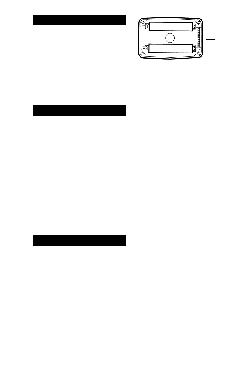
TABLE OF CONTENTS
Introduction ................................................1
Installation.................................................. 1
Wiring......................................................... 2
Calibration.................................................. 4
Dimensions.................................................5
Specifications .............................................6
Parts List .................................................... 7
Troubleshooting .........................................7
Warranty/Disclaimer .................................. 9
Return Requests/Inquiries .......................... 9
INTRODUCTION
Caution: This 4-20 mA Module is not FM
Approved. Therefore , use of this module with an approved metering system,
voids FM Approval.
NOTE: This module requires an input power
supply of 7 to 30 volts DC. (24 VDC is
recommended) The DC signal will power
the meter electronics, leaving the batteries as backup for the meter electronics.
NOTE: Field Calibration is required.
This manual is designed to be used only with
FTB790 Series Turbine Meters. More specifically, turbine housings with the following models: FTB791, FTB792, FTB793,
FTB794, and FTB795.
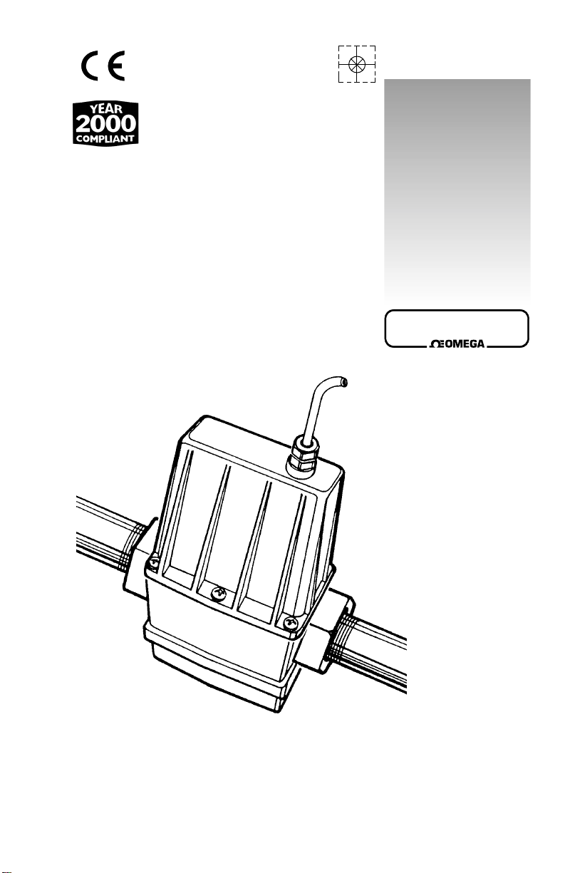
INSTALLATION
T o install this module, follow the instructions
given below.
1. Remove the back coverplate from the
turbine housing.
2. Remove the display electronics from the
front of the turbine.
NOTE: If you are installing more than one
module at a time, take care to keep the
proper electronics paired with the original turbine.
3. The 4-20 mA Module connects to a 10pin connector located on the back side
of the computer electronics next to the
negative battery connectors. The 10-pin
connector is sealed with a clear plastic
+–
J2
J6
+–
sealant that must be carefully pried out
with a small sharp tool inserted gently
at the edges.
4. Remove the backing from the double-sided
tape on the module’s circuit assembly.
5. Carefully align the top pin on the circuit
assembly with the J2 position on the 10pin connector and gently press the
module’s circuit assembly into position
between the batteries. The bottom pin
will align with the J6 position.
6. Guide the loose ends of the wires from the
circuit assembly through the housing’s ca vity to the back side of the turbine.
7. Install the display electronics to the front
side of the turbine and tighten the four
screws snugly.
8. Connect the loose ends of the wires from
the electronics circuit assembly to the
terminal block marked “From EDM.”
Connect wires per colors noted beside
connection pins.
NOTE: Ten feet of wire is provided with the
module. If trimming is necessary, do it no w.
If you provide your own wire, prepare it
for connection prior to the next step.
9. Connect the wires at the module’s terminal block marked “Cable from Customer” as illustrated in Wiring Section.
10. Complete connections to the interface
device according to the manufacturer’s
instructions.
11. Before installing the module onto the turbine housing, adjust the ZERO and SPAN
trimpots as noted in Calibration Section.
When adjustments are finished, make sure
the O-ring is fully seated and no wires are
pinched. Then, secure the module onto the
housing by snugly tightening the six screws
provided with the module.
1
Page 4
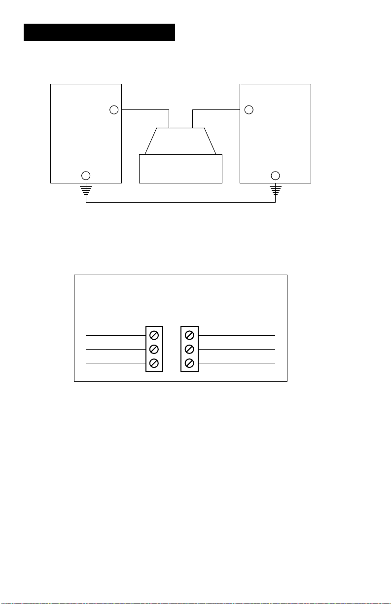
WIRING
This is the wiring diagram for the 4-20 mA output.
7-30 VDC
Power Supply
Red
White
Black
I + I –
White Black
+–
4-20 mA
Meter
Output (4-20 mA)
4-20 mA Module Terminal Connections
Wires
from
EDM
Cable from
Customer
Equipment
Not Used (Red)
I (–) Loop (Black)
I (+) Loop (White)
Customer’s
Recording Device
++
––
Wires from EDM detail:
White wire from 10-pin connector J2.
Red wire from 10-pin connector J5.
Black wire from 10-pin connector J6.
2
Page 5

WIRING
This is the wiring diagram for the 0-5 V output.
7-30 VDC
Power Supply
Red
White
Black
Red
+
White Black
Meter
Secondary Output (0-5 Volt) (1-4 VDC)
0-5 Volt Terminal Connections
Wires
from
EDM
Cable from
Customer
Equipment
Out (+) Signal (Red)
(–) Common Ground (Black)
(+) +7 to +30 Volts (White)
Customer’s
Recording Device
+
––
Wires from EDM detail:
White wire from 10-pin connector J2.
Red wire from 10-pin connector J5.
Black wire from 10-pin connector J6.
3
Page 6

CALIBRATION
Adjusting ZERO and SPAN
The following adjustments apply to both the
4-20 mA and 0-5 V outputs. T he factory recommends when using 0-5 V signal, do not
go below 1 V or above 4 V as output signal
in the linear range.
Before initial adjustments, set both trimpots
to their maximum position by turning each
control clockwise twenty (20) turns. The
control’s internal clutch will click quietly at
the end position.
To adjust Zero reading, start fluid flow at its
lowest anticipated flowrate within the linear
flow range of the turbine. Then turn the
ZERO trimpot counterclockwise until the
indicated reading begins to rise from 4 mA
(or 1 V). Then turn back to the 4 mA (or 1 V)
reading. This is the true ZERO read. Any
flowrate below this “threshold,” including no
flow, will produce a 4 mA (or 1 V) reading.
To adjust SPAN, start the fluid flow to its
highest anticipated flowrate within the linear flow range of the turbine. Then, turn the
SP AN trimpot counter clockwise until the indicator just drops to 20 mA (or 4 V). Any
flowrate above this will produce an indication higher than 20 mA (or 4 V).
Usually, no further adjustment will be required. Howe ver, if “fine tuning” is required,
note that adjustments in ZERO trimpot will
require adjustments in SPAN. the converse
is not true, adjusting the SPAN setting will
have little or no effect on the ZERO setting.
4
Page 7

DIMENSIONS
➤
3.0 in.
(7.6 cm)
➤
0.3 in. (0.8 cm)
➤
1.2 in.
(3.1 cm)
2.8 in.
(7.1 cm)
➤
➤
3.3 in.
(8.4 cm)
➤
2.0 in.
(5.1 cm)
➤➤
5
Page 8

SPECIFICATIONS
Mechanical
Housing Material: Nylon 6/6
Strain Relief: Hubble PG7. Grip range 0.11-0.26
Strain Relief Thread: Female 1/2-20 UNF-2B
Cable: Belden 9363 (22AWG-2 conductor w/drain wire and shield)
Cable Length: 10 ft. (3m) provided
Operation Temperature: 0° to +150°F (–17° to 65°C)
Storage Temperature: –40° to +180°F (–40° to +82°C)
Power
Type: Loop powered
Burden (Minimum): 7 VDC
Maximum: 30 VDC
Isolated: No
Primary Output (4-20 mA)
Type: Loop
Minimum: 4 mA
Maximum: 25 mA
Output (0-5 Volt)
Type: Voltage Mode
Minimum: 1 Volt
Maximum: 4 Volts
Input
Open Collector from FTB790 Series Electronics or Conditioned Signal Module.
4-20 mA Module will accept frequencies generated only by FTB790 Series turbine
housings. This module should not be used with frequency generating devices other
than FTB790 Series Models.
6
Page 9

PARTS LIST
Part Number Description Qty.
901002-52 O-ring............................................................................................ 1
125501-1 Circuit Assembly Kit (10 pin connector)..................................... 1
904005-27 Screws........................................................................................... 6
Call OMEGA Sales Department and reference base part number (FLSC790-MA) to order
spare parts.
TROUBLESHOOTING
Symptom Probable Cause Corrective Action
No output signal 1. Incorrect or no input power Supply correct power requirements.
2. Not wired correctly Check owner’ s manual for correct installation.
3. Broken connection Check resistance to determine location of
4. Defective PC board connector Contact distributor or factory for replacement.
5. Defective unit Contact distributor or factory for replacement.
Signal does rise 1. Zero trimpot not set correctly Reinitiate Zero & Span adjustments - careful
above 4 mA to increase Zero read above 4 and then turn
2. No signal from meter See Turbine and Display Electronics owner’s
break.
back to 4 mA reading to avoid false 4 mA
signal.
manual.
7
Page 10

NOTES
8
Page 11

MADE
IN
USA
WARRANTY / DISCLAIMER
OMEGA ENGINEERING, INC. warrants this unit to be free of defects in materials and workmanship for a
period of 13 months from date of purchase. OMEGA W arranty adds an additional one (1) month grace per iod
to the normal one (1) year product warranty to cover handling and shipping time . This ensures that OMEGA’s
customers receive maximum coverage on each product.
If the unit malfunctions, it must be returned to the factory for evaluation. OMEGA’s Customer Service Department will issue an Authorized Return (AR) number immediately upon phone or written request. Upon
examination by OMEGA, if the unit is found to be defective, it will be repaired or replaced at no charge.
OMEGA’s WARRANTY does not apply to defects resulting from any action of the purchaser, including but
not limited to mishandling, improper interfacing, operation outside of design limits, improper repair, or unauthorized modification. This WARRANTY is VOID if the unit shows evidence of having been tampered
with or shows evidence of having been damaged as a result of excessive corrosion; or current, heat, moisture
or vibration; improper specification; misapplication; misuse or other operating conditions outside of OMEGA’s
control. Components which wear are not warranted, including but not limited to contact points, fuses, and triacs.
OMEGA is pleased to offer suggestions on the use of its various products. However, OMEGA neither
assumes responsibility for any omissions or errors not assumes liability for any damages that result
from the use of its products in accordance with information provided by OMEGA, either verbal or
written. OMEGA warrants only that the parts manufactured by it will be as specified and free of
defects. OMEGA MAKES NO OTHER WARRANTIES OR REPRESENTATIONS OF ANY KIND
WHATSOEVER, EXPRESS OR IMPLIED, EXCEPT THAT OF TITLE, AND ALL IMPLIED WARRANTIES INCLUDING ANY WARRANTY OF MERCHANTABILITY AND FITNESS FOR A PARTICULAR PURPOSE ARE HEREBY DISCLAIMED. LIMITATION OF LIABILITY: The remedies
of purchaser set forth herein are e xclusiv e, and the total liability of OMEGA with respect to this order,
whether based on contract, warranty, negligence, indemnification, strict liability or otherwise, shall
not exceed the purchase price of the component upon which liability is based. In no event shall OMEGA
be liable for consequential, incidental or special damages.
CONDITIONS: Equipment sold by OMEGA is not intended to be used, nor shall it be used: (1) as a “Basic
Component” under 10 CFR 21 (NRC), used in or with any nuclear installation or activity; or (2) in medical applications or used on humans. Should any Product(s) be used in or with any nuclear installation or acti vity, medical
application, used on humans, or misused in any way, OMEGA assumes no r esponsibility as set forth in our basic
W ARRANTY/DISCLAIMER language, and, additionall y, purchaser will indemnify OMEGA and hold OMEGA
harmless from any liability or damage whatsoever arising out of the use of the Product(s) in such a manner.
RETURN REQUESTS / INQUIRIES
Direct all warranty and repair requests/inquiries to the OMEGA Customer Service Department. BEFORE
RETURNING ANY PRODUCT(S) TO OMEGA, PURCHASER MUST OBTAIN AN AUTHORIZED RETURN (AR) NUMBER FROM OMEGA’S CUSTOMER SERVICE DEPARTMENT (IN ORDER TO AVOID
PROCESSING DELAYS). The assigned AR number should then be marked on the outside of the return
package and on any correspondence. The purchaser is responsible for shipping charges, freight, insurance
and proper packaging to prevent breakage in transit.
FOR WARRANTY RETURNS, please have the
following information available BEFORE contacting OMEGA:
1. Purchase Order number under which the product was PURCHASED,
2. Model and serial number of the product under
warranty, and
3. Repair instructions and/or specific problems
relative to the product.
OMEGA’s policy is to make running changes, not model changes, whenever an improvement is possible. This affords our
customers the latest in technology and engineering.
OMEGA is a registered trademark of OMEGA ENGINEERING, INC.
© Copyright 1998 OMEGA ENGINEERING, INC. All rights reserved. This document may not be copied, photocopied,
reproduced, translated, or reduced to any electronic medium or machine-readable form, in whole or in part, without the
prior written consent of OMEGA ENGINEERING, INC.
FOR NON-WARRANTY RETURNS, consult
OMEGA for current repair charges. Have the following information available BEFORE contacting
OMEGA:
1. Purchase Order number to cover the COST of
the repair,
2. Model and serial number of the product, and
3. Repair instructions and/or specific problems
relative to the product.
9
Page 12

Where Do I Find Everything I Need for
Process Measurement and Control?
OMEGA… Of Course!
TEMPERATURE
✓
Thermocouple, RTD & Thermistor Probes, Connectors, Panels & Assemblies
✓
Wire: Thermocouple, RTD & Thermistor
✓
Calibrators & Ice Point References
✓
Recorders, Controllers & Process Monitors
✓
Infrared Pyrometers
PRESSURE, STRAIN AND FORCE
✓
Transducers & Strain Gauges
✓
Load Cells & Pressure Gauges
✓
Displacement Transducers
✓
Instrumentation & Accessories
FLOW/LEVEL
✓
Rotameters, Gas Mass Flowmeters & Flow Computers
✓
Air Velocity Indicators
✓
Turbine/Paddlewheel Systems
✓
Totalizers & Batch Controllers
pH/CONDUCTIVITY
✓
pH Electrodes, Testers & Accessories
✓
Benchtop/Laboratory Meters
✓
Controllers, Calibrators, Simulators & Pumps
✓
Industrial pH & Conductivity Equipment
DATA ACQUISITION
✓
Data Acquisition & Engineering Software
✓
Communications-Based Acquisition Systems
✓
Plug-in Cards for Apple, IBM & Compatibles
✓
Datalogging Systems
✓
Recorders, Printers & Plotters
HEATERS
✓
Heating Cable
✓
Cartridge & Strip Heaters
✓
Immersion & Band Heaters
✓
Flexible Heaters
✓
Laboratory Heaters
ENVIRONMENTAL
MONITORING AND CONTROL
✓
Metering & Control Instrumentation
✓
Refractometers
✓
Pumps & Tubing
✓
Air, Soil & Water Monitors
✓
Industrial Water & Wastewater Treatment
✓
pH, Conductivity & Dissolved Oxygen Instruments
M3217 11/98
 Loading...