

Page 1

FLSC-62A Wire Loop Powered 4-20mA Transmitter
SPECIFICATIONS
Temperature:
Input Voltage:
Signal Input:
Analog Output
Features:
Enclosure:
Operating -40 to 85°C
Storage -65 to 125°C
Minimum = 7 V + (20mA X RL)
Maximum = 28 V + (4mA X RL)
Protected against polarity reversal
Frequency 0-10 KHz
Amplitude 50 mV – 35 V sine or square wave
Sensitivity field adjustable
Impedance 50K
4mA @ 0 Hz, 20mA @ desired full scale frequency
Full scale range -- 100 Hz-10 KHz selectable
Response time -- 95% of change in 1 second
Linearity -- .3% F/S
Tempco -- < 2% of reading over entire temperature range
Mounts directly on flowmeter
FM Approved, CSA Certified
Class I Groups B, C, D
Class II Groups E, F, G
Weight 1.7 lbs.
The FLSC-62A is a 2-wire loop powered analog transmitter designed to linearly convert a
frequency input to an equivalent 4-20mA current output. When it incorporates with a turbine
flowmeter a current representation proportional to flow is obtainable. Data transmission in a
current format exhibits excellent noise immunity and the capability of long distance
transmission.
A full-scale frequency range of 100 Hz-10 KHz is selectable, via S1. The span adjustment
establishes the frequency point at which a 20mA output is achieved. The sensitivity adjustment
permits the FLSC-62A to discriminate between a signal input and noise by increasing (CCW) or
decreasing (CW) the input signal amplitude necessary to process a valid signal. ‘Test’ S2 when
depressed, illuminates D1 if loop voltage and input signal both are present.
Installation of the FLSC-62A requires only 2 wires because it is a true 2-wire transmitter: input
power and signal output utilizes the same wires.
Rev. C Update 2/02
Page 2
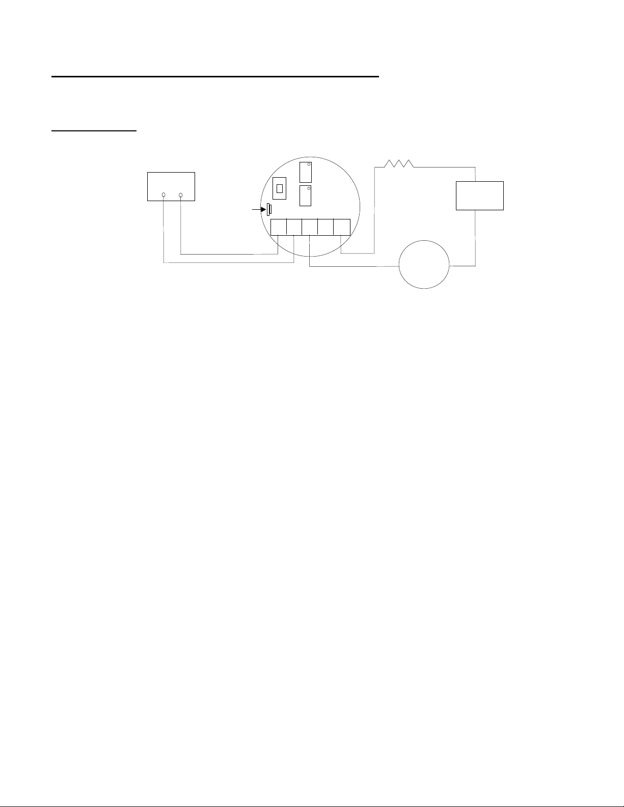
BENCH TEST CALIBRATION PROCEDURE
0
Required Equipment: Power Supply 12-28v, Digital Multimeter (DMM), Frequency Generator, &
Frequency Counter
Test Procedure:
250 Ω
Z
0 = 100-1000Hz
Frequency
Gen/Ctr
- +
Connect DMM positive lead to power supply positive, connect DMM negative lead to J1-3,
A)
1 = 1 KHz-10KHz
SENSITIVITY
R1
set DMM function to mA DC
B)
Connect power supply negative lead to 250 Ω resistor, connect other resistor leg to J1-5
Connect frequency generator positive & negative leads to J1-1,2; respectively. Set output
C)
to sinewave & amplitude to zero
Set S1 for desired fr equency range
D)
Turn power supply & frequency generator ‘O N’, DMM should indicate approximately
E)
4.00mA
Adjust ‘ZERO’ (R25) for 4. 00m A DMM indication (record data)
F)
Set ‘Sensitivity’ adjust (R1) fully clockwise
G)
Adjust signal amplitude of frequency generator to 50m v & frequency to maximum desired
H)
point (full scale frequency) (record data)
Adjust ‘SPAN’ (R19) for 20.00m A DMM indication (record dat a)
I)
Reduce signal amplitude of frequency generator to zero, adjust ‘ZERO’ (R25) for 4.00mA
J)
DMM indication if necessary
Adjust signal amplitude of frequency generator to 50m v, adjust ‘SPAN’ (R19) for 20.00mA
K)
DMM indication if necessary
Adjust frequency of frequency generator to exactly 50% of maximum frequency point in
L)
step H, DMM should indicate 12.00mA ± .06. Repeat for 25% & 75% full scale
frequencies(record data)
E
S1
R
O
1
S
P
FLSC-62A
A
N
54321
DMM
mA
- +
-
Power
Supply
12-28 VDC
+
~
DC
To check linearity @ any frequency point, incor por ate the following formula:
(F/F
X 16) + 4 = mA
max
(Where F = Flowrate frequency in Hz)
(F
= Frequency in Hz at which 20mA is set)
max
Ex. Assume maximum frequency point = 2000 Hz (20.00mA) Check for linearity @ 750
Hz point
750/2000 = .375
16 X .375 = 6
6 + 4 = 10; DMM should indicate 10.00mA @ 750 Hz input
Rev. C Update 2/02
Page 3

TYPICAL LOOP CONFIGURATIONS
-
+
J1-3
FLSC-62A
J1-5
J1-3
FLSC-62A
J1-5
+
+
RSENSE
-
+
-
+
J1-3
FLSC-62A
J1-5
J1-3
+
RLOAD
-
+
12-28 VDC
+
POWER
SUPPLY
12-28 VDC
+
POWER
-
-
SUPPLY
FLSC-62A
-
-
RSENSE
J1-5
-
RLOAD
-
+
Rev. C Update 2/02
Page 4

Page 5

File:\Elect\FLSC-62A.dwg
FLSC-62A 4-20mA Transmitter
FLSC-62A-01
Rev. C Update 2/02
 Loading...