

Page 1
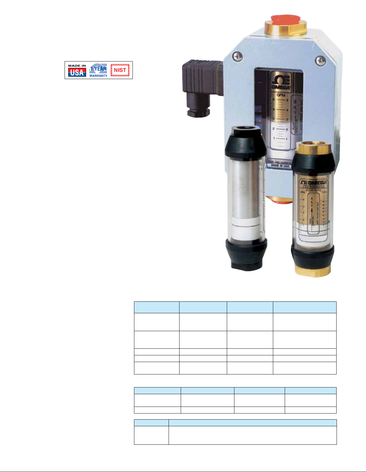
ECONOMICAL IN-LINE LIQUID
FLOWMETERS
FLMW and FLMH Series
†
Optional
U Direct-Reading
Dual Scales
U Ranges from
0.05 to 150 GPM
U High Pressure: 3500 psi
(Brass or Aluminum);
6000 psi (Stainless Steel)
U High Temperature:
116°C (240°F) Standard,
204 or 316°C
(400 or 600°F) Optional
U Mounts in Any Position
U Relay Alarms and Analog
Outputs Optional
The FLMW and FLMH flowmeters
can be installed directly in the fluid
line without flow straighteners or
special piping.
The spring-and-piston type
assembly enables these flowmeters
to be mounted in any position and
protects them against changes
in viscosity.
The FLMW or the FMLH Series with
the optional analog output
(-MA) are typically used to transmit
a signal proportional to the flow rate
to a process controller, a PLC, a
recorder, or a panel-mount display.
With the -MA options the user can
choose between reading a 0 to
2000 Hz square-wave pulse, a
0 to 5 Vdc analog signal, or a
2-wire 4 to 20 mA analog signal by
connecting the appropriate pins.
Specifications
Measuring Accuracy: ±2.5% FS in
the center third of the measuring range;
±4% FS over the entire scale range
Repeatability: ±1% FS
Flow Measuring Range:
0.2 to 560 LPM (0.05 to 150 GPM)
Max Operating Pressure:
Aluminum and Brass Monitors:
240 bar (3500 psig)
Stainless Steel Monitors: 410 bar
(6000 psig) up to 116°C (240°F)
Max Operating Temperature:
116°C (240°F)
[Note: For high temperature (“-HT”,
“-UHT”), see chart on next page.]
†
Refers to NIST calibration.
Standard Calibration Fluids:
Oil Monitors:
DTE 25 @ 43°C (110°F), 0.873 sg
Water Monitors:
Tap water @ 21°C (70°F), 1.0 sg
Maximum Particle Size:
76 microns
Relay (Optional): 1 or 2 form “C”
relays, rated 10 A @125 or 250 Vac
or 0.25 A @ 250 Vdc
Mechanical Life:
7
cycles
>10
Analog Output (Optional):
Supply voltage 12 to 35 Vdc,
field selectable for 0 to 5 Vdc
(100 W minimum load), 0 to 2000 Hz
square-wave pulse or 4 to 20 mA
= 50 (VS-12). VS = supply
R
max
voltage DC
Materials of Construction (Wetted Components)
Aluminum
Description (Not for Water) Brass Stainless Steel
High-pressure Aluminum Brass 304 SS
casing, end ports
and tapered shaft
Seals Buna (STD), Buna (STD), FKM with PTFE
EPR, FKM or EPR, FKM or backup (STD) Buna,
Perfluoroelastomer Perfluoroelastomer EPR or Perfluoroelastomer
Transfer magnet PTFE-coated Alnico PTFE-coated Alnico PTFE-coated Alnico
Floating orifice disk Stainless steel Stainless steel Stainless steel
All other Stainless steel Stainless steel Stainless steel
internal parts
Materials of Construction (Non-Wetted Components)
Description Aluminum Brass Stainless Steel
Window tube Polycarbonate (STD), Polycarbonate (STD), Polycarbonate (STD),
Pyrex® Pyrex Pyrex
Window seals Buna (STD), PTFE Buna (STD), PTFE Buna (STD), PTFE
Port Sizes
Installation
Dimensions
11⁄4 and 11⁄2 Port: 31⁄2 OD x 257 mm (10.1") length
FLMW-1205BR-MA
5 GPM oil meter with
4 to 20 mA output
All models
shown smaller
than actual size.
1
⁄4 and 1⁄2 Port: 17⁄8 OD x 168 mm (6.6") length
3
⁄4 and 1.0 Port: 23⁄8 OD x 183 mm (7.2") length
B-X
FLMH-3810AL
1
⁄4 to 11⁄2 FNPT
FLMW-3405BR
5 GPM water meter
Page 2
Oil Flowmeters
To Order Visit omega.com/flmh_flmw for Pricing and Deatils
Max
Rate Conn
Model No. GPM Size
FLMH-1401(*) 1 ¹⁄₄ NPT
FLMH-1402(*) 2 ¹⁄₄ NPT
FLMH-1405(*) 5 ¹⁄₄ NPT
FLMH-1410(*) 10 ¹⁄₄ NPT
FLMH-1415(*) 15 ¹⁄₄ NPT
FLMH-3801(*) 1 ³⁄₈ NPT
FLMH-3802(*) 2 ³⁄₈ NPT
FLMH-3805(*) 5 ³⁄₈ NPT
FLMH-3810(*) 10 ³⁄₈ NPT
FLMH-3815(*) 15 ³⁄₈ NPT
FLMH-1201(*) 1 ¹⁄₂ NPT
FLMH-1202(*) 2 ¹⁄₂ NPT
FLMH-1205(*) 5 ¹⁄₂ NPT
FLMH-1210(*) 10 ¹⁄₂ NPT
FLMH-1215(*) 15 ¹⁄₂ NPT
Indicate material: AL = aluminum,
*
standard; BR = brass, SS = stainless steel
for additional cost.
Max
Rate Conn
Model No. GPM Size
FLMH-3402(*) 2
FLMH-3405(*) 5
FLMH-3410(*) 10
FLMH-3415(*) 15
FLMH-3420(*) 20
FLMH-3425(*) 25
FLMH-3430(*) 30
FLMH-3440(*) 40
FLMH-1002(*) 2 1 NPT
FLMH-1005(*) 5 1 NPT
FLMH-1010(*) 10 1 NPT
FLMH-1015(*) 15 1 NPT
FLMH-1020(*) 20 1 NPT
FLMH-1025(*) 25 1 NPT
FLMH-1030(*) 30 1 NPT
FLMH-1040(*) 40 1 NPT
Indicate material: AL = aluminum,
*
standard; BR = brass, SS = stainless steel
for additional cost
³⁄₄
³⁄₄
³⁄₄
³⁄₄
³⁄₄
³⁄₄
³⁄₄
³⁄₄
NPT
NPT
NPT
NPT
NPT
NPT
NPT
NPT
Max
Rate Conn
Model No. GPM Size
FLMH-114025(*) 25 1¹⁄₄ NPT
FLMH-114050(*) 50 1¹⁄₄ NPT
FLMH-114075(*) 75 1¹⁄₄ NPT
FLMH-114100(*) 100 1¹⁄₄ NPT
FLMH-114150(*) 150 1¹⁄₄ NPT
FLMH-112025(*) 25 1¹⁄₂ NPT
FLMH-112050(*) 50 1¹⁄₂ NPT
FLMH-112075(*) 75 1¹⁄₂ NPT
FLMH-112100(*) 100 1¹⁄₂ NPT
FLMH-112150(*) 150 1¹⁄₂ NPT
Indicate material: AL = aluminum,
*
standard; BR = brass, SS = stainless steel,
for additional cost
Note: Minimum flow rate = 10% of maximum.
B
Water Flowmeters
To Order Visit omega.com/flmh_flmw for Pricing and Deatils
Max
Rate Conn
Model No. GPM Size
FLMW-1401(*) 1
FLMW-1402(*) 2
FLMW-1405(*) 5
FLMW-1410(*) 10
FLMW-3801(*) 1 ³⁄₈ NPT
FLMW-3802(*) 2 ³⁄₈ NPT
FLMW-3805(*) 5 ³⁄₈ NPT
FLMW-3810(*) 10 ³⁄₈ NPT
FLMW-3815(*) 15 ³⁄₈ NPT
FLMW-1201(*) 1 ¹⁄₂ NPT
FLMW-1202(*) 2 ¹⁄₂ NPT
FLMW-1205(*) 5 ¹⁄₂ NPT
FLMW-1210(*) 10 ¹⁄₂ NPT
FLMW-1215(*) 15 ¹⁄₂ NPT
Indicate material: BR=brass, standard;
*
SS=stainless steel for additional cost.
¹⁄₄
¹⁄₄
¹⁄₄
¹⁄₄
NPT
NPT
NPT
NPT
Options
Order Suffix Description
-HT High temperatures, 204°C (400°F) max
-UHT Ultra high temperatures, 315°C (600°F) max
-R1 Single SPDT relay, 10 A @ 220 Vac
-R2 Dual SPDT relays, 10 A @ 220 Vac
-MA 4 to 20 mA ouput (12 to 35 Vdc powered)
-BDF Bi-directional flow (not available with 1¹⁄₂" size units, or with UHT, R1, R2, or MA options)
¹⁄₄ to ¹⁄₂", ³⁄₄ to 1", 1¹⁄₄" sizes for additional cost
-NIST NIST traceable certificate
Note: Only one option may be ordered with each unit for additional cost. Options are available for additional cost.
Max
Rate Conn
Model No. GPM Size
FLMW-3402(*) 2
FLMW-3405(*) 5
FLMW-3410(*) 10
FLMW-3415(*) 15
FLMW-3420(*) 20
FLMW-3425(*) 25
FLMW-3430(*) 30
FLMW-3440(*) 40
FLMW-1002(*) 2 1 NPT
FLMW-1005(*) 5 1 NPT
FLMW-1010(*) 10 1 NPT
FLMW-1015(*) 15 1 NPT
FLMW-1020(*) 20 1 NPT
FLMW-1025(*) 25 1 NPT
FLMW-1030(*) 30 1 NPT
FLMW-1040(*) 40 1 NPT
Indicate material: BR=brass, standard;
*
SS=stainless steel for additional cost.
³⁄₄
³⁄₄
³⁄₄
³⁄₄
³⁄₄
³⁄₄
³⁄₄
³⁄₄
NPT
NPT
NPT
NPT
NPT
NPT
NPT
NPT
Max
Rate Conn
Model No. GPM Size
FLMW-114025(*) 25 1
FLMW-114050(*) 50 1
FLMW-114075(*) 75 1
FLMW-114100(*) 100 1
FLMW-114150(*) 150 1
FLMW-112025(*) 25 1
FLMW-112050(*) 50 1
FLMW-112075(*) 75 1
FLMW-112100(*) 100 1
FLMW-112150(*) 150 1
Indicate material: BR=brass, standard;
*
SS=stainless steel for additional cost.
¹⁄₄
¹⁄₄
¹⁄₄
¹⁄₄
¹⁄₄
¹⁄₂
¹⁄₂
¹⁄₂
¹⁄₂
¹⁄₂
NPT
NPT
NPT
NPT
NPT
NPT
NPT
NPT
NPT
NPT
B-X
Page 3

PRESSURE DROP GRAPHS
SER IES 4 -30 FLOW METER
SER IES 3 -10 FLOW METER
SER IES 3 -15 FLOW METER
SER IES 4 -02 FLOW METER
SER IES 4 -05 FLOW METER
SER IES 4 -10 FLOW METER
SER IES 4 -15 FLOW METER
SER IES 4 -20 FLOW METER
SER IES 3 -05 FLOW METER
SER IES 3 -01 FLOW METER
SER IES 3 -02 FLOW METER
SER IES 4 -25 FLOW METER
FLMG, FLMW, and FLMH
3
Water
Oil
Air
2
Pressure (PSIG)
1
1
/
4” to
0
0 0.2 0 .4 0.6 0.8 1
0 2 4 6 8 10 1 2
Flow (GPM )
Flow (SCFM )
3
2
Pressure (PSIG)
1
/
2”
1
0
0 0.2 0 .4 0.6 0. 8 1 1 .2 1.4 1.6 1.8 2
0 5 10 15 20
Water
Oil
Air
Flow (GPM )
Flow (SCFM )
1
/
4” to
7
6
5
Water
Oil
Air
4
3
Pressure (PSIG)
2
1
/
2”
1
0
0 1 2 3 4 5
0 1 0 20 30 40 50
Flow (GPM )
Flow (SCFM )
1
/
4” to
1
/
2”
10
9
8
7
Water
Oil
Air
6
5
4
Pressure (PSIG)
3
2
1
0
0 2 4 6 8 10
0 25 50 75 100
Flow (GPM )
Flow (SCFM )
1
/
4” to
7
6
5
Water
Oil
Air
4
3
Pressure (PSIG)
2
1
0
0 1 2 3 4 5
0 1 0 20 30 40 50
Flow (GPM )
Flow (SCFM )
3
/
4” to 1”
20
18
16
Water
Oil
Air
4
Water
Oil
3
Air
14
12
10
8
Pressure (PSIG)
1
/
2”
6
1
4
2
0
0 2 4 6 8 10 12 14
0 25 50 75 100
Flow (GPM )
Flow (SCFM )
/
4” to
1
/
2”
9
8
7
Water
Oil
Air
6
5
4
Pressure (PSIG)
3
2
1
0 1 2 3 4 5 6 7 8 9 10
0 25 50 75 100
Flow (GPM )
Flow (SCFM )
3
/
4” to 1”
2
Pressure (PSIG)
1
0
0 1 2
0 5 10 15 20
Flow (GPM )
Flow (SCFM )
3
/
4” to 1”
12
11
10
9
Water
Oil
Air
8
7
6
5
Pressure (PSIG)
4
3
2
3
/
4” to 1”
1
0 5 10 15
0 25 5 0 75 100 1 25 1 50
Flow (GPM )
Flow (SCFM )
7
6
5
4
Water
Oil
Air
3
Pressure (PSIG)
2
1
0 5 10 15 20
0 50 100 150 2 00
Flow (GPM )
Flow (SCFM )
3
/
4” to 1”
10
9
8
7
Water
Oil
Air
6
5
4
Pressure (PSIG)
3
2
1
0 5 10 15 20 2 5
0 5 0 10 0 150 20 0 250
Flow (GPM )
Flow (SCFM )
3
/
4” to 1”
B-X
14
12
Water
Oil
Air
10
8
6
Pressure (PSIG)
4
3
/
2
0 5 10 15 2 0 25 30
0 50 10 0 15 0 2 00 2 50 300
Flow (GPM )
Flow (SCFM )
4” to 1”
Page 4

16
SER IES 4 -40 FLOW METER
SER IES 4 -50 FLOW METER
SER IES 5 -25 FLOW METER
SER IES 5 -50 FLOW METER
SER IES 5 -75 FLOW METER
SER IES 5 -99 FLOW METER
SER IES 5 -88 FLOW METER
14
12
10
8
6
Pressure (PSIG)
4
2
0 5 10 15 20 25 30 35 40
0 100 200 3 00 400
Water
Oil
Air
Flow (GPM )
Flow (SCFM )
3
/
4” to 1”
25
Water
20
15
10
Pressure (PSIG)
5
0 1 0 20 30 40 50
0 100 2 00 300 4 00 50 0
Oil
Air
Flow (GPM )
Flow (SCFM )
3
/
4” to 1” 1-
6
5
4
3
Pressure (PSIG)
2
1
0
0 5 10 15 20 2 5
0 100 200 300
Water
Oil
Air
Flow (GPM )
Flow (SCFM )
1
/
4” to 1-
B
1
/
2”
11
10
9
8
7
6
5
4
Pressure (PSIG)
3
2
1
0
0 1 0 20 30 40 50
0 100 2 00 300 4 00 50 0
40
35
30
25
20
Pressure (PSIG)
15
10
5
0
0 25 5 0 75 100 1 25 1 50
0 250 5 00 750 1000 125 0
Water
Oil
Air
Water
Oil
Air
1-1/
Flow (GPM )
Flow (SCFM )
1-1/
Flow (GPM )
Flow (SCFM )
4” to 1-
4” to 1-
16
14
12
10
8
6
Pressure (PSIG)
1
/
2” 1-
4
2
0
0 10 20 30 40 5 0 60 70
0 100 200 3 00 400 5 00 600 7 00
Water
Oil
Air
Flow (GPM )
Flow (SCFM )
ULTRA HIGH TEMPERATURE UNITS
1
/
2”
1
/
4” to 1-
25
20
15
10
Pressure (PSIG)
1
/
2” 1-
5
0
0 25 50 75 100
0 250 50 0 750
Water
Oil
Air
Flow (GPM )
Flow (SCFM )
1
/
4” to 1-
1
/
2”
B-X
 Loading...