

Page 1
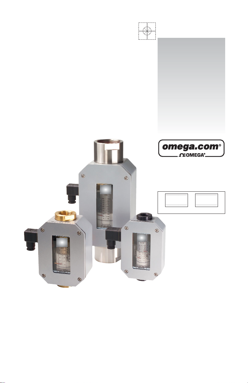
Flow Alar ms
FLMG, FLMH and FLMW Series
with -R1 or -R2 Option
User’s Guide
Shop online at
omega.com
e-mail: info@omega.com
For latest product manuals:
omegamanual.info
ISO 9001
CERTIFIED
CORPORATE QUALITY
STAMFORD, CT
ISO 9002
CERTIFIED
CORPORATE QUALITY
MANCHESTER, UK
Page 2

Servicing North America:
U.S.A.: One Omega Drive, Box 4047
ISO 9001 Certified Stamford, CT 06907-0047
Tel: (203) 359-1660 FAX: (203) 359-7700
e-mail: info@omega.com
Canada: 976 Bergar
Laval (Quebec) H7L 5A1, Canada
Tel: (514) 856-6928 FAX: (514) 856-6886
e-mail: info@omega.ca
For immediate technical or application assistance:
U.S.A. and Canada: Sales Service: 1-800-826-6342 / 1-800-TC-OMEGA
®
Customer Service: 1-800-622-2378 / 1-800-622-BEST
®
Engineering Service: 1-800-872-9436 / 1-800-USA-WHEN
®
TELEX: 996404 EASYLINK: 62968934 CABLE: OMEGA
Mexico: En Espan˜ol: (001) 203-359-7803 e-mail: espanol@omega.com
FAX: (001) 203-359-7807 info@omega.com.mx
Servicing Europe:
Benelux: Postbus 8034, 1180 LA Amstelveen, The Netherlands
Tel: +31 (0)20 3472121 FAX: +31 (0)20 6434643
Toll Free in Benelux: 0800 0993344
e-mail: sales@omegaeng.nl
Czech Republic: Frystatska 184, 733 01 Karvina´, Czech Republic
Tel: +420 (0)59 6311899 FAX: +420 (0)59 6311114
Toll Free: 0800-1-66342 e-mail: info@omegashop.cz
France: 11, rue Jacques Cartier, 78280 Guyancourt, France
Tel: +33 (0)1 61 37 2900 FAX: +33 (0)1 30 57 5427
Toll Free in France: 0800 466 342
e-mail: sales@omega.fr
Germany/Austria: Daimlerstrasse 26, D-75392 Deckenpfronn, Germany
Tel: +49 (0)7056 9398-0 FAX: +49 (0)7056 9398-29
Toll Free in Germany: 0800 639 7678
e-mail: info@omega.de
United Kingdom: One Omega Drive, River Bend Technology Centre
ISO 9002 Certified Northbank, Irlam, Manchester
M44 5BD United Kingdom
Tel: +44 (0)161 777 6611 FAX: +44 (0)161 777 6622
Toll Free in United Kingdom: 0800-488-488
e-mail: sales@omega.co.uk
OMEGAnet®Online Service Internet e-mail
omega.com info@omega.com
It is the policy of OMEGA Engineering, Inc. to comply with all worldwide safety and EMC/EMI
regulations that apply. OMEGA is constantly pursuing certification of its products to the European New
Approach Directives. OMEGA will add the CE mark to every appropriate device upon certification.
The information contained in this document is believed to be correct, but OMEGA accepts no liability for any
errors it contains, and reserves the right to alter specifications without notice.
WARNING: These products are not designed for use in, and should not be used for, human applications.
Page 3

NOTE: Refer to Omega’s “Operation & Maintenance Guide” for installation,
operation and cleaning instructions for the basic flow monitor cartridge.
The following instructions are specifically for monitors with electrical switches for
flow alarms. This is an addendum to the basic flow monitor instructions.
General Information
Omega’s Flow Alarms are typically used to make or break a set of
electrical contacts to signal a limit setting. They may be used to turn
on a warning light, sound a bell or horn, or even to shut down a
process. The switches on the alarm can be configured to open or
close a contact for an increasing or decreasing set point. Decreasing
flow set points may be located anywhere in the lower 2/3 of the scale
while increasing set points may be located anywhere in the upper
2/3 of the scale.
Overview
Illustration 1 shows the primary mechanism for a single-switch flow
alarm. Dual-switch flow alarms contain two sets of these same components, but have a slightly different electrical wiring diagram (Wiring
to the DIN connector is described on page 3.) The factory default configuration for the alarm switch is for decreasing flow, as shown in
Illustration 1. If an increasing flow alarm is desired, it
should be specified when
the unit is ordered.
The follower moves in
unison with an orifice plate
inside of the unit’s pressure
vessel via a magnetic
coupling in order to indicate
flow rate. As the follower
moves with changes in
flow rate, the flow rate is
determined by relating the
position of the flow indica-
tor line to the increments
on the flow rate scale.
(3)
Illustration 1
FOLLOWER
POINTER
SWITCH GLIDE
SCREW
ALARM
SWITCH
FLOW INDICATOR
LINE
FLOW RATE
SCALE
Page 4

The pointer indicates the set point for the alarm switch. In
Illustration 1, the switch will be actuated at all flow rates below 4
GPM. To change the set point, simply loosen the switch glide screw
one (1) turn and slide the switch to the desired position along the flow
rate scale. When the pointer is pointing to the desired flow rate, retighten the switch glide screw.
Switches
The switch is a simulated roller, lever operated low force microswitch.
The specifications for this switch are listed on page 4. The switch is
actuated when movement of the follower causes the switch lever to
be lifted. In Illustration 2, the switch has not yet been actuated, and
the electrical circuit is through the normally closed (NC) contact.
Illustration 3 shows the switch after it has been actuated. In this scenario, the electrical circuit is through the normally open (NO) contact.
Precautions
Be certain to properly ground the unit via the ground (G) pin
located on the unit’s din connector.
In order to avoid accidentally removing the switch glide screw,
never loosen it by more than one or two turns. This screw can be
difficult to replace if accidentally removed.
Avoid over tightening the switch glide screw.
When the switch adjustments are complete, make certain that the
wires that are attached to the switch have not been moved into a
location that will interfere with the follower or the switch lever.
Do not make any modifications to the unit’s internal wiring.
(4)
TRIGGER
COMMON
SWITCH LEVER
FOLLOWER
METER CASING
NO
NC
Illustration 2 Illustration 3
TRIGGER
COMMON
SWITCH LEVER
FOLLOWER
METER CASING
NO
NC
Page 5

Switches Specifications
Type Form C, dry contact
UL/CSA Rating 10 & 1/4 hp, 125 or 250 VAC
1/2 A, 125 VDC & 1/4A, 250 VDC
3A, 125 VAC “L” lamp load
Mechanical Life >10,000,000 cycles
Actuating Mechanical Simulated roller, lever operated,
low force
Connectors 3/16" tab
Double Break Switch (Special) Form Z - 10A &1/2hp,
125/250 VAC
Electrical Connections
Standard Flow Alarms
are pre-wired with 4pin Hirschmann-type
DIN connectors which
consist of a male
section as shown in
Illustration 4 and the
female section shown
in Illustration 5. To open the female section, first remove the screw,
then lift the connector portion out of the casing by inserting the head
of a screwdriver into the slot marked for that purpose. Illustration 6
shows the disassembled female section.
(5)
Illustration 4
Illustration 6
Illustration 5
Page 6

Illustration 7 shows the connections for a standard, single switch
Flow Alarm as they are shipped from the factory. The wiring for other
types of connections are outlined in the tables below. For additional
details, please consult the factory or your authorized distributor.
Alternates to the standard
Hirchmann-type DIN
connector are available on
a custom basis. The Flow
Alarm may be outfitted
with a variety of different
electrical connections
including conduit fittings,
cable-type connectors and
cord grip/pigtail interfaces.
Almost any commercially
available electrical
connector may be used.
If an alternate connector
is desired, please consult
Omega.
Wiring Code: Standard Single Switch
White - Common Terminal #1of DIN
Black - N.O. Contact Terminal #2 of DIN
Red - N.O Contact Terminal #3 of DIN
Green - Enclosure Ground Terminal “G” of DIN
Wiring Code: Dual Switch Alarm
White - Both Common Terminal #1of DIN
Black - Decreasing N.O. Contact Terminal #2 of DIN
Red - Increasing N.O. Contact Terminal #3 of DIN
Green - Enclosure Ground Terminal “G” of DIN
(6)
Illustration 7
GREEN
NO
NC
BLACK
WHITE
COMMON
RED
TO ENCLOSURE
GROUND
Page 7

Standard Control Cir cuits
(7)
Page 8

(8)
Page 9

WARRANTY/DISCLAIMER
OMEGA ENGINEERING, INC. warrants this unit to be free of defects in materials and
workmanship for a period of 13 months from date of purchase. OMEGA’s WARRANTY adds an
additional one (1) month grace period to the normal one (1) year product warranty to cover
handling and shipping time. This ensures that OMEGA’s customers receive maximum
coverage on each product.
If the unit malfunctions, it must be returned to the factory for evaluation. OMEGA’s Customer
Service Department will issue an Authorized Return (AR) number immediately upon phone or
written request. Upon examination by OMEGA, if the unit is found to be defective, it will be
repaired or replaced at no charge. OMEGA’s WARRANTY does not apply to defects resulting
from any action of the purchaser, including but not limited to mishandling, improper interfacing,
operation outside of design limits, improper repair, or unauthorized modification. This
WARRANTY is VOID if the unit shows evidence of having been tampered with or shows evidence
of having been damaged as a result of excessive corrosion; or current, heat, moisture or vibration; improper specification; misapplication; misuse or other operating conditions outside of
OMEGA’s control. Components in which wear is not warranted, include but are not limited to
contact points, fuses, and triacs.
OMEGA is pleased to offer suggestions on the use of its various products. However,
OMEGA neither assumes responsibility for any omissions or errors nor assumes liability
for any damages that result from the use of its products in accordance with information
provided by OMEGA, either verbal or written. OMEGA warrants only that the parts
manufactured by the company will be as specified and free of defects. OMEGA MAKES
NO OTHER WARRANTIES OR REPRESENTATIONS OF ANY KIND WHATSOEVER,
EXPRESSED OR IMPLIED, EXCEPT THAT OF TITLE, AND ALL IMPLIED WARRANTIES
INCLUDING ANY WARRANTY OF MERCHANTABILITY AND FITNESS FOR A PARTICULAR
PURPOSE ARE HEREBY DISCLAIMED. LIMITATION OF LIABILITY: The remedies of purchaser set forth herein are exclusive, and the total liability of OMEGA with respect to this
order, whether based on contract, warranty, negligence, indemnification, strict liability or
otherwise, shall not exceed the purchase price of the component upon which liability is
based. In no event shall OMEGA be liable for consequential, incidental or special damages.
CONDITIONS: Equipment sold by OMEGA is not intended to be used, nor shall it be used: (1) as
a “Basic Component” under 10 CFR 21 (NRC), used in or with any nuclear installation or activity;
or (2) in medical applications or used on humans. Should any Product(s) be used in or with any
nuclear installation or activity, medical application, used on humans, or misused in any way,
OMEGA assumes no responsibility as set forth in our basic WARRANTY/ DISCLAIMER language,
and, additionally, purchaser will indemnify OMEGA and hold OMEGA harmless from any liability
or damage whatsoever arising out of the use of the Product(s) in such a manner.
RETURN REQUESTS/INQUIRIES
Direct all warranty and repair requests/inquiries to the OMEGA Customer Service Department.
BEFORE RETURNING ANY PRODUCT(S) TO OMEGA, PURCHASER MUST OBTAIN AN
AUTHORIZED RETURN (AR) NUMBER FROM OMEGA’S CUSTOMER SERVICE DEPARTMENT
(IN ORDER TO AVOID PROCESSING DELAYS). The assigned AR number should then be
marked on the outside of the return package and on any correspondence.
The purchaser is responsible for shipping charges, freight, insurance and proper packaging to
prevent breakage in transit.
FOR WARRANTY
RETURNS, please have
the following information available BEFORE
contacting OMEGA:
1. Purchase Order number under which
the product was PURCHASED,
2. Model and serial number of the product
under warranty, and
3. Repair instructions and/or specific
problems relative to the product.
FOR NON-WARRANTY REPAIRS,
consult
OMEGA for current repair charges. Have the
following information available BEFORE
contacting OMEGA:
1. Purchase Order number to cover the
COST of the repair,
2. Model and serial number of the
product, and
3. Repair instructions and/or specific problems
relative to the product.
OMEGA’s policy is to make running changes, not model changes, whenever an improvement is possible.
This affords our customers the latest in technology and engineering.
OMEGA is a registered trademark of OMEGA ENGINEERING, INC.
© Copyright 2005 OMEGA ENGINEERING, INC. All rights reserved. This document may not be copied, photocopied,
reproduced, translated, or reduced to any electronic medium or machine-readable form, in whole or in part, without
the prior written consent of OMEGA ENGINEERING, INC.
Page 10

Where Do I Find Everything I Need for
Process Measurement and Control?
OMEGA…Of Course!
Shop online at omega.com
TEMPERATURE
Thermocouple, RTD & Thermistor Probes, Connectors, Panels & Assemblies
Wire: Thermocouple, RTD & Thermistor
Calibrators & Ice Point References
Recorders, Controllers & Process Monitors
Infrared Pyrometers
PRESSURE, STRAIN AND FORCE
Transducers & Strain Gages
Load Cells & Pressure Gages
Displacement Transducers
Instrumentation & Accessories
FLOW/LEVEL
Rotameters, Gas Mass Flowmeters & Flow Computers
Air Velocity Indicators
Turbine/Paddlewheel Systems
Totalizers & Batch Controllers
pH/CONDUCTIVITY
pH Electrodes, Testers & Accessories
Benchtop/Laboratory Meters
Controllers, Calibrators, Simulators & Pumps
Industrial pH & Conductivity Equipment
DATA ACQUISITION
Data Acquisition & Engineering Software
Communications-Based Acquisition Systems
Plug-in Cards for Apple, IBM & Compatibles
Datalogging Systems
Recorders, Printers & Plotters
HEATERS
Heating Cable
Cartridge & Strip Heaters
Immersion & Band Heaters
Flexible Heaters
Laboratory Heaters
ENVIRONMENTAL
MONITORING AND CONTROL
Metering & Control Instrumentation
Refractometers
Pumps & Tubing
Air, Soil & Water Monitors
Industrial Water & Wastewater Treatment
pH, Conductivity & Dissolved Oxygen Instruments
M-4156/0305
 Loading...