

Page 1
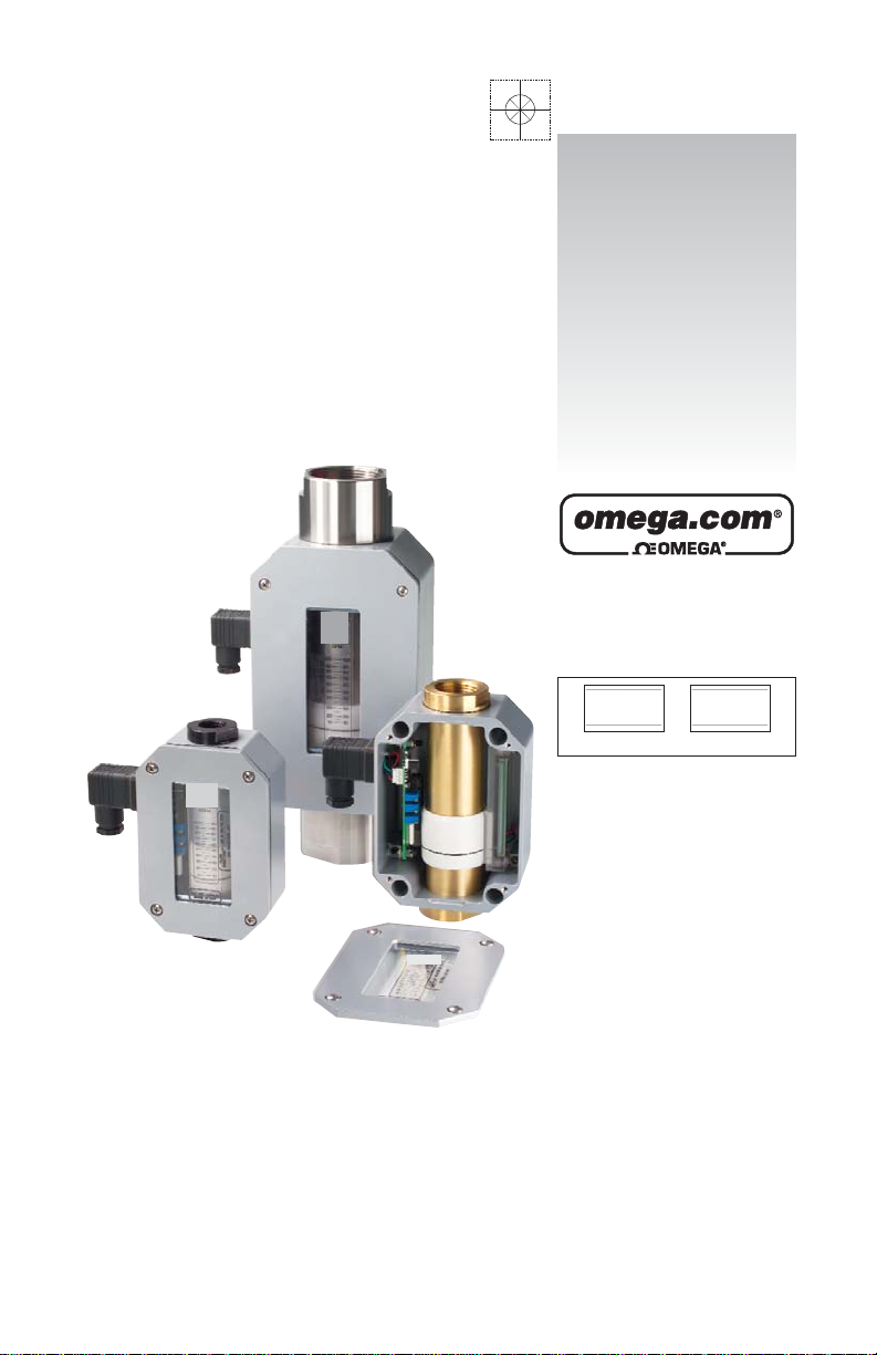
Flow Transmitter s
FLMG, FLMH and FLMW Series
with the -MA Option
User’s Guide
Shop online at
omega.com
e-mail: info@omega.com
For latest product manuals:
omegamanual.info
ISO 9001
CERTIFIED
CORPORATE QUALITY
STAMFORD, CT
ISO 9002
CERTIFIED
CORPORATE QUALITY
MANCHESTER, UK
Page 2

Servicing North America:
U.S.A.: One Omega Drive, Box 4047
ISO 9001 Certified Stamford, CT 06907-0047
Tel: (203) 359-1660 FAX: (203) 359-7700
e-mail: info@omega.com
Canada: 976 Bergar
Laval (Quebec) H7L 5A1, Canada
Tel: (514) 856-6928 FAX: (514) 856-6886
e-mail: info@omega.ca
For immediate technical or application assistance:
U.S.A. and Canada: Sales Service: 1-800-826-6342 / 1-800-TC-OMEGA
®
Customer Service: 1-800-622-2378 / 1-800-622-BEST
®
Engineering Service: 1-800-872-9436 / 1-800-USA-WHEN
®
TELEX: 996404 EASYLINK: 62968934 CABLE: OMEGA
Mexico: En Espan˜ol: (001) 203-359-7803 e-mail: espanol@omega.com
FAX: (001) 203-359-7807 info@omega.com.mx
Servicing Europe:
Benelux: Postbus 8034, 1180 LA Amstelveen, The Netherlands
Tel: +31 (0)20 3472121 FAX: +31 (0)20 6434643
Toll Free in Benelux: 0800 0993344
e-mail: sales@omegaeng.nl
Czech Republic: Frystatska 184, 733 01 Karvina´, Czech Republic
Tel: +420 (0)59 6311899 FAX: +420 (0)59 6311114
Toll Free: 0800-1-66342 e-mail: info@omegashop.cz
France: 11, rue Jacques Cartier, 78280 Guyancourt, France
Tel: +33 (0)1 61 37 2900 FAX: +33 (0)1 30 57 5427
Toll Free in France: 0800 466 342
e-mail: sales@omega.fr
Germany/Austria: Daimlerstrasse 26, D-75392 Deckenpfronn, Germany
Tel: +49 (0)7056 9398-0 FAX: +49 (0)7056 9398-29
Toll Free in Germany: 0800 639 7678
e-mail: info@omega.de
United Kingdom: One Omega Drive, River Bend Technology Centre
ISO 9002 Certified Northbank, Irlam, Manchester
M44 5BD United Kingdom
Tel: +44 (0)161 777 6611 FAX: +44 (0)161 777 6622
Toll Free in United Kingdom: 0800-488-488
e-mail: sales@omega.co.uk
OMEGAnet®Online Service Internet e-mail
omega.com info@omega.com
It is the policy of OMEGA Engineering, Inc. to comply with all worldwide safety and EMC/EMI
regulations that apply. OMEGA is constantly pursuing certification of its products to the European New
Approach Directives. OMEGA will add the CE mark to every appropriate device upon certification.
The information contained in this document is believed to be correct, but OMEGA accepts no liability for any
errors it contains, and reserves the right to alter specifications without notice.
WARNING: These products are not designed for use in, and should not be used for, human applications.
Page 3
NOTE: Refer to Omega’s “Operation & Maintenance Guide” for installation,
operation and cleaning instructions for the basic flow monitor cartridge.
The following instructions are specifically for monitors with electrical switches
for flow alarms. This is an addendum to the basic flow monitor instructions.
General Information
Omega’s Flow Transmitters are typically used to transmit a signal
proportional to flow rate to a process control computer, a PLC, a
recorder, or a panel-mount display. The Flow Transmitters are used
as the primary input device to record flow rates through hydraulic and
pneumatic systems.
The universal output transmitter circuit employed by the Omega Flow
Transmitter is capable of producing output signals of 4-20 mA, 0-5
VDC, and 0-2000 Hz square wave pulse. A1-5 VDC signal may be
obtained by placing a 249
Ω resistor within the 4-20 mA loop.
Overview
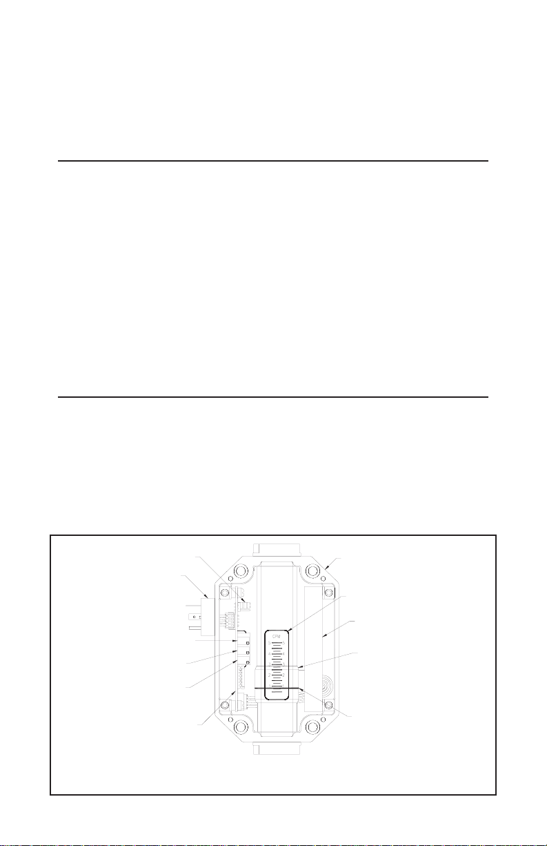
Illustration 1 shows a Flow Transmitter with the cover removed.
The follower moves in unison with an orifice plate inside of the unit’s
pressure vessel via a magnetic coupling in order to indicate flow rate.
As the follower moves with changes in flow rate, the flow rate is
determined by relating the position of the flow indicator line to the
increments on the flow rate scale.
(3)
Illustration 1
PROGRAMMABLE JUMPER
NEMA 4X ENCLOSURE
SENSOR ASSEMBLY
FOLLOWER
FLOW INDICATOR LINE
FLOW RATE SCALE
DIN CONNECTOR
4-20 mA OFFSET ADJUST
4-20 mA SPAN ADJUST
0-5 VDC SPAN ADJUST
SIGNAL CONDITIONING CIRCUIT
Page 4

The sensor array located in the sensor assembly sends a signal
relative to the position of the follower to the signal conditioning circuit.
The signal conditioning circuit converts the signal from the sensor
array into three different signals that are all directly proportional to the
reading that is determined by relating the position of the flow indicator
line to the flow rate scale.
The user may choose between reading a 0-2000 Hz square wave
pulse, a 0-5 VDC analog signal, or a two-wire 4-20 mA analog signal
by connecting to the appropriate pins on the 4-pin Hirschmann® din
connector and by placing the programmable jumper in the appropriate
position for the desired output.
An analog 1-5 VDC output may also be obtained by configuring the unit
for the two-wire 4-20 mA output and then placing a 249W ohm resistor
in the current loop. The exact output pins and jumper positions that
correspond to each output are discussed later in this manual.
4-20 mA Output Connections
Input Voltage:
The supply voltage must be between 12 and 35 VDC.The maximum
resistance that may be placed within the current loop is given by the
following formula:
Where: R
max
= the maximum resistance that may be placed in the
current loop (
Ω)
Vs= the value of the supply voltage (VDC)
(4)
R
max
= 50(Vs- 12)
Page 5

4-20 mA Output Connections
Wiring Instructions (Refer to Illustrations 2 and 3 above):
1) Move the programmable jumper on the signal conditioning
board into the position closest to the meter’s outlet, as shown
in Illustration 3.
2) Connect the positive DC power source (+12 to +35 VDC) to
terminal #1 on the din connector
3) Connect terminal #2 of the din connecter to the positive current
input on the receiving device.
4) If the power source does not originate from the receiving device,
the negative side of the power supply must be connected to the
signal ground of the receiving device.
5) If the transmitter is operating properly, the green LED on the
signal conditioning board will illuminate dimly at zero flow and
will increase in intensity as flow increases.
(5)
Illustration 2 Illustration 3
PROGRAMMABLE JUMPER
IN POSITION CLOSEST
TO METER OUTLET
JUMPER POSITION - 4-20 mA
ELECTRICAL CONNECTION - 4-20 mA
NO CONNECTION
PIN #1
+12 - 35 VDC
PIN #2
4 - 20 mmA OUT
NO CONNECTION
Page 6

0-5 VDC Output Connections
Wiring Instructions (Refer to Illustrations 4 and 5 above):
1) Move the programmable jumper on the circuit board into the
position closest to the meter’s inlet, as shown in Illustration 5.
2) Connect the positive voltage source (+12 to +35 VDC) to terminal
#1 of the din connector.
3) Connect terminal #2 of the din connector to the negative side of
the DC voltage source.
4) Connect terminal #3 of the din connector to the 0-5 VDC input of
the receiving device.
5) If the power source does not originate at the receiving device, a
wire will need to be connected between the negative side of the
voltage source and the signal ground of the receiving device.
6) If the transmitter is operating correctly, the green LED on the
circuit board will illuminate brightly when power is applied to the
unit.
NOTE: The input impedance (resistance) of the receiving device
must not be lower than 100W or non-linearities may result.
Lower impedance will not damage the transmitter.
(6)
Illustration 4
Illustration 5
PROGRAMMABLE JUMPER
IN POSITION CLOSEST
TO METER INLET
JUMPER POSITION - 4-20 mA
PIN #3
0 - 5 VDC OUTPUT
ELECTRICAL CONNECTIONS - 0 - 5VDC
NO CONNECTION
PIN #1
+12 - 35 VDC
PIN #2
DC GROUND
Page 7

0-2000 Hz Pulse Output Connections
Wiring Instructions (Refer to Illustrations 6 and 7 above):
1) Move the programmable jumper on the circuit board into the
position closest to the meter’s inlet, as shown in Illustration 7.
2) Connect the positive voltage source (+12 to +35 VDC) to terminal
#1 of the din connector.
3) Connect terminal #2 of the din connector to the negative side
of the DC voltage source.
4) Connect the “G” terminal of the din connector to the pulse input
of the receiving device.
5) If the power source does not originate at the receiving device, a
wire will need to be connected between the negative side of the
voltage source and the signal ground of the receiving device.
6) If the transmitter is operating properly, the green LED on the circuit
board will illuminate brightly when power is applied to the unit.
(7)
Illustration 6 Illustration 7
PROGRAMMABLE JUMPER
IN POSITION CLOSEST
TO METER INLET
JUMPER POSITION - 0-2000Hz PULSE OUTPUT
NO CONNECTION
ELECTRICAL CONNECTIONS - 0-2000Hz OUTPUT
“G” PIN
0-2000Hz OUTPUT
PIN #1
+12 - 35 VDC
PIN #2
DC GROUND
Page 8

1-5 VDC Output Connections
Wiring Instructions (Refer to Illustrations 8 and 9 above):
1) Move the programmable jumper on the signal conditioning board
into the position closest to the meter’s outlet, as shown in
Illustration 9.
2) Connect the positive voltage (+17 to +35 VDC) to terminal #1 of
the din connector.
3) Connect terminal #2 of the DIN to the 1-5 VDC input of the
receiving device.
4) If the power source does not originate at the receiving device, a
wire will need to be connected between the negative side of the
voltage source and the signal ground of the receiving device.
5) If the transmitter is operating properly, the green LED on the
circuit board will illuminate dimly at zero flow and will increase in
intensity as flow rate increases.
(8)
Illustration 8 Illustration 9
NO CONNECTION
ELECTRICAL CONNECTIONS - 1- 5 VDC
NO CONNECTION
249 OHMS
PIN #1
+17 - 35 VDC
PIN #2
1-5 VDC OUT
TO SIGNAL
GROUND
PROGRAMMABLE JUMPER
IN POSITION CLOSEST
TO METER OUTLET
JUMPER POSITION - 1- 5 VDC
Page 9

Connectors
Standard flow sensors are prewired with 4-wire Hirschmann-type DIN
connectors which consist of a male section as shown in Illustration 10
and a female section as shown in Illustration 11. In order to make the
user connections, the screw terminals located inside of the female
section must be accessed.
To open the female
section, first
remove the screw
and then lift the
connector portion
out of the casing by
inserting the head
of a screwdriver
into the slot marked
for that purpose.
Illustration 12
shows the disassembled female
section. The screw
terminal connections can be seen
on the piece located
at the far right side
of the illustration.
Alternate connectors are available on a custom basis. Nearly any
type of commercially available electrical connector may be installed
on an Omega Flow Transmitter. If an alternate connector is required,
please consult the Omega factory.
(9)
Illustration 10 Illustration 11
Illustration 12
Page 10

User Adjustments
The 4-20 mA, 0-5V, and 0-2000 Hz square wave outputs on the
Omega Flow Transmitter are all factory calibrated. User adjustment
should be unnecessary and any adjustment of the potentiometer on
the signal conditioning board is strongly discouraged. If one of the
outputs does fall out of calibration, the following procedure may be
used to recalibrate the unit.
1) Turn off the flow through the system.
2) Connect between +12 and +35 VDC to pin 1 of the din connector.
Connect terminal 2 of the din connector to the negative terminal
of the DC supply.
3) Move the programmable jumper on the signal conditioning
board into the position closest to the sensor’s inlet, as shown in
Illustrations 5 and 7.
4) Connect the positive terminal of a voltmeter to pin 3 of the din
connector. Connect the negative terminal to pin 2 of the din
connector.
5) Gradually increase the flow through the system until the flow rate
indicated on the printed flow rate scale reaches full-scale (the
highest value printed on the scale).
6) Adjust the 0-5 VDC Span potentiometer until a reading of
5.00 VDC is obtained on the voltmeter.
7) Turn off the flow through the system and remove the voltmeter.
8) Move the programmable jumper on the signal conditioning board
into the position closest to the sensor’s outlet, as shown in
Illustrations 3 and 9.
9) Disconnect pin 1 of the din connector from the positive terminal of
the DC power supply.
10) Connect the positive terminal of an ammeter to the positive
terminal of the DC power supply. Connect the negative terminal
of the ammeter to pin 1 of the sensor’s din connector.
11) Adjust the 4-20 mA Offset potentiometer (see Illustration 1) until
a reading of 4.00 mA is obtained on the ammeter.
(10)
Page 11

12) Gradually increase the flow through the system until the flow rate
indicated on the printed flow rate scale reaches full-scale (the
highest value printed on the scale).
13) Adjust the 4-20 mA span potentiometer (see Illustration 1) until a
reading of 20.00 mA is obtained on the ammeter.
14) Gradually decrease the flow through the system until a value
equal to 50% of full-scale is obtained on the sensor’s flow rate
scale. Verify a reading of between 11.92 and 12.08 mA.
(11)
Trouble Shooting
Symptom Solution
The green LED does not
illuminate when power is
applied.
1) Re-check the wiring diagram for the
communication protocol that is being
used and verify that the wiring is correct.
2) Verify that the DC supply that is being
used is capable of producing at least
12 VDC.
3) Make sure that the cable that is
soldered to the din connector inside
of the sensor enclosure is plugged
into the connector opposite to the
programmable jumper.
The readings obtained from the
electronic output do not agree
with the readings shown on the
printed flow rate scale.
1) Make sure that the programmable
jumper is in the correct position for
the communication protocol that is
being used.
The green LED illuminates, but
no readings are obtained from
the sensor’s electronic output.
1) Re-check the wiring diagram for the
communication protocol that is being
used and verify that the wiring is correct.
2) Make sure that the cable from the sensor
assembly is plugged into the connect on
the signal conditioning board located
near the sensor inlet.
When the flow rate in the
systems changes, the follower
and electronic output do not
respond.
1) Remove the flow sensor from the
hydraulic systems and inspect the
intervals to see if anything has caused
them to become jammed. Make sure
that the 200 mesh, 74 micron filtration
requirement of the flow sensor is being
observed.
Page 12

NOTES:
_ _ _ _ _ _ _ _ _ _ _ _ _ _ _ _ _ _ _ _ _ _ _ _ _ _ _ _ _ _ _ _ _ _ _ _ _ _ _ _ _ _ _ _ _ _ _ _ _ _ _ _ _ _ _
_ _ _ _ _ _ _ _ _ _ _ _ _ _ _ _ _ _ _ _ _ _ _ _ _ _ _ _ _ _ _ _ _ _ _ _ _ _ _ _ _ _ _ _ _ _ _ _ _ _ _ _ _ _ _
_ _ _ _ _ _ _ _ _ _ _ _ _ _ _ _ _ _ _ _ _ _ _ _ _ _ _ _ _ _ _ _ _ _ _ _ _ _ _ _ _ _ _ _ _ _ _ _ _ _ _ _ _ _ _
_ _ _ _ _ _ _ _ _ _ _ _ _ _ _ _ _ _ _ _ _ _ _ _ _ _ _ _ _ _ _ _ _ _ _ _ _ _ _ _ _ _ _ _ _ _ _ _ _ _ _ _ _ _ _
_ _ _ _ _ _ _ _ _ _ _ _ _ _ _ _ _ _ _ _ _ _ _ _ _ _ _ _ _ _ _ _ _ _ _ _ _ _ _ _ _ _ _ _ _ _ _ _ _ _ _ _ _ _ _
_ _ _ _ _ _ _ _ _ _ _ _ _ _ _ _ _ _ _ _ _ _ _ _ _ _ _ _ _ _ _ _ _ _ _ _ _ _ _ _ _ _ _ _ _ _ _ _ _ _ _ _ _ _ _
_ _ _ _ _ _ _ _ _ _ _ _ _ _ _ _ _ _ _ _ _ _ _ _ _ _ _ _ _ _ _ _ _ _ _ _ _ _ _ _ _ _ _ _ _ _ _ _ _ _ _ _ _ _ _
_ _ _ _ _ _ _ _ _ _ _ _ _ _ _ _ _ _ _ _ _ _ _ _ _ _ _ _ _ _ _ _ _ _ _ _ _ _ _ _ _ _ _ _ _ _ _ _ _ _ _ _ _ _ _
_ _ _ _ _ _ _ _ _ _ _ _ _ _ _ _ _ _ _ _ _ _ _ _ _ _ _ _ _ _ _ _ _ _ _ _ _ _ _ _ _ _ _ _ _ _ _ _ _ _ _ _ _ _ _
_ _ _ _ _ _ _ _ _ _ _ _ _ _ _ _ _ _ _ _ _ _ _ _ _ _ _ _ _ _ _ _ _ _ _ _ _ _ _ _ _ _ _ _ _ _ _ _ _ _ _ _ _ _ _
_ _ _ _ _ _ _ _ _ _ _ _ _ _ _ _ _ _ _ _ _ _ _ _ _ _ _ _ _ _ _ _ _ _ _ _ _ _ _ _ _ _ _ _ _ _ _ _ _ _ _ _ _ _ _
_ _ _ _ _ _ _ _ _ _ _ _ _ _ _ _ _ _ _ _ _ _ _ _ _ _ _ _ _ _ _ _ _ _ _ _ _ _ _ _ _ _ _ _ _ _ _ _ _ _ _ _ _ _ _
_ _ _ _ _ _ _ _ _ _ _ _ _ _ _ _ _ _ _ _ _ _ _ _ _ _ _ _ _ _ _ _ _ _ _ _ _ _ _ _ _ _ _ _ _ _ _ _ _ _ _ _ _ _ _
_ _ _ _ _ _ _ _ _ _ _ _ _ _ _ _ _ _ _ _ _ _ _ _ _ _ _ _ _ _ _ _ _ _ _ _ _ _ _ _ _ _ _ _ _ _ _ _ _ _ _ _ _ _ _
_ _ _ _ _ _ _ _ _ _ _ _ _ _ _ _ _ _ _ _ _ _ _ _ _ _ _ _ _ _ _ _ _ _ _ _ _ _ _ _ _ _ _ _ _ _ _ _ _ _ _ _ _ _ _
_ _ _ _ _ _ _ _ _ _ _ _ _ _ _ _ _ _ _ _ _ _ _ _ _ _ _ _ _ _ _ _ _ _ _ _ _ _ _ _ _ _ _ _ _ _ _ _ _ _ _ _ _ _ _
_ _ _ _ _ _ _ _ _ _ _ _ _ _ _ _ _ _ _ _ _ _ _ _ _ _ _ _ _ _ _ _ _ _ _ _ _ _ _ _ _ _ _ _ _ _ _ _ _ _ _ _ _ _ _
_ _ _ _ _ _ _ _ _ _ _ _ _ _ _ _ _ _ _ _ _ _ _ _ _ _ _ _ _ _ _ _ _ _ _ _ _ _ _ _ _ _ _ _ _ _ _ _ _ _ _ _ _ _ _
_ _ _ _ _ _ _ _ _ _ _ _ _ _ _ _ _ _ _ _ _ _ _ _ _ _ _ _ _ _ _ _ _ _ _ _ _ _ _ _ _ _ _ _ _ _ _ _ _ _ _ _ _ _ _
(12)
Page 13

WARRANTY/ DISCLAIMER
OMEGA ENGINEERING, INC. warrants this unit to be free of defects in materials and
workmanship for a period of 13 months from date of purchase. OMEGA’s WARRANTY adds an
additional one (1) month grace period to the normal one (1) year product warranty to cover
handling and shipping time. This ensures that OMEGA’s customers receive maximum
coverage on each product.
If the unit malfunctions, it must be returned to the factory for evaluation. OMEGA’s Customer
Service Department will issue an Authorized Return (AR) number immediately upon phone or
written request. Upon examination by OMEGA, if the unit is found to be defective, it will be
repaired or replaced at no charge. OMEGA’s WARRANTY does not apply to defects resulting
from any action of the purchaser, including but not limited to mishandling, improper interfacing,
operation outside of design limits, improper repair, or unauthorized modification. This
WARRANTY is VOID if the unit shows evidence of having been tampered with or shows evidence
of having been damaged as a result of excessive corrosion; or current, heat, moisture or vibration; improper specification; misapplication; misuse or other operating conditions outside of
OMEGA’s control. Components in which wear is not warranted, include but are not limited to
contact points, fuses, and triacs.
OMEGA is pleased to offer suggestions on the use of its various products. However,
OMEGA neither assumes responsibility for any omissions or errors nor assumes liability
for any damages that result from the use of its products in accordance with information
provided by OMEGA, either verbal or written. OMEGA warrants only that the parts
manufactured by the company will be as specified and free of defects. OMEGA MAKES
NO OTHER WARRANTIES OR REPRESENTATIONS OF ANY KIND WHATSOEVER,
EXPRESSED OR IMPLIED, EXCEPT THAT OF TITLE, AND ALL IMPLIED WARRANTIES
INCLUDING ANY WARRANTY OF MERCHANTABILITY AND FITNESS FOR A PARTICULAR
PURPOSE ARE HEREBY DISCLAIMED. LIMITATION OF LIABILITY: The remedies of purchaser set forth herein are exclusive, and the total liability of OMEGA with respect to this
order, whether based on contract, warranty, negligence, indemnification, strict liability or
otherwise, shall not exceed the purchase price of the component upon which liability is
based. In no event shall OMEGA be liable for consequential, incidental or special damages.
CONDITIONS: Equipment sold by OMEGA is not intended to be used, nor shall it be used: (1) as
a “Basic Component” under 10 CFR 21 (NRC), used in or with any nuclear installation or activity;
or (2) in medical applications or used on humans. Should any Product(s) be used in or with any
nuclear installation or activity, medical application, used on humans, or misused in any way,
OMEGA assumes no responsibility as set forth in our basic WARRANTY/ DISCLAIMER language,
and, additionally, purchaser will indemnify OMEGA and hold OMEGA harmless from any liability
or damage whatsoever arising out of the use of the Product(s) in such a manner.
RETURN REQUESTS/INQUIRIES
Direct all warranty and repair requests/inquiries to the OMEGA Customer Service Department.
BEFORE RETURNING ANY PRODUCT(S) TO OMEGA, PURCHASER MUST OBTAIN AN
AUTHORIZED RETURN (AR) NUMBER FROM OMEGA’S CUSTOMER SERVICE DEPARTMENT
(IN ORDER TO AVOID PROCESSING DELAYS). The assigned AR number should then be
marked on the outside of the return package and on any correspondence.
The purchaser is responsible for shipping charges, freight, insurance and proper packaging to
prevent breakage in transit.
FOR WARRANTY
RETURNS, please have
the following information available BEFORE
contacting OMEGA:
1. Purchase Order number under which
the product was PURCHASED,
2. Model and serial number of the product
under warranty, and
3. Repair instructions and/or specific
problems relative to the product.
FOR NON-WARRANTY REPAIRS,
consult
OMEGA for current repair charges. Have the
following information available BEFORE
contacting OMEGA:
1. Purchase Order number to cover the
COST of the repair,
2. Model and serial number of the
product, and
3. Repair instructions and/or specific problems
relative to the product.
OMEGA’s policy is to make running changes, not model changes, whenever an improvement is possible.
This affords our customers the latest in technology and engineering.
OMEGA is a registered trademark of OMEGA ENGINEERING, INC.
© Copyright 2005 OMEGA ENGINEERING, INC. All rights reserved. This document may not be copied, photocopied,
reproduced, translated, or reduced to any electronic medium or machine-readable form, in whole or in part, without
the prior written consent of OMEGA ENGINEERING, INC.
Page 14

Where Do I Find Everything I Need for
Process Measurement and Control?
OMEGA…Of Course!
Shop online at omega.com
TEMPERATURE
Thermocouple, RTD & Thermistor Probes, Connectors, Panels & Assemblies
Wire: Thermocouple, RTD & Thermistor
Calibrators & Ice Point References
Recorders, Controllers & Process Monitors
Infrared Pyrometers
PRESSURE, STRAIN AND FORCE
Transducers & Strain Gages
Load Cells & Pressure Gages
Displacement Transducers
Instrumentation & Accessories
FLOW/LEVEL
Rotameters, Gas Mass Flowmeters & Flow Computers
Air Velocity Indicators
Turbine/Paddlewheel Systems
Totalizers & Batch Controllers
pH/CONDUCTIVITY
pH Electrodes, Testers & Accessories
Benchtop/Laboratory Meters
Controllers, Calibrators, Simulators & Pumps
Industrial pH & Conductivity Equipment
DATA ACQUISITION
Data Acquisition & Engineering Software
Communications-Based Acquisition Systems
Plug-in Cards for Apple, IBM & Compatibles
Datalogging Systems
Recorders, Printers & Plotters
HEATERS
Heating Cable
Cartridge & Strip Heaters
Immersion & Band Heaters
Flexible Heaters
Laboratory Heaters
ENVIRONMENTAL
MONITORING AND CONTROL
Metering & Control Instrumentation
Refractometers
Pumps & Tubing
Air, Soil & Water Monitors
Industrial Water & Wastewater Treatment
pH, Conductivity & Dissolved Oxygen Instruments
M-4157/0305
 Loading...