

Page 1
INSTALLATION, OPERATION
& MAINTENANCE INSTRUCTIONS
AIR COOLED CONDENSERS
FLUID COOLERS
HEAT RECLAIM UNITS
Page 2
CONTENT
SAFETY CONSIDERATIONS .........................2
INTRODUCTION..............................................2
HANDLING.......................................................3
INSTALLATION ...............................................3
STEPS #1 INSPECTION/LOCATION:..3
STEP #3 WIRING:.........................................3
STEPS #4 PIPING/LEAK TESTING ....3
OPERATION .....................................................4
FAN MOTORS/FAN CYCLING...................4
MAINTENANCE - CLEANING .......................4
TABLE 1: FLUID COOLERS: ..........................5
TABLE 2: CONDENSER & HEAT
RECLAIM ............................................6 to 16
Fig # 1: Standard legs .......................................17
Condenser/Fluid Cooler Dimensions........18& 19
Fig. #2 : Extended Legs....................................20
Fig #3 : 2 fans ...................................................21
Fig # 4: 1 fan ....................................................22
Table #3............................................................23
Table #4............................................................24
Table #5............................................................25
Table #6............................................................26
Table #7............................................................27
Replacement part list…………………... 28 & 29
WARRANTIES................................................30
SAFETY CONSIDERATIONS
Installing, starting up, and servicing
equipment can be hazardous due to system
pressures, electrical components and equipment
location (roofs, elevated structures, etc.). Only
trained, qualified installers and service
mechanics should install, start up, and service
this equipment.
When working on the equipment, observe
precautions in the literature and on the tags,
stickers, and labels attached to the equipment.
Follow all safety codes. Wear safety glasses
and work gloves. Keep quenching cloths and fire
extinguisher nearby when brazing. Use care in
handling, rigging, and setting bulky equipment.
WARNING
Before installation, always check to be sure
main power to systems is OFF. Electrical
shock can cause personal injury or death.
INTRODUCTION
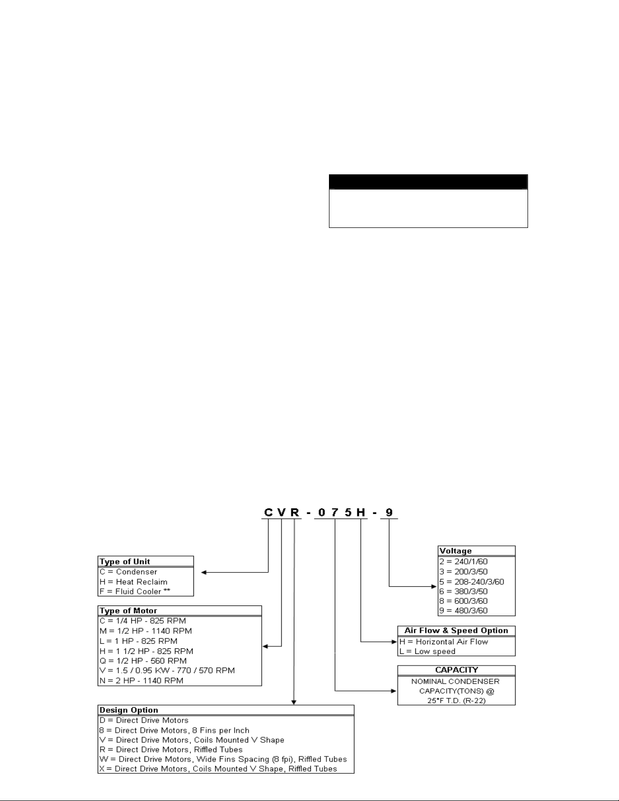
Air Cooled condensers series CCR, CMR, CLR,
CLW, CLX, CNR, CNW, CNX, CVR, CVW,
CVX, CCD, CQD, CLD, CMD, CH8, CL8,
CHD and CID are designed for refrigerant
condensing of refrigeration and air conditioning
systems. They can be manufactured for single or
multiple circuits, for single or multiple
compressors.
Fluid coolers series FCD, FLD, FID, FMD,
FNV, FVD, FVV and FND are designed to cool
glycol, oil or any other fluid that is not corrosive
to copper and will not let the leaving air
temperature exceed 140°F (60°C).
Heat recovery units HCD and HMD are designed
to recover heat from refrigeration system in
warehouse or shipping area.
2
Page 3
HANDLING
CAUTION : Do not use forklift truck to
handle units. Use only chains with hooks and
spread bars to lift units.
When a unit is shipped on its side, two or three
hangers are installed. Use them to unload the
unit from truck.
A lift truck can be used with the wood base in
that position only to lower the unit on the
ground.
Two others hangers, four, six or eight legs
(depending on the unit) and the required
hardware are supplied attached to the cabinet.
Lifting method 1 :
• Install all the legs on the same side as
hangers.
• Gently lower the unit on those legs.
• Install hangers on opposite side.
• Raise the other side and install other legs.
• Install chains and spread bars to raise the
unit to its final position.
Lifting method 2 :
• Gently lower the unit on a flat surface.
• Install hangers on opposite side.
• Install chains and spread bars to raise the
unit.
• Lift the unit and install all the legs.
• Lift the unit to it’s final position.
See fig # 1 for more details. If the unit as been
ordered with extended legs, see fig. #2 for field
assembly. Also refer to table #1, #2 for unit
weight.
INSTALLATION
STEP #1 INSPECTION:
If the unit is suspected of having been damaged
in transit, immediately notify the carrier and file
a claim with that carrier. The refrigeration coil
section(s) of the unit should display a pressurised
nitrogen gas holding charge. Unit should then be
pressurised to 350 psi with dry nitrogen gas and
leak-checked prior to rigging; this to insure no
coil damage has occurred after the unit left the
factory. Bolts & nuts may have become loose in
transit, as well as electrical components. Please
make sure that everything is tight prior to startup.
STEP #2 LOCATION:
Condensers and fluid coolers are installed on the
roof or ground level. If a unit is installed on the
ground it must be fenced to prevent possible
damage. Heat recovery units are installed inside
at the ceiling level. Check loading capacity of the
roof, the ceiling or the floor before installation.
The unit is intended to be installed in an
atmosphere containing only neutral water
vapour, natural precipitation and air. Use in any
other atmosphere must be checked for
compatibility with metals, materials and coating
used in manufacturing of this equipment.
Unit positioning as well as firmness and perfect
levelness of mounting base supports are
important: Good installation practices are well
known and are to be followed. Air flow paths on
all sides as well as coil inlet and fan discharge
areas are not to be restricted. Unit positioning
that may result in air recirculation as well as
prevailing wind impedance is to be avoided.
If a unit is to be placed close to a wall the
minimum distance should be 24 inches for single
row of fans and 48 inches for double row of fans.
If units are to be placed side by side, the
minimum distances should be 48 inches for
single row of fans and 96 inches for a double
row of fans. The chosen location must be
convenient and allow safe accessibility for
maintenance.
STEP #3 WIRING:
NOTE: A wiring diagram is provided with the
unit, it is located on the inner face of the
electrical box access door.
All wiring must be done in accordance with
national and local codes. Check the nameplate
with the current characteristics to be used for
wiring unit. Internal wiring connections of the
fan motors, optional controls and contactors have
been completed at the factory. Once wired, make
sure the unit has been grounded. Disconnect
switch at the unit must be provided by others.
On air cooled condensers with flooding valve,
one fan (single width unit) or one pair of fans
(double width unit) must operate when
compressor is operating to avoid internal damage
to the condenser coil.
3
Page 4
STEP #4 PIPING:
probably occur.
CAUTION: The unit has not been designed to
carry the weight of any extended piping or
valves. The piping must be well supported
otherwise tube breaking at the coil will most
All refrigerant or fluid system components must
be installed in accordance with applicable local
and national codes and in accordance with good
engineering practice required for proper
operation.
Use top quality refrigeration tubing that is
internally free of dirt, humidity or other
contaminants. Unsealed tubing should not be
used. Long radius elbows are recommended.
Dry nitrogen must be swept through the lines
while joints are brazed to avoid oxidation and
carbon deposits.
IMPORTANT: The use of a calibrated
pressure gage and regulator must always be
used with nitrogen gas cylinders.
To minimise hydraulic shock line breakage
possibilities, valving and controls must be
designed to eliminate any rapid introduction of
hot gas into cold piping. Most especially if the
piping contains liquid refrigerant or is at a much
lower pressure than the hot discharge gas, which
can be the case of double-wide condensers that
feature one-half operation during winter. Plans
should be for utilising either a slow-shifting
three-way/four-way valve, or not completely
lowering to suction pressure the condenser coil
side that deactivates during winter. Most often, a
combination of both of these options works well
in geographic areas that encounter lower than
freezing seasonal outdoor temperatures.
Air-cooled condensers must be provided with
inverted “P” trap with a purge connection. A
separate sub cooling circuit may be necessary if
liquid line must rise to level higher than the unit.
Vibration in the discharge or liquid line must be
corrected immediately to avoid piping and/or
header breakage and refrigerant loss.
Generally, horizontal-piping runs should grade
slightly downwards in the direction of the flow.
Liquid line piping must be arranged so that it is
free draining from the condenser to the receiver.
It is best to pipe liquid lines so that there is an
immediate drop, at least 2 or 3 feet, at the
condenser outlet, before headering or running
horizontally.
STEP #5 LEAK TESTING:
Leak testing and evacuation must be done in
accordance with local and national codes.
Once all refrigerant connections are made, leak
test all joints before charging the system with
refrigerant. After leak testing, all moisture and
non-condensable gas must be evacuated from the
system. Attach high vacuum line pump and gage
on both high and low pressure sides of the
system. A minimum vacuum level of 100
microns is required to effectively remove
moisture.
Be sure all valves such as compressor, hot gas,
receiver, and liquid solenoid valves are open.
Break the vacuum in the system with the
refrigerant to be used. Always charge the
refrigerant into the system through a new 16 cu.
in drier (field supplied) in the charging manifold
line.
OPERATION
The notice below depicts the label that is affixed
to the control box cover.
WARNING
ONE FAN (SINGLE WIDTH UNIT) OR ONE
PAIR OF FANS (DOUBLE WIDTH UNIT)
OPERATE SIMULTANEOUSLY TO AVOID
Not complying to this condition can cause
uneven rapid expansion and contraction of the
condenser core tubing contributing to condenser
tubes failures. Violation of this condition will
void the warranty of the misused unit.
For a refrigeration system to function properly,
the condensing pressure and temperature must be
maintained within certain limits.
To prevent excessively low head pressure during
winter operation, two basic control methods are
used, refrigerant side control and air side control.
Warranty Condition
AND THE COMPRESSOR MUST
DAMAGE TO THE CONDENSER COIL.
4
Page 5

1) A) Refrigerant-side control is accomplished
by modulating the amount of active
condensing surface available for condensing
by flooding the coil with liquid refrigerant.
This method requires a receiver and a larger
charge of refrigerant. See fig. #3.
B) Refrigerant-side control by doing the
one-half condenser operation. The
condenser is initially resigned with two
equal sections, each accommodating 50% of
the load during normal operation.
During winter an ambient controlled flow
divider valve blocks off one section of the
condenser and pumps down the inactive
section in the suction. This saves the
flooding overcharge and sometimes allows
the shutdown of the fans on the inactive
condenser side. Fig. #4
2) Airside control is accomplished by cycling
fans in response to condensing pressure or
outdoors-ambient temperature. To reduce
stress on the condenser coil, one fan or one
pair of fans must operate when a condenser
is operating. Speed control on the constant
operating fan may be used to reduce motor
cycling and stabilise the operating pressure.
See table 3 to 6 for more information.
For low ambient operation this method must be
combined with refrigerant side control.
FAN MOTORS:
Check the fan blade clearances within the
venturies, as well as check for proper rotation.
Fan motors operating at higher elevations will
draw lower than rated amp as well as draw less
effective air volume across the coil surface. This
is due to the reduced density of the higher
altitude air, which results in higher compressor,
and higher discharge pressure along with
reduced unit capacity. Please consult factory if
you suspect this situation.
The fan motors are permanently lubricated for
service free operation. The motor may restart on
automatic thermal protection. Motors are readily
serviced by removing fan guards and fans. If a
motor is inoperative or it cycles on thermal
protection, check supply voltage at the motor
leads. Fan motors may cycle on thermal
protection if the coil is blocked.
Units equipped with axial fans, CVR, CVW,
CVX: The entire fan assembly, motor, blade and
ventury need to be replaced if there is a failure of
any kind. With the two speed version, 3
contactors are used per motor. Do not attempt to
manually close one of these contactors; this may
result in motor winding damage.
FAN CYCLING:
Optional temperature or pressure controls are
located in the control box. Air temperature
sensors are located in the air flow and pressure
controls are directly connected to the circuit in a
return bend.
Optional line duty controls are connected
directly to the fan motors. Controls are double
pole single throw, one line remain live on the
motors. Units must be completely disconnected
before servicing.
Optional pilot duty controls are connected to 3
pole motor contactors. If controls or contactors
are defective, they must be replaced.
MAINTENANCE
CLEANING:
After one day of operation, check for any
vibration that might have developed in the unit.
It is recommended that the unit be inspected
occasionally for dirt accumulation. Grease and
dust should be removed from the fans and fan
guards.
Periodical cleaning of finned surfaces can be
done by washing down dust with warm water
spray and a mild detergent. Do not use alkaline
or acidic solution as it will attack the coil
material.
The inner face of the coil may be cleaned by the
access panel on the side of the units or by
removing the fan guards.
Always pressure -clean in reverse of the air flow.
5
Page 6
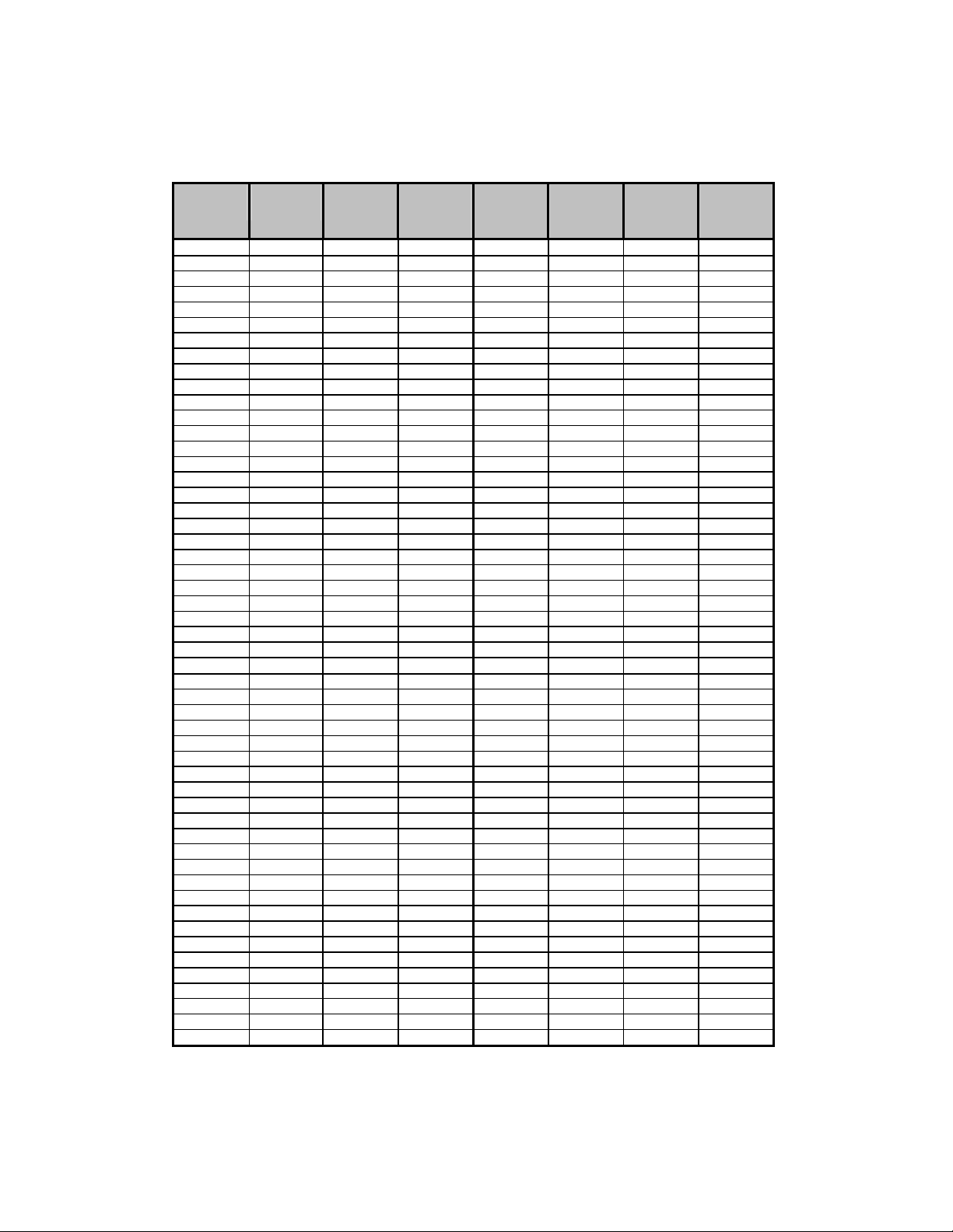
TABLE 1: FLUID COOLERS
Fluid
CoolerID
FCD02 1 1 190 FLD015 1 1 654
FCD03 1 1 201 FLD018 1 2 985
FCD04 1 1 210 FLD021 1 2 1005
FID010 1 1 515 FLD023 1 2 1063
FID011 1 1 525 FLD026 1 2 1091
FID013 1 1 592 FLD028 1 2 1117
FID014 1 1 602 FLD030 1 2 1159
FID016 1 1 641 FLD035 1 3 1460
FID017 1 1 654 FLD040 1 3 1490
FID020 1 2 985 FLD042 2 2 1625
FID023 1 2 1005 FLD043 1 3 1570
FID025 1 2 1063 FLD045 1 3 1609
FID029 1 2 1091 FLD049 2 2 1792
FID031 1 2 1117 FLD050 1 4 1875
FID034 1 2 1159 FLD053 2 2 1781
FID039 1 3 1460 FLD054 1 4 1915
FID044 1 3 1490 FLD056 2 2 1882
FID046 2 2 1625 FLD057 1 4 2019
FID049 1 3 1570 FLD060 2 2 1934
FID051 1 3 1609 FLD061 1 4 2071
FID054 2 2 1792 FLD063 2 3 2323
FID055 1 4 1875 FLD066 1 5 2403
FID058 2 2 1781 FLD070 1 5 2475
FID059 1 4 1915 FLD075 1 5 2540
FID064 2 2 1882 FLD080 2 3 2508
FID065 1 4 2019 FLD085 2 3 2664
FID068 2 2 1934 FLD090 2 3 2742
FID069 1 4 2071 FLD099 2 4 3029
FID070 2 3 2323 FLD106 2 4 3129
FID073 1 5 2403 FLD113 2 4 3338
FID079 1 5 2475 FLD120 2 4 3442
FID085 1 5 2540 FLD124 2 5 4198
FID088 2 3 2508 FLD132 2 5 4298
FID095 2 3 2664 FLD142 2 5 4560
FID101 2 3 2742 FLD150 2 5 4690
FID112 2 4 3029 FLD159 2 6 5292
FID119 2 4 3129 FLD170 2 6 5642
FID129 2 4 3338 FLD180 2 6 5798
FID137 2 4 3442 FLD190 2 6 6535
FID141 2 5 4198 FMD05 1 1 308
FID149 2 5 4298 FMD07 1 1 335
FID162 2 5 4560 FMD08 1 1 350
FID171 2 5 4690 FMD09 1 2 489
FID178 2 6 5292 FMD11 1 2 518
FID194 2 6 5642 FMD12 1 2 532
FID205 2 6 5798 FMD13 1 2 544
FID214 2 6 6535 FMD14 1 2 566
FLD009 1 1 515 FMD18 1 3 727
FLD010 1 1 525 FMD20 1 3 741
FLD012 1 1 592 FMD21 1 3 767
FLD013 1 1 602 FMD23 1 3 789
FLD014 1 1 641
Width
(fan)
Length
(fan)
Shipping
Weight
(lb)
Fluid
Cooler ID
Width
(fan)
Length
(fan)
Shipping
Weight
(lb)
6
Page 7
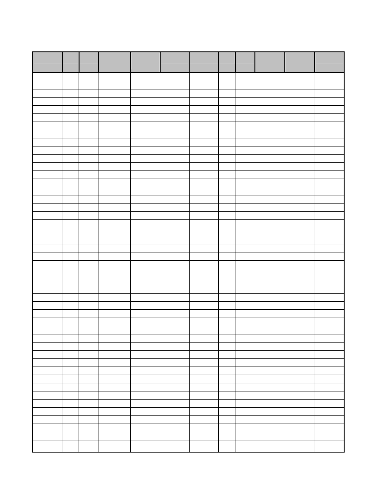
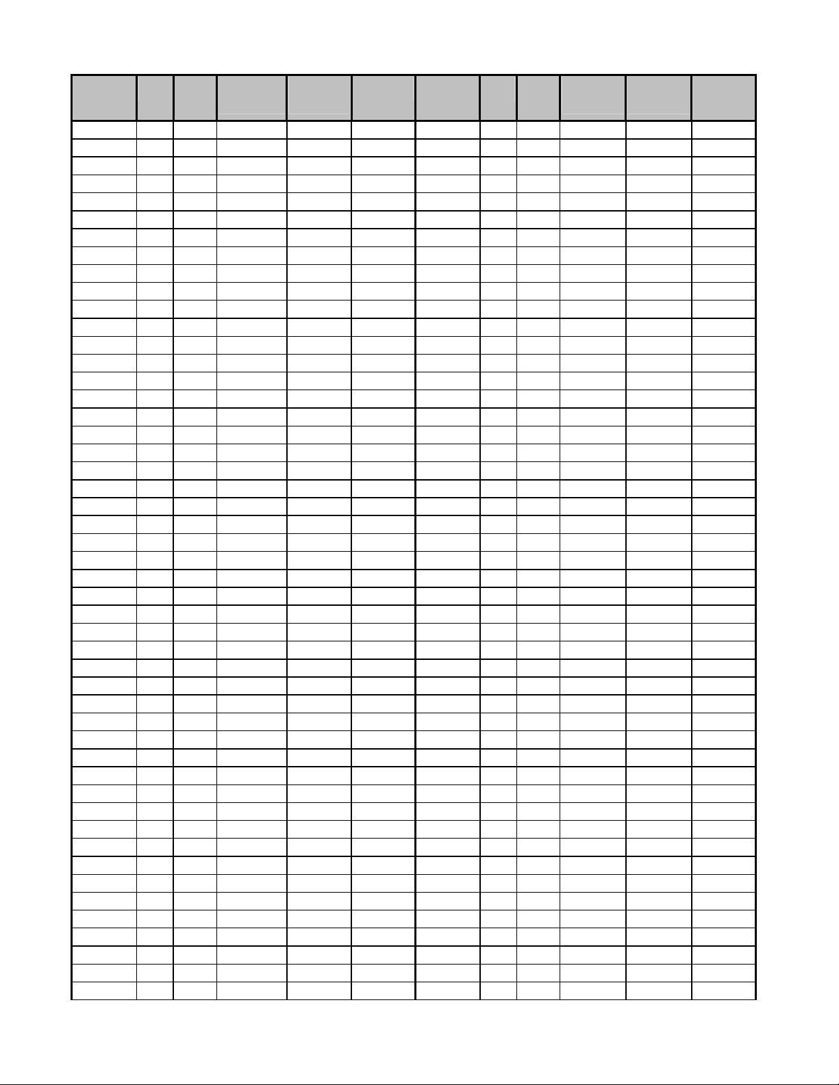
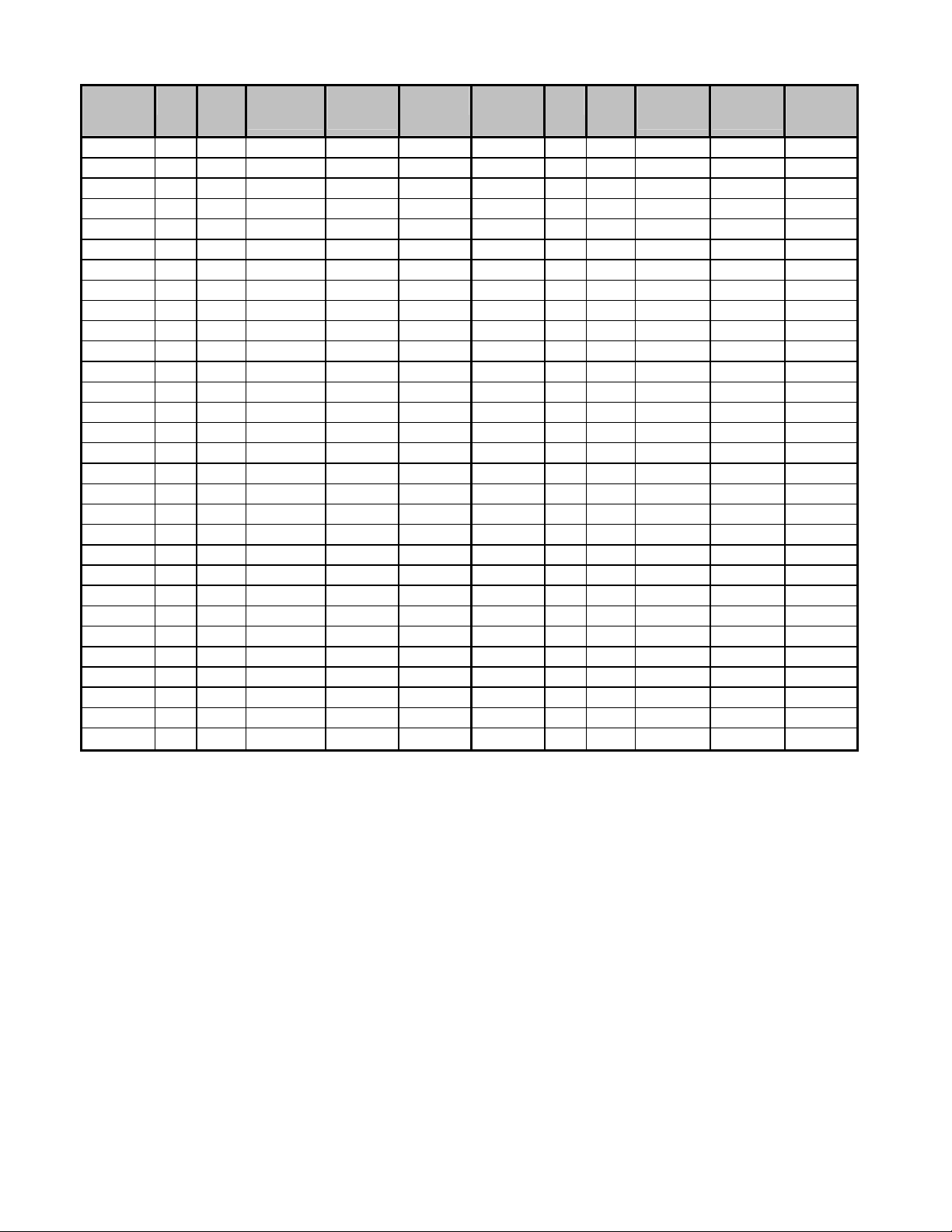
TABLE 2: CONDENSER AND HEAT RECLAIM
Condenser
ID
CCD02 1 1 1.8 5.8 190 CL8053 2 2 47 153 1882
CCD03 1 1 2.7 8.7 201 CL8054 1 4 46 150 2019
CCD04 1 1 3.5 12 210 CL8055 2 3 34 112 2323
CH8010 1 1 5.8 19 515 CL8059 1 5 43 140 2403
CH8013 1 1 8.8 29 592 CL8068 1 5 57 187 2475
CH8015 1 1 12 38 641 CL8071 2 3 52 169 2508
CH8020 1 2 12 38 985 CL8081 2 3 69 225 2664
CH8026 1 2 17 57 1063 CL8094 2 4 68 224 3029
CH8029 1 2 23 76 1117 CL8108 2 4 91 299 3338
CH8038 1 3 26 85 1460 CL8118 2 5 85 280 4198
CH8040 2 2 23 75 1625 CL8135 2 5 114 373 4560
CH8044 1 3 34 112 1570 CL8141 2 6 164 553 5292
CH8051 2 2 35 115 1792 CL8162 2 6 218 717 5642
CH8052 1 4 34 112 1875 CLD009 1 1 5.8 19 515
CH8058 2 2 47 153 1882 CLD010 1 1 5.8 19 525
CH8059 1 4 46 150 2019 CLD012 1 1 8.8 29 592
CH8060 2 3 34 112 2323 CLD013 1 1 8.8 29 602
CH8065 1 5 43 140 2403 CLD014 1 1 12 38 641
CH8074 1 5 57 187 2475 CLD015 1 1 12 38 654
CH8078 2 3 52 169 2508 CLD018 1 2 12 38 985
CH8088 2 3 69 225 2664 CLD021 1 2 12 38 1005
CH8104 2 4 68 224 3029 CLD023 1 2 17 57 1063
CH8118 2 4 91 299 3338 CLD026 1 2 17 57 1091
CH8130 2 5 85 280 4198 CLD028 1 2 23 76 1117
CH8147 2 5 114 373 4560 CLD030 1 2 23 76 1159
CH8156 2 6 197 664 5292 CLD035 1 3 26 85 1460
CH8177 2 6 262 860 5642 CLD040 1 3 26 85 1490
CHD010 1 1 5.8 19 515 CLD042 2 2 23 75 1625
CHD012 1 1 5.8 19 525 CLD043 1 3 34 112 1570
CHD013 1 1 8.8 29 592 CLD045 1 3 34 112 1609
CHD014 1 1 8.8 29 602 CLD049 2 2 35 115 1792
CHD015 1 1 12 38 641 CLD050 1 4 34 112 1875
CHD016 1 1 12 38 654 CLD053 2 2 35 115 1781
CHD020 1 2 12 38 985 CLD054 1 4 34 112 1915
CHD024 1 2 12 38 1005 CLD056 2 2 47 153 1882
CHD026 1 2 17 57 1063 CLD057 1 4 46 150 2019
CHD029 1 2 17 57 1091 CLD060 2 2 47 153 1934
CHD030 1 2 23 76 1117 CLD061 1 4 46 150 2071
CHD032 1 2 23 76 1159 CLD063 2 3 34 112 2323
CHD040 1 3 26 85 1460 CLD066 1 5 43 140 2403
CHD044 1 3 26 85 1490 CLD070 1 5 57 187 2475
CHD045 1 3 23 75 1625 CLD075 1 5 57 187 2540
CHD048 1 3 34 112 1570 CLD080 2 3 52 169 2508
CHD049 2 2 34 112 1609 CLD085 2 3 69 225 2664
CHD055 2 2 35 115 1792 CLD090 2 3 69 225 2742
Width
Length
(fan)
(fan)
Refrigerant
Charge
Summer (lb)
Refrigerant
Charge
Winter (lb)
Shipping
Weight (lb)
Condenser
ID
Width
(fan)
Length
(fan)
Refrigerant
Charge
Summer (lb)
Refrigerant
Charge
Winter (lb)
Shipping
Weight (lb)
7
Page 8
Condenser
ID
CHD056 1 4 34 112 1875 CLD099 2 4 68 224 3029
CHD059 2 2 35 115 1781 CLD106 2 4 68 224 3129
CHD060 1 4 34 112 1915 CLD113 2 4 91 299 3338
CHD061 2 2 47 153 1882 CLD120 2 4 91 229 3442
CHD062 1 4 46 150 2019 CLD124 2 5 85 280 4198
CHD063 2 2 47 153 1934 CLD132 2 5 85 280 4298
CHD064 1 4 46 150 2071 CLD142 2 5 114 373 4560
CHD073 2 3 34 112 2323 CLD150 2 5 114 373 4690
CHD074 1 5 43 140 2403 CLD159 2 6 164 553 5292
CHD077 1 5 57 187 2475 CLD170 2 6 218 717 5642
CHD079 1 5 57 187 2540 CLD180 2 6 218 717 5798
CHD089 2 3 52 169 2508 CMD05 1 1 3.3 11 308
CHD092 2 3 69 225 2664 CMD07 1 1 4.9 16 335
CHD096 2 3 69 225 2742 CMD08 1 1 6.5 22 350
CHD110 2 4 68 224 3029 CMD09 1 2 6.3 21 489
CHD118 2 4 68 224 3129 CMD11 1 2 9.5 31 518
CHD123 2 4 91 299 3338 CMD12 1 2 9.5 31 532
CHD127 2 4 91 229 3442 CMD13 1 2 13 42 544
CHD138 2 5 85 280 4198 CMD14 1 2 13 42 566
CHD148 2 5 85 280 4298 CMD18 1 3 14 47 727
CHD153 2 5 114 373 4560 CMD20 1 3 14 47 741
CHD159 2 5 114 373 4690 CMD21 1 3 19 62 767
CHD177 2 6 164 553 5292 CMD23 1 3 19 62 789
CHD184 2 6 218 717 5642 CQD008 1 1 5.8 19 525
CHD191 2 6 218 717 5798 CQD009 1 1 5.8 19 535
CID010 1 1 5.8 19 515 CQD010 1 1 8.8 29 602
CID011 1 1 5.8 19 525 CQD011 1 1 8.8 29 612
CID013 1 1 8.8 29 592 CQD012 1 1 12 38 651
CID014 1 1 8.8 29 602 CQD013 1 1 12 38 664
CID016 1 1 12 38 641 CQD016 1 2 12 38 1085
CID017 1 1 12 38 654 CQD019 1 2 12 38 1025
CID020 1 2 12 38 985 CQD021 1 2 17 57 1083
CID023 1 2 12 38 1005 CQD022 1 2 17 57 1111
CID025 1 2 17 57 1063 CQD023 1 2 23 76 1137
CID029 1 2 17 57 1091 CQD024 1 2 23 76 1179
CID031 1 2 23 76 1117 CQD031 1 3 26 85 1490
CID034 1 2 23 76 1159 CQD034 1 3 26 85 1520
CID039 1 3 26 85 1460 CQD035 1 3 34 112 1600
CID044 1 3 26 85 1490 CQD036 1 3 34 112 1639
CID046 2 2 23 75 1625 CQD041 2 2 35 115 1832
CID049 1 3 34 112 1570 CQD042 1 4 34 112 1915
CID051 1 3 34 112 1609 CQD044 2 2 35 115 1821
CID054 2 2 35 115 1792 CQD045 1 4 34 112 1955
CID055 1 4 34 112 1875 CQD046 2 2 47 153 1922
CID058 2 2 35 115 1781 CQD047 1 4 46 150 2059
CID059 1 4 34 112 1915 CQD048 2 2 47 153 1974
CID064 2 2 47 153 1882 CQD049 1 4 46 150 2111
CID065 1 4 46 150 2019 CQD057 1 5 43 140 2453
CID068 2 2 47 153 1934 CQD058 1 5 57 187 2525
Width
(fan)
Length
(fan)
Refrigerant
Charge
Summer (lb)
Refrigerant
Charge
Winter (lb)
Shipping
Weight (lb)
Condenser
ID
Width
(fan)
Length
(fan)
Refrigerant
Charge
Summer (lb)
Refrigerant
Charge
Winter (lb)
Shipping
Weight (lb)
8
Page 9
Condenser
ID
CID069 1 4 46 150 2071 CQD061 1 5 57 187 2590
CID070 2 3 34 112 2323 CQD069 2 3 52 169 2568
CID073 1 5 43 140 2403 CQD070 2 3 69 225 2724
CID079 1 5 57 187 2475 CQD072 2 3 69 225 2800
CID085 2 5 57 187 2540 CQD083 2 4 68 224 3109
CID088 2 3 52 169 2508 CQD091 2 4 68 224 3209
CID095 2 3 69 225 2664 CQD093 2 4 91 299 3418
CID101 2 3 69 225 2742 CQD096 2 4 91 299 3522
CID112 2 4 68 224 3029 CQD104 2 5 85 280 4298
CID119 2 4 68 224 3129 CQD114 2 5 85 280 4398
CID129 2 4 91 299 3338 CQD116 2 5 114 373 4660
CID137 2 4 91 229 3442 CQD121 2 5 114 373 4790
CID141 2 5 85 280 4198 CQD137 2 6 164 553 5412
CID149 2 5 85 280 4298 CQD140 2 6 218 717 5762
CID162 2 5 114 373 4560 CQD145 2 6 218 717 5918
CID171 2 5 114 373 4690 HCD02 1 1 0.6 0.6 190
CID178 2 6 164 553 5292 HCD03 1 1 0.9 0.9 201
CID194 2 6 218 717 5642 HCD04 1 1 1.2 1.2 210
CID205 2 6 218 717 5798 HMD05 1 1 1.1 1.1 308
CL8009 1 1 5.8 19 515 HMD07 1 1 1.6 1.6 335
CL8012 1 1 8.8 29 592 HMD08 1 1 2.1 2.1 350
CL8014 1 1 12 38 641 HMD09 1 2 2.1 2.1 489
CL8018 1 2 12 38 985 HMD11 1 2 3.1 3.1 518
CL8024 1 2 17 57 1063 HMD12 1 2 3.1 3.1 532
CL8027 1 2 23 76 1117 HMD13 1 2 4.3 4.3 544
CL8035 1 3 26 85 1460 HMD14 1 2 4.3 4.3 566
CL8036 2 2 23 75 1625 HMD18 1 3 4.6 4.6 727
CL8041 1 3 34 112 1570 HMD20 1 3 4.6 4.6 741
CL8047 2 2 35 115 1792 HMD21 1 3 6.3 6.3 767
CL8048 1 4 34 112 1875 HMD23 1 3 6.3 6.3 789
Width
(fan)
Length
(fan)
Refrigerant
Charge
Summer (lb)
Refrigerant
Charge
Winter (lb)
Shipping
Weight (lb)
Condenser
ID
Width
(fan)
Length
(fan)
Refrigerant
Charge
Summer (lb)
Refrigerant
Charge
Winter (lb)
Shipping
Weight (lb)
9
Page 10

Refrigerant
Charge
Condenser
ID
CCR02 1 1 2 6 190 CMR16 1 2 13 42 566
CCR03 1 1 3 9 201 CMR18 1 3 10 33 727
CCR04 1 1 4 12 210 CMR22 1 3 15 48 741
CNW011 1 1 6 19 520 CMR25 1 3 20 66 789
CNW014 1 1 9 29 597 CMR30 2 4 19 62 1064
CNW017 1 1 12 38 648 CMR33 2 4 26 84 1132
CNW021 1 2 12 38 612 CMR36 2 6 20 66 1454
CNW028 1 2 23 76 995 CMR45 2 6 29 96 1482
CNW033 1 2 23 76 1138 CMR49 2 6 39 132 1578
CNW042 1 3 26 85 1475 CVR012L 1 1 6 19 565
CNW050 1 3 34 112 1590 CVR014L 1 1 6 19 575
CNW056 1 4 34 112 1796 CVR016L 1 1 9 29 642
CNW057 2 4 35 115 1900 CVR017L 1 1 9 29 652
CNW066 1 4 46 150 1908 CVR018L 1 1 12 38 691
CNW067 2 4 47 153 2045 CVR019L 1 1 12 38 704
CNW077 1 5 68 230 2361 CVR025L 1 2 12 38 1085
CNW089 1 5 90 298 2507 CVR028L 1 2 12 38 1105
CNW085 2 6 52 170 2468 CVR031L 1 2 17 57 1163
CNW092 1 6 82 276 2768 CVR034L 1 2 17 57 1191
CNW100 2 6 68 224 2703 CVR035L 1 2 23 76 1217
CNW107 1 6 109 359 3003 CVR037L 1 2 23 76 1259
CNW113 2 4 68 224 3079 CVR047L 1 3 26 85 1610
CNW133 2 4 92 300 3390 CVR051L 1 3 26 85 1640
CNW154 2 5 136 460 4248 CVR053L 1 3 34 112 1720
CNW179 2 5 180 596 4625 CVR056L 1 3 34 112 1759
CNW185 2 6 164 552 5242 CVR061L 1 4 34 112 2075
CNW215 2 6 218 718 5716 CVR062L 2 4 35 115 1910
CNR012 1 1 6 19 515 CVR067L 1 4 34 112 2115
CNR014 1 1 6 19 525 CVR068L 2 4 35 115 1992
CNR016 1 1 9 29 592 CVR070L 1 4 46 150 2219
CNR017 1 1 9 29 602 CVR071L 2 4 47 153 2082
CNR018 1 1 12 38 641 CVR074L 1 4 46 150 2271
CNR019 1 1 12 38 654 CVR075L 2 4 47 153 2134
CNR024 1 2 12 38 985 CVR083L 2 6 36 114 2623
CNR027 1 2 12 38 1005 CVR084L 1 5 68 230 2653
CNR032 1 2 17 57 1063 CVR089L 1 5 68 230 2653
CNR035 1 2 17 57 1091 CVR092L 1 5 90 298 2725
CNR036 1 2 23 76 1117 CVR096L 1 5 90 298 2790
CNR039 1 2 23 76 1159 CVR094L 2 6 52 170 2730
CNR048 1 3 26 85 1460 CVR099L 1 6 82 276 3000
CNR052 1 3 26 85 1490 CVR101L 2 6 52 170 2808
CNR054 1 3 34 112 1570 CVR105L 1 6 82 276 3108
CNR058 1 3 34 112 1609 CVR106L 2 6 68 224 2964
Width
(fan)
Length
(fan)
Summer
(lb)
Refrigerant
Charge
Winter (lb)
Shipping
Weight
(lb)
Condenser
ID
Width
(fan)
Length
(fan)
Refrigerant
Charge
Summer
(lb)
Refrigerant
Charge
Winter (lb)
Shipping
Weight
(lb)
10
Page 11

Refrigerant
Charge
Condenser
ID
CNR063 1 4 34 112 1875 CVR111L 1 6 109 359 3264
CNR064 2 4 35 115 1792 CVR112L 2 6 68 224 3042
CNR069 1 4 34 112 1915 CVR116L 1 6 109 359 3342
CNR070 2 4 35 115 1781 CVR125L 2 4 68 224 3429
CNR072 1 4 46 150 2019 CVR135L 2 4 68 224 3529
CNR073 2 4 47 153 1934 CVR141L 2 4 92 300 3738
CNR077 1 4 46 150 2071 CVR149L 2 4 92 300 3842
CNR078 2 4 47 153 2071 CVR165L 2 5 136 460 4698
CNR082 2 6 36 114 2323 CVR177L 2 5 136 460 4798
CNR085 1 5 68 230 2338 CVR184L 2 5 180 596 5060
CNR092 1 5 68 230 2403 CVR192L 2 5 180 596 5190
CNR096 1 5 90 298 2475 CVR200L 2 6 164 552 5736
CNR101 1 5 90 298 2540 CVR212L 2 6 164 552 5892
CNR095 2 6 52 170 2430 CVR221L 2 6 218 718 6242
CNR102 1 6 82 276 2730 CVR231L 2 6 218 718 6398
CNR104 2 6 52 170 2508 CVR012 1 1 6 19 565
CNR111 1 6 82 276 2808 CVR014 1 1 6 19 575
CNR109 2 6 68 224 2664 CVR016 1 1 9 29 642
CNR116 1 6 109 359 2964 CVR017 1 1 9 29 652
CNR115 2 6 68 224 2742 CVR018 1 1 12 38 691
CNR121 1 6 109 359 3000 CVR019 1 1 12 38 704
CNR127 2 4 68 224 3029 CVR025 1 2 12 38 1085
CNR139 2 4 68 224 3129 CVR028 1 2 12 38 1105
CNR145 2 4 92 300 3338 CVR031 1 2 17 57 1163
CNR154 2 4 92 300 3442 CVR034 1 2 17 57 1191
CNR171 2 5 136 460 4198 CVR035 1 2 23 76 1217
CNR185 2 5 136 460 4298 CVR037 1 2 23 76 1259
CNR193 2 5 180 596 4560 CVR047 1 3 26 85 1610
CNR202 2 5 180 596 4690 CVR051 1 3 26 85 1640
CNR205 2 6 164 552 5136 CVR053 1 3 34 112 1720
CNR222 2 6 164 552 5292 CVR056 1 3 34 112 1759
CNR231 2 6 218 718 5642 CVR061 1 4 34 112 2075
CNR243 2 6 218 718 5798 CVR062 2 4 35 115 1910
CNX015 1 1 7 24 550 CVR067 1 4 34 112 2115
CNX019 1 1 11 35 600 CVR068 2 4 35 115 1992
CNX021 1 1 15 47 650 CVR070 1 4 46 150 2219
CNX030 1 2 14 46 850 CVR071 2 4 47 153 2082
CNX038 1 2 22 69 900 CVR074 1 4 46 150 2271
CNX043 1 2 29 92 950 CVR075 2 4 47 153 2134
CNX057 1 3 32 103 1300 CVR083 2 6 36 114 2623
CNX064 1 3 43 137 1425 CVR084 1 5 68 230 2653
CNX076 1 4 43 136 1725 CVR089 1 5 68 230 2653
CNX086 1 4 57 182 1900 CVR092 1 5 90 298 2725
Width
(fan)
Length
(fan)
Summer
(lb)
Refrigerant
Charge
Winter (lb)
Shipping
Weight
(lb)
Condenser
ID
Width
(fan)
Length
(fan)
Refrigerant
Charge
Summer
(lb)
Refrigerant
Charge
Winter (lb)
Shipping
Weight
(lb)
11
Page 12

Refrigerant
Charge
Condenser
ID
CNX096 1 5 53 170 2150 CVR096 1 5 90 298 2790
CNX108 1 5 71 227 2375 CVR094 2 6 52 170 2730
CNX123 1 6 101 323 2575 CVR099 1 6 82 276 3000
CNX135 1 6 134 430 2850 CVR101 2 6 52 170 2808
CNX144 1 7 117 376 3012 CVR105 1 6 82 276 3108
CNX158 1 7 157 501 3362 CVR106 2 6 68 224 2964
CNX164 1 4 134 429 3450 CVR111 1 6 109 359 3264
CNX181 1 4 179 572 3800 CVR112 2 6 68 224 3042
CNX061 2 4 29 92 1000 CVR116 1 6 109 359 3342
CNX077 2 4 43 138 1600 CVR125 2 4 68 224 3429
CNX087 2 4 58 184 2000 CVR135 2 4 68 224 3529
CNX115 2 6 64 205 2600 CVR141 2 4 92 300 3738
CNX129 2 6 86 274 3000 CVR149 2 4 92 300 3842
CNX154 2 4 85 273 3600 CVR165 2 5 136 460 4698
CNX172 2 4 114 363 4000 CVR177 2 5 136 460 4798
CNX192 2 5 106 340 4500 CVR184 2 5 180 596 5060
CNX215 2 5 142 453 5000 CVR192 2 5 180 596 5190
CNX247 2 6 202 645 5400 CVR200 2 6 164 552 5736
CNX271 2 6 269 860 6000 CVR212 2 6 164 552 5892
CNX288 2 7 235 752 6400 CVR221 2 6 218 718 6242
CNX316 2 7 313 1002 7000 CVR231 2 6 218 718 6398
CNX329 2 8 268 858 7400 CVW011 1 1 6 19 570
CNX362 2 8 358 1145 8000 CVW014 1 1 9 29 647
CLW009 1 1 6 19 515 CVW016 1 1 12 38 698
CLW012 1 1 9 29 592 CVW021 1 2 12 38 1012
CLW014 1 1 12 38 641 CVW028 1 2 23 76 1095
CLW019 1 2 12 38 985 CVW033 1 2 23 76 1238
CLW024 1 2 23 76 1063 CVW042 1 3 26 85 1625
CLW028 1 2 23 76 1117 CVW049 1 3 34 112 1740
CLW036 1 3 26 85 1460 CVW055 1 4 34 112 2100
CLW042 1 3 34 112 1570 CVW056 2 4 35 115 1996
CLW048 1 4 34 112 1875 CVW064 1 4 46 150 2245
CLW049 2 4 35 115 1792 CVW065 2 4 47 153 2108
CLW056 1 4 46 150 2019 CVW070 1 5 68 230 2611
CLW057 2 4 47 153 1882 CVW081 1 5 90 298 2757
CLW066 1 5 68 230 2403 CVW084 2 6 52 170 2768
CLW075 1 5 90 298 2475 CVW090 1 6 82 276 3068
CLW073 2 6 52 170 2508 CVW098 2 6 68 224 3003
CLW079 1 6 82 276 2808 CVW104 1 6 109 359 3303
CLW085 2 6 68 224 2664 CVW112 2 4 68 224 3479
CLW090 1 6 109 359 2964 CVW130 2 4 92 300 3790
CLW097 2 4 68 224 3029 CVW140 2 5 136 460 4748
CLW113 2 4 92 300 3338 CVW163 2 5 180 596 5125
Width
(fan)
Length
(fan)
Summer
(lb)
Refrigerant
Charge
Winter (lb)
Shipping
Weight
(lb)
Condenser
ID
Width
(fan)
Length
(fan)
Refrigerant
Charge
Summer
(lb)
Refrigerant
Charge
Winter (lb)
Shipping
Weight
(lb)
12
Page 13

Refrigerant
Charge
Condenser
ID
CLW131 2 5 136 460 4198 CVW167 2 6 164 552 5842
CLW151 2 5 180 596 4560 CVW195 2 6 218 718 6316
CLW158 2 6 164 552 5292 CVW011L 1 1 6 19 570
CLW181 2 6 218 718 5642 CVW014L 1 1 9 29 647
CLR010 1 1 6 19 515 CVW016L 1 1 12 38 698
CLR011 1 1 6 19 525 CVW021L 1 2 12 38 1012
CLR013 1 1 9 29 592 CVW028L 1 2 23 76 1095
CLR014 1 1 9 29 602 CVW033L 1 2 23 76 1238
CLR015 1 1 12 38 641 CVW042L 1 3 26 85 1625
CLR016 1 1 12 38 654 CVW049L 1 3 34 112 1740
CLR021 1 2 12 38 985 CVW055L 1 4 34 112 2100
CLR023 1 2 12 38 1005 CVW056L 2 4 35 115 1996
CLR027 1 2 17 57 1063 CVW064L 1 4 46 150 2245
CLR029 1 2 17 57 1091 CVW065L 2 4 47 153 2108
CLR031 1 2 23 76 1117 CVW070L 1 5 68 230 2611
CLR032 1 2 23 76 1159 CVW081L 1 5 90 298 2757
CLR040 1 3 26 85 1460 CVW084L 2 6 52 170 2768
CLR044 1 3 26 85 1490 CVW090L 1 6 82 276 3068
CLR046 1 3 34 112 1570 CVW098L 2 6 68 224 3003
CLR049 1 3 34 112 1609 CVW104L 1 6 109 359 3303
CLR053 1 4 34 112 1875 CVW112L 2 4 68 224 3479
CLR054 2 4 35 115 1792 CVW130L 2 4 92 300 3790
CLR057 1 4 34 112 1915 CVW140L 2 5 136 460 4748
CLR058 2 4 35 115 1781 CVW163L 2 5 180 596 5125
CLR060 1 4 46 150 2019 CVW167L 2 6 164 552 5842
CLR062 2 4 47 153 1882 CVW195L 2 6 218 718 6316
CLR064 1 4 46 150 2071 CVX015 1 1 7 24 600
CLR065 2 4 47 153 1934 CVX019 1 1 11 35 650
CLR069 2 6 36 114 2323 CVX021 1 1 15 47 700
CLR072 1 5 68 230 2338 CVX031 1 2 14 46 950
CLR077 1 5 68 230 2403 CVX038 1 2 22 69 1000
CLR081 1 5 90 298 2475 CVX042 1 2 29 92 1050
CLR084 1 5 90 298 2540 CVX057 1 3 32 103 1450
CLR080 2 6 52 170 2430 CVX063 1 3 43 137 1575
CLR086 1 6 82 276 2730 CVX076 1 4 43 136 1925
CLR087 2 6 52 170 2508 CVX084 1 4 57 182 2100
CLR093 1 6 82 276 2808 CVX096 1 5 53 170 2400
CLR092 2 6 68 224 2664 CVX106 1 5 71 227 2625
CLR096 1 6 109 359 2964 CVX122 1 6 101 323 2875
CLR097 2 6 68 224 2742 CVX131 1 6 134 430 3150
CLR101 1 6 109 359 3042 CVX142 1 7 117 376 3362
CLR107 2 4 68 224 3029 CVX153 1 7 157 501 3712
CLR117 2 4 68 224 3129 CVX163 1 4 134 429 3850
Width
(fan)
Length
(fan)
Summer
(lb)
Refrigerant
Charge
Winter (lb)
Shipping
Weight
(lb)
Condenser
ID
Width
(fan)
Length
(fan)
Refrigerant
Charge
Summer
(lb)
Refrigerant
Charge
Winter (lb)
Shipping
Weight
(lb)
13
Page 14

Refrigerant
Charge
Condenser
ID
CLW131 2 5 136 460 4198 CVW167 2 6 164 552 5842
CLW151 2 5 180 596 4560 CVW195 2 6 218 718 6316
CLW158 2 6 164 552 5292 CVW011L 1 1 6 19 570
CLW181 2 6 218 718 5642 CVW014L 1 1 9 29 647
CLR010 1 1 6 19 515 CVW016L 1 1 12 38 698
CLR011 1 1 6 19 525 CVW021L 1 2 12 38 1012
CLR013 1 1 9 29 592 CVW028L 1 2 23 76 1095
CLR014 1 1 9 29 602 CVW033L 1 2 23 76 1238
CLR015 1 1 12 38 641 CVW042L 1 3 26 85 1625
CLR016 1 1 12 38 654 CVW049L 1 3 34 112 1740
CLR021 1 2 12 38 985 CVW055L 1 4 34 112 2100
CLR023 1 2 12 38 1005 CVW056L 2 4 35 115 1996
CLR027 1 2 17 57 1063 CVW064L 1 4 46 150 2245
CLR029 1 2 17 57 1091 CVW065L 2 4 47 153 2108
CLR031 1 2 23 76 1117 CVW070L 1 5 68 230 2611
CLR032 1 2 23 76 1159 CVW081L 1 5 90 298 2757
CLR040 1 3 26 85 1460 CVW084L 2 6 52 170 2768
CLR044 1 3 26 85 1490 CVW090L 1 6 82 276 3068
CLR046 1 3 34 112 1570 CVW098L 2 6 68 224 3003
CLR049 1 3 34 112 1609 CVW104L 1 6 109 359 3303
CLR053 1 4 34 112 1875 CVW112L 2 4 68 224 3479
CLR054 2 4 35 115 1792 CVW130L 2 4 92 300 3790
CLR057 1 4 34 112 1915 CVW140L 2 5 136 460 4748
CLR058 2 4 35 115 1781 CVW163L 2 5 180 596 5125
CLR060 1 4 46 150 2019 CVW167L 2 6 164 552 5842
CLR062 2 4 47 153 1882 CVW195L 2 6 218 718 6316
CLR064 1 4 46 150 2071 CVX015 1 1 7 24 600
CLR065 2 4 47 153 1934 CVX019 1 1 11 35 650
CLR069 2 6 36 114 2323 CVX021 1 1 15 47 700
CLR072 1 5 68 230 2338 CVX031 1 2 14 46 950
CLR077 1 5 68 230 2403 CVX038 1 2 22 69 1000
CLR081 1 5 90 298 2475 CVX042 1 2 29 92 1050
CLR084 1 5 90 298 2540 CVX057 1 3 32 103 1450
CLR080 2 6 52 170 2430 CVX063 1 3 43 137 1575
CLR086 1 6 82 276 2730 CVX076 1 4 43 136 1925
CLR087 2 6 52 170 2508 CVX084 1 4 57 182 2100
CLR093 1 6 82 276 2808 CVX096 1 5 53 170 2400
CLR092 2 6 68 224 2664 CVX106 1 5 71 227 2625
CLR096 1 6 109 359 2964 CVX122 1 6 101 323 2875
CLR097 2 6 68 224 2742 CVX131 1 6 134 430 3150
CLR101 1 6 109 359 3042 CVX142 1 7 117 376 3362
CLR107 2 4 68 224 3029 CVX153 1 7 157 501 3712
CLR117 2 4 68 224 3129 CVX163 1 4 134 429 3850
Width
(fan)
Length
(fan)
Summer
(lb)
Refrigerant
Charge
Winter (lb)
Shipping
Weight
(lb)
Condenser
ID
Width
(fan)
Length
(fan)
Refrigerant
Charge
Summer
(lb)
Refrigerant
Charge
Winter (lb)
Shipping
Weight
(lb)
14
Page 15

Refrigerant
Charge
Condenser
ID
CLR122 2 4 92 300 3338 CVX175 1 4 179 572 4200
CLR130 2 4 92 300 3442 CVX062 2 4 29 92 1100
CLR144 2 5 136 460 4198 CVX077 2 4 43 138 1700
CLR155 2 5 136 460 4298 CVX085 2 4 58 184 2100
CLR161 2 5 180 596 4560 CVX115 2 6 64 205 2750
CLR167 2 5 180 596 4690 CVX127 2 6 86 274 3150
CLR173 2 6 164 552 5292 CVX154 2 4 85 273 3800
CLR186 2 6 164 552 5642 CVX170 2 4 114 363 4200
CLR193 2 6 218 718 5798 CVX192 2 5 106 340 4750
CLR202 2 6 218 718 5798 CVX212 2 5 142 453 5250
CLX013 1 1 7 24 550 CVX245 2 6 202 645 5700
CLX016 1 1 11 35 600 CVX262 2 6 269 860 6300
CLX018 1 1 15 47 650 CVX285 2 7 235 752 6750
CLX026 1 2 14 46 850 CVX306 2 7 313 1002 7350
CLX032 1 2 22 69 900 CVX326 2 8 268 858 7800
CLX036 1 2 29 92 950 CVX350 2 8 358 1145 8400
CLX049 1 3 32 103 1300 CVX015L 1 1 7 24 600
CLX054 1 3 43 137 1425 CVX019L 1 1 11 35 650
CLX064 1 4 43 136 1725 CVX021L 1 1 15 47 700
CLX071 1 4 57 182 1900 CVX031L 1 2 14 46 950
CLX081 1 5 53 170 2150 CVX038L 1 2 22 69 1000
CLX089 1 5 71 227 2375 CVX042L 1 2 29 92 1050
CLX103 1 6 101 323 2575 CVX057L 1 3 32 103 1450
CLX111 1 6 134 430 2850 CVX063L 1 3 43 137 1575
CLX120 1 7 117 376 3012 CVX076L 1 4 43 136 1925
CLX129 1 7 157 501 3362 CVX084L 1 4 57 182 2100
CLX138 1 4 134 429 3450 CVX096L 1 5 53 170 2400
CLX148 1 4 179 572 3800 CVX106L 1 5 71 227 2625
CLX053 2 4 29 92 1000 CVX122L 1 6 101 323 2875
CLX065 2 4 43 138 1600 CVX131L 1 6 134 430 3150
CLX072 2 4 58 184 2000 CVX142L 1 7 117 376 3362
CLX097 2 6 64 205 2600 CVX153L 1 7 157 501 3712
CLX107 2 6 86 274 3000 CVX163L 1 4 134 429 3850
CLX130 2 4 85 273 3600 CVX175L 1 4 179 572 4200
CLX143 2 4 114 363 4000 CVX062L 2 4 29 92 1100
CLX162 2 5 106 340 4500 CVX077L 2 4 43 138 1700
CLX178 2 5 142 453 5000 CVX085L 2 4 58 184 2100
CLX207 2 6 202 645 5400 CVX115L 2 6 64 205 2750
CLX222 2 6 269 860 6000 CVX127L 2 6 86 274 3150
CLX241 2 7 235 752 6400 CVX154L 2 4 85 273 3800
CLX259 2 7 313 1002 7000 CVX170L 2 4 114 363 4200
CLX275 2 8 268 858 7400 CVX192L 2 5 106 340 4750
CLX296 2 8 358 1145 8000 CVX212L 2 5 142 453 5250
Width
(fan)
Length
(fan)
Summer
(lb)
Refrigerant
Charge
Winter (lb)
Shipping
Weight
(lb)
Condenser
ID
Width
(fan)
Length
(fan)
Refrigerant
Charge
Summer
(lb)
Refrigerant
Charge
Winter (lb)
Shipping
Weight
(lb)
15
Page 16

Refrigerant
Charge
Condenser
ID
CMR06 1 1 3 11 308 CVX245L 2 6 202 645 5700
CMR07 1 1 5 16 335 CVX262L 2 6 269 860 6300
CMR08 1 1 7 22 350 CVX285L 2 7 235 752 6750
CMR12 1 2 6 21 489 CVX306L 2 7 313 1002 7350
CMR15 1 2 10 31 532 CVX326L 2 8 268 858 7800
CVX350L 2 8 358 1145 8400
Width
(fan)
Length
(fan)
Summer
(lb)
Refrigerant
Charge
Winter (lb)
Shipping
Weight
(lb)
Condenser
ID
Width
(fan)
Length
(fan)
Refrigerant
Charge
Summer
(lb)
Refrigerant
Charge
Winter (lb)
Shipping
Weight
(lb)
16
Page 17

Fig. #1: Standard Legs
17
Page 18

18
Page 19

19
Page 20

Fig. #2 : Extended Legs
20
Page 21

Fig #3: 2 fans
21
Page 22

Fig # 4: 1 fan
22
Page 23

Table #3
Fan Motor
WITH ANY
Condenser Fan Alignment Ambient Control Temperature Setting (°F)
Temperature Control ------ T1 T2 T3 T4 T5 T6 T7
Single Wide Units M1 M2 M3 M4 M5 M6
Number
Difference
Fan On 60
Fan Off 40
Difference
Fan On 55 65
Fan Off 45 50
Difference
Fan On 55 60 70
Fan Off 45 55 65
Difference
Fan On 55 60 70 75
Fan Off 45 55 65 70
Difference
Fan On 55 60 65 70 80
Fan Off 45 55 60 75 75
Difference
Fan On 55 60 65 70 75 80
Fan Off 45 55 60 65 70 75
Difference
Fan On 50 55 60 65 70 75 80
Fan Off
Double Wide Units
M1
M2
20
10 15
10 5 5
10 5 5 5
10 5 5 5 5
10 5 5 5 5 5
5 5 5 5 5 5 5
FAN (S)
RUNS
COM-
PRESSOR
M3
M4
45 50 55 60 65 70 75
M5
M6
M7
M8
M9
M10
M11
M12
M13
M14
M15
M16
23
Page 24

Table #4
Fan Motor
WITH ANY
Condenser Fan Alignment Pressure Control
Pressure Settings (PSIG) (R-22)
Pressure Control ------ P1 P2 P3 P4 P5 P6 P7
Single Wide Units M1 M2 M3 M4 M5 M6
Number
Difference
Fan On 200
Fan Off 160
Difference
Fan On 200 210
Fan Off 160 170
Difference
Fan On 200 205 215
Fan Off 160 165 175
Difference
Fan On 200 205 210 220
Fan Off 160 165 170 180
Difference
Fan On 200 205 210 215 225
Fan Off 160 165 170 175 185
Difference
Fan On 200 205 210 215 220 225
Fan Off 160 165 170 175 180 185
Difference
Fan On 200 205 210 215 220 225 230
Fan Off
Double Wide Units
M1
M2
40
40 40
40 40 40
40 40 40 40
40 40 40 40 40
40 40 40 40 40 40
40 40 40 40 40 40 40
FAN (S)
RUNS
COM-
PRESSOR
M3
M4
160 165 170 175 180 185 190
M5
M6
M7
M8
M9
M10
M11
M12
M13
M14
M15
M16
24
Page 25

Fan Motor
WITH ANY
Table #5
Condenser Fan Alignment Pressure Control
Pressure Settings (PSIG) (R-404A, R-507)
Pressure Control ------ P1 P2 P3 P4 P5 P6 P7
Single Wide Units M1 M2 M3 M4 M5 M6
Number
Difference
Fan On 240
Fan Off 200
Difference
Fan On 240 250
Fan Off 200 210
Difference
Fan On 240 250 255
Fan Off 200 210 215
Difference
Fan On 240 245 255 260
Fan Off 200 205 215 220
Difference
Fan On 240 245 255 255 265
Fan Off 200 205 215 215 225
Difference
Fan On 240 245 250 255 260 265
Fan Off 200 205 210 215 220 225
Difference
Fan On 240 245 250 255 260 265 270
Fan Off
Double Wide Units
40
40 40
40 40 40
40 40 40 40
40 40 40 40 40
40 40 40 40 40 40
40 40 40 40 40 40 40
M1
M2
FAN (S)
RUNS
COM-
PRESSOR
M3
M4
200 205 210 215 220 225 230
M5
M6
M7
M8
M9
M10
M11
M12
M13
M14
M15
M16
25
Page 26

Table #6
Fan Motor
WITH ANY
Condenser Fan Alignment Pressure Control
Pressure Settings (PSIG) (R-134)
Pressure Control ------ P1 P2 P3 P4 P5 P6 P7
Single Wide Units M1 M2 M3 M4 M5 M6
Number
Difference
Fan On 125
Fan Off 95
Difference
Fan On 125 135
Fan Off 95 105
Difference
Fan On 125 130 130
Fan Off 95 100 110
Difference
Fan On 125 130 135 145
Fan Off 95 100 105 115
Difference
Fan On 125 130 135 140 150
Fan Off 95 100 105 110 120
Difference
Fan On 125 130 135 140 145 150
Fan Off 95 100 105 110 115 120
Difference
Fan On 125 130 135 140 145 150 155
Fan Off
Double Wide Units
M1
M2
30
30 30
30 30 30
30 30 30 30
30 30 30 30 30
30 30 30 30 30 30
30 30 30 30 30 30 30
FAN (S)
RUNS
COM-
PRESSOR
M3
M4
95 100 105 110 115 120 125
M5
M6
M7
M8
M9
M10
M11
M12
M13
M14
M15
M16
26
Page 27

Table #7
Fan Motor
WITH ANY
Condenser Fan Alignment Pressure Control
Pressure Settings (PSIG) (R-407)
Pressure Control ------ P1 P2 P3 P4 P5 P6 P7
Single Wide Units M1 M2 M3 M4 M5 M6
Number
Difference
Fan On 220
Fan Off 180
Difference
Fan On 220 230
Fan Off 180 190
Difference
Fan On 220 225 235
Fan Off 180 185 195
Difference
Fan On 220 225 230 240
Fan Off 180 185 190 200
Difference
Fan On 220 225 230 235 245
Fan Off 180 185 190 195 205
Difference
Fan On 220 225 230 235 240 250
Fan Off 180 185 190 195 200 210
Difference
Fan On 220 225 230 235 240 245 250
Fan Off
Double Wide Units
40
40 40
40 40 40
40 40 40 40
40 40 40 40 40
40 40 40 40 40 40
40 40 40 40 40 40 40
M1
M2
FAN (S)
RUNS
COM-
PRESSOR
M3
M4
180 185 190 195 200 205 210
M5
M6
M7
M8
M9
M10
M11
M12
M13
M14
M15
M16
27
Page 28

28
Page 29

29
Page 30

WARRANTIES
RefPlus warrants the labeled (serial No.), new Refplus equipment and all parts thereof, to be free from defects in
workmanship and material at the time of purchase. Apply to original purchaser only (Not transferable).
Under this warranty RefPlus shall be limited to repairing or exchanging any parts, without charge FOB factory or nearest
authorized parts wholesalers, which may prove defective to the satisfaction of RefPlus within one year from date of start up,
not to exceed eighteen (1 8) months from date of shipment from the factory.
The warranties to repair or replace above recited, are the only warranties, express, implied, or statutory, made by RefPlus.
No express or implied warranties as to merchantability or fitness for a particular purpose or use. RefPlus neither assumes,
nor authorizes any person to assume for it, any other obligation or liability in connection with the sale of said equipment or
any part thereof.
EXCLUSIONS
THIS WARRANTY SHALL NOT APPLY TO LOSS OF PRODUCT OR REFRIGERANT DUE
TO FAILURE FOR ANY REASON.
RefPlus SHALL NOT BE LIABLE:
1 - For any repairs or replacement by buyer without the written consent of RefPlus, or when the equipment is installed or
operated in a manner contrary to the instructions covering installation and service which accompanied such equipment.
2- For any damages, delays, or losses, direct or consequential, caused by defects, nor for damages caused by short or
reduced supply of materials, fire, flood, strikes, acts of God, or circumstances beyond its control.
3- When the failure or defect of any part or parts is incidental to ordinary wear, accident, abuse or misuse; or when the serial
number of the equipment has been removed, defaced, altered, or tampered with.
4- When this equipment is operated on low or improper voltages.
6- When this equipment is moved to different location other than the original installation.
5- For payment of any removal or installation charges of parts or units.
Specifications subject to change without notice.
30
 Loading...