

Page 1
rotary actuators—pneumatic,
flange mountable Drf
Directconnecttm series
DRF Series
l Rotary Motion Actuator—
Precision End Stop Position
and Zero Backlash
l Adjustable Rotation with a
Maximum of 180° Full Rotation
l Repeatability ±0.02° of Rotation
l Highly Configurable Modular
Automation, Exclusive
DirectConnect Technology
l Multiple Mounting Locations—
Tapped and Through the Flange
on Top and Bottom Surfaces
l Up to 5 Million Cycles in Typical
Application, Up to 10 Million with
Maintenance
l Temperature Operating Range
-35 to 80°C (-30 to 180°F)
l Double Acting Air Cylinder
l System Requires 3 to 7 bar
(40 to 100 psi) Dry Filtered
(40 Micron or Better) Air Supply
l Accessory Equipment Required—
4-Way, 2 Position Pneumatic
Direction Control Valve
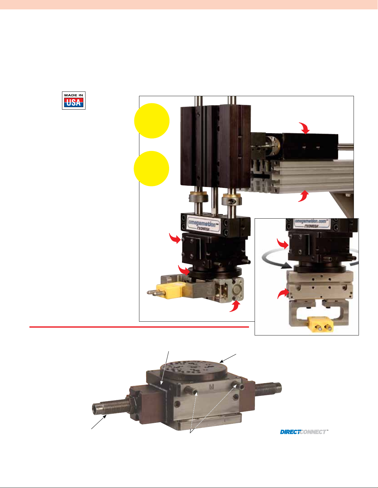
No Adaptor
Plates
Required!
Rotary
Positioning
Rotation
up to 180°
ODRF-004
turntable
module
to attach
grippers
DPP-10M-12 parallel gripper,
with OSTW-K-M thermocouple
connector visit omega.com
DLT-10M-E-C-50 linear slide
visit omega.com
DMEX mounting
stanchions,
visit omega.com
DRF-075M-180
Gripper
(sold
separately)
proDuct features
Sensor Mounting Slots
Standard mounting slots for Magneto Resistive
Sensors magnet mounted in piston standard
(sensors sold separately).
Extremely
Rugged Design
Pinion is supported with
upper and lower sealed
ball bearings.
End Stop Deceleration
(-A Option)
Shock absorbers decelerates
load at end of stroke.
Case Hardened
Rack and pinion are
case hardened for wear
and long life.
Black Anodize Body
The body and End Plates are
Black anodized, steel parts are
black oxide.
Rotational Adjustments
All rotational adjustments made
from front face. Adjustments are
locked with set screw on side.
C-15
Flange Mounting
Turntable has
DIRECTCONNECT
mounting pattern
DRF-075M-90-A
shown close
to actual size.
Tapped and Dowel mounting surface
on bottom of body and on turntable.
One Piece Body
One piece lightweight aircraft
quality aluminum body.
Dowel Holes
Slip fit dowel pin holes
in bottom body, and on
turntable.
Piston
Made of Delrin® for
extended life.
Mounting Patterns
Page 2
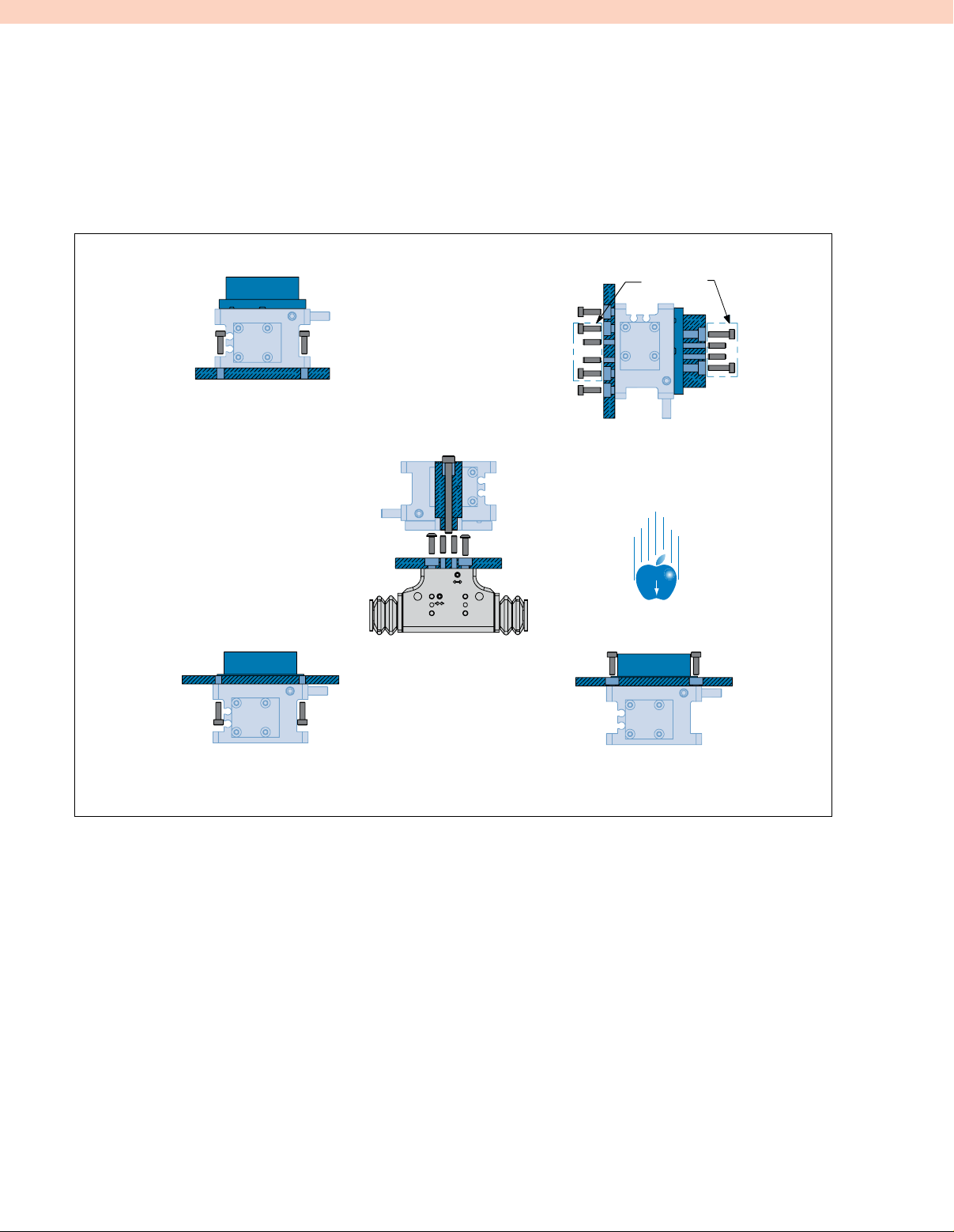
Directconnect
Mounting
mounting information
Directconnect
Mounting
Directconnect
Mounting
Directconnect
Mounting
Rotaries can be mounted and operated in any orientation.
Mounting through bottom flange
clearance holes into tapped holes
in customer application.
DIRECTCONNECT
Mounting: Gripper is
mounted from the under
side of Turntable with
Button Head screws and
slip fit dowels. Turntable
is then mounted to rotary
with one screw through the
center of the pinion and
two slip fit dowel pins.
Directconnect
Mounting
Body mounts with screws
and slip fit dowels from
bottom. Payload is attached
with screw and slip fit dowels.
G
Mounting through top flange
clearance holes into tapped holes
in customer application.
SPECIFICATIONS
PNEUMATIC SPECIFICATIONS
Pressure Operating Range: 3 to 7 bar
(40 to 100 psi)
Cylinder Type: Double acting
Dynamic Seals: Internally lubricated buna-N
Valve Required to Operate: 4-way, 2-position
AIR QUALITY REQUIREMENTS
Air Filtration: 40 micron or better
Air Lubrication: Not necessary*
Air Humidity: Low moisture content (dry)
Top mounting from underside of table
using tapped holes in body top flange.
Temperature Operating Range:
Buna-N Seals (Standard): -35 to 80°C
(-30 to 180°F)
With Shocks: 0 to 66°C (32 to 150°F)
MAINTENANCE SPECIFICATIONS
Expected Life:
Normal Application: 5 million cycles
With Preventative Maintenance:
10+ million cycles*
Field Repairable: Yes
Seal Repair Kits Available: Yes
* Addition of lubrication will greatly increase service life.
C-16
Page 3
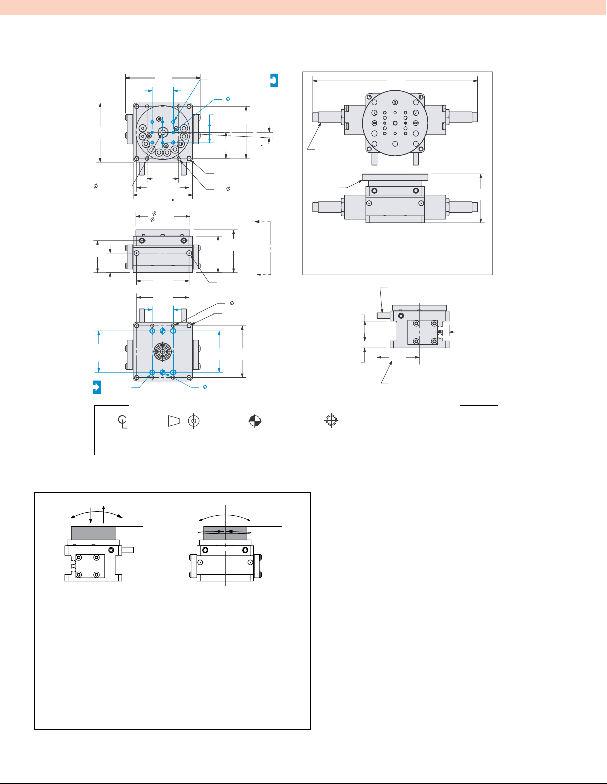
"Z"
Drf-075m
54 ±0.5
(2.13 ±0.02)
[4.4] THRU
29.4
(1.156)
17.9
(0.705)
1.5000
[38.10]
DOWELS
[M5
(2.69)
19.05
(0.7500)
(1.125)
47.6 (1.875)
54.0 (2.125)
UN IT SHOWN IN 0 POSITIO N
ROTATED FU LLY C W
(1.938)
(1.886)
(1.875)
(0.750)
X 5 DP]
68
28.5
49.2
47.9
47.6
19.1
[M3 X 5 DP]
DO NOT EXCEED DEPT
[3
H7 X 4 DP]
19.05
47.6
(0.7500)
(1.875)
23.8
(0.938)
[M4] THRU TOP FLANGE
[3.3] THRU TOP FLANGE
4X
38.8
(1.529)
33.4
(1.313)
2X
[M5 X 5 DP]
AIR PORTS
[3.3] THRU BOTTOM FLANGE
[M4] THRU BOTTOM FLANGE
47.6
38.1
(1.875)
(1.500)
[M
5 H7 X 5 DP]
H
1 TO 3°
OVERTRAVEL
BOTH ENDS
"A "
"A "
151
(5.93)
M 10 X 1. 0
O DRF-003
SH OW N
44
(1.76)
-A SHOCK ABSO RBER OPTIO N
SHOWN ABOVE
SHOCKS FULLY ACTIVATED ONLY AT
45°, 90°, 135°, AND 180° ROTATIONS
INTERMEDIATE ROTAT ION WILL REDUCE
SHOCK ABSORBER ABILITY AND PAYLOAD
MUST BE REDUCED
HA RD STOP
AD JUST IN G SCREWS
2X 18
(0.7 2)
2X 6
(0.2 5)
C
37
PINIO N
2X 6
(0.2 5)
M AX FOR STANDA RD ROTATION S
(1.53)
VI EW "A-A"
L
UNLESS OTHERWISE NOTED ALL TOLERANCES ARE AS SHOWN BELOW
Dimensions are
symmetrical about
centerline
Third Angle
Projection
Dimensions: mm (inch)
DIRECTCONNECTTM dimensions shown in blue
"T"
"C"
W,J
"M",x
"X"
Loading Capacity Static Dynamic
Maximum Tensile T 44 N (10 lb) 9 N (2 lb)
Maximum Compressive C 89 N (20 lb) 18 N (4 lb)
Maximum Moment Mx 2.3 Nm (20 in-lb) 0.5 Nm (4 in-lb)
Maximum Moment My 2.3 Nm (20 in-lb) 0.5 Nm (4 in-lb)
Maximum Payload W
(with Shocks)
Maximum Inertia J
(with Shocks)
Note: Higher payloads and inertia possible with external shocks and stops.
All Dowel Holes are SF (Slip Fit).
Locational Tolerance
±0.0005" or [±0.013 mm]
"M",y
"Y"
"Z"
0.45 kg (1.0 lb)
1.8 x 10⁻⁴ N-m-sec
(
0.0016 in-lb-sec2)
Metric Threads
Course Pitch
Imperial inch
0.00 = ±0.01 0. = ±0.25
0.000 = ±0.005 0.0 = ±0.13
0.0000 = ±0.000 0.00 = ±0.013
Metric mm
SPECIFICATIONS
Maximum Payload with Shocks (-A): 0.45 kg (1 lb)
Maximum Payload without Shocks: 0.23 kg (0.5 lb)
Maximum Payload Inertia with Shocks (-A):
1.8 x 10
Maximum Payload Inertia without Shocks:
9.0 x 10⁻⁵ N-m-sec2 (0.0008 in-lb-sec2)
Maximum Torque @ 7 bar (100 psi): 0.9 N-m (8.3 lb-in)
Maximum Rotation: 180°
Pitch Diameter of Pinion: 9.5 mm (0.375")
Weight with Shocks (-A Option): 0.34 kg (0.72 lb)
Weight without Shocks: 0.24 kg (0.54 lb)
Pressure Range: 3 to 7 bar (40 to 100 psi)
Bore: 19.1 mm (0.750")
Displacement (180°): 5.1 cm
Actuation Time [180° @ 7 bar (100 psi)]: 0.38 sec (0.38 sec)
Actuation Time [90° @ 7 bar (100 psi)]: 0.29 sec (0.29 sec)
Over Travel (Each End): 1 to 3°
Temperature Range without Shocks: -35 to 82°C (-30 to 180°F)
2
Temperature Range with Shocks (-A): 0 to 66°C (32 to 150°F)
End Stop Adjustability (Each End): 23°
Repeatability: ±0.02°
Valve Required to Actuate: 4-way, 2-position
-4
N-m-sec2 (0.0016 in-lb-sec2)
3
(0.31 in3)
C-17
Page 4

71 ±0.5
"Z"
(2.78 ±0.02)
(0.7500)
[ 5.3] THRU
33.3
(1.313)
38.10
(1.5000)
DOWELS
[M
19.05
21.4
(0.844)
M5 X 8DP
5 H7 X 7 DP]
86
(3.38)
19.05
(0.7500)
34.9
(1.375)
60.3 (2.375)
70.6 (2.781)
UN IT SHOWN IN 0 POSITIO N
ROTATED FU LLY C W
60.3
(2.375)
62.7
(2.468)
60.3
(2.375)
38.1
(1.500)
19.1
(0.750)
Drf-094m
[M3 X 6 DP]
DO NOT EXCEED DEPT
[3 H7 X 5 DP
30.6
(1.203)
[M5] THRU TOP FLANGE
[5.1] THRU TOP FLANGE
4X
38.9
(1.531)
(1.500)
]
61.1
(2.406)
1 TO 3°
OVERTRAVEL
BOTH ENDS
"A "
44.8
(1.764)
"A "
[M5 X 11 DP]
2X
AIR PORT S
[5.1] THRU BOTTOM FLANGE
[M5] THRU BOTTOM FLANGE
19.1
61.1
(2.406)
H
M 12 X 1. 0
O DRF-009
SH OW N
-A SHOCK ABSO RBER OPTIO N
SHOWN ABOVE
SHOCKS FULLY ACTIVATED ONLY AT
45°, 90°, 135°, AND 180° ROTATIONS
INTERMEDIATE ROTAT ION WILL REDUCE
SHOCK ABSORBER ABILITY AND PAYLOAD
MUST BE REDUCED
21
(0.81)
7
(0.28)
189
(7.45)
HA RD STOP
AD JUST IN G SCREWS
C
PINIO N
L
49
(1.85)
VI EW "A-A"
M AX FOR STANDA RD ROTATION S
2X 10
(0.4 1)
52
(2.04)
UNLESS OTHERWISE NOTED ALL TOLERANCES ARE AS SHOWN BELOW
Dimensions are
symmetrical about
centerline
Third Angle
Projection
Dimensions: mm (inch)
DIRECTCONNECTTM dimensions shown in blue
"T"
"C"
W,J
"M",x
"X"
Loading Capacity Static Dynamic
Maximum Tensile T 67 N (15 lb) 13 N (3 lb)
Maximum Compressive C 133 N (30 lb) 27 N (6 lb)
Maximum Moment Mx 5.6 Nm (50 in-lb) 1.1 Nm (10 in-lb)
Maximum Moment My 5.6 Nm (50 in-lb) 1.1 Nm (10 in-lb)
Maximum Payload W
(with Shocks)
Maximum Inertia J
(with Shocks)
Note: Higher payloads and inertia possible with external shocks and stops.
All Dowel Holes are SF (Slip Fit).
Locational Tolerance
±0.0005" or [±0.013 mm]
"M",y
"Y"
"Z"
1.4 kg (3 lb)
1.3 x 10⁻³ N-m-sec
(
0.0111 in-lb-sec2)
Metric Threads
Course Pitch
Imperial inch
0.00 = ±0.01 0. = ±0.25
0.000 = ±0.005 0.0 = ±0.13
0.0000 = ±0.000 0.00 = ±0.013
Metric mm
SPECIFICATIONS
Maximum Payload with Shocks (-A): 1.4 kg (3 lb)
Maximum Payload without Shocks: 0.68 kg (1.5 lb)
Maximum Payload Inertia with Shocks (-A):
1.3 x 10
Maximum Payload Inertia without Shocks:
6.3 x 10⁻⁴ N-m-sec2 (0.0056 in-lb-sec2)
Maximum Torque @ 7 bar (100 psi): 1.9 N-m (17.3 lb-in)
Maximum Rotation: 180°
Pitch Diameter of Pinion: 12.7 mm (0.500")
Weight with Shocks (-A Option): 0.64 kg (1.4 lb)
Weight without Shocks: 0.50 kg (1.1 lb)
Pressure Range: 3 to 7 bar (40 to 100 psi)
Bore: 23.8 mm (0.938")
Displacement (180°): 9.0 cm3 (0.55 in3)
Actuation Time [180° @ 7 bar (100 psi)]: 0.38 sec (0.38 sec)
Actuation Time [90° @ 7 bar (100 psi)]: 0.29 sec (0.29 sec)
Over Travel (Each End): 1 to 3°
Temperature Range without Shocks: -35 to 82°C (-30 to 180°F)
2
Temperature Range with Shocks (-A): 0 to 66°C (32 to 150°F)
End Stop Adjustability (Each End): 23°
Repeatability: ±0.02°
Valve Required to Actuate: 4-way, 2-position
-3
N-m-sec2 (0.0111 in-lb-sec2)
C-18
Page 5

"Z"
Drf-106m
100 ±0.5
(3.94 ±0.02)
42.9
(1.688)
76.20
(3.0000)
DOWELS
5 H7 X 5 DP]
[M
38.10
(1.5000)
26.2
(1.031)
38.10
(1.5000)
DOWELS
X 7 DP
M5
115
(4.54)
38.10
(1.5000)
50.8
(2.000)
82.6 (3.250)
100.0 (3.938)
UN IT SHOWN IN 0 POSITIO N
ROTATED FU LLY C W
86.5
(3.406)
93.7
(3.690)
63.5
(2.500)
38.1
(1.500)
19.1
(0.750)
[M5 X 8 DP]
DO NOT EXCEED DEPT
[5 H7 X 5 DP]
82.6
(3.250)
41.3
(1.625)
THRU TOP FLANGE
THRU TOP FLANGE
57.9
(2.279)
49.2
(1.938)
[M5 X 13 DP]
2X
AIR PORTS
[M8 H7 THRU BOTTOM FLANGE
[M10] THRU BOTTOM FLANGE
[5.5] THRU BOTTOM FLANGE
38.1
(1.500)
1 TO 3°
OVERTRAVEL
BOTH ENDS
[M6]
4X [6.0]
"A "
"A "
76.2
(3.000)
H
]
M 14 X 1. 5
O DRF-015
SH OW N
250
(9.84)
-A SHOCK ABSO RBER OPTIO N
SHOWN ABOVE
SHOCKS FULLY ACTIVATED ONLY AT
45°, 90°, 135°, AND 180° ROTATIONS
INTERMEDIATE ROTAT ION WILL REDUCE
SHOCK ABSORBER ABILITY AND PAYLOAD
MUST BE REDUCED
HA RD STOP
AD JUST IN G SCRE W
29
(1.13)
C
8
(0.31)
74
(3.03)
M AX FOR STANDA RD ROTATION S
L
VI EW "A-A"
PINIO N
2X 19
(0.7 5)
66
(2.59)
UNLESS OTHERWISE NOTED ALL TOLERANCES ARE AS SHOWN BELOW
Dimensions are
symmetrical about
centerline
Third Angle
Projection
Dimensions: mm (inch)
DIRECTCONNECTTM dimensions shown in blue
"T"
"C"
W,J
"M",x
"X"
Loading Capacity Static Dynamic
Maximum Tensile T 111 N (25 lb) 22 N (5 lb)
Maximum Compressive C 89 N (50 lb) 44 N (10 lb)
Maximum Moment Mx 8.5 Nm (75 in-lb) 1.7 Nm (15 in-lb)
Maximum Moment My 8.5 Nm (75 in-lb) 1.7 Nm (15 in-lb)
Maximum Payload W
(with Shocks)
Maximum Inertia J
(with Shocks)
Note: Higher payloads and inertia possible with external shocks and stops.
All Dowel Holes are SF (Slip Fit).
Locational Tolerance
±0.0005" or [±0.013 mm]
"M",y
"Y"
"Z"
3.6 kg (8 lb)
4.7 x 10⁻³ N-m-sec
(
0.0414 in-lb-sec2)
Metric Threads
Course Pitch
Imperial inch
0.00 = ±0.01 0. = ±0.25
0.000 = ±0.005 0.0 = ±0.13
0.0000 = ±0.000 0.00 = ±0.013
Metric mm
SPECIFICATIONS
Maximum Payload with Shocks (-A): 3.6 kg (8 lb)
Maximum Payload without Shocks: 1.8 kg (4 lb)
Maximum Payload Inertia with Shocks (-A):
4.7 x 10
Maximum Payload Inertia without Shocks:
2.3 x 10⁻⁵ N-m-sec2 (0.0207 in-lb-sec2)
Maximum Torque @ 7 bar (100 psi): 3.8 N-m (33.2 lb-in)
Maximum Rotation: 180°
Pitch Diameter of Pinion: 19.1 mm (0.750")
Weight with Shocks (-A Option): 1.4 kg (3.1 lb)
Weight without Shocks: 1.1 kg (2.5 lb)
Pressure Range: 3 to 7 bar (40 to 100 psi)
Bore: 27.0 mm (1.063")
Displacement (180°): 19.0 cm
Actuation Time [180° @ 7 bar (100 psi)]: 0.60 sec (0.60 sec)
Actuation Time [90° @ 7 bar (100 psi)]: 0.45 sec (0.45 sec)
Over Travel (Each End): 1 to 3°
Temperature Range without Shocks: -35 to 82°C (-30 to 180°F)
2
Temperature Range with Shocks (-A): 0 to 66°C (32 to 150°F)
End Stop Adjustability (Each End): 23°
Repeatability: ±0.02°
Valve Required to Actuate: 4-way, 2-position
-3
N-m-sec2 (0.0414 in-lb-sec2)
3
(1.16 in3)
C-19
Page 6

"Z"
Drf-131m
133 ±0.5
(5.25 ±0.02)
[M10 X 16 DP
76.20
(3.0000)
DOWELS
(1.5000)
53.7
(2.115)
38.10
(1.5000)
DOWELS
38.10
UN IT SHOWN IN 0 POSITIO N
ROTATED FU LLY C W
33.7
(1.325)
]
153
(6.02)
38.10
(1.5000)
57.2
(2.250)
114.3 (4.500)
133.4 (5.250)
104.8 (4.125)
120.7 (4.750)
114.3 (4.500)
76.2 (3.000)
[M5 X 9 DP]
DO NOT EXCEED DEPT
[5 H7 X 6 DP
114.3
(4.500)
57.2
(2.250)
OVERTRAVEL
BOTH ENDS
THRU TOP FLANGE
4X [9.9]
THRU TOP FLANGE
71.7
(2.821)
62.2
(2.450)
[M8 H7 X 10 DP
38.1
(1.500)
[G1/8 X 8 DP]
2X
AIR PORTS
"A "
"A "
[9.9]
THRU BOTTOM FLANGE
[M10]
THRU BOTTOM FLANGE
76.2
(3.000)
H
1 TO 3°
]
114.3
(4.500)
301
(11.85)
]
M 20 X 1. 5
O DRF-021
SH OW N
-A SHOCK ABSO RBER OPTIO N
SHOWN ABOVE
SHOCKS FULLY ACTIVATED ONLY AT
45°, 90°, 135°, AND 180° ROTATIONS
INTERMEDIATE ROTAT ION WILL REDUCE
SHOCK ABSORBER ABILITY AND PAYLOAD
MUST BE REDUCED
HA RD STOP
AD JUST IN G SCREWS
37
(1.44)
2X 19
(0.8 1)
81
(3.20)
X 7 DP]
[M5
38.1
(1.500)
19.1
(0.750)
5 H7 X 5 DP]
[M
UNLESS OTHERWISE NOTED ALL TOLERANCES ARE AS SHOWN BELOW
Dimensions are
symmetrical about
centerline
Third Angle
Projection
Dimensions: mm (inch)
DIRECTCONNECTTM dimensions shown in blue
"T"
"C"
W,J
"M",x
"X"
Loading Capacity Static Dynamic
Maximum Tensile T 222 N (50 lb) 44 N (10 lb)
Maximum Compressive C 445 N (100 lb) 89 N (20 lb)
Maximum Moment Mx 11.3 Nm (100 in-lb) 2.3 Nm (20 in-lb)
Maximum Moment My 11.3 Nm (100 in-lb) 2.3 Nm (20 in-lb)
Maximum Payload W
(with Shocks)
Maximum Inertia J
(with Shocks)
Note: Higher payloads and inertia possible with external shocks and stops.
All Dowel Holes are SF (Slip Fit).
Locational Tolerance
±0.0005" or [±0.013 mm]
1.1 x 10⁻² N-m-sec
(
0.0970 in-lb-sec2)
"M",y
"Y"
"Z"
6.8 kg (15 lb)
10
(0.38)
Metric Threads
Course Pitch
86
C
(3.62)
M AX FOR STANDA RD ROTATION S
Imperial inch
0.00 = ±0.01 0. = ±0.25
0.000 = ±0.005 0.0 = ±0.13
0.0000 = ±0.000 0.00 = ±0.013
PINION
L
VI EW "A-A"
Metric mm
SPECIFICATIONS
Maximum Payload with Shocks (-A): 6.8 kg (15 lb)
Maximum Payload without Shocks: 3.4 kg (7.5 lb)
Maximum Payload Inertia with Shocks (-A):
1.1 x 10
Maximum Payload Inertia without Shocks:
5.5 x 10⁻³ N-m-sec2 (0.0485 in-lb-sec2)
Maximum Torque @ 7 bar (100 psi): 7.6 N-m (67.6 lb-in)
Maximum Rotation: 180°
Pitch Diameter of Pinion: 25.4 mm (1.000")
Weight with Shocks (-A Option): 3.1 kg (6.8 lb)
Weight without Shocks: 2.9 kg (6.3 lb)
Pressure Range: 3 to 7 bar (40 to 100 psi)
Bore: 33.4 mm (1.313")
Displacement (180°): 34.6 cm3 (2.11 in3)
Actuation Time [180° @ 7 bar (100 psi)]: 0.87 sec (0.87 sec)
Actuation Time [90° @ 7 bar (100 psi)]: 0.68 sec (0.68 sec)
Over Travel (Each End): 1 to 3°
Temperature Range without Shocks: -35 to 82°C (-30 to 180°F)
2
Temperature Range with Shocks (-A): 0 to 66°C (32 to 150°F)
End Stop Adjustability (Each End): 23°
Repeatability: ±0.02°
Valve Required to Actuate: 4-way, 2-position
-2
N-m-sec2 (0.0970 in-lb-sec2)
C-20
Page 7

Turntable
ODRF-04
ø 60 (2.38)
Drf-075m,
094m, 106m
DF
DQ*
DD
SURFACE
“A”
DB*
DC
B
* DIMENSIONS ALSO APPLY TO BLANK
TURNTABLE
C'BORE FOR BUTTON HEAD SCREWS
Drf-131m
DF
DH
DD
DC*
DJ
SURFACE
“A”
B
* DIMENSIONS ALSO APPLY TO BLANK
TURNTABLE
C'BORE"S FOR BUTTON HEAD SCREWS
DB
DC*
DB*
DC
DH
DD
DK
Dimensions:
l DIRECTCONNECT Turntable,
Easily Removed, Pin Located
DD
DQ*
DS
DU
l High Quality Aircraft Aluminum, Black Anodized Finish
l Mounts Through Pinion with One Screw and Two Dowels
l No Machining Required, DIRECTCONNECT Grippers Mount Directly
l 90° and 180° Orientations in Stock
Sensor and
Flow Controls
l PNP and NPN Magneto Resistive Available
l Sensors Are Slot Mounted, No Mounting Kits Required
l Precision Rotary Adjustments Made from Face and Locked with Set Screws
l Tubing, Fittings and Additional Pneumatic Controls and Accessories
Available, visit omega.com or Consult Sales
DM
DP
Dimensions: mm (inch)
DIRECTCONNECTTM
dimensions shown in blue
mm (inch)
Dimensions:
mm (inch)
SURFACE "A"
DIRECTCONNECT
Turntable
18.1
(0.715)
OHSN-017
OHSP-017
25.4
(1.00)
DIRECTCONNECT DIMENSIONS
STANDARD MOUNTING PATTERN
FOR ALL SIZES
DA 9.5 mm
DB 19.1 mm
DC 38.1 mm
DD 5 mm THRU
DF C’BORE FOR M5 BUTTON
HEAD SCREW
DH M5 THRU
DJ 76.2 mm
DK 10 mm THRU
DM C’BORE FOR 10 mm
BUTTON HEAD SCREW
DP M10 THRU
DQ 3 H7 THRU
DS C’BORE FOR M3 BUTTON
HEAD SCREW
DU M3 THRU
OHSN-011
OHSP-011
TURNTABLE PLATE DIAMETER AND THICKNESS “B”
THICKNESS DIAMETER
MODEL NO. TURNTABLE NO. mm (inch) mm (inch)
DRF-075M ODRF-002/004 5.9 (0.23) 60 ±0.8 (2.38 ±0.03)
DRF-094M ODRF-008/010 7.1 (0.281) 76 ±0.8 (3.00 ±0.03)
DRF-106M ODRF-014/016 7.9 (0.313) 102 ±0.8 (4.00 ±0.03)
DRF-131M ODRF-020/022 9.5 (0.375) 133 ±0.8 (5.25 ±0.03)
C-21
Page 8

To Order Visit omega.com/drf_075m_094m for Pricing and Details
DEPTH WIDTH HEIGHT MAX PAYLOAD MAX WEIGHT
MODEL NO. mm (inch) mm (inch) mm (inch) Kg (lbs) ROTATION Kg (lbs)
DRF-075M-90 54 (2.13) 69 (2.69) 37 (1.52) 0.23 (0.5) 90° 0.24 (0.54)
DRF-075M-180 54 (2.13) 69 (2.69) 37 (1.52) 0.23 (0.5) 180° 0.24 (0.54)
DRF-075M-90-A 54 (2.13) 151 (5.93) 37 (1.52) 0.45 (1) 90° 0.34 (0.72)
DRF-075M-180-A 54 (2.13) 151 (5.93) 37 (1.52) 0.45 (1) 180° 0.34 (0.72)
DRF-094M-90 71 (2.78) 86 (3.36) 49 (1.76) 0.68 (1.50) 90° 0.50 (1.10)
DRF-094M-180 71 (2.78) 86 (3.36) 49 (1.76) 0.68 (1.50) 180° 0.50 (1.10)
DRF-094M-90-A 71 (2.78) 189 (7.45) 49 (1.76) 1.4 (3.00) 90° 0.64 (1.40)
DRF-094M-180-A 71 (2.78) 189 (7.45) 49 (1.76) 1.4 (3.00) 180° 0.64 (1.40)
DRF-106M-90 100 (3.94) 115 (4.54) 58 (2.28) 1.8 (4.00) 90° 1.1 (2.50)
DRF-106M-180 100 (3.94) 115 (4.54) 58 (2.28) 1.8 (4.00) 180° 1.1 (2.50)
DRF-106M-90-A 100 (3.94) 250 (9.84) 58 (2.28) 3.6 (8.00) 90° 1.4 (3.10)
DRF-106M-180-A 100 (3.94) 250 (9.84) 58 (2.28) 3.6 (8.00) 180° 1.4 (3.10)
DRF-131M-90 133 (5.25) 153 (6.02) 72 (2.82) 3.4 (7.50) 90° 2.9 (6.30)
DRF-131M-180 133 (5.25) 153 (6.02) 72 (2.82) 3.4 (7.50) 180° 2.9 (6.30)
DRF-131M-90-A 133 (5.25) 301 (11.85) 72 (2.82) 6.8 (15.00) 90° 3.1 (6.80)
DRF-131M-180-A 133 (5.25) 301 (11.85) 72 (2.82) 6.8 (15.00) 180° 3.1 (6.80)
Ordering Example: DRF-075M-90-A, precision rotary actuator with 90° of rotation and built in shock absorber. Recommend accessories
include 2 sensors and 2 pneumatic flow controls for each slide, along with a 4-way 2 position valve. DRF-075M models: actuation time
[180° @ 7 bar (100 psi) 0.38 seconds], actuation time [90° @ 7 bar (100 psi) 0.29 seconds]. DRF-094M models: actuation time [180° @ 7 bar
(100 psi) 0.38 seconds], actuation time [90° @ 7 bar (100 psi) 0.29 seconds]. DRF-106M models: actuation time [180° @ 7 bar (100 psi)
0.38 seconds], actuation time [90° @ 7 bar (100 psi) 0.29 seconds]. DRF-131M models: actuation time [180° @ 7 bar (100 psi) 0.38 seconds],
actuation time [90° @ 7 Bar (100 psi) 0.29 seconds]. All models end stop adjustability 23°, over travel (each end) 1 to 3°.
Detailed specification and CAD drawings available at omega.com.
Accessories
MODEL NO. DESCRIPTION
SENSOR ACCESSORIES
OHSP-011 PNP magneto resistive sensor 90° barrell with quick disconnect fitting
OHSN- 011 NPN magneto resistive sensor 90° barrell with quick disconnect fitting
OHSP-017 PNP magneto resistive sensor short barrell with quick disconnect fitting
OHSN- 017 NPN magneto resistive sensor short barrell with quick disconnect fitting
CABL-010 Quick disconnect cable 2 m (6.6') long
CABL-013 Quick disconnect cable 5 m (16') long
PNEUMATIC ACCESSORIES
Pneumatic Tubing Polyurethane tubing in multiple diameters and colors available, visit omega.com
Pneumatic Fittings Rotary sizes 075M to 106M use M5 threads, 131M use 1/8G threads
Pneumatic Flow Controls Adjustable flow control fittings and directional control valves, visit omega.com
MECHANICAL ACCESSORIES
ODRF-002 Rotary size 075M blank turn table, machining required
ODRF-004 Rotary size 075, DirectConnect turntable metric, direct mounting for gripper,
ODRF-008 Rotary size 094M blank turn table, machining required
ODRF-010 Rotary size 094, DirectConnect turntable metric, direct mounting for gripper,
ODRF-014 Rotary size 106M blank turn table, machining required
ODRF-016 Rotary size 106M, DirectConnect turn table, direct mounting for grippers,
ODRF-020 Rotary size 131M blank turn table, machining required
ODRF-022 Rotary size 131M, DirectConnect turn table, direct mounting for grippers,
DMM Series Aluminum extruded mounting stanchions for slides and thrusters, visit¡ omega.com
no machining necessary
no machining necessary
no machining necessary
no machining necessary
C-22
 Loading...