

Page 1
User’s Guide
Shop online at
omega.com
e-mail: info@omega.com
For latest product manuals:
omegamanual.info
DPF-520 Series
Xxxxx Xxxxxxxx
Flow Computer
XXXXXX
Page 2

OMEGAnet®Online Service Internet e-mail
omega.com info@omega.com
Servicing North America:
U.S.A.: Omega Engineering, Inc., One Omega Drive, P.O. Box 4047
ISO 9001 Certified Stamford, CT 06907-0047 USA
Toll Free: 1-800-826-6342 TEL: (203) 359-1660
FAX: (203) 359-7700 e-mail: info@omega.com
Canada: 976 Bergar
Laval (Quebec), Canada H7L 5A1
Toll-Free: 1-800-826-6342 TEL: (514) 856-6928
FAX: (514) 856-6886 e-mail: info@omega.ca
For immediate technical or application assistance:
U.S.A. and Canada: Sales Service: 1-800-826-6342/1-800-TC-OMEGA
Customer Service: 1-800-622-2378/1-800-622-BEST
Engineering Service: 1-800-872-9436/1-800-USA-WHEN
Mexico: En Español: 001 (203) 359-7803 FAX: (001) 203-359-7807
info@omega.com.mx e-mail: espanol@omega.com
®
®
®
Servicing Europe:
Benelux: Managed by the United Kingdom Office
Toll-Free: 0800 099 3344 TEL: +31 20 347 21 21
FAX: +31 20 643 46 43 e-mail: sales@omega.nl
Czech Republic: Frystatska 184
733 01 Karviná, Czech Republic
Toll-Free: 0800-1-66342 TEL: +420-59-6311899
FAX: +420-59-6311114 e-mail: info@omegashop.cz
France: Managed by the United Kingdom Office
Toll-Free: 0800 466 342 TEL: +33 (0) 161 37 29 00
FAX: +33 (0) 130 57 54 27 e-mail: sales@omega.fr
Germany/Austria: Daimlerstrasse 26
D-75392 Deckenpfronn, Germany
Toll-Free: 0 800 6397678 TEL: +49 (0) 7059 9398-0
FAX: +49 (0) 7056 9398-29 e-mail: info@omega.de
United Kingdom: OMEGA Engineering Ltd.
ISO 9001 Certified One Omega Drive, River Bend Technology Centre, Northbank
Irlam, Manchester M44 5BD England
Toll-Free: 0800-488-488 TEL: +44 (0)161 777-6611
FAX: +44 (0)161 777-6622 e-mail: sales@omega.co.uk
It is the policy of OMEGA Engineering, Inc. to comply with all worldwide safety and EMC/EMI
regulations that apply. OMEGA is constantly pursuing certification of its products to the European New
Approach Directives. OMEGA will add the CE mark to every appropriate device upon certification.
The information contained in this document is believed to be correct, but OMEGA accepts no liability for any
errors it contains, and reserves the right to alter specifications without notice.
WARNING: These products are not designed for use in, and should not be used for, human applications.
Page 3
GENERAL INFORMATION, FEATURES, DIMENSIONS, SPECIFICATIONS
1/2" NPT
5.67"
The DPF-520 Series is a batching ow processor with additional
output controls. It is designed for use with Omega ow meters
and ow sensors, as well as other manufacturer’s products
which have frequency output proportional to ow. In addition
to batch functions, the DPF-520 Series indicates ow rate, and
other data in large 3/8” (9.66 mm) digits on an easily-read,
backlit display. Units of measure are user selectable, and range
from milliliters per second to millions of gallons per day. The unit
can be 110 Vac powered with a standard 3-wire cord (included),
220 Vac powered (optional), or DC powered through an internal
terminal strip (battery not included).
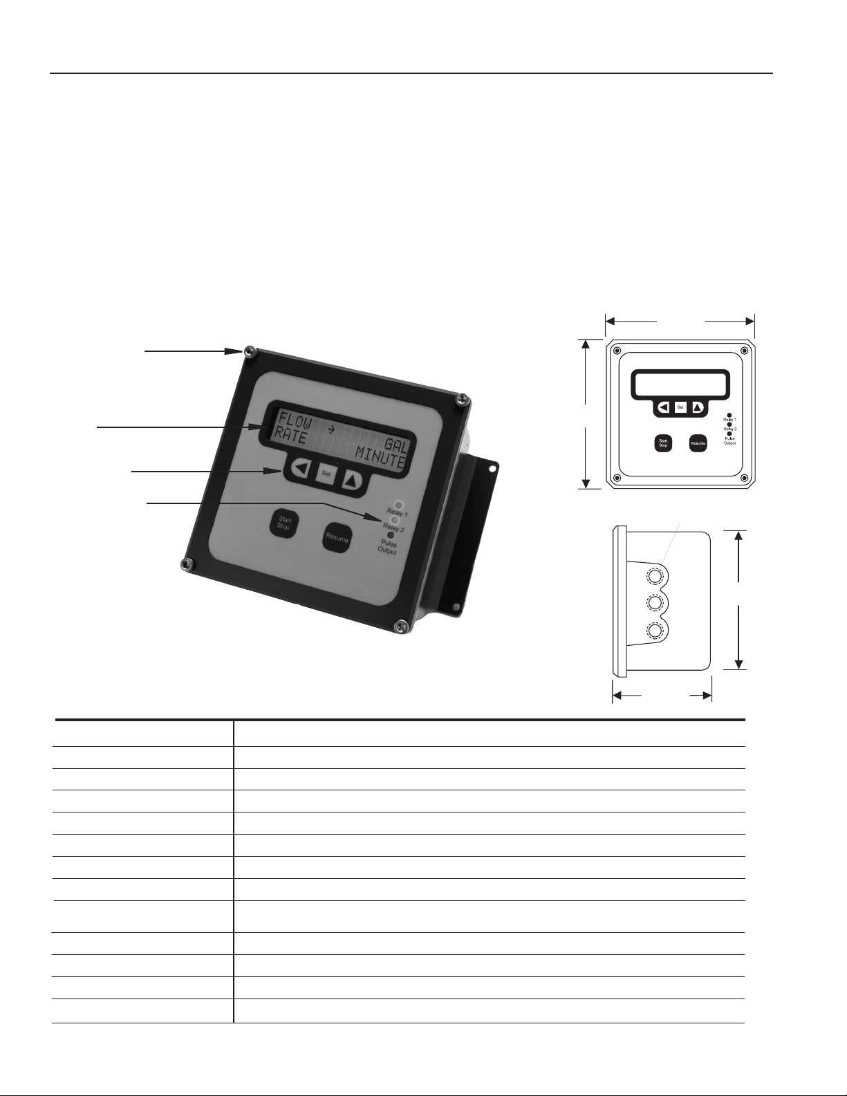
FEATURES
Cover Screws*
Display
Setting Keys
Indicator Lights
An analog output of 4-20 mA is available both in active and
passive loop conguration, and in 0-5 Vdc or 0-10 Vdc outputs,
and can be used in applications such as ow rate logging. Two
programmable pulse scaled outputs are also standard, and can
be used, for example, to provide proportional chemical feed with
a pulse-responsive metering pump.
The housing is supplied with two brackets for wall-mount
applications, or the top/bottom housings can be easily
separated and reassembled for panel-mount.
DIMENSIONS
6.42"
6.42"
1/2" NPT
*Can be ordered cross-drilled for seal wire
SPECIFICATIONS*
Power
Temperature
Enclosure
Batch Outputs
Max Pulse Output
Memory Type
Sensor Power
Display
Units
Analog Output
Sensor Input
Environmental
Setup Memory
*Specications subject to change
115 Vac, 50/60 Hz @ 125 mA, (220 Vac optional), 12 Vdc @ 750 mA
32˚ - 130˚ F (0˚ - 55˚ C)
Precision cast aluminum, NEMA 4X, panel or wall mount conguration
Two form C (SPDT) relays, 115 Vac 6A max
100 mA at 60 Vac/Vdc, opto-isolated, open-collector
Non-volatile EEPROM with auto-backup
12 Vdc, 10 mA
Totalizer = 8 digit Rate = 5 digit, backlit
Volume = Gallons, cubic feet, cubic meters, millions of gallons, milliliters, uid ounces, pounds, liters
Time = Seconds, minutes, hours, days
4-20 mA passive opto-isolated; 4-20 mA active; 0-5 Vdc, or 0-10 Vdc
1-1000 Hz, ESD protected, interfaces to current sinking sensor output
NEMA 4X
Non-volatile EEPROM, auto-backup
5.67"
4.65"
Page 1
Page 4
•
•
SEN1
–G
SEN2
Alternate
DC power
Customer Supplies
1A Fuse
Pulse 1
Pulse 2
Pulse Outputs
(for metering pumps)
Regeneration Outputs
AC Power
Relay 1
Relay 2
Main power fuse
250mA
Line
Neutral
Ground
Ribbon connector
from display board
Resume
Start/Stop
Remote
Controls
NO
COM
NC
NO
COM
NC
Resume
COM
BATCH
+12
Power
Signal
Ground
RED
WHITE
BLACK
Meter
Dry contact
0-5 V or
0-10 V or
4-20 mA
Analog Switch*
Analog Header
A
+
-
B
Active
Passive
Jumpers
A
P
5V
10V
4-20mA
An Output
110 Vac
Jumpers
220 Vac
Jumper
*Consult Omega before
changing from factory preset
5.50"
gasket
PANEL
CUTOUT
5.50"
6.03"
6.03"
1/4" holes (4 required)
.375"
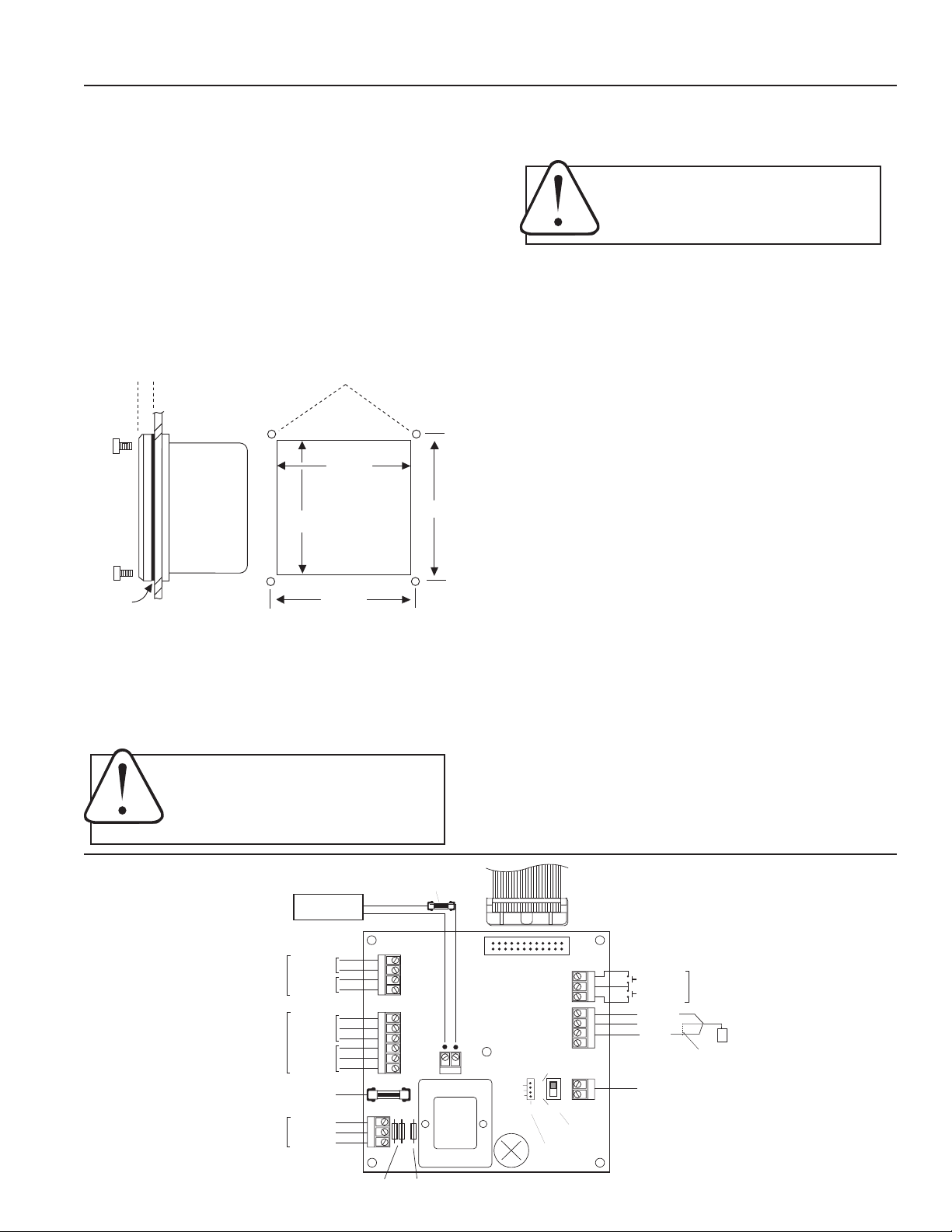
INSTALLATION, REPAIR, CONNECTIONS
Wall Mounting. Using the four screws provided, attach the
two foot brackets to the sides of the enclosure. Then attach
the unit to any secure surface by inserting screws through
the mounting holes in the foot brackets.
Panel Mounting. Follow the dimensions given for “Panel
Cutout”. Be sure to include the four corner screw holes.
After cutting and drilling, place the front plate on the front
side of the panel with its gasket against the panel, and the
remainder of the square housing on the back side. Slide the
screws through the four holes drilled in the panel, and into
the threaded holes in the housing. Tighten until the gasket
is rmly compressed against the panel.
PANEL CUT-OUT
Sensor Connection. Follow the “Connections” diagram to
connect either two or three wires from the ow meter or ow
sensor.
Caution: When the control is powered up,
relay or analog outputs may be present. If
this could be a hazard, wait to make external
connections until programming is complete.
Batch Control Connection (if used). Connect the valve or
other device(s) to be controlled for starting and stopping the
batch to the appropriate relay terminals. Note: if the staged
shutoff (“prewarn”) will not be used, connect to relay one
only. Relay 1 remains energized for the entire batch cycle. If
a staged shutoff is desired, connect the main valve to Relay
2 (early shutoff) and the low-ow valve to Relay 1.
Monitor Alarm Connection (if used). Connect the alarm devices to the appropriate relay terminals. Note that the relays have
both normally-open (NO) and normally-closed (NC) contacts.
Analog Connection (if used). This output can be congured
4-20 mA, 0-5 V or 0-10 V by placing a jumper in the correct
position on the analog header. The analog switch next to
the header selects active (powered) or passive (unpowered)
output. NOTE: Consult factory to change internal rmware
when changing switch position. When using the 12 Vdc
powered input you may only select passive output.
Expose Terminals. Remove the four screws which hold the
front plate to the lower housing ange. Remove front plate.
The display board is attached to this front plate. It is also
connected to the power board by a ribbon cable. This cable can
be disconnected while making connections. Connections can be
made inside the enclosure, or the terminals can be unplugged
by gentle tugging for easier access.
Caution: Always disconnect power to the
unit before opening the teminal cover. Do
not reconnect power until all connections
have been made and the teminal cover has
been replaced.
Connections
Power Connection. Connect AC or DC power as desired to
the appropriate terminals. For safety, if using AC power, be
sure to connect the ground terminal provided to a good earth
ground. If using 12 Vdc, use a 12 Vdc 500 mA power supply.
Replace the front panel, taking care to reconnect the ribbon
cable if it has been disconnected. When power is switched
on, the display should light up immediately with meaningful
letters or digits.
Repair
The only eld-repairable component on the DPF-520 is the
fuse. If failure is due to a cause other than a blown fuse, it
is necessary to replace the entire board stack. Contact your
distributor for information.
Page 2
Page 5

DPF-521
Flow Sensor
High -Flow
Valve
Low-Flow
Valve
Tank
DPF-520
Staged shut-off
at end of batch
High-Flow Valve
Low-Flow Valve
Relay 1
Relay 2
NC
COM
NO
NC
NO
COM
Power
Source
+
-
> DPF-521 Batch Controller
In Batch Processing Mode, the display indicates a ow rate on
the top line, and one of three user-selectable congurations
on the bottom line: an accumulated total ow (resettable), accumulated batch ow, or batch process bar graph. The batch
output is controlled via two relays. The main relay starts and
stops the batch as a set, or the auxiliary “prewarn” relay can
be used to operate a second valve. This allows increased accuracy by engaging a staged shut off at the end of the batch.
Settings
Use left arrow and up arrow keys to change settings. Press
SET to advance to next menu.
- SET Batch Size
Set the batch size for the desired number of units. If the
staged shut-off feature is not being used, this is the only setting required for the batch.
- SET Prewarn Size
This is only used for a staged shut-off. The number set is the
number of units early (before the end of the batch) that Relay
2 will shut off.
- SET Flow/Rate
Select the particular volume unit desired (gallons, liters, etc.).
Then switch to time units and select the time unit desired
(minutes, hours, etc.).
- SET Decimal
Select none, one, or two decimal places on the ow units.
- SET K-Factor
The unit will not function properly until this number is entered. The K-factor is simply the number of pulses which the
ow meter or ow sensor puts out per gallon of liquid. It is
marked on the Model/Serial tag of Omega ow meters and
ow sensor ttings. On adjustable depth ow sensors, the Kfactor must be taken from the chart in the ow sensor instructions, based on pipe size.
- SET Pulse (scaled) Output 1
An output pulse is activated at the selected volume intervals
if this feature is in use. If a pulse output is not needed, pulse
out does not need to be set.
- SET Pulse (scaled) Output 2
An output pulse is activated at the selected volume intervals
if this feature is in use. If a pulse output is not needed, pulse
out does not need to be set.
- SET 20 mA Rate
The “SET 20mA RATE” programs the maximum ow rate at
which the output is 20 mA full scale, at 5 V or 10 V.
- Clear Total
This function resets the accumulated total back to zero. It is
unrelated to the regeneration function, and can be ignored
unless it is needed.
Operation
Start Batch. Pressing the Start/Stop key starts the batch by
energizing Relay 1. The indicator for Relay 1 will light, indicating normal operation. The indicator for Relay 2 may also light,
depending on the prewarn setting. If staged shut-off is being
used, the Relay 2 indicator light should go out before the end
Page 3
of the batch, at the prewarn set point. The batch will continue
on to the set amount unless it is halted in the middle of the
process by pressing the Start/Stop key again.
Stop Batch/Resume Batch. Pressing the Start/Stop key anywhere in the batch will stop it. It will remain stopped until the
Resume key is pressed. Pressing the Start/Stop key again
allows the batch to restart from zero.
Choice of Displays for Batching. When in Operation Mode,
press the UP Arrow to change the type of display. Running
Totalizer (“T”) accumulates a Total Flow until it is reset. Batch
(“B”) accumulates the ow of the present batch only, then
resets. Bar Graph (“❚”) graphically indicates from left to right,
how much of the batch has already accumulated.
STAGED SHUT-OFF APPLICATION
CONNECTION FOR STAGED SHUT-OFF
Page 6

DPF-521C
> DPF-521C Filter Regeneration
In Filter Regeneration Mode, the display indicates a ow rate on
the top line, and one of two congurations on the bottom line: an
accumulated total ow (resettable), or batch process remainder.
The regeneration process is initiated by setting a target volume,
a value for regeneration time as well. A single relay or alternate
relay setting allows control of either single tank or alternating
dual tank systems.
On the input side, this model can be used with Omega ow sensors and meters, as well as with water meters from other manufacturers. The output can be used to initiate regeneration in a
variety of one-tank and two-tank water treatment systems. In addition to the regeneration functions, this unit features displays of
ow rate and accumulated ow, as well as programmable pulse
output and a 4-20 mA analog output, for use with remote recorders. There are two regeneration relays, which can be used
for alternating regeneration of two tanks. The outputs remain
on for a duration programmed by the user, depending on the
requirements of the regeneration valve being used. A programmable pulse output can be used as needed to control a chemical metering pump, for controlled chemical addition to the water
stream.
Settings
Use Left Arrow and UP Arrow keys to change settings. Press SET
to advance to next menu.
- SET Flow/Rate
Select the particular volume unit desired (gallons, liters, etc.).
Then switch to time units and select the time unit desired (minutes, hours, etc.).
- SET Decimal
Select none, one, or two decimal places on the ow units.
- SET K-Factor
The unit will not function properly until this number is entered.
The K-factor is simply the number of pulses which the ow meter
or ow sensor puts out per gallon of liquid. It is marked on the
Model/Serial tag of Omega ow meters and ow sensor ttings.
On adjustable depth ow sensors, the K-factor must be taken
from the chart in the ow sensor instructions, based on pipe
size.
- SET Pulse (scaled) Output 1
An output pulse is activated at the selected volume intervals if
this feature is in use. If a pulse output is not needed, pulse out
does not need to be set.
- SET Pulse (scaled) Output 2
An output pulse is activated at the selected volume intervals if
this feature is in use. If a pulse output is not needed, pulse out
does not need to be set.
- SET 20 mA Rate
The “SET 20mA RATE” programs the maximum ow rate at which
the output is 20 mA full scale, at 5 V or 10 V.
- Clear Total
This function resets the accumulated total back to zero. It is unrelated to the regeneration function, and can be ignored unless
it is needed.
- SET Regeneration Volume
This is the volume (in the units you have selected; typically gallons) at which the relay energizes to initiate a regeneration cycle.
- SET Regeneration Time in seconds (3 digits)
This is the length of time in seconds, the relay remains energized
to initiate regeneration. Enter a value slightly over the minimum
time required by the regeneration valve to begin a cycle.
- SET Relay Mode to one or alternate relays
Choose between single relay (Relay No. 1) and dual relay (Alternate Relays) operation. In alternate relay mode, the rst regeneration will use Relay 1, the next will use Relay 2, and successive
regenerations will switch between the two.
- Clear Total
This function resets the accumulated total back to zero. It is unrelated to the regeneration function, and can be ignored unless
it is needed.
Operation
Choice of Displays. When all of the settings have been entered,
the next press of the SET Key puts the unit in operation. If a T
appears at the left side of the display, the values shown are ow
rate and running total. If there is no T, the values shown are ow
rate and units remaining until regeneration. The total increases
with ow, and the regeneration quantity counts down. Use the
UP Arrow to choose the preferred display, usually regeneration
quantity.
Regeneration Initiation. When the regeneration quantity number rst reaches 0, Relay No. 1 energizes for the length of time
which has been set. The regeneration quantity immediately resets and begins counting down again. If alternating mode has
been selected, the next time it reaches 0, Relay No. 2 will energize, and the cycle after that, will return to Relay No. 1. An output
can be manually forced at any time by pressing the Start/Stop
key. The relay will energize for the set time, and regeneration
volume will return to its original setting to begin counting down
again.
Alternating Tanks Appliction
Flow Sensor
Tank 1
DPF-520
Tank 2
Connections for Alternating Tanks
Tank 1
Tank 2
Relay 1
Relay 2
NO
COM
NC
NO
COM
NC
Page 4
Page 7

DPF-521R
> DPF-521R Flowrate Alarm
In Flowrate Alarm Mode, the display indicates a ow rate on
the top line, and on the bottom line, an accumulated total
ow (resettable). The user sets a minimum and maximum
ow rate, and if the ow exceeds the min/max paramenter,
Relay 1 or Relay 2 will close. The output relay will stay latched
until the ow rate increases/decreases back between the
min/max settings.
Settings
Use Left Arrow and UP Arrow keys to change settings. Press
SET to advance to next menu.
- SET Flow/Rate
Select the particular volume unit desired (gallons, liters, etc.).
Then switch to time units and select the time unit desired
(minutes, hours, etc.).
- SET Decimal
Select none, one, or two decimal places on the ow units.
- SET K-Factor
The unit will not function properly until this number is entered. The K-factor is simply the number of pulses which the
ow meter or ow sensor puts out per gallon of liquid. It is
marked on the Model/Serial tag of Omega ow meters and
ow sensor ttings. On adjustable depth ow sensors, the Kfactor must be taken from the chart in the ow sensor instructions, based on pipe size.
- SET Pulse (scaled) Output 1
An output pulse is activated at the selected volume intervals
if this feature is in use. If a pulse output is not needed, pulse
out does not need to be set.
- SET Pulse (scaled) Output 2
An output pulse is activated at the selected volume intervals
if this feature is in use. If a pulse output is not needed, pulse
out does not need to be set.
- SET 20 mA Rate
The “SET 20mA RATE” programs the maximum ow rate at
which the output is 20 mA full scale, at 5 V or 10 V.
- SET Low Flow Alarm
Set the desired minimum ow rate at which you want an
alarm to occur. Low alarm corresponds to alarm Relay 1 (see
Connections diagram).
- SET Hi Flow Alarm
Set the desired maximum ow rate at which you want an alrm
to occur. High alarm corresponds to alarm Relay 2 (see Connections diagram).
- Clear Total
This function resets the acccumulated total back to zero.
NOTE: The “Start/Stop” and “Resume” keys are not used in
ow alarm mode.
Operation
The last press of the key returns the unit to operation mode.
Flow Monitoring. The ow rate and accumulated displays begin showing current data. The accumulated total increases
indenitely unless it is reset.
Alarms. Alarm Relay 2 activates when ow reaches the high
alarm set point. Because of the built-in hysteresis, the relay
does not deactivate until the ow rate has reached 10% below the high alarm set point. Similarly, alarm Relay 1 activates when ow reaches the low alarm set point, and does
not deactivate until ow returns to 10% above the low alarm
set point.
NO
COM
NC
NO
COM
NC
-Autodialer
-Pump
-Alarm
-Valve Shutoff
Alarm 1
Alarm 2
Page 5
Page 8

DPF-522
> DPF-522 Usage Monitor
In Usage Monitor Mode, the display indicates one of two congurations: an elapsed time and elapsed ow, or a ow rate
and accumulated total ow (resettable). A time period is set
to monitor for a set maximum total ow. If the total ow is
reached within the set time, an output relay is closed. The
output relay stays latched until the system either resets automatically after the set time, or is reset manually via the StartStop button. A reset condition clears the elapsed time and
ow, but not the accumulated total ow.
The DPF-522 is a owmeter monitor with added output and
alarm features. It is designed for use with Omega ow meters
and sensors, as well as other units which have a pulse or
frequency output. It displays ow rate and total in large digits
on an easily-read backlit display. Units are user selectable
between gallons, cubic feet, and cubic meters. The primary
output of this unit is a user-set alarm relay which signals excessive total ow within a given time period (up to 48 hours).
This is typically used to detect an elevated usage level in a
cooling tower or potable water application. The dual relays
can be connected to an alarm, autodialer, or any other switchcontrollable device. In addition to the usage alarm, the FT522
has analog output (4-20 mA, 0-5 Vdc or 0-10 Vdc) and programmable pulse output. These can be used with an external
data logger or to provide proportional chemical feed, using an
externally-controlled metering pump.
Settings
Use Left Arrow and UP Arrow keys to change settings. Press SET
to advance to next menu.
- SET Flow/Rate
Select the particular volume unit desired (gallons, liters, etc.).
Then switch to time units and select the time unit desired
(minutes, hours, etc.).
- SET Decimal
Select none, one, or two decimal places on the ow units.
- SET K-Factor
The unit will not function properly until this number is entered. The K-factor is simply the number of pulses which the
ow meter or ow sensor puts out per gallon of liquid. It is
marked on the Model/Serial tag of Omega ow meters and
ow sensor ttings. On adjustable depth ow sensors, the Kfactor must be taken from the chart in the ow sensor instructions, based on pipe size.
- SET Pulse (scaled) Output 1
An output pulse is activated at the selected volume intervals
if this feature is in use. If a pulse output is not needed, pulse
out does not need to be set.
- SET Pulse (scaled) Output 2
An output pulse is activated at the selected volume intervals
if this feature is in use. If a pulse output is not needed, pulse
out does not need to be set.
- SET Time Period from 01-48 hours
This is the monitoring period at the end of which the unit will
alarm if total ow has exceeded its setting. Set this monitoring period for 01-48 hours. NOTE: that if the digit to the right
is set to “9”, the digit to the left will only go to “3” This is because 48 is the maximum setting allowed.
- SET Alarm Reset
Set to automatic or manual.
- SET Alarm Point in Flow (8 digits)
This is the maximum total ow allowed in the time period set
above. Use the same procedure as above to set this value, up
to eight digits. The units are those previously chosen.
- SET 20 mA Rate
The “SET 20mA RATE” programs the maximum ow rate at
which the output is 20 mA full scale, at 5 V or 10 V.
- Clear Total
This function resets the accumulated total back to zero in
the rate/total conguration. It does not affect the data in the
elapsed time/ow conguration.
Operation
The last press of the key returns the unit to operation mode.
In this mode, pressing either arrow key will toggle back and
forth between two displays, one for ow monitoring and the
other for usage monitoring.
Usage Alarm. Pressing the Start/Stop key will start the clock
and zero the total of the usage monitor. The clock will increase and the total will accumulate (provided there is ow)
until the end of the monitoring period. At that time, the usage
total and clock will zero automatically and the cycle will start
over. If the usage total ever reaches its alarm point within
the monitoring time, the usage alarm relays will energize and
remain on until the Resume key is pressed. If the Resume key
is pressed during a monitoring cycle, it will freeze the cycle at
its current point. Pressing it again allows the cycle to resume
where it left off.
Flow Monitoring. The “Rate” indication gives the current rate
of ow. “Total” is a running total of ow which increases indenitely unless it is reset.
Autodialer
Alarm
110 Vac
Alarm 1
Alarm 2
Main
power fuse
250mA
part # 26926
Hot
Neut
Gnd
NO
COM
NC
NO
COM
NC
Page 6
Page 9

TROUBLESHOOTING
Problem
Display blank No power to the unit Check for minimum 12 Vdc at power
terminals
Short in sensor circuit Disconnect sensor, see if display returns
(zero ow rate)
Display missing segments Damaged display module Contact distributor for return/replacement
Display reading meaningless Unit’s microcontroller crashed Disconnect and reconnect power, if problem
characters repeats, contact distributor for
return/replacement
Display reads normally, Wrong k-factor entered Check k-factor, enter proper one if in error
ow rate incorrect
Display reads normally, Wrong pulse output setting Check “SetP” to see if it is set correctly no
(wrong) pulse output
Polarity reversed on pulse output terminals Reverse leads and see if problem corrects
Display reads normally, Wrong 20 mA setting Check “Set 20” to see if it matches target top
no (wrong) 4-20 mA output ow rate
Inadequate loop power supply voltage Check voltage. For 4-20 mA applications,
24 Vdc recommended
Probable Cause Try...
Polarity incorrect in 4-20 mA loop circuit Compare to Connections diagram
Display reads zero when Flow sensor failed Consult ow sensor manual for how to test
there is ow
Break in ow sensor circuit Check for continuity with multimeter
Display reads ow rate when Long ow sensor wire, running parallel to Reroute wire or switch to shielded wire
there is none power wires
Flow sensor malfunction See ow sensor manual to check
Page 10

NOTES
Page 11

WARRANTY/ DISCLAIMER
OMEGA ENGINEERING, INC. warrants this unit to be free of defects in materials and workmanship for a
period of 13 months from date of purchase. OMEGA’s WARRANTY adds an additional one (1) month
grace period to the normal one (1) year product warranty to cover handling and shipping time. This
ensures that OMEGA’s customers receive maximum coverage on each product.
If the unit malfunctions, it must be returned to the factory for evaluation. OMEGA’s Customer Service
Department will issue an Authorized Return (AR) number immediately upon phone or written request.
Upon examination by OMEGA, if the unit is found to be defective, it will be repaired or replaced at no
charge. OMEGA’s WARRANTY does not apply to defects resulting from any action of the purchaser,
including but not limited to mishandling, improper interfacing, operation outside of design limits,
improper repair, or unauthorized modification. This WARRANTY is VOID if the unit shows evidence of
having been tampered with or shows evidence of having been damaged as a result of excessive corrosion;
or current, heat, moisture or vibration; improper specification; misapplication; misuse or other operating
conditions outside of OMEGA’s control. Components in which wear is not warranted, include but are not
limited to contact points, fuses, and triacs.
OMEGA is pleased to offer suggestions on the use of its various products. However,
OMEGA neither assumes responsibility for any omissions or errors nor assumes liability for any
damages that result from the use of its products in accordance with information provided by
OMEGA, either verbal or written. OMEGA warrants only that the parts manufactured by the
company will be as specified and free of defects. OMEGA MAKES NO OTHER WARRANTIES OR
REPRESENTATIONS OF ANY KIND WHATSOEVER, EXPRESSED OR IMPLIED, EXCEPT THAT OF
TITLE, AND ALL IMPLIED WARRANTIES INCLUDING ANY WARRANTY OF MERCHANTABILITY
AND FITNESS FOR A PARTICULAR PURPOSE ARE HEREBY DISCLAIMED. LIMITATION OF
LIABILITY: The remedies of purchaser set forth herein are exclusive, and the total liability of
OMEGA with respect
indemnification, strict liability or otherwise, shall not exceed the purchase price of the
component upon which liability is based. In no event shall OMEGA be liable for
consequential, incidental or special damages.
CONDITIONS: Equipment sold by OMEGA is not intended to be used, nor shall it be used: (1) as a “Basic
Component” under 10 CFR 21 (NRC), used in or with any nuclear installation or activity; or (2) in medical
applications or used on humans. Should any Product(s) be used in or with any nuclear installation or
activity, medical application, used on humans, or misused in any way, OMEGA assumes no responsibility
as set forth in our basic WARRANTY/ DISCLAIMER language, and, additionally, purchaser will indemnify
OMEGA and hold OMEGA harmless from any liability or damage whatsoever arising out of the use of the
Product(s) in such a manner.
to this order, whether based on contract, warranty, negligence,
RETURN REQUESTS/INQUIRIES
Direct all warranty and repair requests/inquiries to the OMEGA Customer Service Department. BEFORE
RETURNING ANY PRODUCT(S) TO OMEGA, PURCHASER MUST OBTA IN AN AUTHORIZED RETURN
(AR) NUMBER FROM OMEGA’S CUSTOMER SERVICE DEPARTMENT ( IN ORDER TO AVOID
PROCESSING DELAYS). The assigned AR number should then be marked on the outside of the return
package and on any correspondence.
The purchaser is responsible for shipping charges, freight, insurance and proper packaging to prevent
breakage in transit.
FOR WARRANTY
following information available BEFORE
contacting OMEGA:
1. Purchase Order number under which the product
was PURCHASED,
2. Model and serial number of the product under
warranty, and
3. Repair instructions and/or specific problems
relative to the product.
OMEGA’s policy is to make running changes, not model changes, whenever an improvement is possible. This affords
our customers the latest in technology and engineering.
OMEGA is a registered trademark of OMEGA ENGINEERING, INC.
© Copyright 2009 OMEGA ENGINEERING, INC. All rights reserved. This document may not be copied, photocopied,
reproduced, translated, or reduced to any electronic medium or machine-readable form, in whole or in part, without the
prior written consent of OMEGA ENGINEERING, INC.
RETURNS, please have the
FOR NON-WARRANTY REPAIRS,
for current repair charges. Have the following
information available BEFORE contacting OMEGA:
1. Purchase Order number to cover the COST
of the repair,
2. Model and serial number of the product, and
3. Repair instructions and/or specific problems
relative to the product.
consult OMEGA
Page 12

Where Do I Find Everything I Need for
Process Measurement and Control?
OMEGA…Of Course!
Shop online at omega.com
SM
TEMPERATURE
Thermocouple, RTD & Thermistor Probes, Connectors, Panels & Assemblies
Wire: Thermocouple, RTD & Thermistor
Calibrators & Ice Point References
Recorders, Controllers & Process Monitors
Infrared Pyrometers
PRESSURE, STRAIN AND FORCE
Transducers & Strain Gages
Load Cells & Pressure Gages
Displacement Transducers
Instrumentation & Accessories
FLOW/LEVEL
Rotameters, Gas Mass Flowmeters & Flow Computers
Air Velocity Indicators
Turbine/Paddlewheel Systems
Totalizers & Batch Controllers
pH/CONDUCTIVITY
pH Electrodes, Testers & Accessories
Benchtop/Laboratory Meters
Controllers, Calibrators, Simulators & Pumps
Industrial pH & Conductivity Equipment
DATA ACQUISITION
Data Acquisition & Engineering Software
Communications-Based Acquisition Systems
Plug-in Cards for Apple, IBM & Compatibles
Datalogging Systems
Recorders, Printers & Plotters
HEATERS
Heating Cable
Cartridge & Strip Heaters
Immersion & Band Heaters
Flexible Heaters
Laboratory Heaters
ENVIRONMENTAL
MONITORING AND CONTROL
Metering & Control Instrumentation
Refractometers
Pumps & Tubing
Air, Soil & Water Monitors
Industrial Water & Wastewater Treatment
pH, Conductivity & Dissolved Oxygen Instruments
PL-OM-65200373-071712
7/17/2012
M-5189/0712
M0000/0009
 Loading...