

Page 1

www.omega.com
e-mail: info@omega.com
omega.com
TM
OMEGA
®
User’s Guide
Shop online at
USA
MADE
IN
DPF-310 SERIES
Rate Indicator/Batcher
Page 2
Servicing North America:
USA: One Omega Drive, P.O. Box 4047
Stamford CT 06907-0047
TEL: (203) 359-1660 FAX: (203) 359-7700
e-mail: info@omega.com
Canada: 976 Bergar
Laval (Quebec) H7L 5A1
TEL: (514) 856-6928 FAX: (514) 856-6886
e-mail: info@omega.ca
For immediate technical or application assistance:
USA and Canada: Sales Service: 1-800-826-6342 / 1-800-TC-OMEGA
®
Customer Service: 1-800-622-2378 / 1-800-622-BEST
®
Engineering Service: 1-800-872-9436 / 1-800-USA-WHEN
®
TELEX: 996404 EASYLINK: 62968934 CABLE: OMEGA
Mexico: En Espan˜ ol: (001) 203-359-7803 e-mail: espanol@omega.com
FAX: (001) 203-359-7807 info@omega.com.mx
Servicing Europe:
Benelux: Postbus 8034, 1180 LA Amstelveen, The Netherlands
TEL: +31 (0)20 3472121 FAX: +31 (0)20 6434643
Toll Free in Benelux: 0800 0993344
e-mail: sales@omegaeng.nl
Czech Republic: Rudé armády 1868, 733 01 Karviná 8
TEL: +420 (0)69 6311899 FAX: +420 (0)69 6311114
Toll Free: 0800-1-66342 e-mail: czech@omega.com
France: 9, rue Denis Papin, 78190 Trappes
TEL: +33 (0)130 621 400 FAX: +33 (0)130 699 120
Toll Free in France: 0800-4-06342
e-mail: sales@omega.fr
Germany/Austria: Daimlerstrasse 26, D-75392 Deckenpfronn, Germany
TEL: +49 (0)7056 9398-0 FAX: +49 (0)7056 9398-29
Toll Free in Germany: 0800 639 7678
e-mail: info@omega.dl
United Kingdom: One Omega Drive, River Bend Technology Centre
Northbank, Irlam, Manchester
M44 5BD United Kingdom
TEL: +44 (0)161 777 6611 FAX: +44 (0)161 777 6622
Toll Free in United Kingdom: 0800-488-488
e-mail: sales@omega.co.uk
omega.com
TM
OMEGA
®
OMEGAnet®Online Service Internet e-mail
www.omega.com info@omega.com
It is the policy of OMEGA to comply with all worldwide safety and EMC/EMI regulations that
apply. OMEGA is constantly pursuing certification of its products to the European New Approach
Directives. OMEGA will add the CE mark to every appropriate device upon certification.
The information contained in this document is believed to be correct, but OMEGA Engineering, Inc. accepts
no liability for any errors it contains, and reserves the right to alter specifications without notice.
WARNING: These products are not designed for use in, and should not be used for, patient-connected applications.
Page 3

CONTENTS
1. INTRODUCTION
1-1 General Description ..................................................................................................1
1-2 Typical Application ....................................................................................................1
1-3 Principles of Operation .............................................................................................1
1-4 STD PRE and EZ PRE Operation Modes ................................................................3
1-5 Specifications ...........................................................................................................4
1-6 Dimensions ...............................................................................................................5
2. INSTALLATION
2-1 Receipt of Equipment ...............................................................................................6
2-2 Return Shipment ......................................................................................................6
2-3 Panel Mounting .........................................................................................................6
2-4 Electrical Connections ..............................................................................................6
2-5 Wiring Connections and Diagrams ...........................................................................7
3. OPERATION
3-1 Front Panel Operation ..............................................................................................8
3-2 VER 8.7 Programming ..............................................................................................9
3-3 VER 8.7 K-Factor Programming ...............................................................................9
3-4 Software Version 8.7 Programming Flow Chart ......................................................10
3-5 VER 12.0 Programming ..........................................................................................11
3-6 VER 12.0 16 Point Linearization Notes ..................................................................11
3-7 Software Version 12.0 16 Pt. Programming Flow Chart .........................................12
3-8 How to Program ......................................................................................................13
3-9 Frequently Asked Questions About Setting Up The DPF-310 ................................13
3-10 Setup Procedure ...................................................................................................14
3-11 Run Mode .............................................................................................................25
3-12 Internal Operation .................................................................................................27
4. INPUTS
4-1 Digital Pulse Inputs .................................................................................................28
4-2 Analog Inputs ..........................................................................................................28
4-3 DC Power Inputs .....................................................................................................30
4-4 AC Power Inputs .....................................................................................................30
5. OUTPUTS
5-1 Frequency Output ...................................................................................................30
5-2 Control Outputs ......................................................................................................31
5-3 Optional Analog Output ..........................................................................................31
39
Page 4

CONTENTS
6. TROUBLE SHOOTING AND MAINTENANCE GUIDE
6-1 Warning Messages .................................................................................................32
6-2 Troubleshooting ......................................................................................................33
6-3 Removing The Case ...............................................................................................34
6-4 Maintenance ...........................................................................................................34
7. CALCULATING THE K FACTORS
7-1 General ...................................................................................................................34
7-2 Calculating the K Factors ........................................................................................35
7-3 Calculating 16 Point K Factors................................................................................37
8. Programming Worksheet ................................................................................................38
Page 5
123456
Flowmeter
Computer
Solenoid Valve
Remote
Totalizer
Strip Chart
Recorder
Pulse Output
RS232
Output
Analog
Output
SECTION 1 INTRODUCTION
1-1 General Description
Sections 1 through 8 of this manual describe
the wiring, programming and functionality of
the standard DPF-310. Section 9 describes
the wiring, programming and functionality of
the DPF-310 with software version 8.7 (Option
6). Software version 8.7 incorporates Remote
Start, Stop & Reset with EZ PRE (easy preset). EZ PRE is a useful tool for applications
that require frequent changes to the Preset
amount.
1-3 Principles of Operation
Presets
When the start button is pushed, two relays
engage simultaneously to start flow. When
the prewarn number is reached, one relay drops out. When the preset number is
reached, the other relay drops out. The user
may enter the two numbers when setting up
the batch counter. The prewarn is set a certain number of counts less than the preset
number. If the prewarn is set larger than the
preset, the message “PREWRONG” will appear on the display.
The DPF-310 uses the following software versions:
VER 8.7 (Basic unit; Remote Start, Stop
& Reset with EZ PRE “Easy
Preset”)
VER 12.0 (Option 4; 16 point linearization)
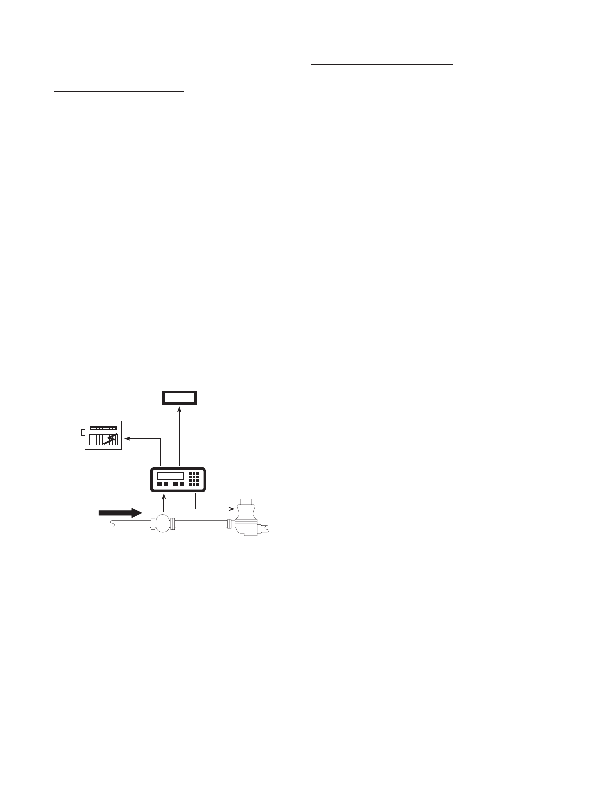
1-2 Typical Application
The above application involves liquid flow.
The start button is pushed and the DPF-310
receives pulses from the flowmeter. The pulses are scaled by the K Factor and sent out via
the pulsed output to an external counter. The
Analog output is directed to a strip chart recorder which gives a hardcopy of the rate. As
the Prewarn is reached, the control valve partially closes. When the final Preset is reached
the valve shuts down completely. At any time
the flow can be suspended by hitting the stop
button. Through the serial communications, a
computer keeps a record of the daily events.
Ratemeter
Accurate to 5 1/2 digits (±1 display digit).
The ratemeter can be programmed to accept almost any number of pulses per unit of
measurement, sample from 2 to 24 seconds
maximum, and auto range up to 6 digits of
significant information. The ratemeter with a
K Factor of 1 displays the rate of pulses per
second. Simply dial in the proper K Factor
to display in minutes, hours or other units of
measurement. Press the C button, while the
unit is displaying the batch, to display the rate;
‘R’ is displayed on the left side of the display.
K Factor
The K Factor is used to convert the input
pulses or analog input into workable units.
The 8 digit K Factor is a divider with a range
of 0.00011 to 99999999 (the decimal point
may be keyed into any position). Separate
K Factors may be entered into the count and
rate sections of the DPF-310. Thus, you may
batch in gallons and display rate in liters per
hour. The maximum factored count speed is
20000 Hz. The maximum factored rate is 7
digits.
16 Point Linearization (-LIN option)
This option extends the accurate range by allowing users to dial in different K Factors for
different input rates. This option may be used
with digital or analog inputs. (See Section 7-
3.)
1
Page 6

1-3 Principles of Operation (continued)
Counter
The maximum count is 99999999. In the
setup mode choose “RO” (Reset to Zero) for
adding (count up) operation or “SP” (Set to
Preset) for subtracting (count down) operation. At any time, the display can be made
to flash the Grand Total by pressing the ENT
button while in the run mode. Activating the
CLR button while the Grand Total is flashing,
resets the Grand Total counter.
Lockout
Unauthorized front panel changes can be prevented by entering a user selected, four digit
code, in the “Lockout” mode. The status of
the unit can be observed but “LOCK ON” appears if changes are attempted. Entering the
code again returns the unit to “LOCK OFF”
status.
Analog Output (-A option)
The Analog Output option is controlled by an
Open Collector transistor, it gives a 4 to 20mA
output which corresponds to predefined rate
or total readings. In the Setup mode the user
is prompted to set the low and high (4 to 20
mA) values and also decide if the analog signal will correspond to the ratemeter or totalizer.
Frequency out
The DPF-310 generates a pulse out for each
factored count. An NPN transistor output (Pin
2), can drive external devices at rates of 10,
200, 2000 or 20000 counts per second as selected through the keypad menu. If the K Factor scaled inputs generate pulses faster than
the output speed selected, an internal buffer
will store up to 9,999 counts before “DATALOST” flashes on the screen. This indicates
that the counts being totaled and the scaled
outputs may be incorrect. Note that all counts
stored in the internal buffer will be pulsed out
at the selected frequency even if the counter
is reset.
A sinking driver generates a linear current
across the user’s external device (such as a
strip chart recorder, PLC, computer, external
meter, etc). The DPF-310 can supply the 24
VDC to power the current loop. (Connect pin
15 to 13, Pin 16 is now +24 VDC with respect
to pin 12.) Connect Pin 16 to the + DC side of
the external device and connect Pin 3 to -DC
side of the external device.
2
Page 7

1-4 STD PRE and EZ PRE Operation Modes
STD PRE and EZ PRE Operation Modes
Version 8.7 of the DPF-310 software allows the user to choose between STD PRE (Standard
Preset) and EZ PRE (Easy Preset) operation modes. STD PRE operation is well suited for batch
amounts that do not change, since the program mode must be entered to change the preset and
the batch count must be cleared before starting a new batch. EZ PRE has been designed for users
who frequently change the batch amount. During EZ PRE operation, the preset can be viewed and
changed without entering the program mode and another batch can be started without resetting the
unit.
Note: Before a batch is started and after a batch is complete, the unit will continue to totalize all
inputs.
Note: EZ PRE is not available on units with 16 Point Linearization.
Using STD PRE
Programming
Select STD PRE - Go into the Program Mode and
select STD PRE in the PRE TYP sub menu.
Set the PRESET and PREWARN - Go into the
Program Mode and enter the desired values for
the PRESET and the PREWARN.
Program the Counter - Go into the Program
Mode and set up the counter in the COUNT sub
menu.
Operation
Start a Batch - In the Run Mode, reset the total by
pressing “CLR”, then press “A” to start. When
started, both relays energize and the counter
begins to count. When the batch is complete,
the relays drop out and the unit displays the
amount that was batched (0 if in Set to Preset
mode).
Stop a Batch - Press “B”, to temporarily stop
process by de-energizing the PRESET and
PREWARN relays. Press start, “A”, to continue
process.
Repeat a Batch - In the Run Mode, reset the total
and press the start button.
Change the Batch Size - Go to the Program
Mode and enter new PRESET and PREWARN
values.
Using EZ PRE
Programming
Select EZ PRE - Go into the Program Mode and
select EZ PRE in the PRE TYP sub menu.
Set the PRESET and PREWARN - Go into the
Program Mode and enter the desired values
for the PRESET and the PREWARN.
Program the Counter - Go into the Program
Mode and set up the counter in the COUNT
sub menu.
Operation
Start a Batch - In the Run Mode, press “A” to
start. When started, both relays energize and
the counter begins to total. When complete,
the relays drop out and the display flashes the
current PRESET value.
Stop a Batch - Press “B”, to temporarily stop
process by de-energizing the PRESET and
PREWARN relays. Press start, “A”, to continue
process.
Repeat a Batch - Press the start button.
Change the Batch Size - With the current
PRESET flashing on the display, type a
new number using the keypad. This number
becomes the PRESET.
Display Batch Total or Rate - With the current
PRESET flashing, press “ENT” to place the
PRESET value in memory and use the “C”
button to toggle between the Batch Total and
the Rate.
3
Page 8

1-5 Specifications
Housing:
High impact plastic case with NEMA 4X front
panel.
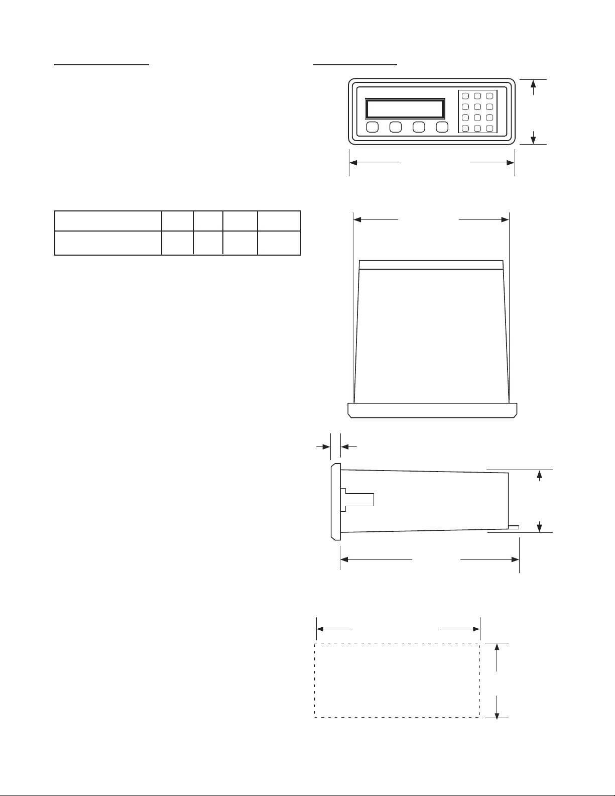
Dimensions:
See Section 1-5, Page 4.
Display:
8 Digit, 0.55” High, 15 Segment, Red Orange,
LED.
Input Power:
A: 110 VAC ± 15% or 12 to 27 VDC
B: 220 VAC ± 15% or 12 to 27 VDC
NOTE: AC Inputs are internally fused with a
160mA slow blow fuse.
Current:
Maximum 280 mA DC or 5.3 VA at rated AC
voltage.
Output Power:
(On AC powered units only): +12 VDC at 100
mA. Separate Isolated 12 VDC at 100 mA to
allow ± 12 VDC or +24 VDC, regulated ± 5%
worst case.
Temperature:
Operating: +32°F (0° C) to +130 ° F (+54° C)
Storage: -40°F (-40° C) to +200 ° F (+93° C)
(Extended operating temperature range
available, consult factory)
Reset
Front push button: “CLR” resets displayed
number and control output.
Remote Input (Terminal 5): Open or 0 to 1
VDC (low), 3 to 30 VDC (high), 10K ohm input
impedance to ground. Minimum pulse on /
off time 5 msec.
Accuracy over full temperature range:
Analog - Zero error: ±0.175% full scale max.
Overall error: ±0.5% full scale max.
Digital - 100% (within specified voltage
ranges)
Pulse Inputs (DPF-311):
Sourcing (standard): High impedance pulse
input. Open or 0 to 1 VDC (low), 3 to 30 VDC
(high), 10K ohm input impedance. 20 KHz
maximum speed (min. on / off 25 usec).
Sinking (dip switch selectable): Same as
above with 4.7 K ohm pull up resistor to +5
VDC with respect to Terminal 12.
Analog Inputs (DPF-312):
The 4-20mA current is converted to a highly linear 0 to 10 KHz frequency. This frequency can
then be scaled by 8 digit K-factors to display rate
or count in the appropriate engineering units.
Input Range: 4-20 mA
Input impedance: 250 Ω
Memory:
EEPROM stores all program, display mode
and count data for a minimum of 10 years if
power is lost.
4
Page 9
1-5 Specifications (continued)
PANEL
CUTOUT
2.50 -0, +0.02
(63.5 -0, +0.5)
7.375 -0, +0.04
(187.3 -0, +1)
7.375
(187.3)
(NOM.)
0.53
(13.5)
6.0
(152.4)
2.48
(63)
(NOM.)
(NOM.)
A B C D
1 2 3
4 5 6
7 8 9
CLR0SET
8.17
(207.5)
3.31
(84)
Factored Output:
One pulse per each factored count
Sinking (NPN Transistor)
Open Collector sinks 250 mA maximum to 1
volt maximum from 30 VDC maximum
Internal buffer: 9999 pulses
Output speed: user selectable (see table
below)
Speed (Hz) 10 200 2000 20000
Min. on/off (msec) 47.5 2.0 0.2 0.013
Analog output (-A option):
4-20 mA
Sinking, (NPN transistor), Open Collector
Compliance voltage: 3-24 VDC, non-inductive
Accuracy: ±100 uA worst case
Update Rate: Follows ratemeter
Control Outputs:
SPDT Relays
Contact rating: 10 A 120/240 VAC or 28 VDC.
1-6 Dimensions
All Dimensions in inches (mm)
5
Page 10

1-5 Dimensions (continued)
SECTION 2 INSTALLATION
2-1 Receipt of Equipment
When the equipment is received, the outside
packing case should be checked for damage
incurred during shipment. If the packing case
is damaged, the local carrier should be notified
at once regarding his liability. A report should
be submitted to the factory.
Carefully remove the equipment from the packing case and inspect for damaged or missing
parts.
2-2 Return Shipment
Do not return assembly or part without an
Authorization Return number (AR). The AR is
obtained by calling Omega customer service.
2-3 Panel Mounting
The controller should be located in an area with
a clean, dry atmosphere which is relatively free
of shock and vibration. The DPF-310 is installed
in a 7.365” (187 mm) wide by 2.495” (63.4 mm)
high panel cutout. To mount the controller proceed as follows:
a. Prepare the panel opening.
b. Slip the gasket (provided) over the rear of
the counter case and slide it forward until it
engages the inner surface of the front bezel.
c. Install the screws (provided) in the mounting
brackets and insert in the holes located on
both sides of the DPF-310.
d. Tighten the screws firmly to attach the coun-
ter bezel to the panel.
Full Size Panel Cutout Template
(copy before using)
2-4 Electrical Connections (Reference Figures
2-1 to 2-3)
All connections are completed at terminal blocks
located at the rear of the case. Make sure all
power is disconnected before making any electrical connections. In cases where cables are
situated in areas with heavy electrical fields,
6
Page 11
2-4 Electrical Connections (continued)
&,/7-%4%2
3()%,$
'2/5.$
3)'.!,
4"
!-0,)&)%2
4"
)NPUT!
'ROUND$#
6OLTS/UT
)SOLATE6OLTS
)SOLATE6OLTS
!#)N
!#)N
6$#
'2/5.$
6! # &53%
(Z
!
&,/7-%4%2
!.!,/'3)'.!,
)NPUT!
'ROUND$#
6OLTS/UT
)SOLATE6OLTS
)SOLATE6OLTS
!#)N
!#)N
6$#
6! # &53%
(Z
shielding is required for maximum noise immunity. One end of the shielding should be
connected to earth ground. Relays or inductive coils connected to or located in the immediate area should be arc suppressed with appropriate diodes, MOV’s or resistor capacitor
networks.
Caution: An external fuse is required:
DC Power: 0.5 Amp
AC Power: 0.125 Amp
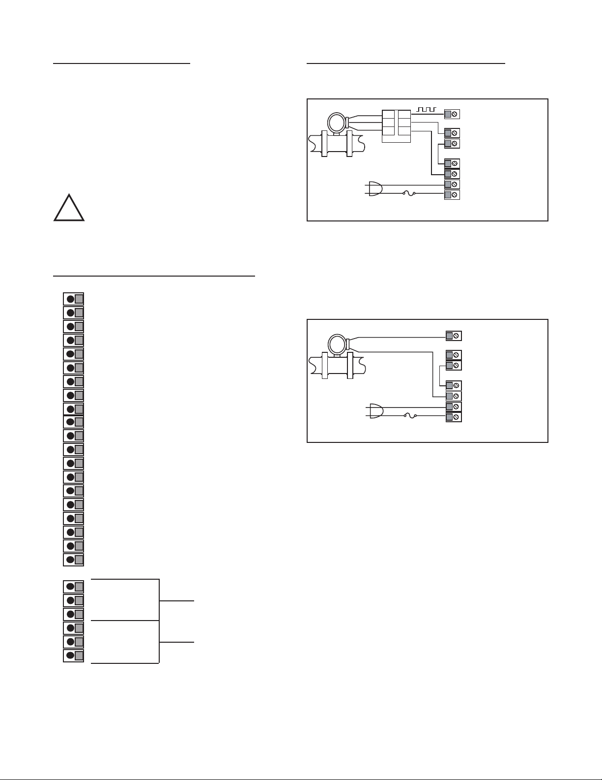
2-5 Wiring Connections and Diagrams
1 - Not Used
2 - Scaled Pulse Output O.C.
3 - Analog Output (optional)
4 - Input A (Pulse/Analog)
5 - Remote Stop/Reset Input
6 - Not Used
7 - Not Used
8 - Not Used
9 - Not Used
10 - Remote Start Input
11 - Ground (-DC), Input Common
12 - Ground (-DC), Input Common
13 - +12 Volts Out
14 - DC Power In (12 - 27 VDC)
15 - Isolate -12 Volts
16 - Isolate +12 Volts
17 - AC In
18 - AC In
19-Prewarn Transistor O.C.
20-Preset Transistor O.C.
2-5 Wiring Connections and Diagrams
Figure 2-2
Typical Digital Wiring Connections
Figure 2-3
Typical Analog Wiring Connections
R1-N.O
R2-N.C. Preset
R3-Common
R4-N.O
R5-N.C. Prewarn
R6-Common
Figure 2-1 Terminal Block Connections
7
Page 12
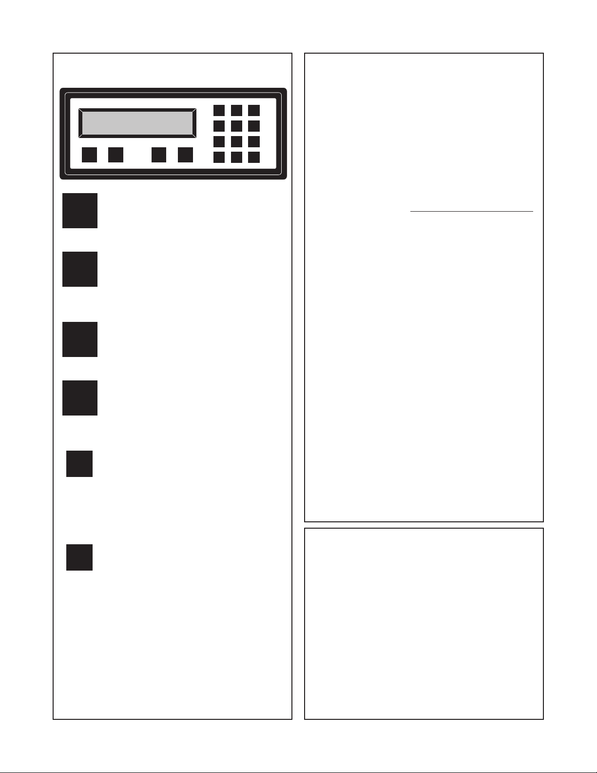
3-1 Front Panel Operation
STOP
D
START
RATE/TOTAL
MENU
CBA
ENT
0
7
4
1
2
3
6
5
8
9
CLR
START - Pressing “A”, starts the
A
process by energizing the PRESET and
PREWARN relays. Press “CLR” to reset
Batch Total before starting new batch.
Weighted Averaging
Version 8.7 of the DPF-310 software includes
weighted averaging of the rate display. Weighted
averaging is not available on units with 16 Point
Linearization.
Weighted averaging can be used to create a more
stable display when the rate input is fluctuating.
A weight, “W”, from 00 to 99 is applied to the old
rate data before the new rate data is sent to the
display. The following equation is used:
Rate Display =
W = Weight (00-99)
(Old Data x W + New Data)
(W + 1)
B
C
D
ENT
CLR
STOP - Pressing “B”, will temporarily
stop the process by de-energizing the
PRESET and PREWARN relays. Use
START to continue the process from
where it stopped.
RATE/TOTAL - Pressing “C” toggles
between rate and total count displays.
The rate display has an “R” on the left
side of the screen.
MENU - Pressing “D” takes the unit out of
the Run Mode and into the Programming
Mode (See Programming, Page 43 and
45). “D” is also used make to some
programming selections.
ENT - With Count showing in the Run
Mode, pressing “ENT” displays the
Grand Total, which begins flashing on
the screen. Press “ENT” again to return
to the Count. In the Programming Mode,
“ENT” is used to accept a selection (See
Programming, Page 43 and 45).
CLR - When the count total is displayed,
pressing “CLR” will reset the counter to 0
or to Preset A depending on how it was
programmed. When the Grand Total is
displayed, pressing “CLR” will reset it to
0. When the Preset or Program Mode
values are displayed, pressing “CLR” will
reset them to 0, so that new values can
be entered.
If a weight of 00 is used, the new rate data will
go directly to the display without being averaged.
If a number other than 00 is entered for the
weight, then the new data will be averaged with
the old data before being sent to the display.
Higher weight numbers will create a more stable
rate display. Small rate changes will be more
noticeable when lower weight numbers are used.
Programming Weighted Averaging
1. In the Program Mode, got to the RATE sub menu
and program the K-FACTOR, the WINDOW, and
the SIG FIG parameters.
2. When the display shows WEIGHTXX (XX
represents the current WEIGHT value), either
accept the current value and return to the Run
Mode by pressing “ENT” or clear the current value
by pressing “CLR”.
3. If the current value was cleared, the display
shows WEIGHT00. Using the keypad, enter a
new WEIGHT value from 00 to 99. Press “ENT” to
accept the new value and return to the Run Mode.
Remote Start, Stop, and Reset
(not available on DPF-312-A)
A 4 to 30 VDC positive pulse will activate these
inputs.
START (Pin 10): When activated, the unit will
START as described in Front Panel Operation.
STOP/RESET (Pin 5): When activated, the unit will
STOP (If the unit is started and the batch is not
complete). A second pulse to pin 5 will reset the
counter (When the unit is stopped or when the
batch is complete). If pin 5 is held high (4 to 30
VDC), the display will flash “STOPPED” and any
start inputs will be inhibited.
8
Page 13

3-2 VER 8.8 Programming
Overview:
This Section of the manual provides an outline of
programming procedures for the DPF-310 software
version 8.7. Detailed descriptions and programming
instructions for this unit are available in previous
sections of this manual. Page number references are
included to help you find related information in this
manual.
Programming Procedures:
Enter Program Mode - Press the MENU button,
“D”, in the Run Mode.
Choosing a Sub Menu - Once in the Program
Mode, continue pressing the “D” button until the
desired Sub Menu is displayed. Press “ENT” to
enter the selected Sub Menu.
Making a Selection - An arrow, “↓”, appearing over
only the “D” button indicates that “D” is used to
change the selection. When an arrow appears
over “B” and “D”, one must be selected.
Entering a Value - The keypad is used to enter a
number. Use the “D” button to enter a decimal.
(Ex: 34.5 would be entered by pressing “3”, “4”,
“D”, and “5”)
Accept a Value or Selection - Press “ENT” to ac-
cept the value and go to next step.
Exit Program Mode - Program or skip each step
of one of the menus to return to the Run Mode.
Pressing “ENT” allows a step to be skipped without changing its value.
Key to Programming Flow Chart:
■
Display - This box represents the unit’s dis-
play. In the Run Mode, the flow rate, the batch
total, or the grand total will be displayed.
XX Current Value - The number that is currently
programmed for that step. It must be cleared
(CLR button) before entering a new value.
00 No Value - Indicates that programmed value
for that step has been cleared, and a new
number may be entered.
Keypad - Use the front panel keypad to enter
a value or select a decimal point location for
this step.
3-3 VER 8.8 K-Factor Programming
(See Programming Flow Chart, Page 10)
The average sensor K-Factor is usually provided in
pulses per unit volume, and will have to be modified
before entering it into the instrument. On most flowmeters, the average sensor K-Factor is stamped
on the nameplate or provided on its documentation. (see section 7 for Calculating K-Factors, for a
complete example)
Count K-Factor:
The Count K-Factor must be modified to allow for
the decimal point location chosen in the ”DEC LOC“
step.
Sensor K-Factor
DPF
DPF - The Decimal Point Factor is a divider to compensate for the displayed decimal point.
DPF Table
DPF Decimal
1 XXXXXX.
10 XXXXX.X
100 XXXX.XX
1000 XXX.XXX
10000 XX.XXXX
100000 X.XXXXX
Rate K-Factor:
The Rate K-Factor must be determined to dis-
play the rate in the desired time unit. The floating
decimal point displayed by the Rate Meter floats
according to the significant figure setting used in
the SIG FIG step.
Sensor K-Factor
Where:
TF - The Time Factor is a divider to adjust the
time units that the Rate Meter shows.
TF Table
TF Time Units Rate Display
1 Seconds Units per Second
60 Minutes Units per Minute
3600 Hours Units per Hour
86400 Days Units per Day
(For information on entering a K-Factor on a unit
with 16 Point Linearization (-LIN option), see 16
Point Linearization Notes, page 11)
= Count K-Factor
= Rate K-Factor
TF
9
Page 14
4.%
$
%4!2
n
$
4.%
2/4#!&+
8888
2,#
887/$.)7
2,#
88')&')3
2,#
884(')%7
45/+#/,
n
4.%
$
8825#%3
2,#
%$/#
8888
2,#
45/',!
n
1%2&45/
n
4.%
$
4.%
$
$
42',.!
n
4#',.!
n
4.%
7/,4%3
8888
2,#
(')(4%3
$
n
n
4.%
n
n
4.%
7/$.)7
4.%
')&')3
4.%
25#%3
4.%
4.%
4.5/#
n
4.%
$
2/4#!&+
8888
2,#
2 n 03 n
4.%
$
"
#/,#%$
4.%
4.%
4%3%20
n
4.%
$
8888
2,#
.2!7%20
n
$
8888
2,#
4.%
094%20
n
4.%
$
$
%20:%
n
%20$43
n
4.%
4.%
4.%
5.%-
$
EDO-NU2
TRAH#WOL&GNIMMARGOR0NOISRE6ERAWTFO3
NOITAREPOCISABROFDEMMARGORPEBTSUMETA2EHTRODNATNUO#EHTNOITAZIRAENI,TNIO0TUOHTI7TINUDRADNAT3AN/
REBMU.LEDO-KCEH#TINUEHTNIDEDULCNIEBTONYAMERUTAEFTUBRAEPPASYAWLALLIWUNEMBU3e
EGA0
e EGA0
EGA0
EGA0
EGA0
EGA0
EGA0
EGA0
$2!#45/
n
2,#
8888
2,#
4(')%7
4.%
4.%
4.%
4
10
Page 15

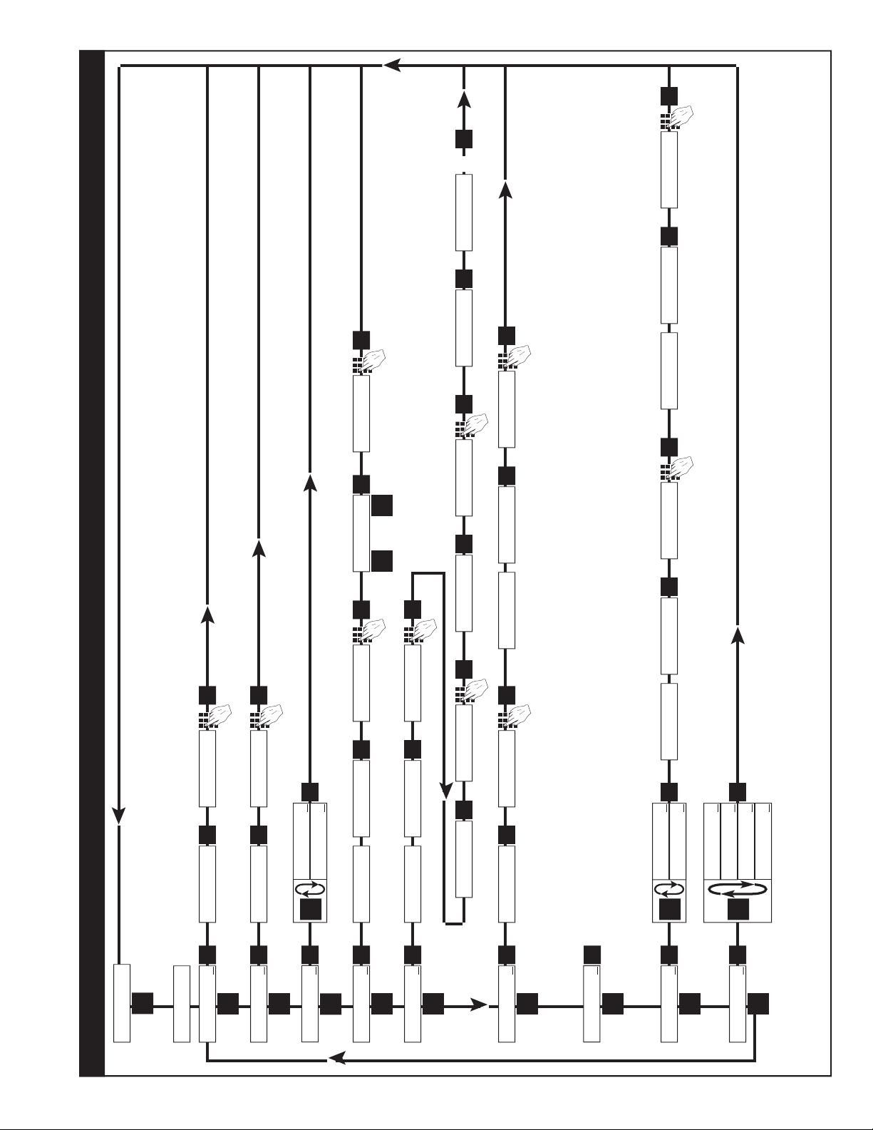
3-5 VER 12.0 Programming
Unit with 16 Point Linearization (-LIN option)
Overview:
This Section of the manual provides an outline
of programming procedures for the software version 12.0. Detailed descriptions and programming
instructions for this unit are available in the following
sections of this manual. Page number references
are included to help you find related information in
this manual.
Programming Procedures:
Enter Program Mode - Press the MENU button,
“D”, in the Run Mode.
Choosing a Sub Menu - Once in the Program
Mode, continue pressing the “D” button until the
desired Sub Menu is displayed. Press “ENT” to
enter the selected Sub Menu.
Making a Selection - An arrow, “↓”, appearing over
only the “D” button indicates that “D” is used to
change the selection. When an arrow appears
over “B” and “D”, one must be selected.
Entering a Value - The keypad is used to enter a
number. Use the “D” button to enter a decimal.
(Ex: 34.5 would be entered by pressing “3”, “4”,
“D”, and “5”)
Accept a Value or Selection - Press “ENT” to ac-
cept the value and go to next step.
Exit Program Mode - Program or skip each step
of one of the menus to return to the Run Mode.
Pressing “ENT” allows a step to be skipped without changing its value. (Note: “B” or “D” must be
pressed on the first step in the DEV TYP menu)
3-6 VER 12.0 16 Point Linearization (-LIN
option) Notes
(See Programming Flow Chart, Page 12)
A K-Factor and a Frequency must be entered for at
least three points on a unit with Linearization.
Linearization K-Factor: The K-Factor for each
Linearization point must be modified to allow for the
display decimal point location chosen in the “DEC
LOC” step of the “DEV TYP” menu. Modify each
K-Factor using the following equation:
K-Factor
DPF
DPF - The Decimal Point Factor is a divider to
compensate for the displayed decimal point.
= Linearization K-Factor
DPF Table
Desired Total
Decimal Location: DPF
XXXXXX. 1
XXXXX.X 10
XXXX.XX 100
XXX.XXX 1000
XX.XXXX 10000
X.XXXXX 100000
Example: for X.X, DPF = 10
Calculating K-Factors and Frequencies: If a
Linearization table is not available, the K-Factor
and the frequency for each point can be calculated
using the Test Mode on the unit. Refer to Section 7-
3.2, Test Mode Operation and K-Factor Calculation,
on page 37.
Key to Programming Flow Chart:
■
Display - This box represents the unit’s dis-
play. In the Run Mode, the flow rate, the batch
total, or the grand total will be displayed.
XX Current Value - The number that is currently
programmed for that step. It must be cleared
(CLR button) before entering a new value.
00 No Value - Indicates that programmed value
for that step has been cleared, and a new
number may be entered.
Keypad - Use the front panel keypad to enter
a value or select a decimal point location for
this step.
Entering K-Factors and Frequencies: Refer to
Section 7-3, Calculating 16 Point K-Factors, on
page 37 and the programming step listing on page
25.
11
Page 16

12
$2!#45/
n
%
$
45/+#/,
n
4.%
$
45/',!
n
1%2&45/
n
4.%
$
4.%
$
$
42',.!n4#',.!
n
4.%
7/,4%3
8888
2,#
(')(4%3
8888
2,#
$
n
n
4.%
n
n
4.%
4.%
4%3%20
n
4.%
$
8888
2,#
.2!7%20
n
$
8888
2,#
4.%
0946%$
n
4.%
$
4.%
4.%
5.%-
$
EDO-NU2
TRAH#WOL&GNIMMARGOR0NOITAZIRAENI,TNIO0NOISRE6ERAWTFO3
42 n 4.# n
2 n 03 n
4.%
$
"
#/,#%$
4.%
$
"
887/$.)7
2,#
88')&')3
2,#
7/$.)7
4.%
')&')3
4.%
4.)/0
n
4.%
$
$
3%45.)-
n
325/(
n
4.%
3$./#%3
n
43%4
n
4.)/0
4.)/0
4.%
88&
2,#
&
4.%
88+
2,#
+
4.%
4.%
2,#
TIX%O4
CT%4.)/04.)/0X%TNIOPTXENOTTNEMERCN)
SNOITAREPOCISABROFDEMMARGORPEBTSUMUNEMBUSNOITAZIRAENI,TNIO0EHTNISTNIOPEERHTTSAELT!
TNIOPTAHTOTPUDERETNEATADLLAPEEPUTTESTNIO0EHTTIXEOTTNIOPYNATAvhFOTNIO0ARETN%
REBMU.LEDO-KCEH#TINUEHTNIDEDULCNIEBTONYAMERUTAEFTUBRAEPPASYAWLALLIWUNEMBU3e
%$/#
8888
2,#
4.%
12
Page 17

3-8 How to Program
The initial programming of the unit is accomplished by first depressing the MENU button.
After pressing the MENU button once, the
display will read preset. To cycle to the next
control parameter option, merely press the
MENU button and Prewarn will appear on the
display. If the user does not wish to choose
this section of the menu, depress MENU button again and the next control or parameter
will appear.
Selection of all MENU control parameters is
accomplished through the routine described
for Preset.
3-9 Frequently Asked Questions About
Setting Up The DPF-310
Q. Is there any way to backspace if the wrong
button is hit by accident?
A. No, you can depress the CLR button and
start entering the number all over again or
press ENT repeatedly until back in the Run
mode and start over again from there.
Q. Is there any way to put a decimal point in a
number such as a preset or K Factor?
A. Yes, simply press the D button after the
digit that you would like the decimal point.
It will appear to the right of the digit.
The following is the sequence for entering a
Preset quantity.
1. Depress the Menu D button once. The
display will read MENU. After a one second pause the display will read PRESET.
2. Depress the Enter ENT button; the display will flash indicating that you are not in
the Run Mode and not displaying the current batch total.
3. If the batch size is satisfactory, depress
the ENT button. This value will be entered
into memory. Simultaneously, the unit will
return to the Run Mode.
4. To change the preset value, depress the
CLR button and enter new number. Example: Suppose “250” is the new batch
size. Press CLR, then 2 , then 5 , then 0 .
When the display holds the desired value,
depress the ENT button. The new batch
size will be stored in memory and simultaneously the DPF-310 will return to the Run
Mode.
Q. Is there any way to enter a negative number
for one of the Presets or K Factors?
A. No, negative values are not allowed.
Q. Is there any way to ruin the unit or completely
erase it by entering a bad number?
A. No, if a number or entry is not valid the unit
will ignore it or flash an error message.
Q. If the unit does not have serial communica-
tions or analog out, does the OUTCARD and
ALG OUT sections of the menu still have to
be set up?
A. No, there are default settings from the fac-
tory already in the unit. No setup of these
menu items is necessary for normal operation.
Q. Does the DPF-310 have to be told what type
of input it has connected to it?
A. No, The input signals are conditioned in
hardware. This allows the input cards to
be interchanged without modifying the software.
Q. If CLR is not pressed, numbers can still be
written over the Presets or K Factors. Will
these numbers be accepted if the ENT button is pushed?
A. No, in order for a Preset or K Factor to be
changed, the old number must be cleared
out first by depressing the CLR button.
13
Page 18

3-10 Setup Procedure
D
CLR
ENT
1 2 3 4
ENT
D
D
ENT
CLR
1 2 3 4
ENT
MENU ITEM 1 PRESET
PRESS DISPLAY
PRESET ↓
Menu Button.
Flashing PRESET number.
Enters Preset Routine.
0 Flashes.
Clears out existing PRESET.
1234 PRESET Flashes.
Sample Preset.
Last count, unit now in run mode.
Store new Preset.
Final Preset is Set.
MENU ITEM 2 PREWARN
The Prewarn value is the amount before the Preset value that the Prewarn relay will deactivate. For example, if
you want the Prewarn relay to drop out 10 counts before the Preset and your Preset is 1234, then set your Prewarn
at 10 (not at 1224). Enter a Prewarn of “0” for the Prewarn and Preset relays to activate together. To disable the
Prewarn relay, enter the same value for Preset and Prewarn.
PRESS DISPLAY
PRESET ↓
MENU Button.
PREWARN ↓
Flashing PREWARN number.
Enters Prewarn Routine.
0 Flashes.
Clears out existing PREWARN.
1234 Prewarn Flashes.
Sample Prewarn.
Last count, unit now in Run Mode.
The Prewarn is Set.
Note: Remember, if the prewarn is a larger number than the preset, then the warning “PREWRONG” will flash on
Store new Prewarn.
the display. Enter a prewarn value that is less than or equal to the preset to clear this warning.
14
Page 19

3-10 Setup Procedure (continued)
DDD
ENT
ENT
DDD
ENT
D
CLR
3 7 D 6
MENU ITEM 3 PRE TYP
This menu item is used to set up the Preset Type.
PRESS DISPLAY
PRESET ↓
PREWARN ↓
PRE TYP ↓
STD PRE ↓ EZ PRE↓
Press D toggle between selections.
Enters displyed selection Run Mode
The PRE TYP is Set.
MENU ITEM 4 COUNT
Setting the Counter
PRESS DISPLAY
PRESET ↓
PREWARN ↓
PRE TYP ↓
COUNT↓
K FACTOR
K FACTOR flashes then shows the current K Factor.
Note: The K Factor setup is skipped if the unit has 16 Point option. The unit goes directly to R0 SP.
0 Flashes.
Clears out existing K FACTOR.
37.6 Flashes.
Sample K Factor, or enter calculated value from notes or worksheet.
continued on next page
15
Page 20

3-10 Setup Procedure (continued)
ENT
B
B
B
B
D
ENT
ENT
MENU ITEM 4 COUNT (continued)
PRESS DISPLAY
R0 ↓ SP ↓
Store new K Factor.
RO is Reset to zero. SP is Reset to Preset. This selection determines whether the unit
counts up or counts down. If RO is selected ( B is pressed), the unit will count in the “up”
direction towards the Preset (dropping out the Prewarn, if passed). If SP is selected ( D
is pressed), the unit starts at the Preset and counts “down” towards zero (dropping out
the Prewarn at its set value.)
or Selects by moving the cursor under the
arrow by R0 or SP
DEC LOC
Store R0 or SP.
DEC LOC allows the user to choose where the decimal point will be located when
the Batch Count or Grand Total are displayed. The decimal point is for display only
and does not affect K Factors. (The K Factor must be scaled to reflect the DEC LOC,
see Section 7 for calculating the K Factors) Simply press the keypad numbers to move
the decimal point. Only one decimal point can be displayed, multiple decimal points are
not available. Pressing 0 turns off the decimal point.
DEC LOC
As an example, the decimal point will move to the right of the fourth digit from the right
(displays units and thousandths).
Run Mode.
Store new DEC LOC.
The Counter portion of the DPF-310 is now set up.
16
Page 21

3-10 Setup Procedure (continued)
DDD
ENT
D
CLR
D
1 2 D 0 5 6
ENT
CLR
MENU ITEM 5 RATE
Setting the Ratemeter
PRESS DISPLAY
PRESET ↓
PREWARN ↓
PRE TYP ↓
COUNT↓
RATE↓
K FACTOR
This selects the Ratemeter portion of the menu.
K FACTOR flashes then shows the current Ratemeter K Factor.
Note: The K Factor setup is skipped if the unit has 16 Point option. The unit goes directly to WINDOW.
0 Flashes.
Clears out existing K FACTOR.
12.056 Flashes.
Sample K Factor, or enter calculated value from notes or worksheet.
WINDOW ##
Store new K Factor.
Normally the ratemeter updates each second. If no signal comes in during that time, the
ratemeter will wait until the window times out or a signal comes in; the display will not update. The window is the maximum sample time, in seconds, on which the waiting period
is based. The range is from 02 to 24 seconds.
WINDOW 00
Clears out existing WINDOW number value.
WINDOW 05
As an example, extends the window to 5 seconds.
continued on next page
17
Page 22

3-10 Setup Procedure (continued)
CLR
ENT
ENT
CLR
ENT
MENU ITEM 6 RATE (continued from previous page)
From the previous page, we are in the SIG FIG setting portion of the Ratemeter setup Menu.
PRESS DISPLAY
SIG FIG ##
Store new WINDOW.
SIG FIG indicates how many meaningful digits are shown. For example, if SIG FIG
is set at three; a rate of 24737.89 will be displayed as 24700; a rate of 0.739216 will be
displayed as 0.739. Note that trailing zeroes will be inserted only if necessary. Digits
beyond the SIG FIG value are truncated and zeroes are inserted as needed, no rounding is done.
SIG FIG 00
Clears out existing SIG FIG number value.
SIG FIG 04
As an example, display will show 4 significant figures.
WEIGHT##
Store new SIG FIG.
WEIGHT is an averaging factor. Higher settings provide more averaging for a more
stable rate display. Derived from:
(OLD DATA • “WEIGHT” + NEW DATA)
(“WEIGHT + 1)
WEIGHT 00
Clears out existing WEIGHT value.
WEIGHT04
As an example,
RUN MODE
The Ratemeter portion of the DPF-310 is now setup.
18
Page 23

3-10 Setup Procedure (continued)
DDD
ENT
CLR
D
MENU ITEM 6 LOCKOUT
This menu item uses a 4 digit security code to prevent unwanted changes in the programming
or improper use of the DPF-310. The unit is shipped from the factory with a security setting of
00 and a lockout code of 1000.
Security example: First set the security shut down time in the Lockout menu then go to the
Run Mode. Press the START button. The word STARTED should briefly appear. If no signal
comes in before the security time is reached, the unit locks and displays SECURITY. Once the
unit locks all buttons except 0 thru 9 are disabled. To unlock the unit simply press in the lockout code. When the unit is unlocked all menu features are available for change.
Lockout example: To lock the unit, first make sure it is in the Run Mode, then press 1 - 0 - 0 -
0. The words LOCK ON should briefly appear. Once the unit is locked:
a. Preset can still be accessed and changed.
b. Prewarn can still be accessed but cannot be changed.
c. the rest of the menu cannot be accessed.
To unlock the unit simply press 1 - 0 - 0 - 0. The words LOCK OFF will appear briefly. When
the unit is unlocked all menu features are available for change.
To put in a different security time or lockout code follow this setup procedure.
PRESS DISPLAY
PRESET ↓
PREWARN ↓
DEV TYP ↓
LOCKOUT ↓
SECUR ##
SECUR is the time, in seconds, that the unit will wait between pulses or for a
signal to come in once STARTED. For example: The SECUR is set at 15, in run
mode the START button is pressed. If at any time the unit does not receive a signal for
15 seconds the display will go to security and the unit will lock itself. The unit retains
elapsed security time if STOPPED before security times out. When restarted, the unit
resumes security timing from where it left off. As soon as a signal comes in the security
time is reset. Entering a security time of 00 disables the security feature.
SECUR 00
Clears out existing security time.
SECUR 34
As an example, unit waits 34 seconds before Security Mode.
Continued on next page
19
Page 24

3-10 Setup Procedure (continued)
ENT
CLR
1 2 3 4
ENT
1 2 3 4
1 2 3 4
From the previous page, we are in the CODE setting portion of the Lockout setup Menu.
PRESS DISPLAY
CODE
Store new security time.
Enters device routine to program in a 4 digit Lockout Code. The word CODE appears
briefly then the current Lockout Code number is displayed.
0 Flashes.
Clears out existing Lockout Code.
1234 Flashes.
Sample Lockout Code, or enter desired value from notes or worksheet.
Be sure to record any changes in the lockout code in case it is forgotten!
Last count, unit now in Run Mode.
Store new LOCKOUT Code. (Sample tryout below.)
LOCK ON
Enter the sample / new value . . . the unit is now locked!
LOCK OFF
Enter the sample / new value. . . the unit is now unlocked!
The lockout procedure is finished.
20
Page 25

3-10 Setup Procedure (continued)
DDDDD
ENTDENT
D
CLR
1 7 5 D 5
ENT
MENU ITEM 8 ALG OUT (-A option)
This section is for models of the DPF-310 with the analog output feature. The Analog Output
card is a 4 - 20 mA current sink. The low (0mA) or (4 mA) and high (20mA) settings may be
set at any range. Attempting to set the high setting lower than or the same as the low setting
will display the warning message HIGH ≤ LOW and send the unit back to the low setting section of the routine. The unit will not exit the ALG OUT routine until a proper setting has been
entered. If the displayed rate is below the 4 mA setting, the current driver will stay at 4 mA.
This allows for offsetting the low end of the output signal. If the displayed rate exceeds the 20
mA setting the current driver will stay at 20 mA.
Note: The current sink follows (tracks) the display.
The Analog Output option is not available on Square Law Analog Input units.
PRESS DISPLAY
PRESET ↓
PREWARN ↓
DEV TYP ↓
LOCKOUT ↓
OUTCARD ↓
ALG OUT ↓
ANLG RT ↓
The analog output may correspond to the ratemeter or the totalizer. At this point, the
selection is made by pressing ENT on the appropriate prompt. ANLG RT is the prompt
for the rate meter. ANLG CT is the prompt for the batch totalizer.
ANLG CT ↓
Press D to toggle between selections.
SET LOW
Enters the routine for setting up the Analog Output card.
SET LOW flashes then shows the 4 mA Setpoint value.
0 Flashes.
Clears out existing Low Setpoint value.
175.5 Flashes.
Sample Low Setpoint, or enter value from notes or worksheet. (D for decimal point.)
SET HIGH
Low Setpoint is stored. SET HIGH flashes then shows the 20 mA Setpoint value.
Continued on next page.
21
Page 26

3-10 Setup Procedure (continued)
CLR
ENT
6 7 5 9 D 5
DDD
ENT
DDD
ENT
From the previous page, we are in the SET HIGH setting portion of the ALG OUT setup Menu.
PRESS DISPLAY
0 Flashes.
Clears out existing High Setpoint value.
6759.5 Flashes.
Sample High Setpoint, or enter value from notes or worksheet. (D for decimal point.)
If High Setpoint is too low, the warning HIGH≤LOW will be displayed and the unit will
return to the SET LOW routine.
Last count, unit now in Run Mode.
High Setpoint is stored.
Analog Output is set.
MENU ITEM 9 OUT FREQ
All models of the DPF-310 have a pulse generator built in to them. This Output Frequency
generator sends pulses out which are scaled relative to the input signal via the counter K
Factor. This means that for every time the counter increments a pulse is available at the output.
Various output frequencies are available to the user for driving external devices. In case the rate
exceeds the output frequency selected, a 9999 pulse buffer is provided to hold the excess pulses.
If the buffer is completely filled the warning message DATALOST will flash on the display.
PRESS DISPLAY
PRESET ↓
D PREWARN ↓
Press until . . . OUT FREQ ↓
20000 ↓
Enters the routine for setting up the Frequency Output.
The display shows the last Frequency selection.
2000 ↓
200 ↓
10 ↓
Press D to go to 20000 ↓
Press ENT at desired Frequency.
Last count unit now in Run Mode.
Pulse Output is now set.
22
Page 27

3-10 Setup Procedure (continued)
DDD
ENT
DDD
ENT
MENU ITEM 10 16 POINT (-LIN option)
This section is for models of the DPF-310 which have 16 Point Linearization. This option al-
lows the user to key in from 3 to 16 different frequency points (inputs per second) and
assign different K Factors dividers from 0.00011 to 999999 for each of these frequencies.
Please refer to the K Factor worksheets (Section 7) or other notes you may have prepared.
PRESS DISPLAY
PRESET ↓
PREWARN ↓
Press until . . . 16 POINT ↓
SECONDS ↓
MINUTES ↓
HOURS ↓
The unit calculates the base rate per second from the incoming frequency and the specified K Factor. The rate can then be displayed in 3 ways:
SECONDS: The base rate.
MINUTES: The base rate times 60.
HOURS: The base rate times 3600.
TEST ↓
TEST is used to help set up the points and K Factors. In this mode the K Factor is automatically set to (1) one for both rate and total for all 16 points. Further information on
this mode can be found in Section 7-3 of this manual.
POINT 00
Press ENT on desired rate display. The unit now enters the Frequency and K Factor
setup mode.
To escape from this mode, press ENT when POINT 00 is being displayed.
Enter any other point from 1 to 16 via the front keypad and press ENT to continue.
Note: If the point number entered is greater than 16, the unit will default back to point
16.
Continued on next page.
23
Page 28

3-10 Setup Procedure (continued)
1 2 3 4
ENT
ENT
CLR
CLR
1 0 0 0
ENT
CLR
1 0 0 0
ENT
CLR
ENT
From the previous page, we are in the POINT setting portion of the 16 Point setup
Menu.
PRESS DISPLAY
then
POINT 01
F 1
The unit displays the last frequency entered for Point 01.
F 0
Clears out existing frequency for Point 01.
F 100
Sample frequency, or enter desired value from worksheets.
K 1
The unit displays the last K Factor entered for Point 01.
K 0
Clears out existing K Factor for Point 01.
K 10
Sample K Factor, or enter desired value from worksheets.
POINT 02
The above procedure is now repeated for Point 02. The setup continues in this manner
until up to 16 points are entered.
Note: A minimum of (3) three points must be entered. All frequencies of consecutive point
numbers must be entered in ascending order, beginning with 0 for the first point.
Please read Section 7-3 for all rules concerning 16 Point Frequency and K Factor entry.
PRESS DISPLAY
POINT 00
Clears Point number in preparation for exit of 16 Point setup routine.
Last count, unit now in Run Mode.
Press ENT on Point 00 to exit 16 Point routine.
Note: Unit will flash BAD FREQ if there is a sequence error. The unit will then display
the sequence error point number so that corrections can be made.
16 Point linearization is now setup.
24
Page 29

3-11 Run Mode
3-11.1 The Display
In the Run Mode the display will initially display:
a) Zero, if setup to reset to zero.
b) Preset number, if set to reset to preset .
c) A warning message (See Section 6-1)
The unit will accept input signals and display Rate, Batch Total or Grand total.
The Batch Total is displayed as a number.
The Rate is displayed as “R” followed by a
number.
The Grand Total is displayed as a flashing
number.
(The Grand Total flashes so that it will not be
confused with the Batch Total.)
To toggle between the Rate and Batch Total,
press the C button. Press the ENT button at any time to view the Grand Total, then
press it again to go back to the Rate or Batch
Total.
3-11.2 Resetting (Clearing) the Totalizers.
To clear the Batch Totalizer,
a) the unit must be in the Run Mode.
b) the unit must be displaying the Batch
Total.
c) the unit must not be locked out.*
If the above conditions are met, press the
CLR (clear) button. The display should then
show the preset or zero depending on how
the unit is configured.
To clear the Grand Totalizer,
a) the unit must be in the Run Mode.
b) the unit must be displaying the Grand
Total.
c) the unit must not be locked out.
If the above conditions are met, press the
CLR button. The display should then show
zero.
* The unit may be reset if it is locked out by
putting a 3-30 VDC signal to pin 5 on the rear
of the unit.
3-11.3 Locking the Unit
The unit is shipped from the factory unlocked.
To lock the unit, it must be in the Run Mode. The
unit is shipped from the factory with a Lockout
Code of 1000.
As a test, when you receive the unit, power
it up and press 1 then 0 three times. The
display should briefly show LOCK ON. This
means that the unit is now “locked out”. Press
1 then 0 three times again. The display
should then show LOCK OFF briefly. This
means that the unit is now unlocked.
What LOCK ON or “Locked Out” means:
a) the Grand Totalizer cannot be reset.
b) only the preset can be accessed and
changed.
c) the prewarn can be accessed but not
changed.
d) the rest of the Menu cannot be ac-
cessed.
The unit will still:
e) accept input signals
f) display Rate, Batch Total and Grand to-
tal.
g) have Start, Stop and Rate/Total buttons
enabled.
LOCK OFF means that the unit functions
normally as described in this manual.
The Lockout code can be changed or viewed
by accessing Lockout in the setup Menu. (See
Section 3-3; Menu Item 4; Lockout.) The unit
must Unlocked to do this so be sure to record
any Lockout code changes in case it is forgotten.
The Lock toggles back and forth from LOCK ON
to LOCK OFF each time the code sequence is
entered. The last four digits pressed, while in
the Run mode, are the ones that the unit checks
for Lockout code sequence. For example: while
1000 will unlock/lock a new unit from the factory,
so will the number 347191000 (the last four
digits are the code sequence, so, this number
works also!).
RECORD ALL LOCKOUT CODE CHANGES.
25
Page 30

3-11 Run Mode (continued)
3-11.4 Start and Stop Operation (continued).
3-11.4 Start and Stop Operation.
The DPF-310 is designed for batching operations. The batching operation is controlled by
two internal relays, Preset and Prewarn settings and the CLR , START and STOP buttons on the front panel.
A typical operation proceeds as follows:
a) The Preset is accessed and changed
to the amount desired.
b) The unit accepts input signals
c) The CLR button is pushed to reset
the Batch Totalizer.
d) The Start button is pushed and the
process begins.
e) The Stop button can be pushed at any
time to temporarily halt the process
(the Start button resumes it from where
it stopped).
f) The display shows Rate, Total or
Grand Total.
g) The Prewarn is reached and the pro-
cess is slowed down.
h) The Preset is reached and the process
is halted.
The DPF-310 will always accept input pulses
whether the unit is Started or not! All pulses
on the input terminal are counted and shown
on the display. This means that all pre-run
and post-run pulses will be recorded. For this
reason, always press the CLR button before
start.
The START button initiates the batch sequence. Once the unit is started:
a) The display will prompt the operator
with the word STARTED.
b) Both relays will engage (Unless the
Prewarn has been reached already).
c) All buttons on the front panel will be
locked out except the STOP button
and ENT button which a llow s access to the Grand Totalizer.
NOTE: Once both Prewarn and Preset points
are reached, the unit cannot be started until
it receives a reset signal or the CLR button is pressed.
The STOP button is used to stop a batch that
has already started. When the STOP button
is pressed:
a) The display will prompt the operator
with the word STOPPED.
b) The Preset and Prewarn relays will de-
energize.
c) The unit will still accept input pulses.
d) All buttons on the front panel will be us-
able.
e) The unit may be restarted by pressing
the START button.
The START button energizes the Preset
and Prewarn relays.
The STOP button de-energizes the Preset
and Prewarn relays.
(The CLR button is discussed in section
3-11.2.)
26
Page 31

3-12 Internal Operation
3-12.2 Analog Inputs and Computations
3-11.1 Digital Inputs and Computations
The 3-30 Volt input signal is filtered electronically (See Section 4-1, Digital Pulse Inputs).
Computations:
Pulses In = Count
Count K Factor
Pulses In = Rate
Rate K Factor
Batch Total = ∑ Count (since last Batch
Reset)
Grand Total = ∑ Count (since last
Grand Total Reset)
Rate = Rate
Tau
Tau = 1 sec or WINDOW if (Rate / 1 sec) = 0
(See Sections 1-3 and 3-10, Setting the
Ratemeter)
The Analog input signal is filtered electronically
and converted to a 0 - 10000 Hz input frequency.
(See Section 7, K Factor Calculation and Section 4-2, Analog Inputs).
Computations:
Pulses In = Count
Count K Factor
Pulses In = Rate
Rate K Factor
Batch Total = ∑ Count (since last Batch
Reset)
Grand Total = ∑ Count (since last Grand
Total Reset)
Rate = Rate
Tau
Tau = 1 sec or WINDOW if (Rate/1 sec) = 0
(See Sections 1-3 and 3-10, Setting the
Ratemeter)
Frequency Out = Count
(Sequenced out as per OUT FREQ selec-
tion and buffered to 9999 pulses)
(See Sections 1-3 and 3-10, OUT FREQ)
Analog Out = (Rate - SET LOW) x16 + 4
(SET HIGH - SET LOW)
(See Sections 1-3 and 3-10, ALG OUT)
Prewarn Out =
Count ≥ Preset - Prewarn (if Reset to 0)
Count ≤ Prewarn (if Reset to Preset)
Preset Out =
Count ≥ Preset (if Reset to Zero)
Count ≤ 0 (if Reset to Preset)
Frequency Out = Count
(Sequenced out as per OUT FREQ selec-
tion and buffered to 9999 pulses)
(See Sections 1-3 and 3-10, OUT FREQ)
Prewarn Out =
Count ≥ Preset - Prewarn (if Reset to 0)
Count ≤ Prewarn (if Reset to Preset)
Preset Out =
Count ≥ Preset (if Reset to Zero)
Count ≤ 0 (if Reset to Preset)
27
Page 32

SECTION 4 INPUTS
SW1 SW2 SW3 SW4 Conditioning
ON ON --- --- 0-40 Hz
min. 12.5 msec on/off
ON OFF --- --- 0-400 Hz
min. 1.25 msec on/off
OFF OFF --- --- 0-20000 Hz
min. 0.25 usec on/off
--- --- OFF OFF needs sourcing input
(drive input high)
--- --- OFF ON needs sinking input
(pull input low)
ON
S1 S2 S3 S4
4-1 Digital Pulse Inputs (continued)
4-1 Digital Pulse Inputs DPF-311 (Terminal 4)
Digital Pulse Inputs: The input board is a
separate board that is plugged into the mother
board just behind the display. All digital inputs
are on the same board. There are four dip
switches on the board. The input conditioning
characteristics may be altered by changing
the dip switches. A valid pulse is one which
makes a transition from the off state (low) to
the on state (high): a positive going edge. The
off state is 0 - 1 VDC with respect to Terminal
12 (Ground). The on state is 3 - 30 VDC with
respect to Terminal 12. The input impedance
is 10 K ohms. At 30 VDC, the current draw
will be 3 mA. This should be the maximum
current that the DPF-310 will draw. Acceptable pulse width is determined by the dip
switch settings (See Table 4-1 below).
DIP SWITCH SETTINGS
4-1.1 STANDARD: High Impedance (Terminal
4).
Has a 10 K Ohm pull down resistor to ground
(Terminal 12) and must be driven high. Typical drivers include a contact closure from a 330 VDC source (such as Terminal 13), a PNP
transistor (proximity switch or other device) or
an amplified signal from an inductive pickup.
Remember, the input signal must be referenced to Terminal 12 of the DPF-310. (See
Section 2-5, Fig. 2-2 Typical Digital Wiring
Connections)
4-1.2 High Impedance with pull-up (Terminal
4).
Has a 4.7 K Ohm pull up resistor to +5 VDC
and must be pulled low. Typical drivers include a contact closure to Ground (such as
Terminal 12), or an NPN transistor (proximity
switch or other device). Remember, the input
signal must be referenced to Terminal 12 of
the DPF-310. (See Section 2-5, Fig. 2-2 Typical Digital Wiring Connections)
Table 4-1
Idea: This input works well with TTL devices.
4-1.3 Reset Input (Terminal 5)
Identical to the Standard, High Impedance
Input with one exception. The input speed is
fixed for a minimum pulse width of 5 msec.
Note: The reset input will not be changed to
a sourcing type of input even if the dip switch
is set for pull up or is changed to the pull up
settings.
4-2 Analog Inputs DPF-312 (Terminal 4)
The input signal modules are mounted, just
like the Digital board, behind the display. Analog inputs all use the same board, likewise
so do the Analog-In/Out inputs. These boards
are not field modifiable (unlike the Digital
board). Each board is calibrated at the factory
for its particular input type.
28
Page 33

4-2 Analog Inputs (continued)
4-2.1 4-20 mA; 250 Ω input impedance.
The above input takes the analog signal and
scales it from 0 to 10000 pulses per second
by using a highly linear voltage to frequency
converter. These pulses go to the processor
to be scaled by the K Factors. To determine
the K Factor, see Section 7, Calculating the K
Factor.
4-2.2 Analog Inputs Calibration
(All units have been calibrated at the factory)
Warning: This unit contains static sensitive
components. Observe proper precautions!
a) Set the ratemeter at 6 SIG FIG; the win-
dow at 01; and the K Factor at 1.00.
b) Remove the case and locate the analog
input card mounted behind the display
(see Section 6-3).
c) Locate the two 0.3 inch square pots R3
and R15. These numbers should be
silkscreened underneath them on the
board.
d) Input a very accurate low signal and ad-
just R3 (left side from the front) so that
the display reads .0001 to 0000.
e) Input a very accurate high signal and
adjust R15 (right side from the front) so
that the display reads 9999 to 10000.
f) Repeat steps d and e until the unit is
reading as close as possible to 0000 on
the low side and 10000 on the high side.
This should only take a few tries.
g) Re-case the unit and setup the Menu as
desired.
If problems occur during calibration please contact the factory for exchange or to arrange for
factory calibration.
29
Page 34

4-3 DC Power Inputs (Terminals 12, 14)
!
SECTION 5 OUTPUTS
The DPF-310 may be powered by an external
DC power supply. The supply must provide 12
- 27 Volts DC and at least 280 mA of current.
The positive side (+DC) of the DC supply should
be hooked to Terminal 14 and the negative (or
Ground) side to Terminal 12.
NOTE: Units powered by DC Voltages do not
have an isolated voltage out on Terminals 15
and 16 or +12 VDC on Terminal 13.
4-4 AC Power Inputs (Terminals 17, 18)
The DPF-310 may be ordered for 110 or 220
VAC power. The unit requires single phase
50/60 Hz AC power.
The voltage range is ±15% of the rated voltage.
Voltages below this range will not power the unit.
Voltages above this range may damage the unit.
The DPF-310 is relatively immune from electrical noise on the AC lines. However, in extremely
noisy applications some line conditioning or
filtering may be necessary. If fusing is required,
external fusing must be supplied.
Note: The DPF-310 has no internal fuse to blow
out. If the unit does not function when power is
applied, contact the factory for assistance or to
arrange for repair.
The DPF-310 has three different possible types
of outputs for controlling external devices or
monitoring the rate and totals. They are: Frequency Output, Relay Outputs and optionally
available Analog Output.
5-1 Frequency Output (Terminal 2)
5-1.1 Electrical Characteristics of Frequency
Output
The DPF-310 generates a pulse out for each
factored count. A sinking NPN transistor output
(see Figure 5-0.1), can drive external devices
at various rates selected through the keypad
menu see Table 5-0.2 below). The Open Collector sinks 30 VDC maximum to 1 volt maximum
with a maximum current of 100 mA.
Speed (Hz) 10 200 2000 20000
Min. on/off (msec) 47.5 2.0 0.2 0.013
Table 5-0.2
Applications: Remote totalizers, ratemeters or
other monitoring devices.
Caution: An external fuse is required:
DC Power: 0.5 Amp
AC Power: 0.125 Amp
10 Hz: Electromechanical totalizers
Programmable Controller inputs
200 Hz: Electronic totalizers
Programmable controllers with high
speed input cards.
2000 Hz: High speed totalizers.
20000 Hz: High speed totalizers.
30
Page 35

5-1.2 Internal Buffer for Frequency Output
5-3 Analog Output (-A option) (Terminal 3)
An internal buffer will store up to 9,999 counts
if the scaled input generates pulses faster than
the output speed selected. The warning message “DATALOST” flashes on the screen when
the buffer overflows (see Section 6-1, Warning
Messages). This indicates that the counts
being totalled and the scaled outputs may be
incorrect.
Note: All counts stored in the internal buffer will
be pulsed out at the selected frequency
even if the counter is reset before it is
finished sending them.
5-3.1 Electrical Characteristics of Analog Output
The Analog Output option is controlled by an
Open Collector transistor, it gives a linear 4 to
20 mA sink which corresponds to displayed
rate or total readings. A sinking driver pulls
a current to ground, across the user’s external device (such as a strip chart recorder,
computer, external meter, etc). In the Setup
mode the user is prompted to set the output
to correspond to rate or total and set the low
and high (4 to 20mA) parameters to which the
analog signal will correspond.
Idea: The DPF-310 can supply the 24VDC to
power the current loop. (Connect pin
15 to 13, Pin 16 is now +24 VDC with
respect to pin 12.) Connect Pin 16 to
the + DC side of the external device
and connect Pin 3 to -DC side of the
external device (see Figure 5-2.1).
Figure 5-0.1
5-2 Control Outputs
5-2.1 SPDT Relay Version (Standard)
When the start button is pushed, the two relays
engage simultaneously to start flow. When the
prewarn number is reached, one relay drops
out. When the preset number is reached, the
other relay drops out. The user may enter the
two numbers when setting up the batch counter
(see Section 3-3, Menu Items 1 and 2). The
contacts are rated at 10 A, 120/240 VAC or
28 VDC.
31
Page 36

5-3 Analog Output (-A option) (continued) SECTION 6 TROUBLE SHOOTING AND
3 • Analog Output
4 • Input A
12 • Ground (-DC)
13 • (+) 12 Volts Out
14 • (+) DC Power In
15 • Isolated 12 V (-)
16 • Isolated 12 V (+)
17 • AC In
18 • AC In
110/220 VAC
Strip Chart
Recorder
+
–
4-20mA Source
4-20mA Return
Fuse
4-20 mA Out Wiring
MAINTENANCE GUIDE
6-1 Warning Messages
6-1.1 PREWRONG
Indicates that the values in Preset and Prewarn
are not acceptable. This condition will occur
when the Preset value is less than the Prewarn
value. The display will continue to display this
message until the error is corrected. To change
the Preset and Prewarn values see Section 3-3,
Setup Procedure.
6-1.2 DATALOST
Warning message that indicates the unit is
receiving pulses faster than 20000 pulses per
second or the data buffer is full. In either case
Figure 5-2.1
the display will not show the proper count or
rate and the frequency output will be inaccurate.
There are three possible remedies:
a) Check to see that your input is not ex-
ceeding the DPF-310 ratings of 20 KHz
Max. Input speed.
b) Change your OUT FREQ settings to
handle a higher count speed (Section
3-3, Menu Item 7).
c) Change your count K Factor to a larger
number, since the output frequency is
based on the factored count (Section 33, Menu Item 3).
6-1.3 RFFFFFFF
Indicates that the factored input rate has exceeded a 7 digit number. The ratemeter cannot handle numbers larger than 7 digits (i.e.
9999999). Change the Rate K Factor to a larger
number (Section 3-3, Menu Item 3) to correct
this problem.
6-1.4 LOCK ON
Indicates that the unit has been locked out!
The unit must be unlocked before any changes
can be made. See Section 3-3, Menu Item 4
to unlock the unit.
32
Page 37

6-1 Warning Messages (continued)
6-1.5 BAD FREQ
Indicates that the values in the 16 Point setup
are not acceptable. This condition will occur
when the frequency values are not in ascending
order. The display will continue to display this
message until the error is corrected. To correct
the error see Section 3-3, Setup Procedure.
6-1.6 SECURITY
Indicates that no signal has come in for the duration time set in the Lockout menu. Lockout code
must be entered before the unit will continue.
Section 3-3, Setup Procedure.
6-2.2 Problems
Symptom: Unable to start batch.
Possible Cause #1: Displayed Batch count already exceeds the Preset value.
Test Procedure: Check Preset value against
the displayed value. If the Preset is less, go to
corrective action.
Corrective Action: Reset the unit by pressing the CLR button or change the Preset to a
larger value.
Possible Cause #2: Incorrect programming.
Test Procedure: Check for programming errors, review manual.
Corrective Action: Reprogram unit as required.
6-2 Troubleshooting
6-2.1 General
The following troubleshooting procedures have
been developed as an aid in locating defects.
Not every possible problem has been listed,
but a general isolation procedure for tracking
down problems has been given. A standard
recommendation is the removal of power for 2
seconds. This allows the microprocessor to go
through a reinitialization cycle at power up. If
it is determined that the unit is faulty, contact
your local Factory Representative or Sales Office concerning replacement. The DPF-310 is
not field serviceable and all repairs should be
performed by the factory.
6-2.2 Problems
Symptom: Display will not light.
Possible Cause: No power to unit, power to unit
not to specifications or bad connection between
display board and mother board.
Test Procedure: See Specifications Section 1-4
for proper input voltages. Then;
a) Check AC voltage input on terminals 17 &
18.
b) (if DC Powered unit) Check DC voltage input
on terminals 12 & 14.
c) Check connection of display board to mother
board
Corrective Action: If all checks okay, replace
unit.
Possible Cause #3: Defective Circuit board or
component.
Test Procedure: Press the Start button and
check for relay action. An OHM meter across
the appropriate relay terminals should give
the proper indication. (Be sure to disconnect
all power to the relay terminals first!)
Corrective Action: If no relay action replace
unit.
Symptom: Unit not totalizing.
Possible Cause #1: Incorrect programming.
Test Procedure: Check for programming errors, review manual. For Example, if the K
Factor is too large it may take some time before a count is registered on the display.
Corrective Action: Reprogram unit as required.
Possible Cause #2: Input signal invalid.
Test Procedure: See Specifications Section
1-4 for proper input signals. Then use oscilloscope to;
a) Check Analog input on terminals 3 and
12 for proper current or voltage levels.
b) (if Digital unit) Check Digital voltage in-
put on terminals 3 and 12.
Corrective Action: If inputs check okay, replace unit.
33
Page 38

6-3 Removing the Case
To install or change the input or data interface
cards, the case must be removed. Remove
all power before opening the case. CMOS
logic is used so observe standard precautions
against damage by static discharge. Next,
remove the six (6) flat head screws behind
the front bezel and lift off the bezel assembly. Slide the main board display out the front
of the case by pushing from the rear. Once
modifications are made, reverse the procedure to reassemble the unit. Make sure that
the main board is in the track. The six (6)
screws that hold the panel must be tight to
seal the rubber keypad panel assembly, approximately 0.6 in-lb torque.
6-3.1 Input Card Modification
Follow the instructions for removing the case
in Section 6-3. The Input card is mounted just
behind the display and plugs onto the 15 pin
post connector. Remove the board and make
desired changes. When installing the Input
card, make sure that the component side of
the board is facing the front and that the 15
pin connector is mated properly and not offset
to the side. Replace the front panel per Section 6-3.
6-4 Maintenance
The DPF-310 does not require any “Routine
Maintenance” by the user. If a problem should
occur, and all troubleshooting procedures
have been exhausted, contact your local
representative (phone number on cover of
manual).
SECTION 7 CALCULATING THE K FACTORS
7-1 General
The key to accurate flow measurement with
the DPF-310 is correct scaling. The electronics of the unit have been designed for stability
and repeatability. Even the finest measuring
device and equipment cannot make up for improper factoring and programming. Due to the
complexity of the concept of K Factors, this
special section has been provided for those
who still find it hard to understand. A separate
worksheet has also been provided with this
manual to help in calculating the K Factors.
It is hoped, that between this section of the
manual and the worksheet, that any questions
you may have, regarding the K Factor, will be
answered.
7-1.1 What is a K Factor?
The K Factor is a divider. This means that if
the K Factor is greater than 1, it will diminish
any input signal. Conversely, if it is less than
1, it will increase any input signal. The K Factor range of the DPF-310 is from 0.0001001 to
99999999. This allows a wide range of factoring from greatly increasing (to display a large
value) to decreasing the input (to display a
very small value).
34
Page 39

7-2 Calculating the K Factors.
The following steps are the recommended
procedure forcalculating the K Factors. Take
your time and go through the procedure slowly at first. After several tries you should be
fairly adept at calculating the K Factor for any
given input.
7-2.1 Calculating the K Factor for Digital Pulse
Inputs.
Given the sensor K-factor and desired decimal point position for the Total (Count) display
calculate the K-Factor as follows:
Step 1. From the documentation provided
with the flow sensor, determine
the average sensor K-factor.
Step 4. Enter the Count K-Factor as de-
scribed in Section 3-3 referencing
the Programming Flowchart (3-4)
as needed.
Step 5. Determine the necessary TF (time
factor) given the flow rate time base
you wish to have displayed on the
device using the following table:
TIME FACTOR (TF) TABLE
Rate Display Desired TF
Rate / second 1
Rate / minute 60
Rate / hour 3600
Rate / day 86400
Example : Sensor K-factor = 122 pulses/gal-
lon which means the sensor
produces 122 pulses for each
gallon passing through the flowmeter.
Step 2. Determine the necessary DPF for
the desired total decimal point location you wish to use in displaying
total on the instrument from the following table:
DPF Table
Desired Total
Decimal Location: DPF
XXXXXX. 1
XXXXX.X 10
XXXX.XX 100
XXX.XXX 1000
XX.XXXX 10000
X.XXXXX 100000
Example: for X.X, DPF = 10
Example: For display of rate per minute;
TF = 60
Step 6. Compute the Rate K-Factor from
the average sensor K-Factor and
the TF selected.
Rate K-Factor = Sensor K-Factor
TF
Example: Rate per minute:
Rate K-Factor = 122 = 2.0333
60
Step 7. Enter the Rate K-Factor as de-
scribed in Section 3-3 referencing
the Programming Flowchart (3-4) as
needed.
Step 3. The Count K Factor may be computed
as follows:
Count K-Factor = Sensor K-Factor
DPF
Example: Count K-Factor of 122/10 = 12.2
35
Page 40

7-2.2 Calculating the K Factor for Analog
Inputs.
Step 3. The Count K Factor may be computed
as follows:
Obtain the Flow Rate value that corresponds
to the meters full scale signal. This should
be specified on your device or with its paper
work.
Example: 20 mA = 200 Gal / min
The unit converts the analog input span to a
0-10000 Hz frequency. Given the full scale
flow rate that corresonds to the analog input
span, and the Time Factor (TF) that corresponds to the equivalent flow rate time base,
the K-Factors can be calculated as follows:
Step-1 Calculate the equivalanet sensor KFactor as follows:
Equivalent Sensor K-Factor =
10000 * TF
Full Scale Flow Rate
Example: 4 to 20 mA corresponds to 0-200
Gal/min
Count K-Factor = Sensor K-Factor
DPF
Example: Count K-Factor of 3000 /10 =
300
Step 4. Enter the Count K-Factor as de-
scribed in Section 3-3 referencing
the Programming Flowchart (3-4) as
needed.
Step 5. Determine the necessary TF (time
factor) given the flow rate time base
you wish to have displayed on the
device using the following table:
TIME FACTOR (TF) TABLE
Rate Display Desired TF
Rate / second 1
Rate / minute 60
Rate / hour 3600
Rate / day 86400
Equivalent Sensor K-Factor =
10000 * 60
200
= 3000 pulses/gal
Step 2. Determine the necessary DPF for
the desired total decimal point location you wish to use in displaying
total on the instrument from the following table:
DPF Table
Desired Total
Decimal Location: DPF
XXXXXX. 1
XXXXX.X 10
XXXX.XX 100
XXX.XXX 1000
XX.XXXX 10000
X.XXXXX 100000
Example: for X.X, DPF = 10
Example: For display of rate per minute;
TF = 60
Step 6. Compute the Rate K-Factor from
the average sensor K-Factor and
the TF selected.
Rate K-Factor = Sensor K-Factor
TF
Example: Rate per minute:
Rate K-Factor = 3000 = 50
60
Step 7. Enter the Rate K-Factor as de-
scribed in Section 3-3 referencing
the Programming Flowchart (3-4) as
needed.
36
Page 41

7-3 Calculating 16 Point (-LIN option)
K Factors
Units equipped with the 16 Point option allow the
user to enter in from 3 to 16 different frequency
points (inputs per second) and assign different K
Factor dividers from 0.00011 to 999999 for each
of these frequencies. The 16 Point unit determines the incoming frequency and calculates a K
Factor line slope from the two closest data points
that had been entered. The specific K Factor is
then proportionally interpolated using 8 position
floating math. This K Factor is applied to all inputs until the next frequency calculation, usually 1
second later. If a 0 frequency is entered into point
1, the point 1 K factor will be applied to all inputs
received before the first frequency calculation.
In order to keep track of data, each Frequency /
K Factor data entry is assigned a point number.
Any point number may be selected to view and /
or change the Frequency / K Factor data as long
as the frequencies of the ascending point numbers are also entered in ascending frequencies.
7-3.1 Some Notes on 16 Point Setup
auto-ranging decimal point in the rate display will
be shifted to the left as the dummy decimal is
shifted to the left. This is so that the rate display will be as same as the count. For example:
The input pulses are coming in at 100 pulses per
minute. The decimal point is set at (1) one (DEC
LO.C). At the end of one minute the count will read
10.0. During the minute the rate will read 10.0
while it would show 100.0 if no decimal point were
added.
7-3.2 Test Mode Operation and K Factor Calculation
A special TEST mode can be accessed through
the 16 Point setup menu. This is used to help set
the points and K Factors as well as calibration of
the metering device. If TEST is selected, the K
Factor is set to (1) one for all frequencies. Thus,
the totalizer will accumulate one count for each incoming pulse. Below are steps for calculating the
K Factors with pulsing devices or analog transmitters.
1) Set the 16 Point unit to TEST and press ENT
on POINT 00 to go to the run mode.
1) The unit will not accept a K Factor of (0) zero.
If a zero is entered the unit automatically puts
a (1) one in its place. Division by zero is not allowed.
2) Point 01 will be the low shut-off frequency.
Below this frequency no rate will be displayed nor
count recorded. Point 01 should be assigned a
frequency of (0) zero with a K Factor for lowest
flow especially if very slow flow is to be counted.
3) The entry of a frequency of (0) zero for Point
03 or above will tell the unit to continue the K Factor slope line calculated from the two previous
Frequency / K Factor points and ignore any higher
point data. If a fixed K Factor is desired, assign
the same K Factor to two ascending frequency
points and enter a frequency of (0) zero in the
next higher point entry.
4) Extrapolated K Factors are always positive
numbers. Make sure that the last two points do
not project the K Factor slope towards zero.
2) At the lowest desired flow rate, reset the counter and let the unit count the incoming signal while
the rate displayed is recorded.
3) Interrupt the input signal when the known
tested amount has gone through the metering device. Switch to count display and read the number
of counts that came in from the known volume as
displayed on the unit. Divide the counts by the
volume that passed through the meter to determine the number of counts for 1 unit of measure,
gallon, cubic feet, etc.
4) Record this frequency and K Factor for later
entry into Point 01 or Point 02. (See 7-3.1 Note 2
to determine if the data should be entered in point
1 or 2)
5) Assign ascending point numbers to corresponding ascending frequencies when recording
Frequency / K Factor data. Repeat process until
desired number of points are set up.
5) The dummy decimal point is still set up with
DEC LOC menu under DEV TYP. However, the
37
Page 42

8 Programming Worksheet
Model # _____________________________
Serial # _____________________________
Unit # ______________________________
PRESET _ _ _ _ _ _ _ _
PREWARN _ _ _ _ _ _ _ _
PREset TYPe ■ EZ PRE ■ STD PRE
COUNTer
K-FACTOR _ _ _ _ _ _ _ _
Reset to 0 ■ Set to Preset ■
Decimal Location (0-8)
8 7 6 5 4 3 2 1 0
■ ■ ■ ■ ■ ■ ■ ■ ■ None
RATEmeter
K-FACTOR _ _ _ _ _ _ _ _
WINDOW (02-24) _ _
SIGnificant FIGures (1-6) _
WEIGHT (00-99) _ _
Lockout Code
SECUR _ _
CODE _ _ _ _
Analog Output (-A option) (If applicable)
Rate ■ Count ■
SET LOW 4 mA= _ _ _ _ _ _ _ _
SET HIGH 20 mA= _ _ _ _ _ _ _ _
OUTput FREQuency 20000 ■
2000 ■
200 ■
10 ■
Terminals
1 - Not Used
2 - Scaled Pulse Output O.C.
3 - Analog Output
4 - Input A (Pulse/Analog)
5 - Remote Stop/Reset Input
6 - Not Used
7 - Not Used
8 - Not Used
9 - Not Used
10 - Remote Start Input
11 - Ground (-DC), Input Common
12 - Ground (-DC), Input Common
13 - +12 Volts Out
14 - DC Power In (12 - 27 VDC)
15 - Isolate -12 Volts
16 - Isolate +12 Volts
17 - AC In
18 - AC In
19-Prewarn Transistor O.C.
20-Preset Transistor O.C.
R1-N.O
R2-N.C. Preset
R3-Common
R4-N.O
R5-N.C. Prewarn
R6-Common
38
Page 43

WARRANTY/DISCLAIMER
OMEGA ENGINEERING, INC. warrants this unit to be free of defects in materials and workmanship for a
period of 13 months from date of purchase. OMEGA’s WARRANTY adds an additional one (1) month
grace period to the normal one (1) year product warranty to cover handling and shipping time. This
ensures that OMEGA’s customers receive maximum coverage on each product.
If the unit malfunctions, it must be returned to the factory for evaluation. OMEGA’s Customer Service
Department will issue an Authorized Return (AR) number immediately upon phone or written request.
Upon examination by OMEGA, if the unit is found to be defective, it will be repaired or replaced at no
charge. OMEGA’s WARRANTY does not apply to defects resulting from any action of the purchaser,
including but not limited to mishandling, improper interfacing, operation outside of design limits,
improper repair, or unauthorized modification. This WARRANTY is VOID if the unit shows evidence of
having been tampered with or shows evidence of having been damaged as a result of excessive corrosion;
or current, heat, moisture or vibration; improper specification; misapplication; misuse or other operating
conditions outside of OMEGA’s control. Components which wear are not warranted, including but not
limited to contact points, fuses, and triacs.
OMEGA is pleased to offer suggestions on the use of its various products. However,
OMEGA neither assumes responsibility for any omissions or errors nor assumes liability for any
damages that result from the use of its products in accordance with information provided by
OMEGA, either verbal or written. OMEGA warrants only that the parts manufactured by it will be
as specified and free of defects. OMEGA MAKES NO OTHER WARRANTIES OR
REPRESENTATIONS OF ANY KIND WHATSOEVER, EXPRESS OR IMPLIED, EXCEPT THAT OF TITLE,
AND ALL IMPLIED WARRANTIES INCLUDING ANY WARRANTY OF MERCHANTABILITY AND
FITNESS FOR A PARTICULAR PURPOSE ARE HEREBY DISCLAIMED. LIMITATION OF
LIABILITY: The remedies of purchaser set forth herein are exclusive, and the total liability of
OMEGA with respect to this order, whether based on contract, warranty, negligence,
indemnification, strict liability or otherwise, shall not exceed the purchase price of the
component upon which liability is based. In no event shall OMEGA be liable for
consequential, incidental or special damages.
CONDITIONS: Equipment sold by OMEGA is not intended to be used, nor shall it be used: (1) as a “Basic
Component” under 10 CFR 21 (NRC), used in or with any nuclear installation or activity; or (2) in medical
applications or used on humans. Should any Product(s) be used in or with any nuclear installation or
activity, medical application, used on humans, or misused in any way, OMEGA assumes no responsibility
as set forth in our basic WARRANTY/ DISCLAIMER language, and, additionally, purchaser will indemnify
OMEGA and hold OMEGA harmless from any liability or damage whatsoever arising out of the use of the
Product(s) in such a manner.
RETURN REQUESTS/INQUIRIES
Direct all warranty and repair requests/inquiries to the OMEGA Customer Service Department. BEFORE
RETURNING ANY PRODUCT(S) TO OMEGA, PURCHASER MUST OBTAIN AN AUTHORIZED RETURN
(AR) NUMBER FROM OMEGA’S CUSTOMER SERVICE DEPARTMENT (IN ORDER TO AVOID
PROCESSING DELAYS). The assigned AR number should then be marked on the outside of the return
package and on any correspondence.
The purchaser is responsible for shipping charges, freight, insurance and proper packaging to prevent
breakage in transit.
FOR W
ARRANTY RETURNS, please have the
following information available BEFORE
contacting OMEGA:
1. Purchase Order number under which the product
was PURCHASED,
2. Model and serial number of the product under
warranty, and
3. Repair instructions and/or specific problems
relative to the product.
FOR NON-WARRANTY REPAIRS,
consult OMEGA
for current repair charges. Have the following
information available BEFORE contacting OMEGA:
1. Purchase Order number to cover the COST
of the repair,
2. Model and serial number of the product, and
3. Repair instructions and/or specific problems
relative to the product.
OMEGA’s policy is to make running changes, not model changes, whenever an improvement is possible. This affords
our customers the latest in technology and engineering.
OMEGA is a registered trademark of OMEGA ENGINEERING, INC.
© Copyright 2002 OMEGA ENGINEERING, INC. All rights reserved. This document may not be copied, photocopied,
reproduced, translated, or reduced to any electronic medium or machine-readable form, in whole or in part, without the
prior written consent of OMEGA ENGINEERING, INC.
Page 44

Where Do I Find Everything I Need for
Process Measurement and Control?
OMEGA…Of Course!
Shop online at www.omega.com
TEMPERATURE
Thermocouple, RTD & Thermistor Probes, Connectors, Panels & Assemblies
Wire: Thermocouple, RTD & Thermistor
Calibrators & Ice Point References
Recorders, Controllers & Process Monitors
Infrared Pyrometers
PRESSURE, STRAIN AND FORCE
Transducers & Strain Gages
Load Cells & Pressure Gages
Displacement Transducers
Instrumentation & Accessories
FLOW/LEVEL
Rotameters, Gas Mass Flowmeters & Flow Computers
Air Velocity Indicators
Turbine/Paddlewheel Systems
Totalizers & Batch Controllers
pH/CONDUCTIVITY
pH Electrodes, Testers & Accessories
Benchtop/Laboratory Meters
Controllers, Calibrators, Simulators & Pumps
Industrial pH & Conductivity Equipment
DATA ACQUISITION
Data Acquisition & Engineering Software
Communications-Based Acquisition Systems
Plug-in Cards for Apple, IBM & Compatibles
Datalogging Systems
Recorders, Printers & Plotters
HEATERS
Heating Cable
Cartridge & Strip Heaters
Immersion & Band Heaters
Flexible Heaters
Laboratory Heaters
ENVIRONMENTAL
MONITORING AND CONTROL
Metering & Control Instrumentation
Refractometers
Pumps & Tubing
Air, Soil & Water Monitors
Industrial Water & Wastewater Treatment
pH, Conductivity & Dissolved Oxygen Instruments
M-4579/0108
 Loading...