

Page 1

LP0695A
DDPP66-CCOOMM
Serial CCommunication CCard
User’s Guide
Shop online at
omega.com
e-mail: info@omega.com
For latest product manuals:
omegamanual.info
Page 2

OMEGAnet®Online Service
omega.com
Internet e-mail
info@omega.com
Servicing North America:
U.S.A.: One Omega Drive, P.O. Box 4047
ISO 9001 Certified Stamford, CT 06907-0047
TEL: (203) 359-1660 FAX: (203) 359-7700
e-mail: info@omega.com
Canada: 976 Bergar
Laval (Quebec) H7L 5A1, Canada
TEL: (514) 856-6928 FAX: (514) 856-6886
e-mail: info@omega.ca
For immediate technical or application assistance:
U.S.A. and Canada: Sales Service: 1-800-826-6342/1-800-TC-OMEGA
®
Customer Service: 1-800-622-2378/1-800-622-BEST
®
Engineering Service: 1-800-872-9436/1-800-USA-WHEN
®
Mexico: En Español: (001) 203-359-7803 e-mail: espanol@omega.com
FAX: (001) 203-359-7807 info@omega.com.mx
Servicing Europe:
Czech Republic: Frystatska 184, 733 01 Karviná, Czech Republic
TEL: +420 (0)59 6311899 FAX: +420 (0)59 6311114
Toll Free: 0800-1-66342
e-mail: info@omegashop.cz
Germany/Austria: Daimlerstrasse 26, D-75392 Deckenpfronn, Germany
TEL: +49 (0)7056 9398-0 FAX: +49 (0)7056 9398-29
Toll Free in Germany: 0800 639 7678
e-mail: info@omega.de
United Kingdom: One Omega Drive, River Bend Technology Centre
ISO 9002 Certified Northbank, Irlam, Manchester
M44 5BD United Kingdom
TEL: +44 (0)161 777 6611 FAX: +44 (0)161 777 6622
Toll Free in United Kingdom: 0800-488-488
e-mail: sales@omega.co.uk
It is the policy of OMEGA Engineering, Inc. to comply with all worldwide safety and EMC/EMI
regulations that apply. OMEGA is constantly pursuing certification of its products to the European New
Approach Directives. OMEGA will add the CE mark to every appropriate device upon certification.
The information contained in this document is believed to be correct, but OMEGA accepts no liability for any
errors it contains, and reserves the right to alter specifications without notice.
WARNING : These products are not designed for use in, and should not be used for, human applications.
Page 3
3
DESCRIPTION
This bulletin serves as a guide for the installation, configuration and operation
of the RS232 and RS485 serial communications plug-in cards for the
DP63000x. The plug-in cards are separately purchased option cards that plug
into the main circuit board of the meter. Only one communication card can be
used at a time.
DP6-SOFT is a Windows
®
based program that allows configuration of the
DP63000x meter from a PC. This software offers standard drop-down menu
commands, that make it easy to program the DP63000x meter. The DP63000x
program can then be saved in a PC file for future use. A DP63000x serial plugin card is required to program the meter using the software.
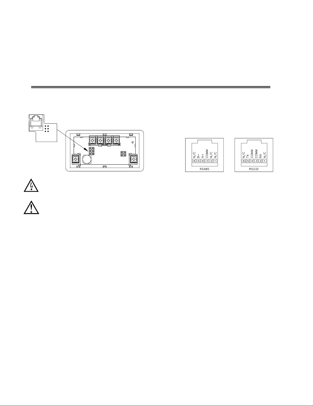
INSTALLING PLUG-IN CARDS
The cards plug into the main circuit board of the meter as shown.
WARNING: Disconnect all power to the unit before
installing Plug-in card.
CAUTION: The Plug-in cards and main circuit board contain static
sensitive components. Before handling the cards, discharge static
charges from your body by touching a grounded bare metal
object. Ideally, handle the cards at a static controlled clean
workstation. Also, only handle the cards by the edges. Dirt, oil or
other contaminants that may contact the cards can adversely
affect circuit operation.
WIRING CONNECTIONS
Connections to the serial communications cards are made through an RJ11
modular connector. Connector pin-outs for the RS485 and RS232 cards are
shown below.
SPECIFICATIONS
RS485 SERIAL COMMUNICATIONS CARD
Type: RS485 multi-point balanced interface (non-isolated)
Baud Rate: 300 to 38.4k
Data Format: 7/8 bits; odd, even, or no parity
Bus Address: 0 to 99; max 32 meters per line
Transmit Delay: Selectable, 2 msec min. or 50 msec min.
RS232 SERIAL COMMUNICATIONS CARD
Type: RS232 half duplex (non-isolated)
Baud Rate: 300 to 38.4k
Data Format: 7/8 bits; odd, even, or no parity
Comms Card
RJ11 CONNECTOR PIN OUTS
Page 4

4
DATA BIT
ABBREVIATED PRINTING
PRINT OPTIONS
PARITY BIT
METER ADDRESS
300 1200
600 2400
19200
38400
4800
9600
7-bit 8-bit
NO Odd EVEN
NO YES
NO YES
Module 5 is the programming module for the Serial Communications
Parameters. These parameters are used to match the serial settings of the
DP63000x with those of the host computer or other serial device. The Serial
Setup Parameters are only accessible when an optional RS232 or RS485 serial
communications module is installed in the meter.
MODULE 5 - S
ERIAL COMMUNICATIONS PARAMETERS (5-SEriAL)
PARAMETER MENU
BAUD RATE
Set the baud rate to match that of other serial communications equipment.
Normally, the baud rate is set to the highest value that all of the serial
communications equipment is capable of transmitting and receiving.
Select either 7- or 8-bit data word length. Set the word length to match the
other serial communications equipment on the serial link.
This parameter only appears when the Data Bit parameter is set to a 7-bit
data word length. Set the parity bit to match that of the other serial equipment
on the serial link. The meter ignores parity when receiving data and sets the
parity bit for outgoing data. If parity is set to NO, an additional stop bit is used
to force the frame size to 10 bits.
Enter the serial node address. With a single unit, an address is not needed
and a value of zero can be used (RS232 applications). Otherwise, with multiple
bussed units, a unique address number must be assigned to each meter. The
node address applies specifically to RS485 applications.
This parameter determines the formatting of data transmitted from the meter
in response to a Transmit Value command or a Block Print Request. Select
NO
for a full print transmission, consisting of the meter address, mnemonics, and
parameter data. Select YES for abbreviated print transmissions, consisting of the
parameter data only. This setting is applied to all the parameters selected in the
PRINT OPTIONS. (Note: If the meter address is 0, the address will not be sent
during a full transmission.)
This parameter selects the meter values transmitted in response to a Print
Request. A print request is also referred to as a block print because more than
one parameter can be sent to a printer or computer as a block.
Selecting
YES displays a sublist for choosing the meter parameters to appear
in the print block. All active parameters entered as YES in the sublist will be
transmitted during a block print. Parameters entered as NO will not be sent.
The “Print All” (Prnt ALL) option selects all meter values for transmitting
(YES), without having to individually select each parameter in the sublist.
Note: Inactive parameters will not be sent regardless of the print option
setting. Likewise, the Setpoint value will not be sent unless an optional setpoint
card is installed in the meter.
ª
«
9600
bAUd
ª
«
7-bit
dAtA
ª
«
Odd
PAritY
ª
«
00
Addr
ª
«
NO
Abbr
ª
«
NO
Prnt OPt
0 to 99
Indicates Program Mode Alternating Display.
Factory Settings are shown.
ª
«
C"6E
Parameter
Selection/Value
ANALOG MODELS
SP2
NO
Setpoint 2
SPt-2
SP1
NO
Setpoint 1
SPt-1
MIN
NO
Minimum
LO
MAX
NO
Maximum
HI
INP
YES
Input
INP
MNEMONIC
FACTORY
SETTING
DESCRIPTIONDISPLAY
Page 5

5
Sending Serial Commands and Data
When sending commands to the meter, a string containing at least one
command character must be constructed. A command string consists of a
command character, a value identifier, numerical data (if writing data to the
meter) followed by a command terminator character, * or $.
Command Chart
Register Identification Chart
Command String Construction
The command string must be constructed in a specific sequence. The meter
does not respond with an error message to illegal commands. The following
procedure details construction of a command string:
1. The first 2 or 3 characters consist of the Node Address Specifier (N) followed
by a 1 or 2 character node address number. The node address number of the
meter is programmable. If the node address is 0, this command and the node
address itself may be omitted. This is the only command that may be used in
conjunction with other commands.
2. After the optional address specifier, the next character is the command
character.
3. The next character is the register ID. This identifies the register that the
command affects. The P command does not require a register ID character. It
prints all the active selections chosen in the Print Options menu parameter.
4. If constructing a value change command (writing data), the numeric data is
sent next.
5. All command strings must be terminated with the string termination
characters * or $. The meter does not begin processing the command string
until this character is received. See Command Response Time section for
differences in meter response time when using the * and $ terminating
characters.
Command String Examples:
1. Node address = 17, Write 350 to the Setpoint value
String: N17VD350$
2. Node address = 5, Read Input, response time of 50 msec min
String: N5TA*
3. Node address = 0, Reset Setpoint output
String: RE*
4. Node address = 31, Request a Block Print Output, response time of 2 msec min
String: N31P$
Transmitting Data to the Meter
Numeric data sent to the meter must be limited to transmit details listed in the
Register Identification Chart. Leading zeros are ignored. Negative numbers
must have a minus sign. The meter ignores any decimal point and conforms the
number to the scaled resolution. (For example: The meter’s scaled decimal point
position is set for 0.0 and 25 is written to a register. The value of the register is
now 2.5. In this case, write a value of 250 to equal 25.0).
Note: Since the meter does not issue a reply to value change commands, follow
with a transmit value command for readback verification.
Receiving Data From The Meter
Data is transmitted from the meter in response to either a transmit command
(T), a block print request command (P) or a User Input print request. The
response from the meter is either a full field transmission or an abbreviated
transmission, depending on the selection chosen in Module 5.
Full Field Transmission
* These characters only appear in the last line of a block print.
The first two characters transmitted are the meter address. If the address
assigned is 0, two spaces are substituted. Aspace follows the meter address field.
The next three characters are the register mnemonic, as shown in the Register
Identification Chart.
The numeric data is transmitted next. The numeric field (bytes 7 to 15) is 9
characters long. When a requested display value exceeds the meter’s display
limits, decimal points are sent in place of numerical data to indicate a display
overrange.
The remaining 7 positions of this field consist of a minus sign (for negative
values), a floating decimal point (if applicable), and five positions for the
requested value. The data within bytes 9 to 15 is right-aligned with leading
spaces for any unfilled positions.
The end of the response string is terminated with a <CR> and <LF>. After the
last line of a block print, an extra <SP>, <CR> and <LF> are added to provide
separation between the print blocks.
Abbreviated Transmission
* These characters only appear in the last line of a block print.
The abbreviated response suppresses the node address and register ID,
leaving only the numeric part of the response.
Meter Response Examples:
1. Node address = 17, full field response, Input = 875
17 INP 875 <CR><LF>
2. Node address = 0, full field response, Setpoint = -250.5
SP1 -250.5<CR><LF>
3. Node address = 0, abbreviated response, Setpoint = 250, last line of block
print
250<CR><LF><SP><CR><LF>
Byte Description
1, 2 2 byte Node Address field [00-99]
3 <SP> (Space)
4-6 3 byte Register Mnemonic field
7-15
16 <CR> (carriage return)
17 <LF> (line feed)
18 <SP>* (Space)
19 <CR>* (carriage return)
20 <LF>* (line feed)
Byte Description
1-9
9 byte data field, 7 bytes for number, one byte for sign, one
byte for decimal point
10 <CR> (carriage return)
11 <LF> (line feed)
12 <SP>* (Space)
13 <CR>* (carriage return)
14 <LF>* (line feed)
9 byte data field; 7 bytes for number, one byte for sign, one byte for
decimal point
Initiates a block print output. Registers in the
print block are selected in Print Options.
Block Print Request
(read)
P
Reset a register value or setpoint output.
Must be followed by a register ID character
ResetR
Write to register of the meter. Must be
followed by a register ID character and
numeric data.
Value Change (write)V
Read a register from the meter. Must be
followed by a register ID character.
Transmit Value (read)T
Address a specific meter. Must be followed by
one or two digit node address. Not required
when node address = 0.
Node (meter)
Address Specifier
N
NotesDescriptionCommand
T, R, V,
T, R, V
T, R
T, R
T
Transmit Details (T and V)
5 digit positive/4 digit negativeSP2Setpoint 2E
SP1Setpoint 1D
5 digitMINMinimumC
5 digitMAXMaximumB
5 digitINPInputA
Applicable
Commands
MNEMONICValue DescriptionID
5 digit positive/4 digit negative
Page 6

6
Command Response Time
The meter can only receive data or transmit data at any one time (half-duplex
operation). During RS232 transmissions, the meter ignores commands while
transmitting data, but instead uses RXD as a busy signal. When sending
commands and data to the meter, a delay must be imposed before sending
another command. This allows enough time for the meter to process the
command and prepare for the next command.
At the start of the time interval t1, the computer program prints or writes the
string to the com port, thus initiating a transmission. During t1, the command
characters are under transmission and at the end of this period, the command
terminating character (* or $) is received by the meter. The time duration of t
1
is dependent on the number of characters and baud rate of the channel.
t
1
= (10 times the # of characters) / baud rate
At the start of time interval t2, the meter starts the interpretation of the
command and when complete, performs the command function. This time
interval t2varies. If no response from the meter is expected, the meter is ready
to accept another command.
If the meter is to reply with data, the time interval t2is controlled by the use
of the command terminating character. The ‘*’ terminating character results in
a response time of 50 msec. minimum. This allows sufficient time for the
release of the sending driver on the RS485 bus. Terminating the command line
with ‘$’ results in a response time (t
2
) of 2 msec. minimum. The faster response
time of this terminating character requires that sending drivers release within 2
msec. after the terminating character is received.
At the beginning of time interval t
3
, the meter responds with the first
character of the reply. As with t1, the time duration of t3is dependent on the
number of characters and baud rate of the channel. At the end of t3, the meter is
ready to receive the next command.
t3= (10 times the # of characters) / baud rate
The maximum serial throughput of the meter is limited to the sum of the
times t1, t2and t3.
Timing Diagram Figure
Communication Format
Data is transferred from the meter through a serial communication channel.
In serial communications, the voltage is switched between a high and low level
at a predetermined rate (baud rate) using ASCII encoding. The receiving device
reads the voltage levels at the same intervals and then translates the switched
levels back to a character. The voltage level conventions depend on the interface
standard. The table lists the voltage levels for each standard.
Data is transmitted one byte at a time with a variable idle period between
characters (0 to ∞). Each ASCII character is “framed” with a beginning start bit,
an optional parity bit and one or more ending stop bits. The data format and
baud rate must match that of other equipment in order for communication to
take place. The figures list the data formats employed by the meter.
Start Bit and Data Bits
Data transmission always begins with the start bit. The start bit signals the
receiving device to prepare for reception of data. One bit period later, the least
significant bit of the ASCII encoded character is transmitted, followed by the
remaining data bits. The receiving device then reads each bit position as they are
transmitted.
Parity Bit
After the data bits, the parity bit is sent. The transmitter sets the parity bit to
a zero or a one, so that the total number of ones contained in the transmission
(including the parity bit) is either even or odd. This bit is used by the receiver
to detect errors that may occur to an odd number of bits in the transmission.
However, a single parity bit cannot detect errors that may occur to an even
number of bits. Given this limitation, the parity bit is often ignored by the
receiving device. The DP63000x meter ignores the parity bit of incoming data
and sets the parity bit to odd, even or none (mark parity) for outgoing data.
Stop Bit
The last character transmitted is the stop bit. The stop bit provides a single bit
period pause to allow the receiver to prepare to re-synchronize to the start of a
new transmission (start bit of next byte). The receiver then continuously looks
for the occurrence of the start bit. If 7 data bits and no parity is selected, then 2
stop bits are sent from the meter.
Character Frame Figure
LOGIC RS232* RS485*INTERFACE STATE
1 TXD,RXD; -3 to -15 V a-b < -200 mVmark (idle)
0 TXD,RXD; +3 to +15 V a-b > +200 mVspace (active)
* Voltage levels at the Receiver
Page 7

WARRANTY/DISCLAIMER
OMEGA ENGINEERING, INC. warrants this unit to be free of defects in materials and workmanship for a
period of 25 months from date of purchase. OMEGA’s WARRANTY adds an additional one (1) month grace
period to the normal two (2) year product warranty to cover handling and shipping time. This ensures
that OMEGA’s customers receive maximum coverage on each product.
If the unit malfunctions, it must be returned to the factory for evaluation. OMEGA’s Customer Service
Department will issue an Authorized Return (AR) number immediately upon phone or written request. Upon
examination by OMEGA, if the unit is found to be defective, it will be repaired or replaced at no charge.
OMEGA’s WARRANTY does not apply to defects resulting from any action of the purchaser, including but
not limited to mishandling, improper interfacing, operation outside of design limits, improper repair, or
unauthorized modification. This WARRANTY is VOID if the unit shows evidence of having been tampered
with or shows evidence of having been damaged as a result of excessive corrosion; or current, heat,
moisture or vibration; improper specification; misapplication; misuse or other operating conditions outside
of OMEGA’s control. Components in which wear is not warranted, include but are not limited to contact
points, fuses, and triacs.
OMEGA is pleased to offer suggestions on the use of its various products. However, OMEGA
neither assumes responsibility for any omissions or errors nor assumes liability for any
damages that result from the use of its products in accordance with information provided by
OMEGA, either verbal or written. OMEGA warrants only that the parts manufactured by the
company will be as specified and free of defects. OMEGA MAKES NO OTHER WARRANTIES OR
REPRESENTATIONS OF ANY KIND WHATSOEVER, EXPRESSED OR IMPLIED, EXCEPT THAT OF
TITLE, AND ALL IMPLIED WARRANTIES INCLUDING ANY WARRANTY OF MERCHANTABILITY
AND FITNESS FOR A PARTICULAR PURPOSE ARE HEREBY DISCLAIMED. LIMITATION OF
LIABILITY: The remedies of purchaser set forth herein are exclusive, and the total liability of
OMEGA with respect to this order, whether based on contract, warranty, negligence,
indemnification, strict liability or otherwise, shall not exceed the purchase price of the
component upon which liability is based. In no event shall OMEGA be liable for consequential,
incidental or special damages.
CONDITIONS: Equipment sold by OMEGA is not intended to be used, nor shall it be used: (1) as a “Basic
Component” under 10 CFR 21 (NRC), used in or with any nuclear installation or activity; or (2) in medical
applications or used on humans. Should any Product(s) be used in or with any nuclear installation or activity,
medical application, used on humans, or misused in any way, OMEGA assumes no responsibility as set forth
in our basic WARRANTY/DISCLAIMER language, and, additionally, purchaser will indemnify OMEGA and
hold OMEGA harmless from any liability or damage whatsoever arising out of the use of the Product(s) in
such a manner.
RETURN REQUESTS/INQUIRIES
Direct all warranty and repair requests/inquiries to the OMEGA Customer Service Department. BEFORE
RETURNING ANY PRODUCT(S) TO OMEGA, PURCHASER MUST OBTAIN AN AUTHORIZED RETURN (AR)
NUMBER FROM OMEGA’S CUSTOMER SERVICE DEPARTMENT (IN ORDER TO AVOID PROCESSING
DELAYS). The assigned AR number should then be marked on the outside of the return package and on any
correspondence.
The purchaser is responsible for shipping charges, freight, insurance and proper packaging to prevent
breakage in transit.
OMEGA’s policy is to make running changes, not model changes, whenever an improvement is possible. This affords our
customers the latest in technology and engineering.
OMEGA is a registered trademark of OMEGA ENGINEERING, INC.
© Copyright 2006 OMEGA ENGINEERING, INC. All rights reserved. This document may not be copied, photocopied,
reproduced, translated, or reduced to any electronic medium or machine-readable form, in whole or in part, without the
prior written consent of OMEGA ENGINEERING, INC.
FOR WARRANTY RETURNS, please have the
following information available BEFORE
contacting OMEGA:
1. Purchase Order number under which the product
was PURCHASED,
2. Model and serial number of the product under
warranty, and
3. Repair instructions and/or specific problems
relative to the product.
FOR NON-
WARRANTY REPAIRS, consult OMEGA
for current repair charges. Have the following
information available BEFORE contacting OMEGA:
1. Purchase Order number to cover the COST of the
repair,
2. Model and serial number of the product, and
3. Repair instructions and/or specific problems
relative to the product.
Page 8

Where Do I Find Everything I Need for
Process Measurement and Control?
OMEGA…Of Course!
Shop online at omega.com
TEMPERATURE
] Thermocouple, RTD & Thermistor Probes, Connectors, Panels & Assemblies
] Wire: Thermocouple, RTD & Thermistor
] Calibrators & Ice Point References
] Recorders, Controllers & Process Monitors
] Infrared Pyrometers
PRESSURE, STRAIN AND FORCE
] Transducers & Strain Gages
] Load Cells & Pressure Gages
] Displacement Transducers
] Instrumentation & Accessories
FLOW/LEVEL
] Rotameters, Gas Mass Flowmeters & Flow Computers
] Air Velocity Indicators
] Turbine/Paddlewheel Systems
] Totalizers & Batch Controllers
pH/CONDUCTIVITY
] pH Electrodes, Testers & Accessories
] Benchtop/Laboratory Meters
] Controllers, Calibrators, Simulators & Pumps
] Industrial pH & Conductivity Equipment
DATA ACQUISITION
] Data Acquisition & Engineering Software
] Communications-Based Acquisition Systems
] Plug-in Cards for Apple, IBM & Compatibles
] Datalogging Systems
] Recorders, Printers & Plotters
HEATERS
] Heating Cable
] Cartridge & Strip Heaters
] Immersion & Band Heaters
] Flexible Heaters
] Laboratory Heaters
ENVIRONMENTAL
MONITORING AND CONTROL
] Metering & Control Instrumentation
] Refractometers
] Pumps & Tubing
] Air, Soil & Water Monitors
] Industrial Water & Wastewater Treatment
] pH, Conductivity & Dissolved Oxygen Instruments
M4532/0208
 Loading...