

Page 1

ADDENDUM
Addendum for “TX41” & "DP41Z"
TX41 Series Smart Transmitters/
DP41Z Series Split Meters
This Addendum is for the Following Manuals:
Process 11277ML-XX (M1297)
Strain 11279ML-XX (M1291)
Temperature/RTD 11275ML-XX (M1296)
Scale/Weight 11575ML-XX (M2378)
Description
The TX41 Series smart transmitters is a meter without a display. It can be
mounted on a standard DIN rail or flat surface with two (2) screws. The TX41
has an optional remote programmer/display with red or green LED’s. Only one
programmer is needed to program any of the models, but if all enunciators
and/or push buttons are required for remote display mounting, you must order
the TX41-RM (red display) or TX41-RM-GR (green display).
The DP41Z Series is the same as TX41 except it includes the remote display
with standart 3 foot cable. If a longer distance is required, you may use up to
200 feet of 26 conductor IDC flat ribbon or shielded round cable available from
many suppliers.
Unpacking and Safety Considerations
Refer to appropriate section of the operators manual.
Mounting
Mounting Meter to DIN Rail:
Unit mounts to a standard 35mm DIN rail by placing the upper catch over the
top of the DIN rail and then rotating the case downward until the bottom latch
snaps on to the bottom of the rail; locking the meter in place (Figure 3).
To remove from rail, press down in the center of the plastic movable rib at the
top of the meter and rotate bottom outward then lift up (Figure 3).
Page 2

Mounting Meter to Surface:
Use the meter template (Figure 5) to mark location of mounting screws on a flat
surface. Take care to leave room at the display connector door end of the meter
to slide meter in or out of sleeve once mounted. The meter can be moved from
the sleeve by unscrewing 2 thumb nuts (easiest if clear plastic cover removed
and connectors are unplugged).
Mounting Programmer/Display Through Panel:
Using the panel diagram (Figure 4), cut a hole in the panel. (Panel thickness
should be between 0.03” to 0.25” thick). Remove screws at back of remote
display to remove back cover. Slide tree end of ribbon cable and back cover
through panel cutout from front side of panel. Align back cover to remote display
and reinstall screws. Take care to seat gasket on front panel property (Figure 1).
Mounting Programmer/Display on Bail:
Use the programmer/display template (Figure 6) to mark the location of
mounting screws on a flat surface. Be sure to leave enough room around the
bail (as noted on the template drawing) to allow for removal and rotation of the
display. The display can be rotated to 12 positions for the best viewing angle. To
remove the display from the bail, spread mounting ears.
Specifications
Refer to appropriate section of the operators manual.
Page 3
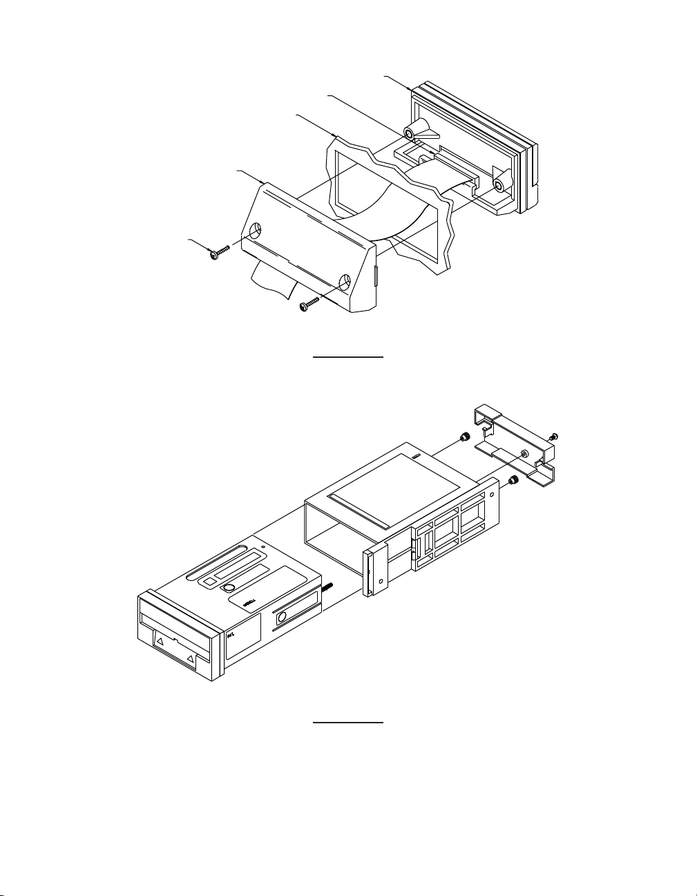
SCREWS
B
ACK COVER
PANEL MOUNTING
C
ONNECTOR
GASKET
FIGURE 1
FIGURE 2
Page 4

FIGURE 3
PROGRAMMER/DISPLAY PANEL CUT-OUT
PROGRAMMER/DISPLAY FRONT & SIDE VIEW
SHOWN WITH BAIL MOUNT
METER-SIDE VIEW METER-TOP VIEW
FIGURE 4
Page 5
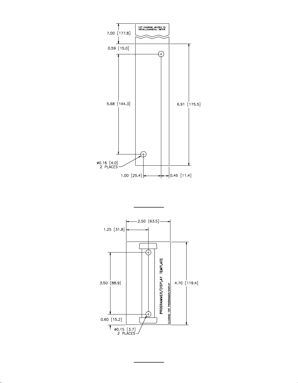
PROGRAMMER/DISPLAY TEMPLATE
METER TEMPLATE
P
FIGURE 5
FIGURE 6
Page 6
It is the policy of OMEGA to comply with all worldwide safety and EMC/EMI regulations that apply. OMEGAis constantly pursuing certification of its products to the European New
Approach Directives. OMEGAwill add the CE mark to every appropriate device upon certification.
The information contained in this document is believed to be correct, but OMEGA Engineering, Inc. accepts no liability for any errors it contains, and reserves the right to alter
specifications without notice.
WARNING: These products are notdesigned for use in, and should not be used for, patient-connected applications.
This device is marked with the international caution symbol. It is important to read the Setup Guide before installing or commissioning this device as the guide contains important
information relating to safety and EMC.
This device is marked with the international caution symbol. It is important to read the Setup Guide before installing or commissioning this device as the guide contains
important information relating to safety and EMC.
Page 7

WARRANTY/ DISCLAIMER
OMEGA ENGINEERING, INC. warrants this unit to be free of defects in materials and workmanship for a period of
one (1) year from the date of purchase. In addition to OMEGA’s standard warranty period, OMEGA Engineering will
extend the warranty period for four (4) additional years if the warranty card enclosed with each instrument is
returned to OMEGA.
If the unit malfunctions, it must be returned to the factory for evaluation. OMEGA’s Customer Service Department
will issue an Authorized Return (AR) number immediately upon phone or written request. Upon examination by
OMEGA, if the unit is found to be defective, it will be repaired or replaced at no charge. OMEGA’s WARRANTY does
not apply to defects resulting from any action of the purchaser, including but not limited to mishandling, improper
interfacing, operation outside of design limits, improper repair, or unauthorized modification. This WARRANTY is
VOID if the unit shows evidence of having been tampered with or shows evidence of having been damaged as a
result of excessive corrosion; or current, heat, moisture or vibration; improper specification; misapplication; misuse
or other operating conditions outside of OMEGA’s control. Components which wear are not warranted, including but
not limited to contact points, fuses, and triacs.
OMEGA is pleased to offer suggestions on the use of its various products. However, OMEGA neither
assumes responsibility for any omissions or errors nor assumes liability for any damages that result from
the use of its products in accordance with information provided by OMEGA, either verbal or written.
OMEGA warrants only that the parts manufactured by it will be as specified and free of defects. OMEGA
MAKES NO OTHER WARRANTIES OR REPRESENTATIONS OF ANY KIND WHATSOEVER, EXPRESS OR
IMPLIED, EXCEPT THAT OF TITLE, AND ALL IMPLIED WARRANTIES INCLUDING ANY WARRANTY OF
MERCHANTABILITY AND FITNESS FOR A PARTICULAR PURPOSE ARE HEREBY DISCLAIMED.
LIMITATION OF LIABILITY: The remedies of purchaser set forth herein are exclusive, and the total liability
of OMEGA with respect to this order, whether based on contract, warranty, negligence, indemnification,
strict liability or otherwise, shall not exceed the purchase price of the component upon which liability is
based. In no event shall OMEGA be liable for consequential, incidental or special damages.
CONDITIONS: Equipment sold by OMEGA is not intended to be used, nor shall it be used: (1) as a “Basic
Component” under 10 CFR 21 (NRC), used in or with any nuclear installation or activity; or (2) in medical
applications or used on humans. Should any Product(s) be used in or with any nuclear installation or activity,
medical application, used on humans, or misused in any way, OMEGA assumes no responsibility as set forth
in our basic WARRANTY/ DISCLAIMER language, and, additionally, purchaser will indemnify OMEGA and hold
OMEGA harmless from any liability or damage whatsoever arising out of the use of the Product(s) in such a
manner.
RETURN REQUESTS/INQUIRIES
Direct all warranty and repair requests/inquiries to the OMEGA Customer Service Department. BEFORE
RETURNING ANY PRODUCT(S) TO OMEGA, PURCHASER MUST OBTAIN AN AUTHORIZED RETURN
(A R ) N U MBER FROM OMEG A’ S C U STO M E R S E RVI C E D E PART M ENT (IN ORDE R T O AVO I D
PROCESSING DELAYS). The assigned AR number should then be marked on the outside of the return
package and on any correspondence.
The purchaser is responsible for shipping charges, freight, insurance and proper packaging to prevent
breakage in transit.
FOR WARRANTY RETURNS, please have the
following information available BEFORE
contacting OMEGA:
1. Purchase Order number under which the product
was PURCHASED,
2. Model and serial number of the product under
warranty, and
3. Repair instructions and/or specific problems
relative to the product.
OMEGA’s policy is to make running changes, not model changes, whenever an improvement is possible. This affords our
customers the latest in technology and engineering.
© Copyright 2008 OMEGA ENGINEERING, INC. All rights reserved. This document may not be copied, photocopied, reproduced,
translated, or reduced to any electronic medium or machine-readable form, in whole or in part, without the prior written consent of
OMEGA ENGINEERING, INC.
TRADEMARK NOTICE:
PATENT NOTICE: This product is covered by one or more of the following patents: U.S. Pat. No. Des. 336,895; 5,274,577/ CANADA
2052599; 2052600 / ITALY 1249456; 1250938 / FRANCE BREVET No. 91 12756 / SPAIN 2039150; 2048066 / UK PATENT No. GB2
249 837; GB2 248 954 / GERMANY DE 41 34398 C2. Other US and International Patents pending or
applied for.
®
, omega.com
®
, are Trademarks of OMEGA ENGINEERING, INC.
FOR NON-WARRANTY REPAIRS,
consult OMEGA for
current repair charges. Have the following information
available BEFORE contacting OMEGA:
1. Purchase Order number to cover the COST
of the repair,
2. Model and serial number of product, and
3. Repair instructions and/or specific problems
relative to the product.
Page 8

Where Do I Find Everything I Need for
Process Measurement and Control?
OMEGA…Of Course!
Shop on line at omega.com
TEMPERATURE
Ther
PRESSURE, STRAIN AND FORCE
FLOW/LEVEL
pH/CONDUCTIVITY
mocouple, RTD & Thermistor Probes, Connectors, Panels & Assemblies
Wire: Thermocouple, RTD & Thermistor
Calibrators & Ice Point References
Recorders, Controllers & Process Monitors
Infrared Pyrometers
Transducers & Strain Gauges
Load Cells & Pressure Gauges
Displacement Transducers
Instrumentation & Accessories
Rotameters, Gas Mass Flowmeters & Flow Computers
Air Velocity Indicators
Turbine/Paddlewheel Systems
Totalizers & Batch Controllers
pH Electrodes, Testers & Accessories
Benchtop/Laboratory Meters
Controllers, Calibrators, Simulators & Pumps
Industrial pH & Conductivity Equipment
DATA ACQUISITION
Data Acquisition & Engineering Software
Communications-Based Acquisition Systems
Plug-in Cards for Apple, IBM & Compatibles
Datalogging Systems
Recorders, Printers & Plotters
HEATERS
Heating Cable
Cartridge & Strip Heaters
Immersion & Band Heaters
Flexible Heaters
Laboratory Heaters
ENVIRONMENTAL
MONITORING AND CONTROL
Metering & Control Instrumentation
Refractometers
Pumps & Tubing
Air, Soil & Water Monitors
Industrial Water & Wastewater Treatment
pH, Conductivity & Dissolved Oxygen Instruments
M1296A/1008 11472ML-99C
 Loading...