

Page 1
omega.com
e-mail: info@omega.com
For latest product manuals:
omegamanual.info
™
®
User’s Guide
DP41-E
High Performance
Process Indicator
MADE IN
USA
Page 2

It is the policy of OMEGA to comply with all worldwide safety and EMC/EMI regulations that apply.
OMEGA is constantly pursuing certification of its products to the European New Approach Directives. OMEGA will add
the CE mark to every appropriate device upon certification.
The information contained in this document is believed to be correct but OMEGA Engineering, Inc. accepts no liability for any errors it contains,
and reserves the right to alter specifications without notice.
WARNING: These products are not designed for use in, and should not be used for, patient connected applications.
This device is marked with the international hazard symbol. It is important to read the Setup Guide before installing or commissioning
this device as it contains important information relating to safety and EMC.
®
®
OMEGAnet® On-Line Service
www.omega.com
Internet e-mail
info@omega.com
Servicing North America:
USA: One Omega Drive, P.O. Box 4047
ISO 9001 Certified Stamford CT 06907-0047
TEL: (203) 359-1660 FAX: (203) 359-7700
e-mail: info@omega.com
Canada: 976 Bergar
Laval (Quebec) H7L 5A1
TEL: (514) 856-6928 FAX: (514) 856-6886
e-mail: info@omega.ca
For immediate technical or application assistance:
USA and Canada: Sales Service: 1-800-826-6342 / 1-800-TC-OMEGA
Customer Service: 1-800-622-2378 / 1-800-622-BEST
Engineering Service: 1-800-872-9436 / 1-800-USA-WHEN
Mexico and TEL: (001) 203-359-7803 FAX: (001) 203-359-7807
Latin America: e-mail: espanol@omega.com
®
®
®
Servicing Europe:
Benelux: TEL: +31 20 3472121 FAX: +31 20 6434643
Toll Free in Benelux: 0800 0993344
e-mail: sales@omegaeng.nl
Czech Republic: Frystatska 184, 733 01 Karviná
TEL: +420 59 6311899 FAX: +420 59 631111 4
e-mail: info@omegashop.cz
France: TEL: +33 1 61 37 29 00 FAX: +33 1 30 57 54 27
Toll Free in France: 0800 466 342
e-mail: sales@omega.fr
Germany/Austria: Daimlerstrasse 26, D-75392 Deckenpfronn, Germany
TEL: +49 7056 9398-0 FAX: +49 7056 9398-29
Toll Free in Germany: 0800 639 7678
e-mail: info@omega.de
United Kingdom: One Omega Drive
ISO 9001 Certified River Bend Technology Centre
Northbank, Irlam Manchester M44 5BD United Kingdom
TEL: +44 161 777 6611 FAX: +44 161 777 6622
Toll Free in England: 0800 488 488
e-mail: sales@omega.co.uk
Page 3

SECTION 1 INTRODUCTION
1.1 Description................................................................................1
1.2 Features....................................................................................1
1.3 Available Models.......................................................................2
SECTION 2 UNPACKING ............................................................................4
SECTION 3 SAFETY CONSIDERATIONS
3.1 Safety Considerations...............................................................6
SECTION 4 PARTS OF THE METER
4.1 Front of the Meter .....................................................................7
4.2 Rear of the Meter....................................................................10
SECTION 5 SETUP
5.1 Conditions Requiring Disassembly .........................................13
5.2 Assembly/Disassembly Opening ............................................13
5.2.1 Safety Precaution/Product ID Label........................................16
5.2.2 Main Board Power Jumpers....................................................17
5.2.3 Printed Circuit Board(s) Installation ........................................18
5.2.4 How to Access Jumpers..........................................................19
5.2.5 Panel-Mount Assembly...........................................................23
SECTION 6 JUMPER POSITIONS
6.1 Introduction .............................................................................26
6.2 S1 Jumper Positions for Readrate and
Unipolar or Bipolar Input(s).....................................................26
6.3 S2 Jumper Positions for Input Range .....................................26
6.4 Jumper setting(s) for Sensor Excitation..................................28
6.4.1 Jumper setting(s) for Sensor Excitation ac-powered unit .......28
6.4.2 Jumper setting(s) for Sensor Excitation dc-powered unit .......30
SECTION 7 SIGNAL AND POWER INPUT CONNECTIONS
7.1 Introduction .............................................................................31
7.2 Signal Input Connections........................................................31
7.3 Connecting Main Power..........................................................33
SECTION 8 SCALING TO DISPLAY IN ENGINEERING UNITS
8.1 Introduction .............................................................................35
8.2 Setup Meter Input Type and Range ........................................35
8.3 Scaling your meter using 2-coordinate input scale and Offset
(IN.SC.OF) with sensor connected to your meter...................37
8.3.1 Setting Input Configuration (“IN CNF”)....................................38
8.3.2 Scaling your meter with your sensor connected .....................39
8.3.3 To select Decimal Point Position (DEC PT) ............................42
i
Table of Contents
Page 4

SECTION 8 SCALING TO DISPLAY IN ENGINEERING UNITS
8.3.4 Entering Zero Offset numbers.................................................43
8.4 Scaling your meter without connecting a sensor
using calculated values...........................................................45
8.4.1 Preparing your meter for scaling with Input Scale and Offset.......45
8.4.2 Scaling your meter..................................................................48
8.4.3 To select Decimal Point Position.............................................52
8.4.4 Entering Zero Offset Numbers................................................54
SECTION 9 METER FUNCTION MENUS
9.1 Individual Lockout Information ................................................57
9.2 Meter Function Menus ............................................................63
9.2.1 Input........................................................................................63
9.2.2 RDG.CNF (Reading Configuration) ........................................63
9.2.3 RDG SC (Reading Scale) and RDG OF (Reading Offset)......65
9.2.4 IN CNF (Input Configuration) ..................................................67
9.2.5 IN.SC.OF (Input Scale and Offset) .........................................68
9.2.6 DEC PT (Decimal Point) .........................................................70
9.2.7 CNT BY (Count By).................................................................71
9.2.8 FIL.CNF (Filter Configuration).................................................72
9.2.9 FIL TI (Filter Time Constant) ...................................................73
9.2.10 SP CNF (Setpoints 1 & 2 Configuration).................................74
9.2.11 AL CNF (Alarm Configuration)................................................75
9.2.12 AL FNC (Alarm Function)........................................................77
9.2.13 AL RDG (Alarm Readings)......................................................78
9.2.14 SP DB (Setpoint Deadband)...................................................79
9.2.15 AL DB (Alarm Deadband) .......................................................79
9.2.16 OUT.CNF (Output Configuration)............................................80
9.2.17 OT.SC.OF (Output Scale and Offset)......................................81
9.2.18 BAUD (Baud Rate)..................................................................82
9.2.19 SERCNF (Serial Communication Configuration) ....................83
9.2.20 ADDRESS (Multipoint Communications Device Address)......84
9.2.21 DAT FT (Data Format) ............................................................84
9.2.22 BUS FT (Bus Format) .............................................................86
9.2.23 SERCNT (Serial Count)..........................................................87
9.2.24 Analog Output Calibration Numbers .......................................88
Table of Contents
ii
Page 5

SECTION 10 SETPOINTS/ALARMS
10.1 Features overview...................................................................89
10.2 Unlocking the Features...........................................................91
10.3 Selecting “SP CNF” Setpoint Configuration Features.............91
10.4 Deviation Function for Alarms.................................................92
10.5 Selecting “AL CNF” Alarm Configuration Features .................93
10.6 Selecting “AL FNC” Alarm Configuration Features .................95
10.7 “AL RDG”: Alarm Readings-Select Delay in Alarm Action.......96
10.8 “SP DB”: Select “SP 1”and “SP 2” Deadband (Hysteresis).....96
10.9 “AL DB”: Select Alarm 1 (“SP 3”)
and Alarm 2 (“SP 4”) Deadband ( Hysteresis) ........................96
10.10 “OUT.CNF”: Control Flashing of the Display ...........................97
10.11 Entering Setpoint Levels (in Run Mode) .................................97
SECTION 11 PEAK AND VALLEY READINGS ..........................................98
SECTION 12 ANALOG OUTPUT OPTION
12.1 Features Overview..................................................................99
12.2 Unlocking ..............................................................................100
12.3 “OUT.CNF”: Configuring the Output......................................100
12.4 “OT.SC.OF”: Setting Output Scale and Offset ......................100
12.5 Board Installation; Entering the trim Data .............................101
12.6 Filter Configuration “FIL.CNF” Value to be transmitted ........103
12.7 Wiring/Connections...............................................................103
SECTION 13 BCD OPTION
13.1 Features Overview................................................................104
13.2 BCD Card Jumper Table .......................................................106
13.3 Interconnect Board................................................................106
13.4 50-Line Cable Compatibility..................................................107
13.5 Selecting the source of BCD Data: “OUT.CNF” ....................107
13.6 Hold Control..........................................................................107
13.7 Data Ready Timing Pulses....................................................107
13.8 Bringing out the BCD Overflow line ......................................107
13.9 3 Digit at a time Multiplex......................................................107
13.10 6 Digit at a time Card Address..............................................108
13.11 Select Data Polarity: Jumper S8...........................................109
13.12 Decimal Point Address Code................................................109
13.13 Applying Non-Isolated/Isolated Power..................................109
13.14 Driving a Printer ....................................................................109
SECTION 14 RELAY OPTIONS
14.1 Features Overview ................................................................110
14.2 Wiring/Connections ...............................................................112
iii
Table of Contents
Page 6

SECTION 15 RS-232 OR RS-485 OPTION BOARD
15.1 Features Overview ................................................................113
15.2 Front-Panel Pushbutton Configuration..................................115
SECTION 16 EXTERNAL CONTROL LINES
16.1 TARE (PIN 1) ........................................................................116
16.2 PEAK (PIN 2) ........................................................................116
16.3 VALLEY (PIN 3).....................................................................117
16.4 SWLIN2 (PIN 4) ....................................................................117
16.5 PEAK & VALLEY or EXTERNAL RESET (PIN 5)..................117
16.6 PUSH TO CAL (PIN 6) ..........................................................117
16.7 Digital Return (PIN 7) ............................................................117
16.8 +5 V (PIN 8) ..........................................................................117
16.9 Display Hold (PIN 9)..............................................................117
16.10 LOCKOUT EEPROM (and ‘MENU’ BUTTON) (PIN 10)........117
16.11 Print Command and/or Reset of Alarms (PIN 11) .................117
16.12 Nonstandard RX (PIN 12) and Nonstandard TX (PIN 13).....118
16.13 PUSH TO CAL (PIN 14) ........................................................118
16.14 +V EXT (PIN 15) ...................................................................118
16.15 SP1 (PIN 16) .........................................................................118
16.16 SP2 (PIN 17) .........................................................................118
16.17 AL1 (PIN 18) .........................................................................118
16.18 AL2 (PIN 19) .........................................................................118
16.19 RTN EXT (PIN 20).................................................................118
SECTION 17 DISPLAY MESSAGES AND TROUBLESHOOTING GUIDE
17.1 Error Mode Message.............................................................119
17.1.1 Flashing “999999” (Numerical Overflow) ..............................119
17.1.2 Flashing “ERR O1” (Offset Overflow)....................................119
17.1.3 Flashing “ERR O2” (Setpoint Overflow) ................................119
17.1.4 “NOSTOR” & “STORED
(Programming Entries In EEPROM) .....................................119
17.1.5 Flashing “+OVLD” (Positive Input Overload).........................119
17.1.6 Flashing “+OPEN” (Open Sensor Indication)........................119
17.1.7 Flashing “-OPEN” (Open Sensor Indication).........................120
17.1.8 Flashing “I OVSC” (Input Overscale) ....................................120
17.1.9 Flashing “R OVSC” (Reading Overscale) .............................120
17.1.10 Flashing “CB OVF” (Count By Overflow) ..............................120
17.1.11 Flashing “UOM.OVF” (Unit Of Measure Overflow) ...............120
17.2 Troubleshooting Guide..........................................................120
SECTION 18 SPECIFICATIONS
18.1 Current Input.........................................................................123
18.2 Voltage Input.........................................................................123
18.3 Potentiometer Input...............................................................123
18.4 General .................................................................................123
Table of Contents
iv
Page 7

SECTION 19 FACTORY PRESET VALUES ..............................................128
SECTION 20 RECORD YOUR SETUP VALUES .......................................131
v
Table of Contents
Page 8

Figure 4-1 Front Detail ............................................................................7
Figure 4-2A AC Power - Connector Label for Rear Connectors .............10
Figure 4-2B DC Power - Connector Label for Rear Connectors..............11
Figure 4-3 Rear View with the optional 4-relay output board
and a serial communications board installed.......................12
Figure 4-4 Rear View with the optional BCD output board
and a serial communications output board installed............12
Figure 5-1 Meter Exploded View...........................................................14
Figure 5-2 Board Assembly Removing/Installing Detail ........................15
Figure 5-3 Transformer Jumpers ..........................................................17
Figure 5-4 Optional Printed Circuit Board Locations.............................18
Figure 5-5 Signal Input Board ...............................................................19
Figure 5-6 ac-Powered Main Board ......................................................20
Figure 5-7 dc-Powered Main Board ......................................................20
Figure 5-8 Relay Option Board .............................................................21
Figure 5-9 4-Relay Option Board ..........................................................21
Figure 5-10 Analog Output Option Board ...............................................22
Figure 5-11 RS-232 Option Board ..........................................................22
Figure 5-12 RS-485 Option Board ..........................................................22
Figure 5-13 BCD Option Board ...............................................................23
Figure 5-14 Panel Mounting Assembly ...................................................24
Figure 6-1 S1 and S2 Jumper Locations on Signal Input Board...........26
Figure 6-2 ac Main Board Jumper Positions S3 and S4 .......................29
Figure 6-3 dc Main Board Jumper Positions S3 and S4 .......................30
Figure 7-1 Current Input Without Sensor Excitation .............................31
Figure 7-2 Current Input With Sensor Excitation ..................................31
Figure 7-3 Voltage Input Without Sensor Excitation .............................32
Figure 7-4 3-Wire Voltage Input With Sensor Excitation.......................32
Figure 7-5 4-Wire Voltage Input With Sensor Excitation.......................32
Figure 7-6 Potentiometer Connections with Internal Power Supply
and Ratio Measurement. .....................................................33
Figure 7-7 Potentiometer Connections With External Power Supply
and Ratio Measurement (Remove jumper S2-T).................33
Figure 7-8 AC Connector Wiring at P1 .................................................34
Figures
vi
Page 9

Figure 7-9 DC Connector Wiring at P1 .................................................34
Figure 8-1 Factory Calculated Scale Factors........................................48
Figure 10-1 Setpoints 1 & 2 Action .........................................................90
Figure 10-2 Setpoints 3 & 4 Action .........................................................90
Figure 10-3 Process Deviation................................................................92
Figure 10-4 High Deviation for both Active Above and Active Below ......92
Figure 10-5 Low Deviation for both Active Above and Active Below.......93
Figure 10-6 Band Deviation for both Active Above and Active Below .....93
Figure 10-7 AL CNF Hysteresis ..............................................................94
Figure 12-1 Analog Option Board and Connection Diagram at P5. ......101
Figure 12-2 Isolated Analog Output Board Wiring Connections. ..........103
Figure 13-1 BCD 40-Pin Cable Connector (P8) ....................................104
Figure 13-2 BCD Option Board .............................................................105
Figure 13-3 Address Programming Chart for 4 -line Address ...............108
Figure 14-1 Dual Relay .........................................................................110
Figure 14-2 4 Relay Board Jumpers and Plugs.....................................111
Figure 14-3 Dual Relay Output Board Wiring Connections...................112
Figure 14-4 4 Relay Output Board Wiring Connections ........................112
Figure 15-1 RS-232/RS-485 Option Board and Pin Designations ........114
Figure 15-2a Older RS-232 Option Board and Pin Designations ............114
Figure 15-2b Older RS-485 Option Board and Pin Designations ............114
Figure 16-1 Connector Label Detail ......................................................116
Figure 16-2 Connection of External Power for Setpoint Transistors .....118
Figure 18-1 Meter Housing and Panel Cutout. .....................................132
Table 4-1 Rear Connector Descriptions ..............................................12
Table 14-1 Dual Relay Board Jumpers................................................110
Table 14-2 4 Relay Board Jumpers......................................................111
Table 14-3 Pin assignments for the P6, P7 and P18 plugs..................112
vii
Figures
Page 10
Information that is especially important to note is identified by these labels:
• NOTE
• WARNING
• CAUTION
• IMPORTANT
NOTE: provides you with information that is important to successfully setup
and use the Programmable Digital Meter.
CAUTION or WARNING: tells you about the risk of electric shock.
CAUTION, WARNING or IMPORTANT: tells you of circumstances or
practices that can effect the meter's functionality and must refer to
accompanying documents.
Notes, Warnings, and Cautions
viii
Note
☞
Page 11

1.1 DESCRIPTION
This Process meter is part of a complete line of process indicators/
controllers, offering exceptional performance.
The process meter is front panel programmable to accept 0-20 and 4-20
mAdc current inputs, unipolar and bipolar DC voltage inputs and
potentiometer inputs. The meter will accept inputs from most of the process
sensors in use today such as transmitters, pressure transducers, and potentiometers.
Configuring the meter is accomplished through the 5 front panel buttons. If
the RS-232 or RS-485 communication option is installed, the user may
remotely set the display parameters.
Options for the meter include analog and BCD outputs, relay outputs, and
RS-232 or RS-485 communications.
1.2 FEATURES
The following is a list of features of the meter.
• 6-digit LED display in red or green
• 0.005% accuracy of reading
• 12 DC input ranges: 0-100 mV, 0-1 V, 0-5 V, 1-5 V, 0-10 V, 0-100 V,
±50 mV, ±500 mV, ±5 V, ±50 V, 0-20 mA, or 4-20 mA
• 10 or 24 V dc sensor excitation
• Peak & Valley detection and memory
• External Tare
• Up to 13 readings per second
• 4 isolated open collector outputs(standard) and optional isolated relay or
isolated BCD and isolated analog outputs
• Optional isolated RS-232 or RS-485 communications
• NEMA 4 Front Panel/IP65
• Non-volatile memory without battery back-up
• 115 Vac, 50/60 Hz, 230 Vac, 50/60 Hz power supply
• Optional 10-32 Vdc power supply
1
Introduction
1
Page 12
1.3 AVAILABLE MODELS
The following models and options are available. Optional boards are either
installed at the time of purchase, or available as separate items and installed
by the user after purchase.
MAIN ASSEMBLIES
MODEL
NUMBER DESCRIPTION
DP41E Red LEDs, 115 V ac, 50/60Hz
DP41E-230 Red LEDs, 230 V ac, 50/60Hz
DP41E-GN Green LED’s, 115 V ac, 50/60 Hz
DP41E-230-GN Green LED’s, 230 V ac, 50/60Hz
DP41E-DC Red LEDs, 10-32 V dc
DP41E-DC-GN Green LED’s, 10-32 V dc
NOTE: The following options are available installed at the time of purchase
or as separate items installed by the user after purchase:
Analog Output Board, BCD Output Board, Relay Output Board, RS-232
Communications Board, and RS-485 Communications Board.
CONTROL/BCD OUTPUT OPTIONS
MODEL
NUMBER DESCRIPTION
- Standard four open-collector outputs are standard
DP40-B Isolated BCD Output Board
DP40-R Dual 7A Form-C Relays
DP40-R4 Dual 7A & Dual 1A Form-C Relays
NOTE: Choose only one Control/BCD output option per meter. A 40-pin
mating connector is included with the BCD option.
ANALOG OUTPUT
MODEL
NUMBER DESCRIPTION
- None
DP40-A Isolated configurable analog (4-20 mA, 0-1, 0-5, 1-5,
0-10 V dc, 0-20 mA) output
1
Introduction
2
Note
Note
☞
☞
Page 13

SERIAL COMMUNICATIONS OPTION
MODEL
NUMBER DESCRIPTION
DP40-S2 * Isolated RS-232 Communications
DP40-S4 ** Isolated RS-485 Communications
NOTES: Choose only one option per meter. Both computer communications
comes with 6 ft. communications cable with phone plug termination.
Free configuration software is available from www.omega.com or on the
CD-ROM enclosed with your shipment.
* Recommend purchase of DP40-9SC2 or DP40-25SC2
(see OPTIONS below)
** Recommend purchase of DP40-9SC4 or DP40-25SC4
(see OPTIONS below)
OPTIONS
MODEL
NUMBER DESCRIPTION
DP40-9SC2 9-pin Serial Connector for RS-232
DP40-9SC4 9-pin Serial Connector for RS-485
DP40-25SC2 25-pin Serial Connector for RS-232
DP40-25SC4 25-pin Serial Connector for RS-485
SPC4 1/8 DIN NEMA 4 heavy duty cover with thumb screws
SPC18 1/8 DIN NEMA 4 Splash Proof lens cover with spring clip
3
Introduction
1
Note
☞
Page 14
Unpack all items and make sure that every item on the packing list is
present. The items you should receive are listed below. If something is
missing, use the phone number for the Customer Service Department
nearest you.
Also, inspect the shipping container and enclosed equipment for any signs of
damage. Take particular note of any evidence of rough handling in transit.
Immediately report any damage to the shipping agent.
NOTE: The shipping agent will not honor any claims unless all shipping
material is saved for their examination. After examining and removing
contents, save all packing material and containers in the event that
reshipment is required.
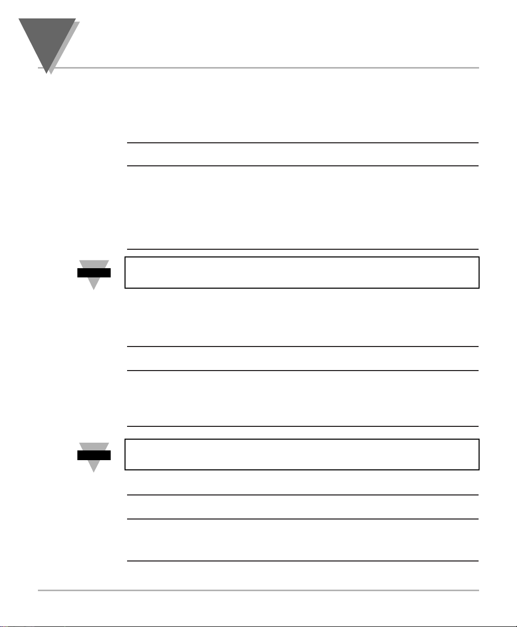
When you ordered your process meter, you will receive the following items in
the shipping box:
QTY
DESCRIPTION ILLUSTRATION
1 Basic Meter in a Mounting
Sleeve with Gasket
1 Front-Panel Button Cover
AC Power Connector
(orange - P1)
2 Input Connectors
(gray - P3 and P9)
2
Unpacking
4
1
2
3
P1
N
L
1
2
3
Note
☞
Page 15
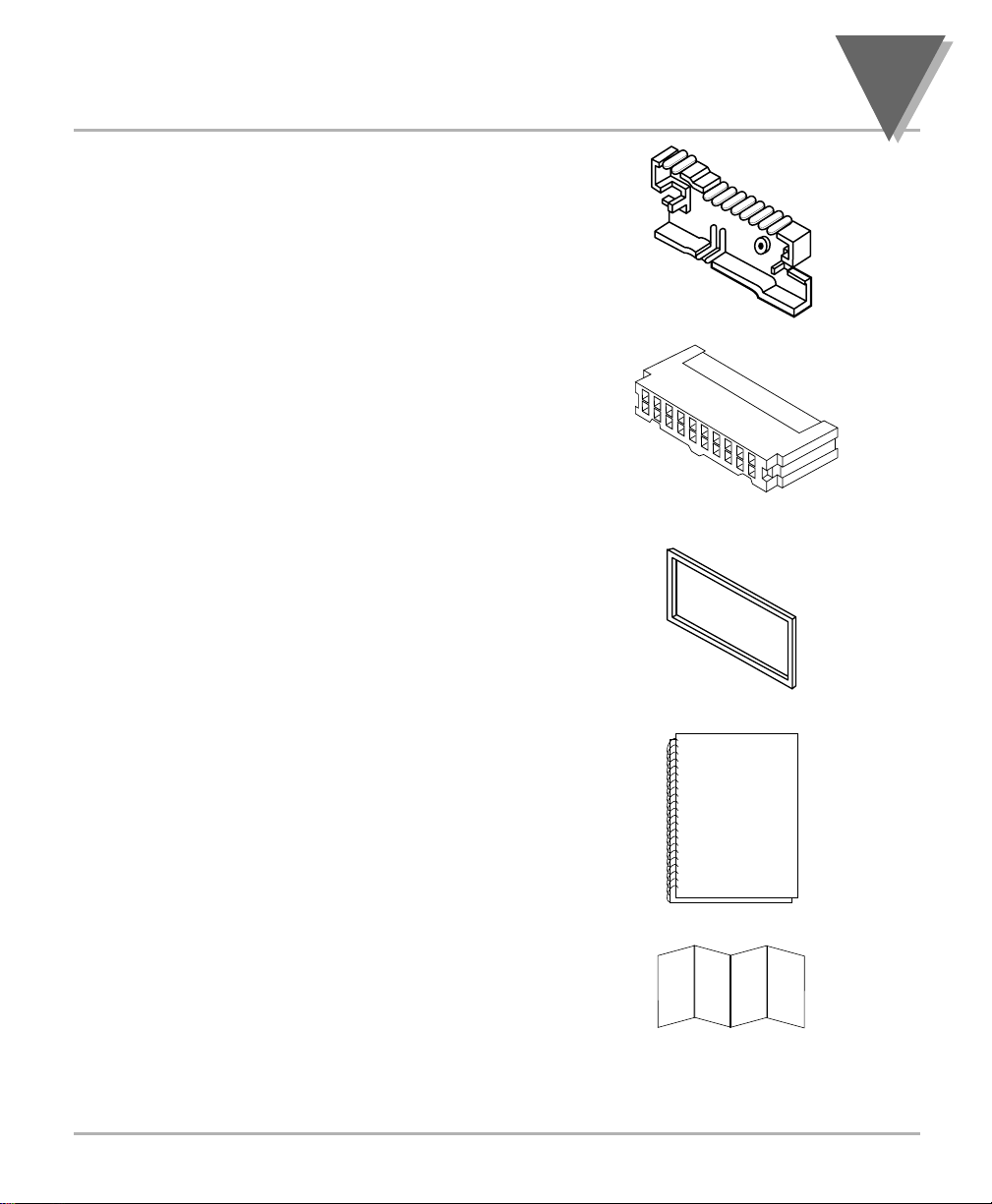
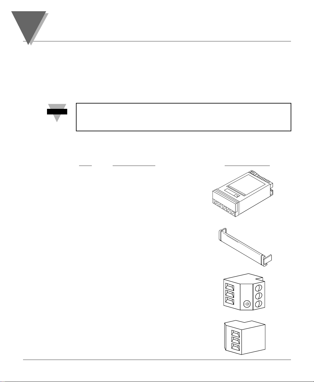
1 Rear Protective
Cover with Screw
1 20-Socket Ribbon
Connector
(P2 Connector)
2 Panel-Mounting
Gaskets (1 Spare)
1 Process Owner’s Guide
1 Quick Start Manual
Other items may also be in the box depending on the options ordered. Refer
to specific options described previously.
5
Unpacking
2
Page 16
3.1 SAFETY CONSIDERATIONS
This device is marked with the international caution symbol. It is important to read
this manual before installing or commissioning this device as it contains important
information relating to Safety and EMC
(Electromagnetic Compatibility).
Unpacking & Inspection
Unpack the instrument and inspect for obvious shipping damage. Do not attempt to
operate the unit if damage is found.
This instrument is a panel mount device protected in accordance with Class I of EN
61010 (115/230 AC power connections), Class III for the DC power option (10-32Vdc).
Installation of this instrument should be done by Qualified personnel. In order to ensure
safe operation, the following instructions should be followed.
This instrument has no power-on switch. An external switch or circuit-breaker shall be included
in the building installation as a disconnecting device. It shall be marked to indicate this function,
and it shall be in close proximity to the equipment within easy reach of the operator. The switch or
circuit-breaker shall not interrupt the Protective Conductor (Earth wire), and it shall meet the
relevant requirements of IEC 947–1 and IEC 947-3 (International Electrotechnical Commission).
The switch shall not be incorporated in the mains supply cord.
Furthermore, to provide protection against excessive energy being drawn from the
mains supply in case of a fault in the equipment, an overcurrent protection device shall
be installed.
• The Protective Conductor must be connected for safety reasons. Check that the
power cable has the proper Earth wire, and it is properly connected. It is not safe
to operate this unit without the Protective Conductor Terminal connected.
Conductor Terminal connected.
• Do not exceed voltage rating on the label located on the top of the instrument
housing.
• Always disconnect power before changing signal and power connections.
• Do not use this instrument on a work bench without its case for safety reasons.
• Do not operate this instrument in flammable or explosive atmospheres.
• Do not expose this instrument to rain or moisture.
• Unit mounting should allow for adequate ventilation to ensure instrument does
not exceed operating temperature rating.
• Use electrical wires with adequate size to handle mechanical strain and power
requirements. Install without exposing bare wire outside the connector to
minimize electrical shock hazards.
EMC Considerations
• Whenever EMC is an issue, always use shielded cables.
• Never run signal and power wires in the same conduit.
• Use signal wire connections with twisted-pair cables.
• Install Ferrite Bead(s) on signal wires close to the instrument if EMC problems
persist.
Failure to follow all instructions and warnings may result in injury!
3
Safety Considerations
6
Note
Note
☞
☞
Page 17

4.1 FRONT OF THE METER
The following is a brief description of each part of the front of the meter.
Figure 4-1. Front Detail
ITEM DESCRIPTION
1 –.8.8.8.8.8. or 8.8.8.8.8.8.
6-digit, 14 segment, alphanumeric 0.54” high LED display with
programmable decimal point.
2 SETPOINT LED
These LEDs, labeled 1 through 4, display the status of setpoints
1, 2, 3 (Alarm 1), and 4 (Alarm 2).
3 SETPTS BUTTON
This button functions only in the run mode. When the
Setpoint/Alarm features are unlocked, pressing this button
sequentially recalls the previous setpoint settings to the display.
After the ‘MIN’ and ‘MAX’ buttons are used to alter those
values as desired, pressing the ‘SETPTS’ button, again, stores
these new values.
Unless the ‘SETPTS’ button is pressed, each of the four setpoint
values is displayed for approximately 10 seconds after the last
press of the ‘SETPTS’ button. Holding the ‘SETPTS’ button
depressed stalls this automatic sequence, retaining the most
recent setpoint number on the display.
7
Parts of the Meter
4
1
1234
2
SETPTS
3 4
2 2 2
MAX
MIN
MENU RESET
5
6
7
Page 18

ITEM DESCRIPTION
4 /MAX BUTTON
During run mode, pressing this button displays the “HI RDG”
(peak reading) value that has occurred up to the moment the
‘MAX’ button is pressed. This peak reading flashes, to
distinguish its value from the current readings. Since this is a
dynamic peak reading, the value will change if the value
increases while reviewing it.
To return to display of the current readings without resetting the
peak-value memory to zero (0), press the ‘MAX’ button once
again.
To reset the peak-value memory (start a new peak determining
period), press the ‘RESET’ button once.
During the configuration mode, the ‘MAX’ button is used to
change the numerical value of the flashing digit displayed. For
submenu items, such as “L1C.1=0”, pressing the ‘MAX’ button
toggles the choice from “0” to “1”.
The meter allows rapid changes of a displayed numerical value
by making “0” the first value to occur when the ‘MAX’ button is
pressed. After that, the numbers increase to “9” and then roll
over to “0” again. A negative (“–”) symbol may be displayed in
the most significant digit (i.e. the digit at the far left such as
shown here “–.8.8.8.8.8.”)
In the SETPT (SETPOINT) mode (SP1, SP2, etc), pressing the
‘MAX’ button causes the flashing digit to increment by 1 from 0
to 9.
5
/MIN BUTTON
During run mode, pressing the ‘MIN’ button recalls the “LO
RDG” (valley reading) measured since the last press of the
‘RESET’ button. This lowest value flashes, to distinguish it from
the current process display. Since this is a dynamic valley
reading, the value will change if the value decreases while
reviewing it.
4
Parts of the Meter
8
Page 19

ITEM DESCRIPTION
To return to the actual process display, without resetting the lowvalue memory, press the ‘MIN’ button once again.
To reset the memory for current-value readings (start a new
observation period), press the ‘RESET’ button once and the
meter will return to the run mode.
In the configuration mode, once in a submenu (like input type)
the ‘MIN’ button allows you scroll through the available choices
such as, 0-20 mA or 4-20 mA, etc.
In the SETPT mode, the ‘MIN’ button advances the flashing digit
to the right.
6 MENU BUTTON
In the run mode, this button terminates the measurement
process and allows you to enter the configuration mode,
advancing through the configuration menus.
In the configuration mode, this button will store changes in the
non-volatile memory at the same time advancing the display to
the next menu item.
7 RESET BUTTON
In the run mode, pressing the ‘RESET’ button once erases the
memories of peak (“HI RDG”), valley (“LO RDG”), and ALARM
latches. The display then returns to the run mode.
WARNING: Pressing the ‘RESET’ button two (2) times will
result in a hard reset of the meter. This will clear the Peak &
Valley, Alarm latches and meter reading and immediately begin
a new measurement.
In the configuration mode, pressing the ‘RESET’ button once,
displays the previous selection. For example, if you were in “IN
CNF” then pressed the ‘RESET’ button once, the display will
then show “RD.SC.OF”. Press the ‘RESET’ button two times to
return to the run mode.
9
Parts of the Meter
4
Page 20
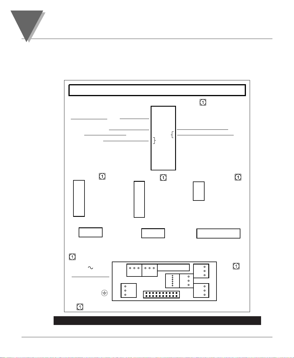
4.2 REAR OF THE METER
The following is a brief description of each part of the rear of the meter. The
label on the top of the mounting sleeve (not the case) identifies the location
of the connectors found at the rear of the meter. Figure 4-2A & figure 4-2B
shows this label.
Figure 4-2A. AC Power - Connector Label for Rear Connectors
4
Parts of the Meter
10
VALLEY(V) 3
PEAK/VALLEY OR EXT RESET 5
RESET ALARMS AND/OR 9
P4 / RS232
6 N/C
5 COMM RTN
4 RX
3 TX
2 RTS
1 N/C
P6 / RELAY
1 2 3
DISPLAY HOLD 9
PRINT COMMAND 11
NONSTANDARD TX 13
P2 / CABLE CONNECTOR
TARE(T) 1
DIG RTN 7
+V EXT 15
SP2 17
AL2 19
P4 / RS485
6 N/C
5 B,-RX
4 A, +RX
3 COMM RTN
2 B, -TX/RX
1 A, +TX/RX
P7 / RELAY
1 2 3
2 PEAK(P)
4 SWLIN2
6 PUSH TO CAL
8 +5V
LOCKOUT EEPROM &
10
MENU PUSH BUTTON
11
12 NONSTANDARD RX
14 PUSH TO CAL
16 SP1
18 AL1
20 RTN EXT
P5 / ANALOG OUT
1 RETURN
2 4-20MA
3 0-10V
* NOT AVAILBALE
WITH=DC POWER
* P18 / 4RELAY
1 2 3 4 5 6
NO1
CM1
NC1
P8 / BCD (see manual for pinout) P9&P3 / SIGNAL IN
P1 / AC
POWER
LINE L
NUETRAL N
GND
CONNECT TO LOW VOLTAGE LIMITED ENERGY CIRCUITRY ONLY.
1
1
P1
P6
NO2
CM2
NC2
P7
P8 or P16
P4
1
P5
19
1
P2
1
NO3
CM3
NC3
NO4
CM4
NC4
+E
1
P9
1
P3
+S
- S
1
- E
+R
- R
Page 21
11
Parts of the Meter
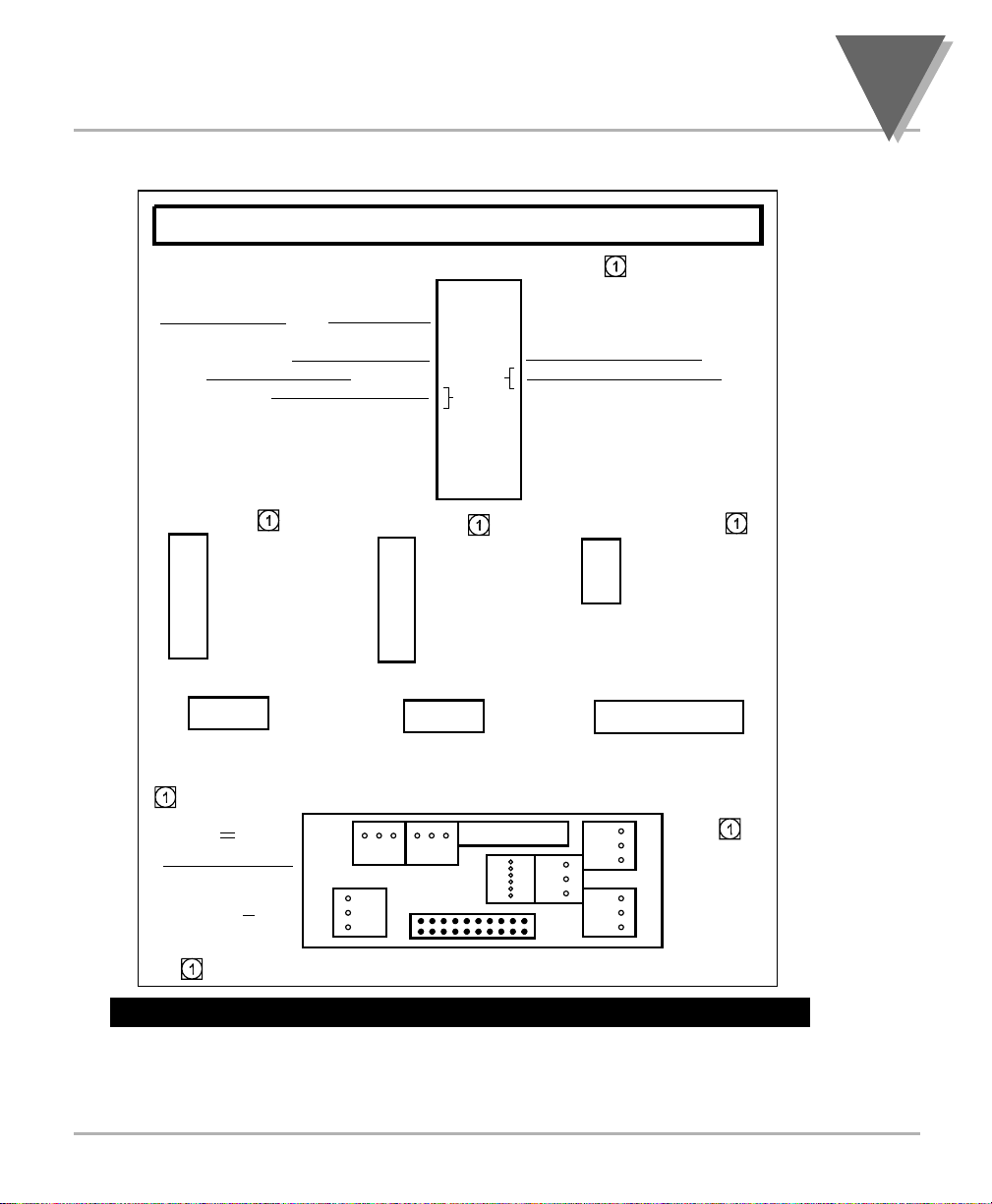
4
Figure 4-2B. DC Power - Connector Label for Rear Connectors
P2 / CABLE CONNECTOR
TARE(T) 1
VALLEY(V) 3
PEAK/VALLEY OR EXT RESET 5
DISPLAY HOLD 9
RESET ALARMS AND/OR 9
PRINT COMMAND 11
NONSTANDARD TX 13
P4 / RS232
6 N/C
5 COMM RTN
4 RX
3 TX
2 RTS
1 N/C
P6 / RELAY
1 2 3
DIG RTN 7
+V EXT 15
P4 / RS485
2 PEAK(P)
4 SWLIN2
6 PUSH TO CAL
8 +5V
LOCKOUT EEPROM &
10
MENU PUSH BUTTON
11
12 NONSTANDARD RX
14 PUSH TO CAL
16 SP1
SP2 17
AL2 19
6 N/C
5 B,-RX
4 A, +RX
3 COMM RTN
2 B, -TX/RX
1 A, +TX/RX
P7 / RELAY
1 2 3
18 AL1
20 RTN EXT
P5 / ANALOG OUT
1 RETURN
2 4-20MA
3 0-10V
* NOT AVAILBALE
WITH=DC POWER
* P18 / 4RELAY
1 2 3 4 5 6
NO1
CM1
NC1
P8 / BCD (see manual for pinout) P9&P3 / SIGNAL IN
P1 / DC
POWER
N/C
+
CONNECT TO LOW VOLTAGE LIMITED ENERGY CIRCUITRY ONLY.
1
1
P1
P6
NO2
CM2
NC2
P7
P8 or P16
P4
1
P5
19
1
P2
1
NO3
CM3
NC3
NO4
CM4
NC4
+E
1
P9
1
P3
+S
- S
1
- E
+R
- R
Page 22
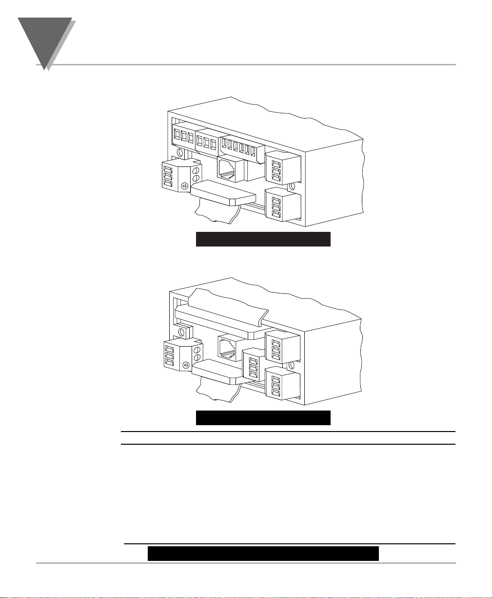
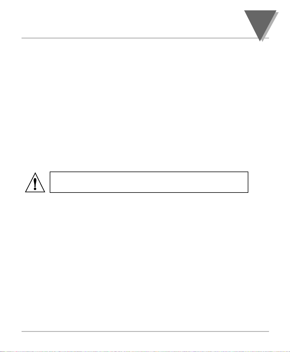
Figure 4-3 shows the rear of the meter with the optional 4-relay output board
and a serial communications board installed.
Figure 4-3. Rear View
Figure 4-4 shows the rear of the meter with the optional BCD output board
and a serial communications output board installed.
Figure 4-4. Rear View
CONNECTOR # DESCRIPTION
P1 AC Power Connector
P2 External I/O Connector
P3 Input Connector, –E, +R, –R
J4 Optional RS-232 or RS-485 Phone Jack Connector
P5 Optional Analog Out Connector
P6 Optional Form-C Relay #1 Connector
P7 Optional Form-C Relay #2 Connector
P8 Optional BCD Connector
P9 Input Connector, +E, +S, –S
P18 Optional Form-C Relay #3 and #4 Connector
TABLE 4-1 Rear Connector Descriptions
4
Parts of the Meter
12
P6
1
2
3
1
P1
L
1
2
N
3
1
P7
P18
1
2
2
3
3
4
5
6
J4
20
P2
1
2
P9
3
1
2
P3
3
U1
L1
P1
L
1
2
N
3
P8
U20
L20
J4
1
20
P2
1
2
P9
3
1
P5
2
3
1
2
P3
3
Page 23
5.1 CONDITIONS REQUIRING DISASSEMBLY
You may need to remove the sleeve or open the meter for several reasons:
1. To inspect the rating label on the case (not the same label as on the
sleeve) (Section 5.2.1).
2. To check or change the 115 V ac or 230 V ac or main board jumpers
(Sections 5.2.2 and 5.2.4).
3. To install optional output board(s) (Section 5.2.3).
4. To mount the meter in a panel (Section 5.2.5).
5.2 ASSEMBLY/DISASSEMBLY OPENING
OPENING THE METER
Your meter is fully assembled, but not wired. See Section 7 for wiring
connection for power and sensor inputs. In most cases, if you have ordered
optional boards with the meter, these boards will already be installed.
You will need to remove only the rear cover to complete wiring, but you will
have to open the meter to do one or more of the following:
WARNING!: You must disconnect and turn-off the power and connector
signals before accessing the unit and installing optional boards. Failure to do
so may result in injury!
a. Check or reconfigure the Transformer Jumpers on the Main Board so
that they correspond to your line voltage (W1 and W2 for 115 V ac, or
W3 for 230 V ac). See Section 5.2.2.
b. Install optional boards. See Section 5.2.3.
c. Access jumpers on the Main and optional boards. See Section 5.2.4.
13
Setup
5
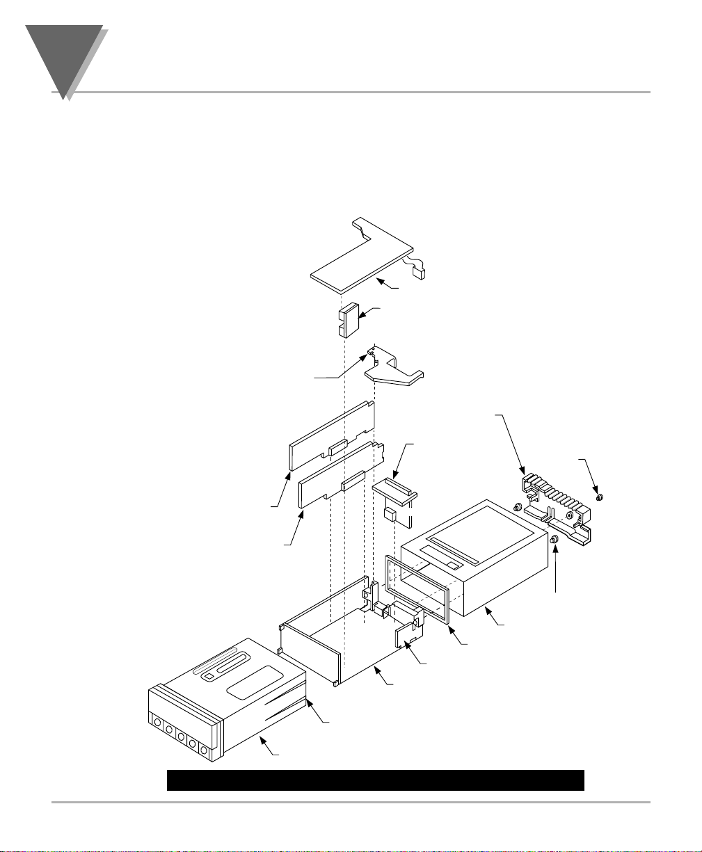
Page 24
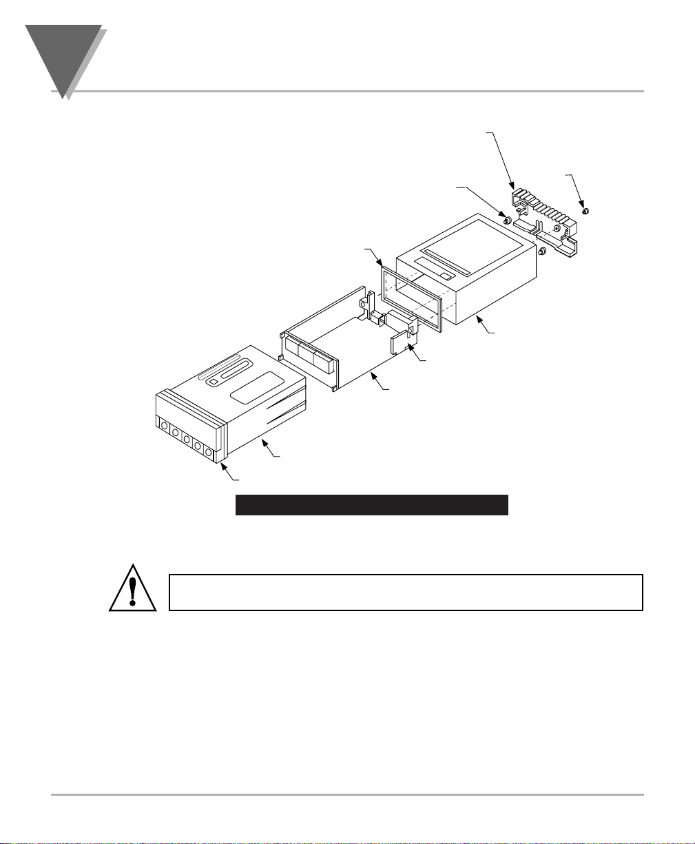
Figure 5-1. Meter Exploded View
Using Figures 5-1 as a guide, follow these simple instructions to open the
meter:
IMPORTANT: Turn-off the power and input signals from the unit before
proceeding. Failure to do so may result in injury!
1. Remove the cover mounting screw that secures the rear protective cover
to the meter, and remove the Rear Protective Cover.
If you are simply wiring the meter–but not checking jumpers or installing
or removing boards–this is as far as the meter needs to be
disassembled. Go to Section 5.2.1.
2. Remove all wiring connectors from the rear of the meter.
3. Remove the two thumbnuts that secure the case to the sleeve.
4. Remove the sleeve completely by sliding it back from the front bezel.
5
Setup
14
REAR
PROTECTIVE
COVER
COVER
MOUNTING
SCREW
THUMBNUTS
GASKET
SLEEVE
AC POWER BOARD
MAIN BOARD ASSY
CASE
BEZEL
Page 25
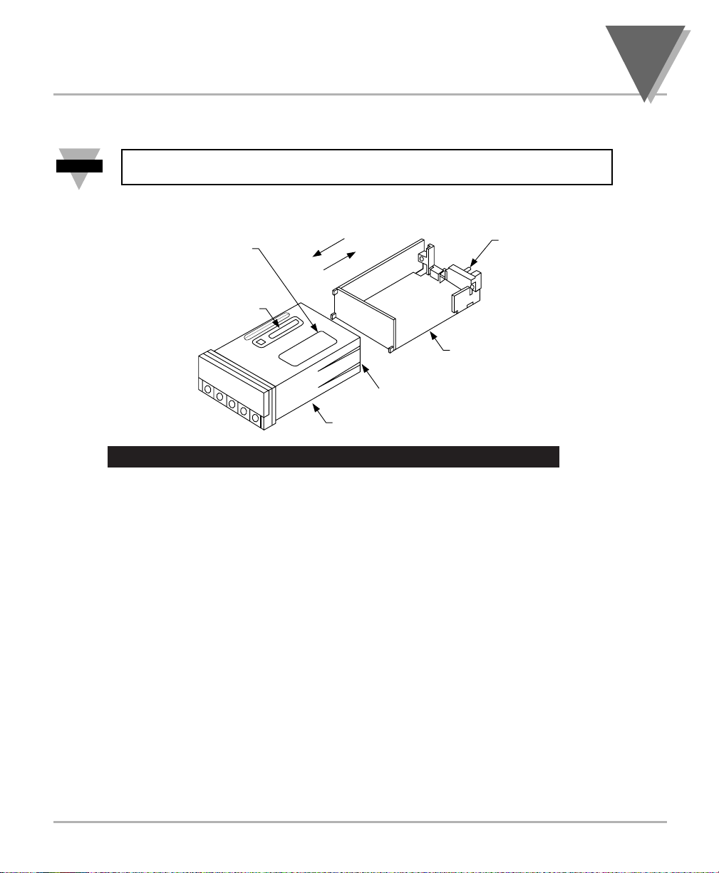
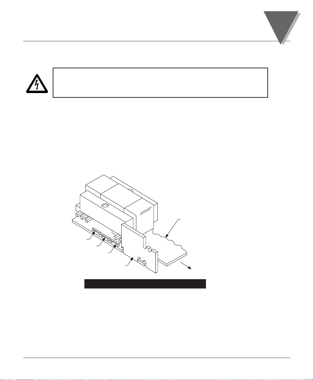
5. Using Figure 5-2 as a guide, bend the side-panel detents on the case
outward and pull the board assembly out of the case by the mounting
screw stem.
NOTE: From this point forward, these 5 steps are referred to as “Reveal the
main board”.
Figure 5-2. Board Assembly Removing/Installing Detail
The meter is now disassembled to the point where you can check and
configure jumpers and install boards.
REINSERTING THE MAIN BOARD ASSEMBLY INTO THE CASE
Reinsert the Main Board into the case once jumpers and optional boards
have been configured and installed.
Spread the side-panel detents of the case, and carefully slide the main
board all the way in.
15
Setup
5
Note
☞
PRODUCT
IDENTIFICATION
LABEL
SIGNAL INPUT
JUMPER LABEL
TO INSTALL
TO REMOVE
CASE
MOUNTING
SCREW
STEM
MAIN BOARD ASSY
BEND DETENTS OUTWARD
TO INSTALL MAIN BOARD
Page 26
5.2.1 Safety Precaution/Product ID Label
To look at the Rating/Product ID label on the case, you must follow the first
step as described in Section 5-2. Refer to Figure 5-2 for the location of the
Product Identification label.
The meter is protected in accordance with Class I of EN61010. Refer to
Safety Considerations page.
WARNING: If your meter is to be wired to sensors to control inputs that
could be hazardous potentials, these potentials will be carried to the 20-pin
output connector (P2) at the rear. They will also be present on the meter’s
circuit boards. Follow all instructions carefully BEFORE connecting the
meter to any source of power.
DO NOT contact any exposed metal parts, install optional board(s), change
jumpers, or in any way disassemble or assemble the meter while it is
connected to AC voltage.
Note the following information and guidelines for safe operation of your
meter:
Power Voltage
Your power source voltage rating should agree with the voltage under which
the meter has been configured to operate. The first thing you should do is
verify this.
The meter’s operating voltage is shown in the VOLTS: entry of the Product
Identification and Serial Number Label. It is located on the case, as shown in
Figure 5-2, and is clearly visible on the meter packing box.
5
Setup
16
Page 27
5.2.2 Main Board Power Jumpers
To check voltage jumpers or to change from 115 V ac to 230 V ac:
CAUTION: The meter has no power-on switch; it will be in operation as soon
as you apply power. To change the factory preset jumpers, disconnect the
power from the unit. Failure to do so may result in injury! The jumpers must
be changed by specifically trained personnel.
1. “Reveal the Main Board” (refer to Section 5.2, Disassembly).
2. Locate the main board assembly and position it in front of you the same
way as shown in Figure 5-3.
3. On the main board, locate the transformer jumpers W1, W2, and W3
near the transformer T1.
If your power requirement is 115 V ac, jumpers W1 and W2 should be
installed. (DO NOT INSTALL W3)
If your power requirement is 230 V ac, jumper W3 should be installed.
(DO NOT INSTALL W1 OR W2)
Figure 5-3. Transformer Jumpers
17
Setup
5
T1
W2
W3
W1
AC POWER
BOARD
MAIN
BOARD
REAR OF
METER
Page 28
5
Setup
18
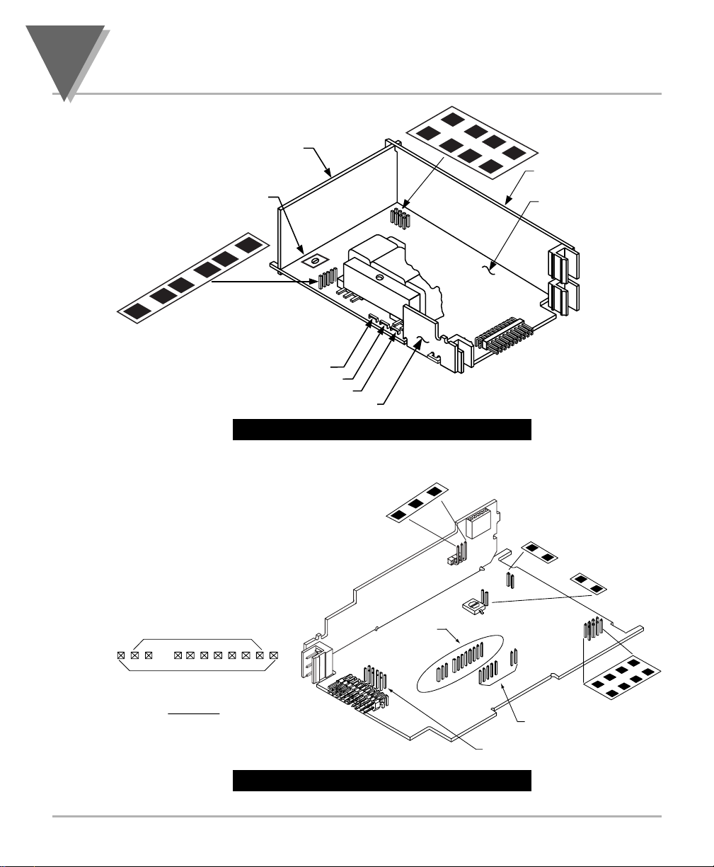
5.2.3 Printed Circuit Board(s) Installation
To install optional printed circuit board(s):
1. “Reveal the Main Board” (refer to Section 5.2, Disassembly).
2. Using Figure 5-4 as a reference, insert option board(s) into the
corresponding slot(s) on the main board. Each circuit board is
keyed to fit in it’s own position.
Figure 5-4. Optional Printed Circuit Board Locations
J20
BCD BOARD OR 4 RELAY BOARD
P20
P14
RETAINER
(ALWAYS USED
EXCEPT FOR
BCD OR 4 RELAY
OPTION)
P12
INTERCONNECT BOARD
(PART OF BCD ASSY)
P10
(4 RELAY BOARD ONLY)
REAR
PROTECTIVE
COVER
DUAL RELAY
BOARD
COVER
MOUNTING
SCREW
P11
ISOLATED ANALOG
OUTPUT BOARD
RS-232/RS-485 BOARD
J12 J11
J14
BEND DETENTS OUTWARD
TO INSTALL MAIN BOARD
CASE
P10
J10
AC POWER BOARD
MAIN BOARD ASSY
GASKET
THUMBNUTS
SLEEVE
Page 29
19
Setup
5
5.2.4 How to Access Jumpers
To gain access to jumper S1 and S2 used to configure input type remove the
mounting sleeve. The jumpers may be accessed through the slot in the
case.
To gain access to jumpers on the main board for power, excitation and
lockout selection:
1. “Reveal the main board” (refer to Section 5.2, Disassembly).
NOTE: To access the S1 and S2 jumpers on the Signal Input Board, you
only need to remove the mounting sleeve.
2. To re-assemble the meter, follow the steps in reverse order.
Figures 5-5 through 5-13 show the layout of the seven (7) printed circuit
boards with respective jumper blocks, where applicable, used in the meter.
Figures 5-7 through 5-13 show the optional boards.
Figure 5-5. Signal Input Board
Note
☞
K
B
E
A
G
A
B
S1
D
F
C
M
H
L
J
TOP VIEWS
R
P
STU
Q
N
V
S2
J9
J3
Page 30
5
Setup
20
Figure 5-6. ac-Powered Main Board
Figure 5-7. dc-Powered Main Board
D
DISPLAY
BD
R39
S4
B
A
C
T1
S3
C
B
A
SIGNAL INPUT BD
MAIN BD
J9
J3
J2
W2
W3
W1
AC POWER BD
J1
B
AA
1
S
PINS FOR RS 485
1
1A
ALL PINS FOR RS232A
DETAIL A
S4
SEE
11
DETAIL A
J10
J2
R34
J11
1A
1
PINS FOR RELAY
A
S5
S5
10
J12
PINS FOR
ANALOG OUT
A
S4
3
S
A B C D
3
S
Page 31

21
Setup
5
Figure 5-8. Relay Option Board
Figure 5-9. 4-Relay Option Board
NOTE: Both the Dual Relay Output Board and the 4 Relay Output Board can
be installed at J10. However, only one option board can be installed at a
time.
P7
P6
AB
C
E
P10
D
PIN 1
S1
4 RELAY BOARD
Note
PIN 1 OF CABLE
J10
PIN 1
MAIN BOARD
☞
Page 32

5
Setup
22
Figure 5-10. Analog Output Option Board
Figure 5-11. RS-232 Option Board
Figure 5-12. RS-485 Option Board
The RS-232 option board has been
updated. The figure shown is the
latest version.
Some older versions of the RS-232
cards are not compatible with
dc-powered
meters.
Check the J11 connector on the
main board to ensure it has a 12
position connector.
The RS-485 option board has been
updated. The figure shown is an
older version, the newer version is
the same figure as the RS-232
option card shown above.
The Analog option board has been
updated. The figure shown is the
latest version.
Some older versions of the analog
output cards are not compatible
with dc-powered
meters.
Check the J12 connector on the
main
board to ensure it has a 10
position connector.
S1-A does not
need to be
installed.
1
J5
S1
P12
0
1
1A
1
A
S1
A
S2
A
B
A
S1
S4
1
S
ABCDE
S3
2
S
4
S
1
1
P
1
1
6
3
S
4
J
1
A
1
1
S3
A
J4
S1
A
B
P11
A
S4
6
PIN 10
1
PIN 1
A
S2
Page 33

23
Setup
5
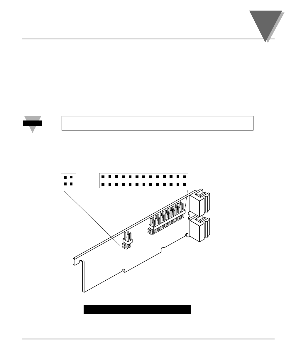
Figure 5-13. BCD Option Board
5.2.5 PANEL-MOUNT ASSEMBLY
The meter can be mounted in a panel so that the front of the meter is flush
with the vertical panel surface. Panel mounting can be seen as simply
“sandwiching” the panel between the inner case and the outer sleeve in the
last phases of assembly. Figure 5-14 shows the panel cutout dimensions,
and the dimensions for the panel thickness. It requires that the following
already be done:
1. Your line voltage rating has been checked against the meter rating on
the Product ID and serial number label on the meter case. See Section
5.2.1.
2. You have configured all jumpers–those on the main board as well as
those on any optional boards. See Section 5.2.2 for main board jumper
configuration and the appropriate sections for optional board jumper
configuration.
3. You have installed all optional boards and inserted the main board
assembly back into the case. See Section 5.2.3.
4. You have wired P1, the AC power connector, and P2 the input output
control connector; connectors are not installed in the meter, but are
ready to be installed. See Section 7.
5. You have wired all connectors for optional boards; connectors are not
connected to the meter, but are ready to be installed.
If all of these steps are done, use Figure 5-14 as a guide:
CAUTION: Connectors with the wiring connections will be installed after
mounting the unit.
S1
A A
J8
S2
U1
S4
A B
L1
S5
A
E
C
G
B
S6
A
S3
A B
A
S7
B
A
B
S8
J20
PIN 1
Page 34

5
Setup
24
Figure 5-14. Panel Mounting Assembly
6. Punch or cut a hole in the panel using the panel cutout dimensions in
Figure 5-14. Remove burrs and paint the panel as required.
7. Insert the panel-mount gasket around the rear of the case and slide it
forward to the bezel (if it’s not already in place).
8. Working from the front of the panel, insert the case assembly, rear end
first, all the way into the panel cutout such that the gasket firmly backs
the panel surface.
9. Working from the rear of the panel, slide the sleeve forward over the
case and up to the panel surface.
The panel should now be sandwiched between the bezel-backed gasket in
front and the sleeve in back.
10. Replace the thumbnuts that secure the sleeve tabs to the case.
PANEL THICKNESS
0.25 [6.4] MAX
0.03 [0.8] MIN
0.06
R
[1.5]
4PLCS
3.622 +0.032/-.000
[92.00 +0.81/-0.00]
1.772 +0.024/-.000
[45.00 +0.61/-0.00]
PANEL
REAR
PROTECTIVE
COVER
THUMBNUTS
COVER
MOUNTING
SCREW
METER
CASE
GASKET
SLEEVE
Page 35

WARNING: Do not “turn-on” the ac power and input signals until all
connections are connected to the meter.
11. Set P1, the AC power connector, aside and connect or reconnect all
other connectors to the back of the meter using Figures 4-3 and 4-4 in
Section 4.2 as guides.
Connect P1 last.
NOTE: The P1 connector is “keyed”; it is shaped in such a way that it fits
only the J1 male pins.
12. Replace the rear protective cover and secure it with the cover mounting
screw.
Your meter is now ready for operation and you can turn-on the power.
The meter display should light, and pass through “RESET 2” to run or
display mode. If the meter flashes an overscale or overload message, press
the ‘MENU’ button to advance to the configuration mode. Do not be
concerned about overloads (the +S input can stand 120 V continuously and
current inputs can handle ten times rated current).
25
Setup
5
Note
☞
Page 36

6
Jumper Positions
26
6.1 INTRODUCTION
This section is for the configuration and setup of your jumper positions for
readrate, unipolar or bipolar signal input, sensor input signal jumpers, sensor
excitation jumpers, pushbutton lockouts and lockout of lockout configuration
menus.
6.2 S1 JUMPER POSITIONS FOR READRATE AND UNIPOLAR OR
BIPOLAR INPUT(S)
The typical readrate for your meter is 3/per second. This requires that no
jumper has been installed in the S1A position and Input Configuration
(“IN CNF”) bit “INP.2” has been set to equal “0”. Your meter is capable of a
fast readrate of 13/per second. This requires that you install a jumper in the
S1A position and the Input Configuration (“IN CNF”) bit “INP.2” has been set
to equal “1”. Refer to Figure 6-1 for the location of the S1 jumpers.
The typical setting for your meter is unipolar. For unipolar input, no jumper is
installed in the S1B position and Input Configuration (“IN CNF”) bit “INP.3”
must be set to equal “0”. For bipolar inputs, install a jumper in S1B and set
Input Configuration (“IN CNF”) bit “INP.3” to equal “1”.
6.3 S2 JUMPER POSITIONS FOR INPUT RANGES
The following are the input signal jumper positions required to be installed in
the “S2” position on your meter for the CURRENT or VOLTAGE input ranges
you require. These jumper positions include those that are required for sensor excitation. Jumpers S2-N & S2-T are for either 10 Vdc or 24 Vdc sensor
excitation. To select desired excitation see Section 6.4. Refer to Figure 6-1
for the location of the S2 jumpers.
Figure 6-1. S1 and S2 Jumper Locations on Signal Input Board
M
H
G
K
L
J
TOP VIEWS
B
E
A
A
B
S1
D
F
C
R
P
STU
Q
N
V
S2
J9
J3
Page 37

27
Jumper Positions
6
VOLTAGE - UNIPOLAR
VOLTAGE - BIPOLAR
CURRENT
POTENTIOMETER
Jumpers for 0 to 100 mV range: (meter supplied excitation)
B
A
B
S2
S1
E
A
D
F
C
Jumpers for 0 to 1 V range: (meter supplied excitation)
B
A
B
S2
S1
E
A
D
F
C
Jumpers for 0 to 10 V range: (meter supplied excitation)
B
A
B
S2
S1
E
A
D
F
C
Jumpers for 0 to 100 V range: (meter supplied excitation)
B
A
B
S2
S1
E
A
D
F
C
Jumpers for -50 to +50 mV range: (meter supplied excitation)
B
A
B
S2
S1
Jumpers for -500 to +500 mV range: (meter supplied excitation)
A
B
S2
S1
E
A
D
F
C
B
E
A
D
F
C
K
M
H
G
G
G
G
G
G
L
J
K
M
H
L
J
K
M
H
L
J
K
M
H
L
J
K
M
H
L
J
K
M
H
L
J
R
P
STU
Q
N
R
P
STU
Q
N
R
P
STU
Q
N
R
P
STU
Q
N
R
P
STU
Q
N
R
P
STU
Q
N
V
V
V
V
V
V
Jumpers for -5 to +5 V range: (meter supplied excitation)
K
B
A
B
S2
S1
E
A
G
D
F
C
M
H
L
J
R
P
STU
Q
N
V
Jumpers for -50 to +50 V range: (meter supplied excitation)
K
B
A
B
S2
S1
E
A
G
D
F
C
M
H
L
J
R
P
STU
Q
N
V
Jumpers for 0-20 mA or 4-20 mA: (Factory preset value) (meter supplied excitation)
M
E
B
S2
A
A
B
S1
D
F
C
K
H
G
L
J
R
P
STU
Q
N
V
Jumpers for 0 to 10 V range: (using 10 Vdc drive)
K
B
A
B
S2
S1
E
A
G
D
F
C
M
H
L
J
R
P
STU
Q
N
V
Page 38

6
Jumper Positions
28
6.4 JUMPER SETTING(S) FOR SENSOR EXCITATION
6.4.1 JUMPER SETTING(S) FOR SENSOR EXCITATION- ac Powered Unit
Your ac-powered meter is capable of supplying either 1.5 to 11Vdc or 24 Vdc
sensor excitation. (refer to Figure 6-2.).
• For 1.5 to 11Vdc excitation, install S4A and C jumpers, then adjust the
potentiometer (R39) for proper voltage.
• For 24Vdc excitation, remove S4A and C jumpers and install S4B.
A
B
A
D
G
H
V
L
P
S
T
U
B
C
E
F
J
K
N
M
R
Q
S2
S1
24 Vdc meter excitation (S2N, S2T, omit S4A)
A
B
A
D
G
H
V
L
P
S
T
U
B
C
E
F
J
K
N
M
R
Q
S2
S1
10 Vdc meter excitation (S2N, S2T, & S4A)
A
B
A
D
G
H
V
L
P
S
T
U
B
C
E
F
J
K
N
M
R
Q
S2
S1
1.25 Vdc meter excitation (S2Q)
A
B
A
D
G
H
V
L
P
S
T
U
B
C
E
F
J
K
N
M
R
Q
S2
S1
160 µA meter excitation (S2P)
A
B
A
D
G
H
V
L
P
S
T
U
B
C
E
F
J
K
N
M
R
Q
S2
S1
1.6 mA meter excitation (S2P, S2V)
Page 39

29
Jumper Positions
6
Figure 6-2. ac-Powered Main Board Jumper Positions S3 and S4
NOTE: S3B should NOT be installed. This jumper is only used when
recalibrating the meter (e.g. an annual, careful performance by the
calibration lab). When this jumper is installed, calibration coefficients can be
changed via digital communications.
S4 On ac-powered units, main board
S4B Installed For 24 Vdc excitation.
(S4A located in storage position).
S4A ,S4C Installed For 10 Vdc excitation.
S3 On ac-powered units, main board
S3A Installed Unlocks “MENU” button for programming.
S3B Omit See note below.
S3C Installed Unlocks lockout menu (L1 through L4).
S3D Installed Unlocks Front pushbuttons.
S3
C
B
A
SIGNAL INPUT BD
MAIN BD
J2
J1
S4
B
A
S4A shown in
storage position
DISPLAY
R39
C
BD
W2
W3
AC POWER BD
D
T1
W1
J9
J3
Note
☞
Page 40

6.4.2 JUMPER SETTING(S) FOR SENSOR EXCITATION - dc Powered Unit
Your dc-powered meter is capable of supplying either 1.25 to 12Vdc or
24 Vdc sensor excitation. (refer to Figure 6-3).
• For 1.25 to 12Vdc excitation, install S1A and S4A jumpers, then adjust
the potentiometer (R34) for proper voltage.
• For 24Vdc excitation, remove S4A jumpers and install S1B.
Figure 6-3. dc-Powered Main Board Jumper Positions S3 and S4
6
Jumper Positions
30
S1 On dc-powered unit, side power board
S1A Installed For 1.25 to 12 Vdc excitation at 120 mA
.
S1B Installed For 24 Vdc excitation at 35 mA.
S3, S4, S5 On dc-powered unit, main board
S3A Installed To store data and setup parameters in nonvolatile memory.
S3BOmitSee note in previous Section 6.4.1.
S3C Installed Unlocks lockout menu (L1 through L4).
S3D Installed Unlocks Front pushbuttons.
S4A Installed Along with the S1 jumper to program the excitation
output. Adjust excitation with R34 surface mount pot
from 1.25 to 12 volts, with an output current up to 120mA.
S4A Removed For 24 Vdc excitation.
(S4A located in storage position).
S5A Installed To enable the RESET front panel pushbutton.
S5A Removed To secure against unauthorized meter reset.
B
AA
S1
A
5
S
A
4
S
S3
D
C
B
A
S3
SEE
DETAIL A
0
J1
J2
5
S
4
S
4
3
R
1
J1
10
1A
J12
1
PINS FOR
ANALOG OUT
PINS FOR RELAY
Page 41

31
Signal and Power Input Connections
7
7.1 INTRODUCTION
The following describes how to connect your sensors to your meter with and
without sensor excitation and how to connect the AC power to your meter.
Prior to wiring the sensor to the meter, check with a multimeter that a proper
excitation exists.
WARNING: Do not connect ac power to your meter until you have
completed all input and output connections. Failure to do so may result in
injury! This device must only be installed electrically by specially trained
electrician with corresponding qualifications.
7.2 SIGNAL INPUT CONNECTIONS
The following figures (7-1 through 7-5) show the connections for voltage,
current and potentiometer inputs:
Figure 7-1. Current Input Without Sensor Excitation
Figure 7-2. Current Input With Sensor Excitation
(4-20mA)
(+)
(
-)
+ -
NC
1
+
S
–
S
P9
2
3
METER
NC
NC
NC
1
P3
2
3
(+)
(4-20mA)
(-)
JUMPER
USER
PROVIDED
NC
NC
+
+
–
–
+R
-R
E
S
S
E
1
P9
2
3
METER
1
P3
2
3
Page 42

7
Signal and Power Input Connections
32
Figure 7-3. Voltage Input Without Sensor Excitation
Figure 7-4. 3-Wire Voltage Input With Sensor Excitation
Figure 7-5 4-Wire Voltage Input With Sensor Excitation
+OUTPUT
VOLTAGE
-OUTPUT
NC
+
–
NC
NC
NC
1
S
S
P9
2
3
METER
1
P3
2
3
+
NC
+
–
–
+R
E
1
S
S
E
-R
P9
2
3
METER
1
P3
2
3
+EXCITATION
+OUTPUT
VOLTAGE
COMMON
JUMPER
USER
PROVIDED
+
+EXCITATION
+OUTPUT
VOLTAGE
-OUTPUT
E
1
+
S
–
S
P9
2
3
METER
-EXCITATION
JUMPER
USER
PROVIDED
NC
–
+R
E
1
P3
-R
2
3
Page 43

33
Signal and Power Input Connections
7
Figure 7-6. Potentiometer Connections with Internal Power
Supply and Ratio Measurement.
Figure 7-7 Potentiometer Connections With External Power
Supply and Ratio Measurement (Remove jumper S2-T)
7.3 CONNECTING MAIN POWER
Wire your power (from a wall socket or other source) to P1, the orange,
3-socket connector that plugs into the 3 pins on the left side as you view the
meter from the rear. The orange (power) connector must be wired according
to the following table (also refer to Figure 7-8):
USA EUROPE PIN # ON
WIRING WIRING ORANGE
CODE CODE CONNECTION CONNECTOR
Black Brown ~ AC Line (L) 1
White Blue ~ AC Neutral (N) 2
Green Green/Yellow ~ AC Protective
Earth Ground 3
METER
NC
+
S
–
S
–
E
+
R
P9
P3
1
2
3
1
2
3
-R
JUMPER
USER
PROVIDED
+R
+
E
+
S
–
S
-E
P9
P3
1
2
3
1
2
3
-R
JUMPER
USER
PROVIDED
METER
Page 44

7
Signal and Power Input Connections
34
Figure 7-8. AC Connector Wiring at P1
Connect your AC meter power as described above and as shown in Figure 7-8:
CAUTION: As mentioned in Section 5.2.2, the meter has no power ON/OFF
switch. The meter will be ON when power is applied.
WARNING: Do not connect ac power to your meter until you have
completed all input and output connections. Failure to do so may result in
injury! This device must only be installed electrically by specially trained
electrician with corresponding qualifications. The main power input to the
unit as well as the AC input signal to be measured must agree with the
wiring instruction. The meter is factory set to the power specified by the
customer at the time of ordering. The voltage is printed on the Product ID
Label.
Figure 7-9. DC Connector Wiring at P1
You are now ready to proceed with scaling your meter to display in engineering units as
described in Section 8.
1
2
3
P1
N
~AC LINE
~AC NEUTRAL
PROTECTIVE EARTH GND
L
L
FUSE
N
SWITCH
GREEN WIRE
EARTH
LINE
NEUTRAL
Check for proper Earth grounding
in the power distribution system (single phase).
1
2
3
P1
NC +DC -DC
NO CONNECTION
+DC
SHIELD/-DC RETURN
DC POWER
Page 45

35
Scaling to Display Engineering Units
8
METHOD FOR SCALING THE METER TO DISPLAY IN
ENGINEERING UNITS
8.1 INTRODUCTION
There are two basic methods for scaling your meter to display engineering
units; scaling by using measured input values or scaling without connecting
a sensor using assumed input values. Both methods use the Input Scale and
Offset (“IN.SC.OF”) method.
8.2 SETUP METER INPUT TYPE AND RANGE
If you have received your meter setup for your required input and do not
require changes or rescaling, skip this section entirely and proceed with the
normal use of your meter.
If you received your meter and you only require a scaling change, proceed
with the steps in Section 8.3.
If you received your meter and it has been configured for input other than
what you require, you must proceed with the following steps before rescaling
the display:
WARNING: You must set your jumper positions at the S1 and S2 positions
BEFORE proceeding. Refer to Section 6 for jumper positions.
Page 46

8
Scaling to Display Engineering Units
36
THEN PRESS UNTIL
(TO CHANGE DISPLAY
PRESS IF REQUIRED) SHOWS COMMENTS
‘MENU’ “INPUT” Press the ‘MENU’ button until
the display shows “INPUT”.
‘MIN’ “VOLT” Press the ‘MIN’ button and the
display will show some type of
input such as “VOLT”.
‘MAX’ “CURRNT” Press the ‘MAX’ button until
or the display shows a flashing
“VOLT” input type that you want such
or as “CURRNT”, “VOLT”
“POT” or “POT”.
‘MENU’ “CURRNT” Press the ‘MENU’ button to
store you selection. The display
will momentarily show “STORED”
only if a change has been made
and then will display your
selection such as “CURRNT”.
For Current Inputs:
‘MAX’ “4-20 mA” Press the ‘MAX’ button and
or the display shows a flashing
“0-20 mA” input range of 4-20 mA, or
“0-20 mA.” Press the ‘MAX’
button to select the 4-20 mA
input range.
For Voltage Inputs:
‘MAX’ Unipolar Press the ‘MAX’ button and
“100 mV”, the display will show a
“1 V”, flashing input voltage range
“10 V”,
“100 V”
Bipolar
“50 mV”,
“500 mV”,
“5 V”,
“50 V”
For Potentiometer Input:
No input range is selected.
‘MENU’ “STORED” Press the ‘MENU’ button to
then store your selection. The
“RDG.CNF”
display will momentarily show
“STORED” only if a change has
been made and then “RDG.CNF”
You are now ready to proceed with Input Scale and Offset (“IN.SC.OF”)
Page 47

37
Scaling to Display Engineering Units
8
8.3 SCALING YOUR METER USING 2-COORDINATE INPUT SCALE AND
OFFSET (IN.SC.OF) WITH SENSOR CONNECTED TO YOUR METER
The most accurate method for scaling your meter to display engineering
units is by connecting your sensor to your meter, apply two known loads,
record them as INPUT1 and INPUT2 respectively and use these numbers
for entry into 2-coordinate Input Scale and Offset (“IN.SC.OF”).
The typical factory calibration and configuration is for the meter to accept a
4-20 mA dc and scaled to display 0 to 020000.
An example would be a 2-wire transmitter that sends a signal of 4-20 mAdc.
With a signal input of 4 mA the display will show “000000” and with a signal
input of 20 mA this display will show “02000”. However, the output signal
from your transmitter may be something like 3.98 mA and 19.99 mA. Using
Input Scale and Offset (“IN.SC.OF”) you can configure your meter to
accurately display your required engineering units.
NOTE: Although the full span input of your sensor signal is preferred for
maximum resolution, you may record any two points within the signal span
for scaling accurately into engineering units.
The following will walk you step by step in configuring your meter for scaling
your meter using the Input Scale and Offset (“IN.SC.OF”) procedure.
Note
☞
Page 48

8
Scaling to Display Engineering Units
38
8.3.1 SETTING INPUT CONFIGURATION (“IN CNF”)
THEN PRESS UNTIL
(TO CHANGE DISPLAY
PRESS IF REQUIRED) SHOWS COMMENTS
‘MENU’ “IN CNF” Press the ‘MENU’ button until
the display shows “IN CNF”.
‘MIN’ “INP.3=0” Press the ‘MIN’ button until the
display shows “INP.3=0” or
“INP.3=1”.
‘MAX’ “INP.3=0” Press the ‘MAX’ button to select
“INP.3=0”- Unipolar input for
current, voltage and
potentiometer inputs.
or
‘MAX’ “INP.3=1” Press the ‘MAX’ button to select
“INP.3=1”- Bipolar input for
voltage or potentiometer inputs.
‘MIN’ “INP.6=0” Press the ‘MIN’ button until
or the display “INP.6=0” or
“INP.6=1” “INP.6=1”.
‘MAX’ “INP.6=1” Press the ‘MAX’ button until the
display shows “INP.6=1” to
enable Input Scale and Offset
(“IN.SC.OF”).
‘MENU’ “IN.SC.OF” Press the ‘MENU’ button to
store your selection and the
display will momentarily show
“STORED” then “IN.SC.OF”.
If you need to re-scale your meter, you must proceed with the following
steps:
Page 49

39
Scaling to Display Engineering Units
8
8.3.2 SCALING YOUR METER WITH YOUR SENSOR CONNECTED
Before proceeding, you must first apply a low input (“INPUT1”) and a high
input (“INPUT 2”) into your meter and record the exact display shown. As
explained in Section 8.3, the display you will be recording will be 0 and
100000 if your meter has not been changed from the typical factory setup
and calibration. The following is an example using the numbers below as the
recorded input displayed on the meter. You should use the numbers you
have recorded:
Low input: 4 milliamps
Meter display (“INPUT 1”): 000000.
High input: 20 milliamps
Meter display (“INPUT 2”): 020000.
Note: If you are using an input signal that is reverse acting (e.g. 20-4 mA),
then the 20 mA reading would be “INPUT1” and the 4 mA reading would be
“INPUT 2”.
In addition to recording your display readings for your two inputs, you must
also decide what you want these inputs to display on your meter.
In order to simplify this (especially if you want to display numbers to the right
of the decimal point position), you should think of your meter as a process
indicator and your decimal point as being passive or cosmetic.
As an example, if you wanted your display to read 0.000 to 68.000, you
would record and enter your “READ 1” number as 000000. and your “READ
2” number as 068000. Then after storing these numbers, you would then
place your decimal point position (refer to Section 8.3.4) so that your display
would show 0.000 to 68.000.
Record your “INPUT1” and “READ 1” numbers, and your “INPUT2” and
“READ 2” numbers, record them below and proceed as follows:
INPUT1 = ________________ 000003.
READ 1 = ________________ 000000.
INPUT2 = ________________ 020018.
READ 2 = ________________ 068000.
For the purpose of this example, we will use the numbers described above
for the following procedure:
Note
☞
Page 50

8
Scaling to Display Engineering Units
40
THEN PRESS UNTIL
(TO CHANGE DISPLAY
PRESS IF REQUIRED) SHOWS COMMENTS
‘MENU’ “IN.SC.OF” Press the ‘MENU’ button until
the display shows “IN.SC.OF”
Input Scale and Offset.
‘MIN’ “INPUT1” Press the ‘MIN’ button and the
display will show “INPUT1”.
‘MIN’ “XXXXXX” Press the ‘MIN’ button and the
display will show some 6 digit
number.
‘MAX’ ‘MIN’ “000003.” Using the ‘MAX’ button to
change the value of the flashing
digit and the ‘MIN’ button to
scroll to the next digit to the
right, enter your “INPUT1”
number on the display.
‘MENU’ “READ 1” Press the ‘MENU’ button and
the display will show “READ 1”.
‘MIN’ “XXXXXX” Press the ‘MIN’ button and the
display will show some 6-digit
number.
‘MAX’ ‘MIN’ “000000.” Using the ‘MAX’ button to
change the value of the flashing
digit and the ‘MIN’ button to
scroll to the next digit to the
light, enter the engineering
value that you want your
“INPUT1” number to display on
the meter.
‘MENU’ “INPUT2” Press the ‘MENU’ button and
the display will show “INPUT2”.
‘MIN’ “XXXXXX” Press the ‘MIN’ button and the
display will show some 6-digit
number,
‘MAX’ ‘MIN’ “100018.” Using the ‘MAX’ button to
change the value of the flashing
digit and the ‘MIN’ button to
scroll to the next digit to the
right, enter your “INPUT 2”
number on the display.
Page 51

41
Scaling to Display Engineering Units
8
THEN PRESS UNTIL
(TO CHANGE DISPLAY
PRESS IF REQUIRED) SHOWS COMMENTS
‘MENU’ “READ 2” Press the ‘MENU’ button and
the display will show “READ 2”.
‘MIN’ “XXXXXX” Press the ‘MIN’ button and the
display will show some 6-digit
number.
‘MAX’ ‘MIN’ “068000.” Using the ‘MAX’ button to
change the value of the flashing
digit and the ‘MIN’ button to
scroll to the next digit to the
right, enter the engineering
value you want your “INPUT 2”
to display.
‘MENU’ “STORED” Press the ‘MENU’ button to
store your selection and the
display will momentarily show
“STORED” then “DEC PT”.
Now you are ready to position your decimal point position by completing the
following steps:
Page 52

8
Scaling to Display Engineering Units
42
8.3.3 TO SELECT DECIMAL POINT POSITION (DEC PT)
The following is the procedure for selecting your decimal point position.
THEN PRESS UNTIL
(TO CHANGE DISPLAY
PRESS IF REQUIRED) SHOWS COMMENTS
‘MENU’ “DEC PT” Press the ‘MENU’ button until
the display shows “DEC PT”.
‘MIN’ ‘MAX’ “FFF.FFF” Press the ‘MIN’ button and the
display will show “FFFFFF.” or
the previously selected position.
Press the ‘MAX’ button to select
the decimal point position you
require, the meter displays the
previously selected decimal
point location within the “F’s”
‘MENU’ “CNT BY” Press the ‘MENU’ button to
store your decimal point
selection and the meter will
momentarily display “STORED”
only if you have made a
change, and then “CNT BY”.
‘RESET’ ‘RESET’ “RESET2” Press the ‘RESET’ button two
then the times. The display will
Measured momentarily show “RESET2”
Value and then will display the
currently measured values,
Your meter is now calibrated. If you need to offset your zero reading on your
meter after calibration, you must proceed with the following steps:
Page 53

43
Scaling to Display Engineering Units
8
8.3.4 ENTERING ZERO OFFSET NUMBERS
The RDG OF (Reading Offset) menu item should be used if the meter shows
a nonzero reading with zero input. The offset value zeroes the display by
canceling out the nonzero reading.
If your meter displays a positive reading at zero input, you must enter a
negative offset value. If your meter displays a negative reading at zero input,
you must enter a positive offset value.
If you are using an active decimal point (RDG.2=0), your offset value will be
the negative of the display reading at zero point.
If you are using the more common independent decimal point (the factory
setting, RDG.2=1), follow these instructions display reading to the
appropriate offset value:
1. Note the display reading at zero input, ignoring the decimal point. This
reading represents the count value - the number of whole counts that
need to be offset,
2. Shift the count value to the left side of the decimal point.
3. If the count value is positive, make it negative by replacing the leading
digit (the left-most digit) with a minus sign. If the count value is negative,
make it positive by replacing the negative sign with a zero.
Example 1: Your meter displays 000.003 when the input is zero. The count
value is 000003. Shift this value to the left side of the decimal point: 003.000.
Change the leading zero to a minus sign: -03.000. This is the “converted
offset value” you will use for configuring RDG OF.
Example 2: Your meter displays -00.003 when the input is zero. The count
value is -00003. Shift this value to the left side of the decimal point: -03.000.
Change the leading minus sign to a zero: 003.000. This is the “converted
offset value” you will use for configuring RDG OF.
If the nonzero reading is fluctuating between two numbers, convert the
smaller count value to the offset value, then add a 5 just right of the decimal
point. This adds half a count to the offset. For example, the display is
fluctuating between 00.0001 and 00.0002. Calculate the offset using the
000001 count value. The converted offset value is -1.0000. Add a 5 to the
right of the decimal point: -the final offset value is -1.5000.
Page 54

8
Scaling to Display Engineering Units
44
THEN PRESS UNTIL
(TO CHANGE DISPLAY
PRESS IF REQUIRED) SHOWS COMMENTS
‘MENU’ “RDG OF” Press the ‘MENU’ button until
the display shows “RDG OF”.
‘MIN’ “000000.” Press the ‘MIN’ button and the
display will show the last offset
entered.
‘MIN’ ‘MAX’ “XXXXXX” Use the ‘MIN’ to move to each
digit and the ‘MAX’ button to
change the flashing digits value
and enter your zero offset
number.
‘MENU’ “STORED” Press the ‘MENU’
then button to store
“IN CNF” your selection. The display will
momentarily show “STORED”
then “IN CNF”.
‘RESET’ ‘RESET’ “RESET2” Press the ‘RESET’
the then button two times. The
Measured display will momentarily
Value show “RESET2” and you will
display the currently measured
values.
NOTE: If after zeroing the display with RDG OF, the reading again drifts from
zero, the required offset value is the sum of the current RDG OF value and
the current converted offset value. The examples below illustrate the
calculation of required offset values when using an independent decimal. If
you are using an active decimal point, the current converted offset value is
simply the negative value of the display reading.
Example 1: You use a RDG OF value of -1.0000 to zero the meter. The next
morning, the meter displays 00.0008 at zero input; you need to rezero. The
current count value is 000008; shifting this value to the left of the decimal
makes it 08.0000, and making the value negative makes it -8.0000. The
required RDG OF value is the sum of the current RDG OF value (-1.0000)
and the current converted offset value (-8.0000):
-1.0000 + -8.0000 = -9.0000
Note
☞
Page 55

45
Scaling to Display Engineering Units
8
Example: You use a RDG OF value of -1.0000 to zero the meter. The next
morning, the meter displays -0.0008 at zero input; you need to rezero. The
current count value is -00008; shifting this value to the left of the decimal
makes it -8.0000, and making the value positive makes it 08.0000. The
required RDG OF value is sum of the current RDG OF value (-1.0000) and
the current converted offset value (08.0000):
-1.0000 + 08.0000 = 07.0000
If you require further configuration(s) for your specific application, refer to
sections 9 through 21.
NOTE: Should you receive an error code of any kind while configuring your
meter, refer to Section 17 - Troubleshooting - Display Messages and
Troubleshooting Guide.
8.4 SCALING YOUR METER WITHOUT CONNECTING A SENSOR USING
CALCULATED VALUES
Your meter can be scaled without connecting a sensor and taking measured
values rising Input Scale and Offset (“IN.SC.OF”).
The typical configuration and scaling of your meter is 4-20 mAdc input with a
display equal to 0 to 100000. If your meter has not been rescaled and your
input is 4-20 mAdc, you can use the factory scaling “0” as your “INPUT1”
and “100000” as your “INPUT2” and proceed with the step by step
procedure in Section 8.4.1.
If you need to change your input signal, you must rescale your meter as
described in the following steps:
8.4.1 PREPARING YOUR METER FOR SCALING WITH INPUT SCALE AND
OFFSET
If you are changing your input signal you must follow the instruction for
installing the correct jumper positions as described in Section 6 and the
sensor connections as described in Section 7.
WARNING: Do not connect your AC meter power until all input jumpers and
sensor input connections are completed. Failure to do so could result in
damage to your sensor and/or the meter.
The following procedure will direct you step by step in preparing your meter
for rescaling using Input Scale and Offset (“IN.SC.OF”)
Note
☞
Page 56

8
Scaling to Display Engineering Units
46
THEN PRESS UNTIL
(TO CHANGE DISPLAY
PRESS IF REQUIRED) SHOWS COMMENTS
‘MENU’ “IN.SC.OF” Press the ‘MENU’ button until
the display shows “IN.SC.OF”
Input Scale and Offset.
‘MIN’ “INPUT1” Press the ‘MIN’ button and the
display will show “INPUT1”.
‘MIN’ “XXXXXX” Press the ‘MIN’ button and the
display will show some 6 digit
number.
‘MAX’ ‘MIN’ “000000.” Using the ‘MAX’ button to
change the value of the
flashing digit and the ‘MIN’
button to scroll to the next digit
to the right, enter “000000.” on
the display.
‘MENU’ “READ 1” Press the ‘MENU’ button and
the display will show “READ 1”.
‘MIN’ “XXXXXX” Press the ‘MIN’ button and the
display will show some 6-digit
number.
‘MAX’ ‘MIN’ “000000.” Using the ‘MAX’ button to
change the value of the flashing
digit and the ‘MIN’ button to
scroll to the next digit to the
right, enter “000000” on the
meter.
‘MENU’ “INPUT2” Press the ‘MENU’ button and
the display will show “INPUT2”.
‘MIN’ “XXXXXX” Press the ‘MIN’ button and the
display will show some 6-digit
number.
Page 57

47
Scaling to Display Engineering Units
8
THEN PRESS UNTIL
(TO CHANGE DISPLAY
PRESS IF REQUIRED) SHOWS COMMENTS
‘MAX’ ‘MIN’ “020000.” Using the ‘MAX’ button to
change the value of the flashing
digit and the ‘MIN’ button to
scroll to the next digit to the
right, enter “020000.” on the
display.
‘MENU’ “READ 2” Press the ‘MENU’ button and
the display will show “READ 2”.
‘MIN’ “XXXXXX” Press the ‘MIN’ button and the
display will show some 6-digit
number.
‘MAX’ ‘MIN’ “100000.” Using the ‘MAX’ button to
change the value of the flashing
digit and the ‘MIN’ button to
scroll to the next digit to the
right, enter “100000.” on the
display.
‘MENU’ “STORED” Press the ‘MENU’ button to
store your selection and the
display will momentarily show
“STORED” then “DEC PT”.
Proceed with the following steps for positioning your decimal point position:
THEN PRESS UNTIL
(TO CHANGE DISPLAY
PRESS IF REQUIRED) SHOWS COMMENTS
‘MENU’ “DEC PT” Press the ‘MENU’ button until
the display shows “DEC PT”.
‘MIN’ ‘MAX’ “FFF.FFF” Press the ‘MIN’ button and the
display will show “FFFFFF.” or
the previously selected position.
Press the ‘MAX’ button to
select the decimal point position
you require, the meter displays
the previously selected decimal
Point location within the “F’s”.
‘MENU’ “CNT BY” Press the ‘MENU’ button to
store your decimal point
selection and the meter will
momentarily display “STORED”
only if you have made a change
and then “CNT BY”.
You are now ready to scale your meter rising Input Scale and Offset
(“IN.SC.OF”) without connecting a sensor or signal source to your meter.
Page 58

8
Scaling to Display Engineering Units
48
8.4.2 SCALING YOUR METER
Scaling your Meter without a sensor or a signal source connected is easily
accomplished by using one of the calculated scale factors as shown in
Figure 8-1.
These calculated scale factors are the numbers that your meter would
display if you connected a signal source.
You must complete the procedure for preparing your meter for scaling as
described in Section 8.4.1. Failure to complete this procedure will result in
erroneous readings.
INPUT SIGNAL LOW VALUE HIGH VALUE
0-20 mA 000000 020000
4-20 mA 000000 020000
± 50 mV -50000 050000
± 500 mV -50000 050000
0-20 mV 000000 020000
0-30 mV 000000 030000
0-50 mV 000000 050000
0-100 mV 000000 100000
0-1 V 000000 100000
0-5 V 000000 050000
1-5 V 010000 050000
1-6 V 010000 060000
0-10 V 000000 100000
0-50 V 000000 050000
0-100 V 000000 100000
+/-5 V -50000 050000
+/-50 V -50000 050000
Figure 8-1 . Factory Calculated Scale Factors
Page 59

49
Scaling to Display Engineering Units
8
For the purpose of this procedure, we will use an input of 1-5 Vdc and scale
the meter to display 0 to 2500.0.
The calculated scale factors can now be used to scale your meter to display
in engineering units using Input Scale and Offset (“IN.SC.OF”) as follows:
Record your “INPUT1” and “READ 1” numbers, and your “INPUT2” and
“READ 2” numbers, record them below and proceed as follows:
Example
INPUT1 = ________________ 010000.
READ 1 = ________________ 000000.
INPUT2 = ________________ 050000.
READ 2 = ________________ 025000.
Page 60

8
Scaling to Display Engineering Units
50
THEN PRESS UNTIL
(TO CHANGE DISPLAY
PRESS IF REQUIRED) SHOWS COMMENTS
‘MENU’ “IN.SC.OF” Press the ‘MENU’ button until
the display shows “IN.SC.OF”
Input Scale and Offset.
‘MIN’ “INPUT1” Press the ‘MIN’ button and the
display will show “INPUT1”,
‘MIN’ “XXXXXX” Press the ‘MIN’ button and the
display will show some 6-digit
number.
‘MAX’ ‘MIN’ “010000.” Using the ‘MAX’ button to
change the value of the flashing
digit and the ‘MIN’ button to
scroll to the next digit to the
right, enter your “INPUT1”
number on the display.
‘MENU’ “READ 1” Press the ‘MENU’ button on the
display will show ‘READ 1”.
‘MIN’ “XXXXXX” Press the ‘MIN’ button and the
display will show some 6-digit
number.
‘MAX’ ‘MIN’ “000000.” Using the ‘MAX’ button to
change the value of the flashing
digit and the ‘MIN’ button to
scroll to the next digit to the
right, enter the engineering
value that you want your
“INPUT1” number to display on
the meter.
‘MENU’ “INPUT2” Press the ‘MENU’ button and
the display will show “INPUT2”.
‘MIN’ “XXXXXX” Press the ‘MIN’ button and the
display will show some 6-digit
number.
‘MAX’ ‘MIN’ “050000.” Using the ‘MAX’ button to
change the value of the flashing
digit and the ‘MIN’ button to
scroll to the next digit to the
right, enter your “INPUT 2”
number on the display.
Page 61

51
Scaling to Display Engineering Units
8
THEN PRESS UNTIL
(TO CHANGE DISPLAY
PRESS IF REQUIRED) SHOWS COMMENTS
‘MENU’ “READ 2” Press the ‘MENU’ button and
the display will show ‘READ 2”.
‘MIN’ “XXXXXX” Press the ‘MIN’ button and the
display will show some 6-digit
number.
‘MAX’ ‘MIN’ “025000.” Using the ‘MAX’ button to
change the value of the flashing
digit and the ‘MIN’ button to
scroll to the next digit to the
right, enter the engineering
value, you want your “INPUT 2”
to display.
‘MENU’ “STORED” Press the ‘MENU’ button to
store your selection and the
display will momentarily show
“STORED” then “DEC PT”.
Now you are ready to position your decimal point position by completing the
following steps:
Page 62

8
Scaling to Display Engineering Units
52
8.4.3 TO SELECT DECIMAL POINT POSITION
The following is the procedure for selecting your decimal point position.
THEN PRESS UNTIL
(TO CHANGE DISPLAY
PRESS IF REQUIRED) SHOWS COMMENTS
‘MENU’ “DEC PT” Press the ‘MENU’ button until
the display shows “DEC PT”.
‘MIN’ ‘MAX’ “FFFFF.F” Press the ‘MIN’ button and the
display will show “FFFFFF.” or
the previously selected position,
Press the ‘MAX’ Button to
select the decimal point position
you require, the meter displays
the previously selected decimal
point location within the “F’s”.
‘MENU’ “CNT BY” Press the ‘MENU’ button to
store your decimal point
selection and the meter will
momentarily display “STORED”
only if you have made a change
and then “CNT BY”.
‘RESET’ ‘RESET’ “RESET2” Press the ‘RESET’
then the button two times. The
Measured display will momentarily
Value show “RESET2” then will
display the currently measured
values.
Your meter is now calibrated. If you need to offset your zero reading on your
meter after calibration, you must proceed with the following steps:
Page 63

53
Scaling to Display Engineering Units
8
THEN PRESS UNTIL
(TO CHANGE DISPLAY
PRESS IF REQUIRED) SHOWS COMMENTS
‘MENU’ “RDG OF” Press the ‘MENU’ button until
the display shows “RDG OF”.
‘MIN’ “000000.” Press the ‘MIN’ button and the
display will show the last offset
entered.
If your meter displays an offset, which is a positive number, you must enter a
negative “-” offset number into Reading Offset (“RDG OF”). An example
would be if your zero input shows “20” on your meter display, you would
enter “-00020” in Reading Offset (“RDG OF”) and if your zero input shows a
negative “-20” you would enter a positive 000020 in Reading Offset
(“RDG OF”).
THEN PRESS UNTIL
(TO CHANGE DISPLAY
PRESS IF REQUIRED) SHOWS COMMENTS
‘MIN’ ‘MAX’ “XXXXXX” Use the ‘MIN’ button to move to
each digit and the ‘MAX’ button
to change the flashing digits
value and enter your zero offset
number.
‘MENU’ “STORED” Press the ‘MENU’
then button to store your
“IN CNF” selection. The display will
momentarily show “STORED”
then “IN CNF”.
‘RESET’ ‘RESET’ “RESET2” Press the ‘RESET’
then the button two times. The
Measured display will momentarily
Value show “RESET2” and then will
display the currently measured
values.
Page 64

8
Scaling to Display Engineering Units
54
8.4.4 ENTERING ZERO OFFSET NUMBERS
The RDG OF (Reading Offset) menu item should be used if the meter shows
a nonzero reading with zero input. The offset value zeroes the display by
canceling out the nonzero reading.
If your meter displays a positive reading at zero input, you must enter a
negative offset value. If your meter displays a negative reading at zero input,
you must enter a positive offset value.
If you are using an active decimal point (RDG.2=0), your offset value will be
the negative of the display reading at zero point.
If you are using the more common independent decimal point (the -factory
setting, RDG.2=1), follow these instructions to convert the display reading to
the appropriate offset value:
1. Note the display reading at zero input, ignoring the decimal point. This
reading represents the count value - the number of whole counts that
need to be Offset.
2. Shift the count value to the left side of the decimal point.
3. If the count value is positive, make it negative by replacing the leading
digit (the left-most digit) with a minus sign. If the count value is negative,
make it positive by replacing the negative sign with a zero.
Example 1: Your meter displays, 000.003 when the input is zero. The count
value is 000003. Shift this value to the left side of the decimal point: 003.000.
Change the leading zero to a minus sign: -03.000. This is the “converted
offset value” you will use for configuring RDG OF.
Example 2: Your meter displays -00.003 when the input is zero. The count
value is -00003. Shift this value to the left side of the decimal point: -03.000.
Change the leading minus sign to a zero: 003.000. This is the “converted
offset value” you will use for configuring RDG OF.
If the nonzero reading is fluctuating between two numbers, convert the
smaller count value to the offset value, then add a 5 just right of the decimal
point. This adds half a count to the offset. For example, the display is
fluctuating between 00.0001 and 00.0002.
Calculate the offset using the 000001 count value. The converted offset
value is -1.0000. Add a 5 to the right of the decimal point: the final offset
value is -1.5000.
Page 65

55
Scaling to Display Engineering Units
8
THEN PRESS UNTIL
(TO CHANGE DISPLAY
PRESS IF REQUIRED) SHOWS COMMENTS
‘MENU’ “RDG OF” Press the ‘MENU’ button until
the display shows “RDG OF”.
‘MIN’ “000000.” Press the ‘MIN’ button and the
display will show the last offset
entered.
‘MIN’ ‘MAX’ “XXXXXX” Use the ‘MIN’ to move to each
digit and the ‘MAX’ button to
change the flashing digits value
and enter your zero offset
number.
‘MENU’ “STORED” Press the ‘MENU’
then button to store your
“IN CNF” selection. The display will
momentarily show “STORED”
then “IN CNF”.
‘RESET’ ‘RESET’ “RESET2” Press the ‘RESET’
then the button two times. The
Measured display will momentarily
Value show “RESET2” and then will
display the currently measured
values.
NOTE: If after zeroing the display with RDG OF, the reading again drifts from
zero, the required offset value is the sum of the current RDG OF value and
the current converted offset value. The examples below illustrate the
calculation of required offset values when using an independent decimal. If
you are using an active decimal point, the current converted offset value is
simply the negative value of the display reading.
Note
☞
Page 66

8
Scaling to Display Engineering Units
56
Example 1: You use a RDG OF value of -1.0000 to zero the meter. The next
morning, the meter displays 00.0008 at zero input; you need to rezero. The
current count value is 000008; shifting this value to the left of the decimal
makes it 08.0000, and making the value negative makes it -8.0000. The
required RDG OF value is the sum of the current RDG OF value (-1.0000)
and the current converted offset value (-8.0000):
-1.0000 + -8,0000 = -9,0000
Example 2: You use a RDG OF value of -1.0000 to zero the meter. The next
morning, the meter displays -0.0008 at zero input; you need to rezero. The
current count value is -00008; shifting this value to the left of the decimal
makes it -8.0000, and making the value positive makes it 08.0000. The
required RDG OF value is sum of the current RDG OF value (-1.0000) and
the current converted offset value (08.0000):
-1.0000 + 08.0000 = 07.0000
If you require further configuration(s) for your specific application, refer to
Sections 9 through 21.
NOTE: Should you receive an error code of any kind while configuring your
meter, refer to Section 17 - Troubleshooting - Display Messages and
Troubleshooting Guide.
Note
☞
Page 67

57
Meter Function Menus
9
EXPLANATION OF LOCKOUT CONFIGURATIONS AND
METER FUNCTION MENUS
HOW TO USE THE TABLES IN SECTION 9
MIN/MAX/MENU These are the buttons on the meter you are to
press to access the parameters given in the
same column.
MAIN MENU/ These are headings for the table columns.
SUBMENU:
DISPLAYED These are parameters seen on the display
INFORMATION: after pressing either ‘MIN’, ‘MAX’, or ‘MENU’
button(s).
NOTE: If you press the ‘RESET’ button two times while the meter is in the
run mode, all Setpoints, Alarms, Peak & Valley will be reset and the meter
will begin new measurements.
If you press the ‘RESET’ button one time while in the configuration mode,
you will move one MAIN MENU backwards and any selection will not be
saved. If you press the ‘RESET’ button two times while in the configuration
mode, you will reset the meter and only those menu items saved by pressing
the ‘MENU’ button will be saved.
9.1 Individual Lockout Information
To restrict access to different parameters of the program in the meter, you
may want to lockout parts of the meter. When you lock out a parameter, it
will no longer appear when you scroll through the menu. To lock out specific
parameters of the meter (setpoint, scaling), refer to the following tables.
Once set (to unlock useful features for a given application and to lock out
any features), these four “L1C”, “L2C”, “L3C”, and “L4C” can be rapidly
skipped over by pressing the ‘MENU’ button four times.
Note
☞
Page 68

9
Meter Function Menus
58
MENU MIN/MAX*
BUTTON BUTTON
MAIN MENU SUB MENU CONDITION
“L1 CNF”: LOCKOUT CONFIGURATION #1
“L1C.1=0” Setpoint 1 change unlocked.
“L1C.1=1” Setpoint 1 change locked out.
“L1C.2=0” Setpoint 2 change unlocked.
“L1C.2=1” Setpoint 2 change locked out.
“L1C.3=0” Setpoint 3 (Alarm 1) change unlocked.
“L1C.3=1” Setpoint 3 (Alarm 1) change locked out.
“L1C.4=0
” Setpoint #4 (Alarm 2) change unlocked.
“L1C.4=1” Setpoint #4 (Alarm 2) change locked out.
“L1C.5=0” Valley-value (LO RDG) display is permitted.
“L1C.5=1” Displays microprocessor revision.
“L1C.6=0” Peak-value (HI RDG) display is permitted.
“L1C.6=1” Peak-value (HI RDG) display is not
permitted.
“L1C.7=0” INPUT CLASS (CURRENT VOLTAGE or
POT) can be selected.
“L1C.7=1” INPUT CLASS is locked out.
“L1C.8=0” INPUT TYPE (such as 0-20 mA, 4-20 mA,
0-100 mV, 0-10 Vdc, etc.) can be selected.
“L1C.8=1” INPUT TYPE is locked out.
*The ‘MIN’ button allows you to sequence through L1C.1, L1C.2, L1C.3,
L1C.4, L1C.5, L1C.6, L1C.7 and L1C.8.
The ‘MAX’ button allows you to select the “0” or “1” state for each “L1C”
condition.
The ‘MENU’ button stores the selected values for all “L1C” condition(s)
changed and advances the meter to “L2 CNF”. Do not press the ‘MENU’
button after each change within the submenu or the meter will advance to
the next menu item.
Every underlined “0” or “1” state is the factory preset value.
Page 69

59
Meter Function Menus
9
MENU MIN/MAX*
BUTTON BUTTON
MAIN MENU SUB MENU CONDITION
“L2 CNF”: LOCKOUT CONFIGURATION #2
“L2C.1=0” RDG.CNF (scale/offset method and display
features) may be chosen.
“L2C.1=1” RDG.CNF (scale/offset method and display
features) is locked out.
“L2C.2=0” Either RDG SC (computed input-to-display
scale factor)
or
RD.SC.OF (two data points, which
determine the reading scale/offset) may be
entered.
“L2C.2=1” Either RDG SC (computed input-to-display
scale factor)
or
RD.SC.OF (two data points, which
determine the reading scale/offset) is
locked out.
“L2C.3=0” RDG OF (offset computed in display digits)
may be entered.
“L2C.3=1” RDG OF (offset computed in display digits)
is locked out.
“L2C.4=0
” INP.CNF (meter rates, front-end features,
prelinearizing scale/offset) may be chosen.
“L2C.4=1” INP.CNF (meter rates, front-end features,
prelinearizing scale/offset) may not be
locked out.
“L2C.5=0” IN.SC.OF (two data points for additional
scale/offset) may be entered.
“L2C.5=1” IN.SC.OF (two data points for additional
scale/offset) may not be entered.
“L2C.6=0” DEC PT (decimal-point location) may be
chosen
“L2C.6=1” DEC PT (decimal-point location) may not
be chosen.
continued next page
Page 70

9
Meter Function Menus
60
MENU MIN/MAX*
BUTTON BUTTON
MAIN MENU SUB MENU CONDITION
“L2 CNF”
“L2C.7=0” CNT BY (round off of display) can be
specified.
“L2C.7=1” CNT BY (round off of display) cannot be
specified.
“L2C.8=0” FIL CNF (adaptive/fixed filtering and for
which output(s)) can be chosen.
“L2C.8=1” FIL CNF (adaptive/fixed filtering and for
which output(s)) cannot be chosen.
* The ‘MIN’ button allows you to sequence through L2C.1, L2C.2, L2C.3,
L2C.4, L2C.5, L2C.6, L2C.7, and L2C.8.
The ‘MAX’ button allows you to select the “0” or “1” state for each “L2C”
condition.
The ‘MENU’ button stores the selected values for all “L2C” condition(s)
changed and advances the meter to “L3 CNF”. Do not press the ‘MENU’
button after each change within the submenu or the meter will advance to
the next menu item.
Every underlined “0” or “1” state is the factory preset value.
MENU MIN/MAX*
BUTTON BUTTON
MAIN MENU SUB MENU CONDITION
“L3 CNF”: LOCKOUT CONFIGURATION#3
“L3C.1=0
” FIL TI (# of samples in average) can be
chosen.
“L3C.1=1” FIL TI (# of samples in average) cannot be
locked out.
“L3C.2=0” SP CNF (mode of action of setpoints 1 & 2
LEDs, transistors and relays) can be
selected.
“L3C.2=1” SP CNF (mode of action of setpoints 1 & 2
LEDs, transistors and relays) cannot be
locked out.
“L3C.3=0
” AL CNF (mode of action of Setpoints 3 & 4,
often used as alarms) can be locked out.
Page 71

61
Meter Function Menus
9
MENU MIN/MAX*
BUTTON BUTTON
MAIN MENU SUB MENU CONDITION
“L3 CNF” “L3C.3=1” AL CNF (mode of action of setpoints 3 & 4,
often used as alarms) cannot be locked
out.
“L3C.4=0” AL FNC (Setpoints 3 & 4 independent or
ganged with Setpoints 1 and 2) can be
selected.
“L3C.4=1” AL FNC (Setpoints 3 & 4 independent or
ganged with Setpoints 1 and 2) cannot be
accessed.
“L3C.5=0” AL RDG (# of out-of-range readings before
trip of setpoints 3 & 4) can be selected.
“L3C.5=1” AL RDG (# of out-of-range readings before
trip of setpoints 3 & 4) cannot be accessed.
“L3C.6=0” SP DB (hysteresis or deadband of
Setpoints and Alarms) can be specified.
“L3C.6=1” SP DB (hysteresis (deadband) of Setpoints
and Alarms) cannot be accessed.
“L3C.7=0
” OUT.CNF (analog & BCD outputs, setpoint
display flashing) can be specified.
“L3C.7=1” OUT.CNF (analog & BCD outputs, setpoint
display flashing) cannot be accessed.
“L3C.8=0” OT.SC.OF (2-data-point method for
independent analog-output scale/offset)
can be entered.
“L3C.8=1” OT.SC.OF (2-data-point method for
independent analog-output scale/offset)
cannot be accessed.
* The ‘MIN’ button allows you to sequence through L3C.1, L3C.2, L3C.3,
L3C.4, L3C.5, L3C.6, L3C.7, and L3C.8.
The ‘MAX’ button allows you to select the “0” or “1” state for each “L3C”
condition.
The ‘MENU’ button stores the selected values for all “L3C” condition(s)
changed and advances the meter to “L4 CNF”. Do not press the ‘MENU’
button after each change within the submenu or the meter will advance to
the next menu item.
Every underlined “0” or “1” state is the factory preset value.
Page 72

9
Meter Function Menus
62
MENU MIN/MAX*
BUTTON BUTTON
MAIN MENU SUB MENU CONDITION
“L4 CNF”: LOCKOUT CONFIGURATION #4
“L4C.1=0” BAUD (communication rate) can be chosen.
“L4C.1=1” BAUD (communication rate) cannot be
accessed.
“L4C.2=0” SER.CNF (parity/stop-bit length) is
selectable.
“L4C.2=1” SER.CNF (parity/stop-bit length) is not
selectable.
“L4C.3=0” ADDRES (meter address # on a multipoint
bus) can be changed.
“L4C.3=1” ADDRES (meter address # on a multipoint
bus) cannot be accessed.
“L4C.4=0
” DAT FT & BUS FT (format of datA stream
and bus interaction for digital
communications) can be altered.
“L4C.4=1” DAT FT & BUS FT (format of data stream
and bus interaction for digital
communications) cannot be accessed.
“L4C.5=0
” SERCNT (interval # of readings for the
automatic digital output of meter) can be
changed.
“L4C.5=1” SERCNT (interval # of readings for the
automatic digital output of meter) cannot be
accessed.
“L4C.6=0
” Analog output trim input can be entered.
“L4C.6=1” Analog output trim input cannot be entered.
* The ‘MIN’ button allows you to sequence through L4C.1, L4C.2, L4C.3,
L4C.4, L4C.5 and L4C.6.
The ‘MAX’ button allows you to select the “0” or “1” state for each “L4C”
condition.
The ‘MENU’ button stores the selected values for all “L4C” condition(s)
changed and advances the meter to “INPUT”. Do not press the ‘MENU’
button after each change within the submenu or the meter will advance to
the next menu item.
Every underlined “0” or “1” state is the factory preset value.
Page 73

63
Meter Function Menus
9
9.2 METER FUNCTION MENUS
9.2.1 Input
By pressing the ‘MAX’ and ‘MENU’ buttons you can select and then store
respectively either “CURRNT”, “VOLTAGE” or “POT” (input type). Refer to
the chart below to go the next level of programming of the meter.
MENU MIN/MAX*
BUTTON BUTTON
MAIN MENU SUB MENU DESCRIPTION
SIGNAL TYPE
“CURRNT” “0-20 mA” DC current
“4-20 mA”
“VOLT” “100 mV” Unipolar DC voltage
“1 V”
“10 V”
“100 V”
Bipolar DC voltage
“50 mV”
“500 mV”
“5 V”
“50 V”
“POT” No input selection is made.
9.2.2 RDG.CNF (Reading Configuration)
Reading configuration is used to select:
• reading scale and offset (direct vs 2-point) [RDG.1]
• active or independent decimal point [RDG.2]
• display brightness [RDG.3]
• leading zero suppression on your meter display [RDG.4]
Direct scale and Offset: these two values are used in the straight line
equation, y = mx + b. (RD.SC.OF)
Display = m times input plus b or [ m (input) + b ] (where m is the RDG SC
and b is the RDG OF).
RDG.6 enables or disables (RD.SC.OF), (RDG,SC), (RDG.OF).
The 2-data-point method allows the user to use two known points to convert
from one scale to another. For example, to convert from degrees Fahrenheit
to degrees Celsius, enter two (2) known points, such as 32°F = 0°C and 0°F
= 17.77°C. The meter will automatically compute scale and offset and
display the correct value.
Page 74

9
Meter Function Menus
64
MENU MIN/MAX/MENU *
BUTTON BUTTON
MAIN MENU SUB MENU DESCRIPTION
“RDG.CNF”: READING CONFIGURATION
Reading Scale & Offset:
“RDG.1=0” Direct Format
“RDG.1=1” 2-Coordinate format
Decimal point effect:
“RDG.2=0” Active
“RDG.2=1” Independent
Display Brightness:
“RDG.3=0” Normal
“RDG.3=1” 50% of Normal
Leading Zeros on Display:
“RDG.4=0” Displayed
“RDG.4=1” Not Displayed
“RDG.5=0” Unit of Temperature:
“RDG.5=1” NOT USED WITH
“RDG.5=2” PROCESS
Reading Scale & Offset Functions:
“RDG.6=0”
Disables Reading Scale and Offset
(RDG SC=1.0, RDG OF=0.0)
“RDG.6=1” Enables Reading Scale and Offset
(Uses scale and offset values entered
by user)
Resetting Mode:
“RDG.7=0” Grounding P2-5 causes
Hard Reset (RESET 2)
“RDG.7=1” Grounding P2-5 causes Peak/Valley
(HI/LO) Reset
* The ‘MIN’ button allows you to sequence through RDG.1, RDG.2, RDG.3,
RDG.4, RDG.5, RDG.6, and RDG.7.
The ‘MAX’ button allows you to select the “0” or “1” state for each “RDG”
condition.
The ‘MENU’ button stores the selected values for all “RDG.CNF”
condition(s) changed and advances the meter to “RD SC”. Do not press the
‘MENU’ button after each change within the submenu or the meter will
advance to the next menu item.
Every underlined “0” or “1” state is the factory preset value.
Page 75

65
Meter Function Menus
9
9.2.3 RDG SC (Reading Scale) And RDG OF (Reading Offset)
Typically, this would be used only when you cannot connect a known load to
your meter, you require a display with 3 or more positions to the right of the
decimal point position, you have scaled your meter using Input Scale and
Offset (“IN.SC.OF”) and want to enter a constant multiplying factor, or you
have an extremely large offset.
If “RDG.1=0” were chosen, then you go automatically into “RDG SC” and
“RDG OF” where:
“RDG SC” is reading scale from -99999 to +499999 where you set the
display to “1.00000” and “RDG OF” is reading offset from -99999 to 999999
when you set the display to “000000”.
When “RDG SC” is displayed, press the ‘MIN’ button to see the previouslyset value. Process measurement scale is set to “1.00000” using the
‘MIN/MAX’ buttons. Store by pressing the ‘MENU’ button.
For “RDG OF”, you may choose to enter a reference temperature offset here
(e.g., “-100.00”) so that the display will read deviation of the input from the
boiling point (or some other temperature).
If “RDG.1 = 1” were chosen, then you go automatically into “RD.SC.OF”.
Direct reading offset “RDG OF” now has programmable decimal point
position. This makes the decimal point independent of the display decimal
point and allows larger offset values.
Note
☞
Page 76

9
Meter Function Menus
66
MENU MIN/MAX
BUTTON MIN/MAX* /MENU**
MAIN BUTTON BUTTON
MENU SUB MENU 1 SUB MENU 2 DESCRIPTION
“RD.SC.OF”: READING SCALE & OFFSET
INPUT 1 Item #1 of Coordinate #1
000000. Enter the first value displayed
(“00000.0”) by the meter.
READ 1 Item #2 of Coordinate #1.
000000. Enter first desired value.
(“00000.0”)
INPUT 2 Item #1 of Coordinate #2.
000000. Enter the second value
(“10000.0”
) displayed by the meter.
READ 2 Item #2 of Coordinate #2.
000000. Enter second
(“10000.0”
) desired value.
* The ‘MIN’ button allows you to sequence through “INPUT 1”, “READ 1”,
“INPUT 2”, and “READ 2” headings.
The ‘MAX’ button sends you to the value corresponding to “INPUT 1”,
“READ 1”, “INPUT 2”, or “READ 2” so you can change it (go to the SUB
MENU 2 item).
** The ‘MIN’ button allows you to step through the digits of the applicable
number being changed.
The ‘MAX’ button changes the value of the digit to be displayed.
The ‘MENU’ button stores the selected values for each input required in
“RD.SC.OF”. After the last value (“READ 2”) has been entered and the
‘MENU’ button is pressed, the meter display will advance to “IN CNF”.
Every underlined item is the factory preset value.
Meter now stores all scale and offset values for “IN.SC.OF”, “RD.SC.OF”,
and “OT.SC.OF”.
The meter will display previously input values when entering these menus. If
system decimal point changes, all values will be modified accordingly; if
overflow occurs meter will flash that parameter with 999999.
Note
☞
Page 77

67
Meter Function Menus
9
9.2.4 IN CNF (Input Configuration)
Input configuration is used to select:
• 50 or 60 Hz line frequency [INP.1]
• slow or fast read rate [INP.2]
• unipolar or bipolar inputs
• cold junction compensation [INP.5]
INP.1 and INP.2 are related to each other. If your power requirements require
50 Hz, you can have optimum integration in FAST read mode (12/sec). In the
FAST mode, you need a jumper in the S1A position on the vertical Signal
Input Board. If you set the SLOW read rate, this jumper should be removed
to avoid overloading the integrator. SLOW read rate produces less noise.
MIN/MAX
MENU /MENU *
BUTTON BUTTON
MAIN MENU SUB MENU DESCRIPTION
“IN CNF”: INPUT CONFIGURATIONS
Line Frequency:
“INP
.1=0” 60 Hz
“INP.1=1” 50 Hz
Read Rate:
“INP.2=0”Slow
“INP.2=1” Fast
Input Voltage:
“INP.3=0” Unipolar
“INP.3=1” Bipolar
Transmitter Type:
“INP.4=0” No Transmitter
“INP.4=1” Not used
“INP.4=2” Not used
Process Mode:
“INP.5=0” Must be set to this bit
“INP.5=1” Not Used
IN.SC.OF:
“INP
.6=0” Disabled
“INP.6=1” Enabled
Type of Reading: (not used for
Temperature, set “INP.7 = 0”)
“INP
.7=0” Non Ratiometric
“INP.7=1” Not used
Page 78

9
Meter Function Menus
68
* The ‘MIN’ button allows you to sequence through INP.1, INP.2, INP.3, INP.4,
INP.5, INP.6, and INP.7.
The ‘MAX’ button allows you to select the “0” or “1” state for each “INP”
condition.
The ‘MENU’ button stores the selected values for all “IN CNF” condition(s)
changed and advances the meter to “IN.SC.OF”. Do not press the ‘MENU’
button after each change within the submenu or the meter will advance to
the next menu item.
Every underlined “0” or “1” state is the factory preset value.
9.2.5 IN.SC.OF (Input Scale and Offset)
Refer to Section 8 for a detailed discussion of this feature.
Input scale and offset is typically used when you want to scale your meter
(using two input data points):
MENU MIN/MAX/
BUTTON MIN/MAX * MENU **
MAIN BUTTON BUTTON
MENU SUB MENU 1 SUB MENU 2 DESCRIPTION
“IN.SC.OF”: INPUT SCALE OFFSET
Input scale and offset in
2-Coordinate Format
INPUT 1 Item #1 of Coordinate #1.
000000. Enter the first value displayed
(“000000.
”) by the meter.
READ 1 Item #2 of Coordinate #1.
000000. Enter first desired value.
(“000000.”)
INPUT 2 Item #1 of Coordinate #2.
000000. Enter the second
(“100000.
”) value displayed by the meter.
READ 2 Item #2 of Coordinate #2.
000000. Enter second desired value.
(“100000.
”)
* The ‘MIN’ button allows you to sequence through “INPUT 1”, “READ 1”,
“INPUT 2”, and “READ 2” headings.
The ‘MAX’ button sends you to the value that corresponds to “INPUT 1”,
“READ 1”, “INPUT 2”, or “READ 2” so you can change it (go to the SUB
MENU 2 item).
Page 79

69
Meter Function Menus
9
** The ‘MIN’ button allows you to sequence through the digits of the applicable
number being changed.
The ‘MAX’ button changes the value of the digit to be displayed.
The ‘MENU’ button stores the selected values for each input required in
“IN.SC.OF”. After the last value (“READ 2”) has been entered and the
‘MENU’ button is pressed, the meter display will advance to “DEC PT”.
Pressing the ‘MENU’ button allows you go to the next SUB MENU 1 item
automatically.
After changing the last value at the bottom of the chart, pressing the ‘MENU’
button once more stores everything that was changed and advances the
meter to the next configuration (“DEC PT”).
Every underlined item is the factory preset value.
Page 80

9
Meter Function Menus
70
9.2.6 DEC PT (Decimal Point)
Refer to Section 8 for a detailed discussion of this feature.
Decimal point is used to select the resolution of your meter display such as
in one degree, tenths of a degree, hundredths of a degree or more.
If “ERR 01” is displayed, check that “RDG OF” is within the display range.
MENU MIN/MAX/MENU *
BUTTON BUTTON
MAIN MENU CONDITION DESCRIPTION
“DEC PT”: DECIMAL POINT POSITION
“FFFFFF
.” Position 1
“FFFFF.F” Position 2
“FFFF.FF” Position 3
“FFF.FFF” Position 4
“FF.FFFF” Position 5
“F.FFFFF” Position 6
* Press the ‘MIN’ button to show all “F’s” on the display.
Press the ‘MAX’ button to move the decimal point.
Press the ‘MENU’ button to store the decimal point location and the meter
will advance to “CNT BY”.
The underlined item is the factory preset value.
Page 81

71
Meter Function Menus
9
9.2.7 CNT BY (Count By)
Count by is used to round off the meter values by 1’s, 2’s, 5’s, 10’s, 20’s,
50’s, or 100’s. This feature is normally set to “001” so that the display shows
all possible values for the least-significant digit.
If the combination of input-signal noise and selected resolution is high,
however, your meter can round off the display to the nearest 2, 5, 10, 20, 50
or even 100 digits. This can eliminate annoying display jitter without
introducing any filter time delays.
MENU MIN/MAX/MENU *
BUTTON BUTTON
MAIN MENU SUB MENU DESCRIPTION
“CNT BY”: COUNT BY ROUNDING OFF THE VALUE
“001”
“002” (the decimal point
“005” position is ignored)
“010”
“020”
“050”
“100”
* Press the ‘MIN’ button to show “001”, “002”, “005”, “010”, “020”, “050”, or
“100”.
Press the ‘MAX’ button to select one of the above.
Press the ‘MENU’ button to store the Count By number and the meter will
advance to “FIL.CNF”.
The underlined item is the factory preset value.
Page 82

9
Meter Function Menus
72
9.2.8 FIL.CNF (Filter Configuration)
Filter configuration is used to select:
• Adaptive Bandwidth Control (ABC) filtering or moving average filter [FIL.1]
• whether the value displayed on the meter is filtered or unfiltered [FIL.2]
• whether the value sent to the optional analog output is filtered or unfiltered
[FIL.3]
“FIL.1=0” for Adaptive Bandwidth Control (ABC filtering, which averages over
a larger number of samples when the input is not moving, but drops down to
no averaging for systematic input changes). “FIL.1=1” is for averaging over
a fixed number of samples. The number of samples to be used is selected
in “FIL TI”.
“FIL.3=0” removes the selected filtering from the analog output (if that option
is installed in your meter). “FIL.3=1” puts the selected filtering on that
output. Usually you choose “FIL.3=0”, relying on the signal conditioning
available at the device receiving the analog output data.
MIN/MAX/
MENU MENU *
BUTTON BUTTON
MAIN MENU SUB MENU DESCRIPTION
“FIL.CNF”: FILTER CONFIGURATION
Filter Type:
“FIL.1=0” ABC Filter
“FIL.1=1” Moving Average Filter
Value to be displayed:
“FIL.2=0” Unfiltered
“FIL.2=1” Filtered
Value to be transmitted
on Analog Output:
“FIL.3=0” Unfiltered
“FIL.3=1” Filtered
“FIL.3=2” Peak value
“FIL.3=3” Valley value
The ‘MIN’ button allows you to sequence through FIL.1, FIL.2, and FIL.3.
The ‘MAX’ button allows you to select the “0”, “1”, “2”, or “3” state for each
“FIL” condition.
The ‘MENU’ button stores the selected values for all “FIL.CNF” condition(s)
changed and advances the meter to “FIL TI”. Do not press the ‘MENU’
button after each change within the submenu or the meter will advance to
the next menu item.
Adaptive Bandwidth Control takes the average of the samples except when
the input is rapidly changing. Patent applied for.
Every underlined “0”, “1”, “2”, or “3” is the factory preset value.
Page 83

73
Meter Function Menus
9
9.2.9 FIL TI (Filter Time Constant)
Filter time constant is used to determine the number of readings the meter
will average before displaying an input value. The choices are 001, 002,
004, 008, 016, 032, 064, or 128.
For fixed filtering, the averaged number of samples is fixed; for Automatic
Bandwidth Control, the chosen value is the maximum number of samples in
the average computed by ABC when the input is not changing significantly
(ABC, for slowly-moving signals, filters by averaging the “TI” number of
samples, but follows signal changes rapidly by decreasing that averaging
number).
Pressing the ‘MENU’ button stores your selection and moves on to “RESET
1” and then to “RUN” (unless setpoints, outputs, or communications have
been unlocked for programming change)
MENU MIN/MAX/MENU *
BUTTON BUTTON
MAIN MENU SUB MENU DESCRIPTION
“FIL TI”: FILTER TIME CONSTANT
“001”
“002”
“004”
“008” Number of readings
“016” used in averaging.
“032”
“064
”
“128”
* Press the ‘MIN’ button to show “001”, “002”, “004”, “008”, “016”, “032”, “064”
or “128”.
Press the ‘MAX’ button to select one of the above.
Press the ‘MENU’ button to store the selection made and to advance the
meter to the next menu (“SP CNF”).
The underlined item is the factory preset value.
Page 84

9
Meter Function Menus
74
9.2.10 SP CNF (Setpoints 1 & 2 Configuration)
Refer to Section 10 for an in-depth discussion of these features.
Setpoint configuration is used to select:
• the active zone of each setpoint to above and below the setting
[SPC.1 & SPC.4]
• whether the open-collector output is on or off [SPC.2 & SPC.5]
• whether the reading compared with the setpoints is filtered or unfiltered
[SPC.3 & SPC.6]
• enabled or disabled setpoints [SPC.7]
• enabled or disabled setpoint LED displays [SPC.8]
MENU MIN/MAX/MENU *
BUTTON BUTTON
MAIN MENU SUB MENU DESCRIPTION
“SP CNF”: SETPOINTS 1 & 2 CONFIGURATIONS
Setpoint 1 Active Zone:
“SPC.1=0
” Above
“SPC.1=1” Below
Setpoint 1 open-collector or relay output
Active ON or OFF:
“SPC.2=0
”On
“SPC.2=1” Off
Filtered/unfiltered reading compared
with Setpoint 1 value:
“SPC.3=0” Unfiltered
“SPC.3=1” Filtered
Setpoint 2 Active zone:
“SPC.4=0” Above
“SPC.4=1” Below
Setpoint 2 open-collector or relay output
Active ON or OFF:
“SPC.5=0
”On
“SPC.5=1” Off
Filtered/unfiltered reading compared
with Setpoint 2 value:
“SPC.6=0” Unfiltered
“SPC.6=1
” Filtered
Setpoints 1 & 2 action:
“SPC.7=0” Enabled
“SPC.7=1” Disabled
Setpoint 1 & 2 LEDs action:
“SPC.8=0” Enabled
“SPC.8=1” Disabled
Page 85

75
Meter Function Menus
9
* The ‘MIN’ button allows you to sequence through SPC.1, SPC.2,
SPC.3, SPC.4, SPC.5, SPC.6, SPC.7 and SPC.8.
The ‘MAX’ button allows you to select the “0” or “1” state for each “SPC”
condition.
The ‘MENU’ button stores the selected values for each “SPC” condition
changed and advances the meter to the next configuration (“AL CNF”).
Every underlined “0” or “1” is the factory preset value.
9.2.11 AL CNF (Alarm Configuration)
Refer to Section 10 for an in-depth discussion of these features.
Alarm configuration is used to select:
• the active zone for each alarm point to above or below the
setting [ALC.1 & ALC.4]
• whether the open-collector output is on or off [ALC.2 & ALC.5]
• whether the readings compared with the alarm points are filtered or
unfiltered [ALC.3 & ALC.6]
• enabled or disabled alarm points [ALC.7]
MENU MIN/MAX/MENU *
BUTTON BUTTON
MAIN MENU SUB MENU DESCRIPTION
“AL CNF”: ALARMS 1 & 2 (SETPOINTS 3 & 4)
CONFIGURATIONS
Alarm 1 Active zone (Setpoint 3):
“ALC.1=0” Above
“ALC.1=1” Below
Alarm 1 open-collector or relay output
Active ON or OFF:
“ALC.2=0” On
“ALC.2=1” Off
Filtered/unfiltered reading compared
with Alarm 1 (Setpoint 3) value:
“ALC.3=0” Unfiltered
“ALC.3=1
” Filtered
Alarm 2 Active zone
(Setpoint 4):
“ALC.4=0
” Above
“ALC.4=1” Below
continued next page
Page 86

9
Meter Function Menus
76
MENU MIN/MAX/MENU *
BUTTON BUTTON
MAIN MENU SUB MENU DESCRIPTION
Alarm 2 open-collector or relay output
Active ON or OFF:
“ALC.5=0”On
“ALC.5=1” Off
Filtered/unfiltered reading compared
with Alarm 2 (Setpoint 4) value:
“ALC.6=0” Unfiltered
“ALC.6=1” Filtered
Alarms 1 & 2 (Setpoints 3 & 4) action
and LEDs:
“ALC.7=0” Enabled
“ALC.7=1” Disabled
Alarm reset at P2-11 connector:
“ALC.8=0” Disabled
“ALC.8=1” Enabled
* The ‘MIN’ button allows you to sequence through ALC.1, ALC.2, ALC.3,
ALC.4, ALC.5, ALC.6, ALC.7 and ALC.8.
The ‘MAX’ button allows you to select the “0” or “1” state for each “ALC”
condition.The ‘MENU’ button stores the selected values for each “ALC”
condition changed and advances the meter to the next configuration
(“AL FNC”).
Every underlined “0” or “1” is the factory preset value.
Page 87

77
Meter Function Menus
9
9.2.12 AL FNC (Alarm Function)
Refer to Section 10 for an in-depth discussion of these features.
Alarm function is used to select:
• whether the alarms are used in the process, high-deviation,
low-deviation or band deviation modes [ALF.1 & ALF.3]
• whether or not to latch the alarms [ALF.2 & ALF.4]
MENU MIN/MAX/MENU *
BUTTON BUTTON
MAIN MENU SUB MENU DESCRIPTION
“AL FNC”: ALARMS 1 & 2 FUNCTION
Alarm 1 State:
“ALF.1=0” Process Mode
“ALF.1=1” High Deviation Mode
“ALF.1=2” Low Deviation Mode
“ALF.1=3” Band Deviation Mode
Alarm 1 Latch Action:
“ALF.2=0” Unlatched
“ALF.2=1” Latched
Alarm 2 State:
“ALF.3=0” Process Mode. Process Mode
means the deadband is equally
above and below the setpoint.
“ALF.3=1” High Deviation Mode
“ALF.3=2” Low Deviation Mode
“ALF.3=3” Band Deviation Mode
Alarm 2 Latch Action:
“ALF.4=0” Unlatched
“ALF.4=1” Latched
* The ‘MIN’ button allows you to sequence through ALF.1, ALF.2, ALF.3 and
ALF.4.
The ‘MAX’ button allows you to select the “0”, “1”, “2”, or “3” state for each
“ALF” condition.
The ‘MENU’ button stores the selected values for each “ALF” condition
changed and advances the meter to the next configuration (“AL RDG”).
Every underlined item is the factory preset value.
Page 88

9
Meter Function Menus
78
9.2.13 AL RDG (Alarm Readings)
Refer to Section 10 for an in-depth discussion of these features.
Alarm reading is used to select the number of readings (from 01 to 15)
the meter must make prior to activating the alarms.
MENU MIN/MAX/MENU *
BUTTON BUTTON
MAIN MENU SUB MENU DESCRIPTION
“AL RDG”: ALARM NUMBER
OF READINGS
“00 00” Number of readings to
(“03 03
”) delay activation of Alarms
1 & 2 (from “01” to “15”)
(AL1), (AL2)
* Press the ‘MIN’ button to show the current number of readings on the
display (left pair of digits are flashing).
The ‘MAX’ button is used to change the value of the flashing digits (from 01
to 15).
Pressing the ‘MIN’ button allows you go to the second set of digits.
The ‘MAX’ button is used to change the value of the flashing digits.
After changing the last number, if necessary, pressing the ‘MENU’ button
stores everything that was changed and advances the meter to the next
configuration (“SP DB”).
The underlined item is the factory preset value.
Page 89

79
Meter Function Menus
9
9.2.14 SP DB (Setpoint Deadband)
Refer to Section 10 for an in-depth discussion of these features.
Setpoint deadband is used to select the amount of hysteresis for the
setpoints (programmable from “0000” to “9999”).
MENU MIN/MAX/MENU *
BUTTON BUTTON
MAIN MENU SUB MENU DESCRIPTION
“SP DB”: SETPOINTS 1 & 2 DEADBAND
“0000” Hysteresis for (w/system decimal
(“0020”) points) Setpoints1 and 2
(Programmable from”0000” to “9999”)
* Press the ‘MIN’ button to show the value on the display.
The ‘MIN’ button also allows you to sequence through the digits of the
number being changed.
The ‘MAX’ button changes the value of the digit to be displayed.
The ‘MENU’ button stores the selected values for each “SP DB” condition
changed and advances the meter to the next configuration (“AL DB”):
The underlined item is the factory preset value.
9.2.15 AL DB (Alarm Deadband)
Refer to Section 10 for an in-depth discussion of these features.
Alarm deadband is used to select the amount of hysteresis for the alarms
(programmable from “0000” to “9999”).
MENU MIN/MAX/MENU *
BUTTON BUTTON
MAIN MENU SUB MENU DESCRIPTION
“AL DB”: ALARMS 1 & 2 DEADBAND
“0000” Hysteresis for (w/System decimal
(“0020”) points) Alarms 1 & 2 (Programmable
from “0000” to “9999”)
* Press the ‘MIN’ button to show the value on the display.
The ‘MIN’ button also allows you to sequence through the digits of the
number being changed.
The ‘MAX’ button changes the value of the digit to be displayed.
Press the ‘MENU’ button to store the changes and advances the meter to
the next configuration (“OUT.CNF”).
The underlined item is the factory preset value.
Page 90

9
Meter Function Menus
80
9.2.16 OUT.CNF (Output Configuration)
Output configuration is used to select:
• whether or not to send data to the optional analog output board [OUT.1]
• the analog output signal of 0-10 V dc or 4-20 mA DC [OUT.2]
• whether or not to send data to the optional BCD output board [OUT.3]
• to send peak value via the optional BCD output board [OUT.4]
• to select type of BCD output [OUT.5]
• enable or disable the flashing display [OUT.6]
MENU MIN/MAX/MENU *
BUTTON BUTTON
MAIN MENU SUB MENU DESCRIPTION
“OUT.CNF”: OUTPUT CONFIGURATION
Data on the Analog Output Board:
“OUT.1=0” Disabled
“OUT.1=1” Enabled
Analog Output Mode:
“OUT.2=0” 0-1 V, 0-5 V, 1-5 V, 0-10 V
“OUT.2=1” 0-20 mA or 4-20 mA
Data out on Parallel BCD Board:
“OUT.3=0” Disabled
“OUT.3=1” Enabled
Type of data out on BCD Board:
“OUT.4=0” Display
“OUT.4=1” Peak
BCD Output:
“OUT.5=0” Used for standard parallel printers.
“OUT.5=1” Used for Specialty printers.
Type of Display Flashing:
“OUT
.6=0” Disabled - display flashing.
“OUT.6=1” SP1 active - display flashing.
“OUT.6=2” SP2 active - display flashing.
“OUT.6=3” SP3 active - display flashing.
“OUT.6=4” SP4 active - display flashing.
“OUT.6=5” any SP active - display flashing.
* The ‘MIN’ button allows you to sequence through OUT.1, OUT.2, OUT.3,
OUT.4, OUT.5, and OUT.6.
The ‘MAX’ button allows you to select the “0”, “1”, “2”, “3”, “4” or “5” state for
each “OUT” condition.
The ‘MENU’ button stores the selected values for each “OUT” condition
changed and advances the meter to the next configuration (“OT.SC.OF”).
Every underlined item is the factory preset value.
Page 91

81
Meter Function Menus
9
9.2.17 OT.SC.OF (Output Scale and Offset)
Output scale and offset is used to calibrate your optional analog output to
correspond to the engineering units you desire.
MENU MIN/MAX/
BUTTON MIN/MAX * MENU **
MAIN BUTTON BUTTON
MENU SUB MENU 1 SUB MENU 2 DESCRIPTION
“OT.SC.OF”: OUTPUT SCALE & OFFSET
READ 1 Item #1 of Coordinate #1.
000000. Enter the first value displayed
(“000000.”) by the meter.
OUTPT1 Item #2 of Coordinate #1.
00.0000 Enter first desired
(“04.0000”) output value.
READ 2 Item #1 of Coordinate #2.
000000. Enter the second value
(“100000.
”) displayed by the meter.
OUTPT2 Item #2 of Coordinate #2.
00.0000 Enter second
(“20.0000”) desired output value.
* The ‘MIN’ button allows you to sequence through “READ 1”, “OUTPT1”,
“READ 2”, and “OUTPT2” headings.
The ‘MAX’ button sends you to the value corresponding to “READ 1”,
“OUTPT1”, “READ 2”, and “OUTPT2” so you can change it (go to the SUB
MENU 2 item).
** The ‘MIN’ button allows you to step through the digits of the applicable
number being changed.
The ‘MAX’ button changes the value of the digit to be displayed.
The ‘MENU’ button stores the selected values for each input required in
“OT.SC.OF”. After the last value (“READ 2”) has been entered and the
‘MENU’ button is pressed, the meter display will advance to “BAUD”.
Every underlined item is the factory preset value.
Page 92

9
Meter Function Menus
82
9.2.18 BAUD (Baud Rate)
Baud is used to select the baud rate for communication via the optional
RS-232 or RS-485 communications boards. The choices are 300, 600,
1200, 2400, 4800, 9600, and 19200.
MENU MIN/MAX/MENU *
BUTTON BUTTON
MAIN MENU SUB MENU DESCRIPTION
“BAUD”: BAUD RATE
“00300”
“00600”
“01200” Select baud rate for
“02400” communications via
“04800” RS-232 or RS-485
“09600”
“19200”
* Press the ‘MIN’ button to show “00300”, “00600”, “01200”, “02400”, “04800”,
“09600”, or “19200”.
Press the ‘MAX’ button to select one of the above.
Press the ‘MENU’ button to store the changes and the meter advances to
the next configuration (“SERCNF”).
The underlined item is the factory preset value.
Page 93

83
Meter Function Menus
9
9.2.19 SERCNF (Serial Communication Configuration)
Serial communication configuration is used to select:
• no parity, odd parity, or even parity for communications [SER.1]
• 1 stop bit or 2 stop bits [SER.2]
• No parity, 1 stop is not allowed
MENU MIN/MAX/MENU *
BUTTON BUTTON
MAIN MENU SUB MENU DESCRIPTION
“SERCNF”: SERIAL COMMUNICATION
CONFIGURATION
Select parity for communications via
RS-232 or RS-485:
“SER.1=0” No parity
“SER.1=1” Odd parity
“SER.1=2” Even parity
Select stop bits for communications via
RS-232 or RS-485:
“SER.2=0” 1 Stop Bit
“SER.2=1” 2 Stop Bits
* The ‘MIN’ button allows you to toggle between SER.1 and SER.2.
The ‘MAX’ button allows you to select the “0”, “1”, or “2” state for each
“SER” condition.
The ‘MENU’ button stores the selected values for each “SER” condition
changed and advances the meter to the next configuration (“ADDRES”).
Every underlined “0”, “1” or “2” is the factory preset value.
NOTE: Only 7 data bit communication is supported
Note
☞
Page 94

9
Meter Function Menus
84
9.2.20 ADDRESS (Multipoint Communications Device Address)
Address is used to give each meter a unique address while on a local area
network using the optional RS-485 board.
MENU MIN/MAX/MENU *
BUTTON BUTTON
MAIN MENU SUB MENU DESCRIPTION
“ADDRES”: MULTIPOINT COMMUNICATIONS
DEVICE ADDRESS
Enter address as an integer value:
“000” “000” to “199”
(“001”)
* Press the ‘MIN’ button to show the value on the display.
The ‘MIN’ button also allows you to change the position of the digit being
changed.
The ‘MAX’ button changes the value of the digit to be displayed.
Press the ‘MENU’ button to store the changes and advances the meter to
the next configuration (“DAT FT”).
The underlined item is the factory preset value.
9.2.21 DAT FT (Data Format)
Data format is used to set all the parameters to be transmitted via the
optional RS-232 or RS-485 serial communications board.
Data format allows you to select:
• whether to transmit Alarm 1 or 2 status character [DAT.1]
• whether to transmit peak and valley status character [DAT.2]
• whether or not the data transmitted is filtered or unfiltered [DAT.3 & DAT.4]
• whether or not to transmit the peak and valley readings [DAT.5 & DAT.6]
• the type of separator [DAT.7]
• whether or not to transmit the unit of measure [DAT.8]
Page 95

85
Meter Function Menus
9
MENU MIN/MAX/MENU *
BUTTON BUTTON
MAIN MENU SUB MENU DESCRIPTION
“DAT FT”: DATA FORMAT
Alarms 1 & 2 Status Character:
“DAT
.1=0” Excluded
“DAT.1=1” Included
HI/LO (Peak/Valley) Status Character:
“DA
T.2=0” Excluded
“DAT.2=1” Included
Filtered Value to be transmitted:
“DAT.3=0” No
“DAT.3=1”Yes
Filtered value to be
transmitted:
“DAT.4=0”No
“DAT.4=1” Yes
Peak value to be transmitted:
“DAT.5=0”No
“DAT.5=1” Yes
Valley value to be transmitted:
“DAT.6=0”No
“DAT.6=1” Yes
Separator for above items:
“DA
T.7=0” Space
“DAT.7=1” <CR>
Unit of measurement to be transmitted:
“DAT.8=0”No
“DAT.8=1” Yes
* The ‘MIN’ button allows you to sequence through DAT.1, DAT.2, DAT.3,
DAT.4, DAT.5, DAT.6, DAT.7, and DAT.8.
The ‘MAX’ button allows you to select the “0” or “1” state for each “DAT”
condition.
The ‘MENU’ button stores the selected values for each “DAT” condition
changed and advances the meter to the next configuration (“BUS FT”).
Every underlined “0” or “1” is the factory preset value.
Page 96

9
Meter Function Menus
86
9.2.22 BUS FT (Bus Format)
Bus format is to select:
• whether or not to include check sum with reading [BUS.1]
• whether or not to include line feeds [BUS.2]
• whether or not to have the meter respond in echo mode [BUS.3]
• multipoint or point-to-point mode [BUS.4]
• (if in point-to-point mode) select whether to communicate continuously or
on command [BUS.5]
• whether a message character is used in handshake or continuous mode
[BUS.6]
• whether or not you have installed the RS-485 board [BUS.7]
• whether or not to enable the external print command at P2-11.
MENU MIN/MAX/MENU *
BUTTON BUTTON
MAIN MENU SUB MENU DESCRIPTION
“BUS FT”: BUS FORMAT
Check sum with reading:
“BUS.1=0” Excluded
“BUS.1=1” Included
Line feed following all <CR>’s:
“BUS.2=0” Excluded
“BUS.2=1” Included
Response from the meter (echo):
“BUS.3=0” No
“BUS.3=1
”Yes
Point to Point mode or Multipoint mode:
“BUS.4=0” Pt-Pt
“BUS.4=1” Multi-Pt
Point-to-Point mode only:
“BUS.5=0” Continuous
“BUS.5=1” On Command
Handshake if continuous mode:
“BUS.6=0” Message
“BUS.6=1” Character
RS-485 Board installed?:
“BUS.7=0” Not installed
“BUS.7=1” Installed
Print Command at P2-11:
“BUS.8=0” Disabled
“BUS.8=1” Enabled
Page 97

87
Meter Function Menus
9
* The ‘MIN’ button allows you to sequence through BUS.1, BUS.2, BUS.3,
BUS.4, BUS.5, BUS.6, BUS.7 and BUS.8.
The ‘MAX’ button allows you to select the “0” or “1” state for each “BUS”
condition.
The ‘MENU’ button stores the selected values for each “BUS” condition
changed and advances the meter to the next configuration (“SERCNT”).
Every underlined “0” or “1” state is the factory preset value.
9.2.23 SERCNT (Serial Count)
Serial count is used to program the number of readings the meter must take
(programmable from “00001” to “59,999”) between transmissions of data via
the optional RS-232 or RS-485 serial communications board.
Once you are done with the changes, press the ‘MENU’ button to display the
normal operating display. The meter advances to run mode showing the
currently measured values. Pressing the ‘RESET’ button two times allows
you to return to the run mode.
MENU MIN/MAX/MENU *
BUTTON BUTTON
MAIN MENU SUB MENU DESCRIPTION
“SERCNT”: SERIAL COUNT
This specifies the number
of readings between data
transmissions:
“00000” “00001” to “59999”
(“00001”
)
* Press the ‘MIN’ button to show the value on the display.
The ‘MIN’ button also allows you to change the position of the digit being
changed.
The ‘MAX’ button changes the value of the digit to be displayed.
Press the ‘MENU’ button to store the changes and advances the meter to
“RESET 2” and returns to the run mode.
The underlined item is the factory preset value.
NOTE: After you complete your programming you may want to go back and
remove the jumper in S3A position on the main board to insure against any
unauthorized changes.
Note
☞
Page 98

9
Meter Function Menus
88
9.2.24 ANALOG OUTPUT CALIBRATION NUMBERS
The analog output calibration numbers (see Figure 12-1) are printed on the
optional analog output board. These four numbers (CAL VZ, CAL VS,
CAL mAS), must be entered into the meter to ensure that the analog output
board is calibrated with the microprocessor.
MENU MIN/MAX/MENU *
BUTTON BUTTON
MAIN MENU SUB MENU DESCRIPTION
“CAL VZ” 0 to 59999 Calibration number marked on the
analog output board must be entered
for voltage zero.
“CAL VS” 0 to 59999 Calibration number marked on the
analog output board must be entered
for voltage span.
“CAL mAZ” 0 to 59999 Calibration number marked on the
analog output board must be entered
for current zero.
“CAL mAs” 0 to 59999 Calibration number marked on the
analog output board must be entered
for current span.
NOTE: After you complete your programming you may want to go back and
remove the jumper in S3A position on the main board to insure against any
unauthorized changes.
Once you are done with the changes, press the ‘MENU’ button to display.
The meter advances to run mode showing the currently measured values.
9
Note
☞
Page 99

89
Setpoints/Alarms
10
SETPOINTS/ALARMS
Setpoints 1 through 4 can be configured for a very large variety of zone and
level signalling.
SP1 and SP2 have balanced configurable hysteresis and are non-latching,
suitable for control-level signalling. SP3 and SP4 are often used as ALarm 1
and ALarm 2, because they have single-sided hysteresis and can be
configured for latching action.
The levels of these setpoints are entered during run mode via the front-panel
pushbuttons (refer to Section 10.11). Many performance options are entered
during the configuration mode (refer to Sections 10.2 through 10.10).
10.1 FEATURES OVERVIEW
1. Four full-range levels with many menu programmable features.
2. Independent operation or ganged action (including guard-band
assignments).
3. Active above or below level, outside or inside band.
4. SP1 and SP2 have configurable hysteresis, 50% on either side of
setpoint.
5. SP3 and SP4 have configurable hysteresis, 100% on inactive side.
6. SP3 and SP4 is configurable for latching action.
7. Setpoint levels can be compared to the unfiltered or filtered input signal
measurements.
8. Configurable delays in alarm action.
9. Individual front-panel LED indicators.
10. Four (4) open-collector transistor outputs with clamping diodes, are
isolated from signal input.
11. Setpoints can be displayed and reset as desired without interrupting
measurements.
Setpoints 1 and 2 have selectable hysteresis, allocated 50% on either side
of the setpoint level. A single setpoint can now generate on/off control
signals for an operating region defined by the hysteresis. Refer to Figures
10-1 and 10-2 to understand how hysteresis works:
Page 100

10
Setpoints/Alarms
90
Figure 10-1. Setpoints 1 & 2 Action (Setpoint at 100 with 4% hysteresis)
These two setpoints have selectable single-sided hysteresis. When used as
alarms, the action is immediate (unless a delay is programmed) going into
the alarm zone but turning off is deferred (if latching is not programmed) by
the hysteresis amount.
Figure 10-2. Setpoints 3 & 4 Action
(for Low Alarm with Relay on at -100, relay off at -96 with a hysteresis of 4)
You are now able to program the setpoint features (as described in the
following sections).
TIME
102%
SP1 OR SP2
VALUE
SP3 OR SP4
VALUE
100%
98%
LEVEL
104%
102%
100%
98%
96%
94%
ON OFF ON OFFOFFSIGNAL
TIME
HYSTERESIS
HYSTERESIS
SIGNAL
LEVEL
ON OFF ONOFF
 Loading...