

Page 1
®
Made in the USA
User ’s Guide
http://www.omega.com
e-mail: info@omega.com
DPF400 Series
High Accuracy Frequency or
Analog Input Flow Indicator
Page 2

®
®
OMEGAnet® On-Line Service Internet e-mail
http://www.omega.com info@omega.com
Servicing North America:
USA: One Omega Drive, Box 4047
ISO 9001 Certified Stamford, CT 06907-0047
Tel: (203) 359-1660 FAX: (203) 359-7700
e-mail: info@omega.com
Canada: 976 Bergar
Laval (Quebec) H7L 5A1
Tel: (514) 856-6928 FAX: (514) 856-6886
e-mail: info@omega.ca
For immediate technical or application assistance:
USA and Canada: Sales Service: 1-800-826-6342 / 1-800-TC-OMEGA
Customer Service: 1-800-622-2378 / 1-800-622-BEST
Engineering Service: 1-800-872-9436 / 1-800-USA-WHEN
Mexico and
Latin America:
TELEX: 996404 EASYLINK: 62968934 CABLE: OMEGA
Tel: (95) 800-TC-OMEGA
SM
En Espan˜ol: (203) 359-7803 e-mail: espanol@omega.com
SM
SM
SM
FAX: (95) 203-359-7807
Servicing Europe:
Benelux: Postbus 8034, 1180 LAAmstelveen, The Netherlands
Czech Republic: ul.Rude armady 1868, 733 01 Karvina - Hranice
France: 9, rue Denis Papin, 78190 Trappes
Germany/Austria: Daimlerstrasse 26, D-75392 Deckenpfronn, Germany
United Kingdom: One Omega Drive,
ISO 9002 Certified River Bend Technology Centre
It is the policy of OMEGA to comply with all worldwide safety and EMC/EMI regulations that apply.
OMEGA is constantly pursuing certification of its products to the European New Approach Directives.
OMEGA will add the CE mark to every appropriate device upon certification.
The information contained in this document is believed to be correct but OMEGA Engineering, Inc. accepts no liability for
any errors it contains, and reserves the right to alter specifications without notice.
WARNING: These products are not designed for use in, and should not be used for, patient connected applications.
This device is marked with the international caution symbol. It is important to read the Setup Guide before
installing or commissioning this device as it contains important information relating to safety and EMC.
Tel: (31) 20 6418405 FAX: (31) 20 6434643
Toll Free in Benelux: 0800 0993344
e-mail: nl@omega.com
Tel: 420 (69) 6311899 FAX: 420 (69) 6311114
e-mail: czech@omega.com
Tel: (33) 130-621-400 FAX: (33) 130-699-120
Toll Free in France: 0800-4-06342
e-mail: france@omega.com
Tel: 49 (07056) 3017 FAX: 49 (07056) 8540
Toll Free in Germany: 0130 11 21 66
e-mail: germany@omega.com
Northbank, Irlam,
Manchester, M44 5EX, England
Tel: 44 (161) 777-6611 FAX: 44 (161) 777-6622
Toll Free in England: 0800-488-488
e-mail: info@omega.co.uk
Page 3

Table of Contents -
HOW TO USE THIS MANUAL
This manual is organized to follow a sequence of setting up the
meter, configuring it, and operating it. The table of contents
reflects this sequence. The contents also show that the manual
contains a lot of information; we have taken care to answer likely
questions and provide all the information you may need. We have
purposely included all sections in the contents, to allow you to use
it as an index–to easily pinpoint specific information and go
directly to it.
Page
SAFETY CONSIDERATIONS.......................................................................vi
SECTION 1 INTRODUCTION
1.1 Description ...................................................................................1
1.2 Features.........................................................................................1
1.3 Meter Modes.................................................................................2
1.3.1 Rate Meter/Totalizer.....................................................................2
1.3.2 Rate Meter/Totalizer/Square Root Extractor ...............................2
1.3.3 Batch Controller...........................................................................2
1.3.4 Clock.............................................................................................2
1.4 Optional Boards Overview...........................................................3
1.4.1 Isolated Pulse Input Board............................................................3
1.4.2 Isolated Analog Input Board........................................................3
1.4.3 Isolated Analog Output Board.....................................................4
1.4.4 Isolated Parallel BCD Output Board............................................4
1.4.5 Dual Relay Output and 4 Relay Output Board............................4
1.4.6 Isolated RS-232 Serial Communications Board ..........................4
1.4.7 Isolated RS-485 Serial Communications Board .........................5
1.5 Available Models and Options.....................................................5
Table of
Contents
SECTION 2 SETUP
2.1 Unpacking ....................................................................................8
2.2 Safety Precautions ........................................................................10
2.2.1 Power Voltage...............................................................................10
2.2.2 Power Wiring................................................................................11
2.3 Assembly/Disassembly ..................................................................11
i
Page 4

Table of
Contents
Page
2.3.1 Opening the Meter.......................................................................11
2.3.2 Checking and Installing Jumpers.................................................15
2.3.2.1 Main Board Jumpers .....................................................................16
2.3.2.2 Optional Input and Output Board Jumper Information .............18
2.3.3 Installing Optional Boards ...........................................................19
2.3.3.1 Isolated Pulse Input Board............................................................21
2.3.3.2 Isolated Analog Input Board........................................................22
2.3.3.3 Isolated Analog Output Board .....................................................23
2.3.3.4 Isolated Parallel BCD (Binary-Coded Decimal) Output Board ..24
2.3.3.5 Dual Relay and 4 Relay Output Board ........................................25
2.3.3.6 Isolated RS-232 Serial Communications Board ..........................25
2.3.3.7 Isolated RS-485 Serial Communications Board ..........................26
2.3.4 Reinserting the Main Board Assembly into the Case .................26
2.3.5 Wiring...........................................................................................26
2.3.5.1 P1 - AC Power Wiring.................................................................27
2.3.5.2 Battery Backup Connections........................................................27
2.3.5.3 P2 - Control Input/Output Wiring ..............................................28
2.3.5.4 Basic Meter Input Wiring.............................................................29
2.3.5.5 Isolated Pulse Input Board Wiring...............................................29
2.3.5.6 Isolated Analog Input Board Wiring ...........................................29
2.3.5.7 Isolated Analog Output Board Wiring.........................................29
2.3.5.8 Isolated Parallel BCD Output Board Wiring...............................29
2.3.5.9 Dual Relay and 4 Relay Output Board Wiring............................30
2.3.5.10 Isolated RS-232 or RS-485 Serial Comm. Board Wiring............30
2.4 Panel-Mount Assembly ................................................................30
SECTION 3 FRONT AND REAR FEATURES
3.1 Front-Panel Displays and Buttons................................................33
3.2 Rear Connectors...........................................................................35
SECTION 4 BASIC CONCEPTS AND APPROACHES
TO SETUP AND CONFIGURATION
4.1 Choosing an Operating Mode......................................................39
4.2 Mode-Associated Measurements..................................................39
4.3 Using Scale Factors ......................................................................40
4.4 Using Offsets.................................................................................40
4.5 Automatic Scale and Offset.........................................................40
4.6 Overflow Values and Exponential Format...................................41
4.7 Negative-True Logic.....................................................................41
4.8 Different Meter Modes.................................................................41
4.9 Setpoints.......................................................................................42
4.9.1 Setpoint Assignments...................................................................42
4.9.2 Configuring Setpoints ..................................................................44
ii
Page 5

Page
4.10 Resets and Stops...........................................................................44
4.10.1 Power-On (Hard) Reset ...............................................................44
4.10.2 Configuration (Cold) Reset .........................................................44
4.10.3 Setpoint-Only Reset.....................................................................45
4.10.4 Rate and Sq Rt Mode Resets........................................................45
4.10.4.1 RESET-A ......................................................................................45
4.10.4.2 RESET-B.......................................................................................46
4.10.4.3 RESET-C.......................................................................................46
4.10.4.4 Front-Panel RESET......................................................................46
4.10.5 Batch Mode Resets.......................................................................47
4.10.5.1 RESET-A ......................................................................................47
4.10.5.2 RESET-B.......................................................................................47
4.10.5.3 RESET-C.......................................................................................47
4.10.5.4 Front-Panel RESET......................................................................48
4.10.5.5 Autoreset ......................................................................................48
4.10.6 STOP ............................................................................................48
4.11 Counting Up or Down .................................................................48
4.11.1 Counting Up.................................................................................49
4.11.2 Counting Down............................................................................50
4.12 An Example Showing Setpoint and Reset Control ....................52
Table of
Contents
SECTION 5 CONFIGURING THE METER
5.1 Parameters, Choices, and Settings ...............................................54
5.2 The Basics of Configuration.........................................................55
5.3 Lockouts........................................................................................56
5.3.1 Lockouts and Corresponding Actions..........................................57
5.3.2 Setting Lockouts...........................................................................60
5.3.3 Removing the S1-A Jumper for Added Security.........................61
5.4 Other Meter Parameters...............................................................61
5.4.1 MODE (Operating Mode) ...........................................................61
5.4.2 CNFG 1 through CNFG 4 (Configuration Parameters)
Rate, Sq Rt, Batch........................................................................61
5.4.3 AVG.CNF (Running Average Configuration) Rate, Sq Rt........69
5.4.4 IN.SC.OF (Input Scale and Offset) Rate, Sq Rt, Batch .............70
5.4.5 OT.SC.OF (Output Scale and Offset) Rate, Sq Rt, Batch .........71
5.4.6 RTE DP (Rate Decimal Point) Rate, Sq Rt ................................73
5.4.7 RTE OF (Rate Offset) Rate, Sq Rt..............................................73
5.4.8 RTE SC (Rate Scale) Rate, Sq Rt...............................................74
5.4.9 TOT DP (Total Decimal Point) Rate, Sq Rt, Batch...................74
5.4.10 TOT OF (Total Offset) Rate, Sq Rt, Batch ................................75
5.4.11 TOT SC (Total Scale) Rate, Sq Rt, Batch..................................75
5.4.12 AL TI (Alarm Time) Rate, Sq Rt, Batch ....................................76
5.4.13 GATE T (Gate Time) Rate..........................................................76
iii
Page 6

Table of
Contents
Page
5.4.14 BAUD, SER.CNF, DAT FT, BUS FT, ADDRES, SER TI
(Baud Rate, Serial Configuration, Data Format, Bus Format,
Device Address, Serial Time) Rate, Sq Rt, Batch ......................77
5.4.15 SET TI (Set Time) Rate, Sq Rt, Batch ......................................80
5.4.16 BAT DP (Batch Decimal Point) Batch .......................................81
5.4.17 B LOAD (Batch Load) Batch......................................................81
5.4.18 BAT SC (Batch Scale) Batch ......................................................82
5.4.19 CAL VZ, CAL VS, CALmAZ, and CALmAS
(Calibrate Voltage Zero, Calibrate Voltage Span,
Calibrate milliAmp Zero, Calibrate milliAmp Span).................82
5.5 Step-by-Step Programming Example 1:
Rate Mode; Shaft RPM from a Gear-Tooth Detector .................82
5.5.1 Determining the Rate Scale (RTE SC).......................................83
5.5.2 Configuring the Meter..................................................................83
5.6 Step-by-Step Programming Example 2:
Linear Flow; Adding TOTAL to RATE
with Excitation from the Basic Meter..........................................85
5.6.1 Determining the Rate Decimal Point (RTE DP) and
Rate Scale (RTE SC)...................................................................85
5.6.2 Determining the Total Decimal Point (TOT DP) and
Total Scale (TOT SC) .................................................................86
5.6.3 Configuring the Meter..................................................................86
SECTION 6 OPERATING THE METER
6.1 Rate Mode ....................................................................................88
6.2 Sq Rt Mode...................................................................................89
6.3 Batch Mode ..................................................................................89
APPENDICES
A Basic Meter: General Information, Specifications,
Jumper Configuration, and Input Connections ..........................91
B Isolated Pulse Input Board: General Information,
Specifications, Jumper Configuration, and Wiring .....................97
C Isolated Analog Input Board: General Information,
Specifications, Jumper Configuration,
Wiring, and Calibration...............................................................107
D Isolated Analog Output Board: General Information,
Specifications, Wiring, and Calibration ......................................118
E Isolated Parallel BCD Output Board: General Information,
Specifications, Jumper Configuration, And Wiring....................122
F Dual Relay and 4 Relay Output Board: General Information,
Specifications, Jumper Configuration, and Wiring .....................128
iv
Page 7

Page
G Isolated RS-232 and RS-485 Serial Communications Boards:
General Information and Specifications......................................131
H Error Messages ..............................................................................132
J Factory Preset Configuration Settings/ User Settings .................134
K Ramp Specifications.....................................................................147
L Specifications................................................................................149
Table of
Contents
vv
Page 8
Safety
Considerations
SAFETY CONSIDERATIONS
This device is marked with the international Caution symbol. It is important to read this
manual before installing or commissioning this device as it contains important information
relating to Safety and EMC (Electromagnetic Compatibility).
Unpacking & Inspection
Unpack the instrument and inspect for obvious shipping damage. Do not attempt to operate the
Note
This instrument has no power-on switch. An external switch or circuit-breaker shall be included in the
building installation as a disconnecting device. It shall be marked to indicate this function, and it shall be
in close proximity to the equipment within easy reach of the operator. The switch or circuit-breaker shall
not interrupt the Protective Conductor (Earth wire), and it shall meet the relevant requirements of
IEC 947–1 and IEC 947-3 (International Electrotechnical Commission). The switch shall not be
incorporated in the mains supply cord.
Furthermore, to provide protection against excessive energy being drawn from the mains supply in case
of a fault in the equipment, an overcurrent protection device shall be installed.
unit if damage is found.
☞
This instrument is a panel mount device protected in accordance with Class I of EN 61010
(115/230 AC power connections). Installation of this instrument should be done by Qualified
personnel. In order to ensure safe operation, the following instructions should be followed.
Note
•The Protective Conductor must be connected for safety reasons. Check that the power cable
has the proper Earth wire, and it is properly connected. It is not safe to operate this unit
without the Protective Conductor Terminal connected.
• Do not exceed voltage rating on the label located on the top of the instrument housing.
☞
• Always disconnect power before changing signal and power connections.
• Do not use this instrument on a work bench without its case for safety reasons.
• Do not operate this instrument in flammable or explosive atmospheres.
• Do not expose this instrument to rain or moisture.
• Unit mounting should allow for adequate ventilation to ensure instrument does not exceed
operating temperature rating.
• Use electrical wires with adequate size to handle mechanical strain and power
requirements. Install without exposing bare wire outside the connector to minimize
electrical shock hazards.
EMC Considerations
•Whenever EMC is an issue, always use shielded cables.
•Never run signal and power wires in the same conduit.
•Use signal wire connections with twisted-pair cables.
•Install Ferrite Bead(s) on signal wires close to the instrument if EMC problems persist.
vivi
Page 9

l. Introduction
1.1 DESCRIPTION
The Counter Timer is a multifunctional panel meter that can
measure counts, rates, flows, times, totals and batches from pulse
and analog input sources over the range of 0.2 to 20,000 Hz.
The meter can function in four different modes and be applied to a
wide range of applications, serving functions as simple as displaying
incoming pulses–or as complex as detecting out-of-limits
conditions, triggering alarms, and channeling communications for
a process control system.
The front panel displays values and messages with six, 14-segment
LEDs, indicates which mode-associated measurement is being
displayed through three Measurement LEDs, and indicates alarm
status through four Setpoint LEDs. Five buttons below the LED
display allow easy front-panel configuration and access to the
meter’s many features. These features can also be accessed through
digital communications.
1
Introduction
The meter can be mounted in a panel or simply placed on a bench top.
1.2 FEATURES
The following list outlines the meter’s features.
• Six-digit display
• Microprocessor-based, with nonvolatile memory-no battery
backup required
• Configurable via front-panel push buttons and/or through
RS-232 or RS-485 ports
• High accuracy
• Large digital offset enabling easy scaling in engineering units
• Five open-collector outputs for RATE, TOTAL, BATCH count,
BAT NO (Number of Batches), and TIME
• Programmable decimal point selection
• Read/Display/Output rates up to 25 per second
• Plug-in input and output optional boards
1
Page 10

1
1.3 METER MODES
Introduction
The meter can be configured to operate in four different modes.
These are Rate Meter/Totalizer (Rate), Rate Meter/Totalizer/
Square Root Extractor (Sq Rt), Batch Controller (Batch), and
Clock (C).
1.3.1 RATE METER/TOTALIZER
As a rate meter/totalizer, the meter measures the rate, totalizes and
displays pulses in any engineering units required, and provides
unregulated sensor excitation. The meter can also provide running
averages and process time in HH:MM:SS format in this mode.
With the addition of the Isolated Analog Input Board, analog signals
can be received and displayed in the required engineering units.
1.3.2 RATE METER/TOTALIZER/SQUARE ROOT EXTRACTOR
As a rate meter/totalizer/Square Root Extractor, the meter can
accept dc signals from any typical differential flow transmitter and
extract the square root to provide highly accurate flow values.
Digital calculation ensures accurate readings–which can be displayed in any engineering units desired.
This mode requires the Isolated Analog Input Board.
1.3.3 BATCH CONTROLLER
As a batch controller, the meter can count the batch, number of
batches completed, and the grand total of pulses received. In
addition, it has an internal timer for process time displayed in
HH:MM:SS format. Any of the above functions can be displayed
during the process without interrupting or stopping the process.
1.3.4 CLOCK
As a clock, the meter can function in real, 24-hour time mode
using the HH:MM:SS display format. It can also function as a
99-hour process timer. Time is derived from the power line
frequency, 50 or 60 Hz, which ensures accuracy. If power fails and
the meter is equipped with a backup battery, the clock function
continues working (although the display will not be lit). Refer to
Section 2.3.5.2 for information on battery backup.
2
Page 11

1.4 OPTIONAL BOARDS OVERVIEW
1
The meter is designed to accommodate numerous optional boards.
These boards transform the meter into a single instrument that
“can do it all.” On the input end, they allow the meter to accept
signals from a wider variety of sources, and on the output end, to
communicate with, or control a wide variety of other devices.
1.4.1 ISOLATED PULSE INPUT BOARD
The Isolated Pulse Input Board is a signal conditioning board that
allows the meter to accept low- and high-level input signals from
sources whose pulses may be too weak for the Main Board of the
meter to handle, or that need selectable hysteresis and/or regulated
excitation. This board is used mainly for weak magnetic pick-ups,
high-level line voltage sources, and NAMUR sources.
If this board is used, the Isolated Analog Input Board cannot be used.
(See Appendix B for specifications, jumper configuration, wiring,
and applications for the Isolated Pulse Input Board.)
1.4.2 ISOLATED ANALOG INPUT BOARD
Introduction
The Isolated Analog Input Board is a signal conditioning board
that converts analog signals to frequency and allows the meter to
accept input signals from non-pulsed or direct current sources. This
board is often used with differential pressure flow transmitters to
provide linear flow values. (First-time installation requires calibration using calibration data on the back of the board.)
If this board is used, the Isolated Pulse Input Board cannot be used.
(See Appendix C for specifications, jumper configuration, wiring,
and applications for the Isolated Analog Input Board.)
3
Page 12

1
Introduction
1.4.3 ISOLATED ANALOG OUTPUT BOARD
The Isolated Analog Output Board converts display readings into
voltage or current output. This board is often used as a control
board in process applications. (First-time installation requires
calibration using calibration data on the back-the solder or outboard side of the board.)
(See Appendix D for specifications, jumper configuration, wiring,
calibration, and applications for the Isolated Analog Output Board.)
1.4.4 ISOLATED PARALLEL BCD (BINARY-CODED DECIMAL) OUTPUT BOARD
The Isolated Parallel BCD Output Board produces binary-coded
decimal output for direct communication with a printer or with an
intelligent device such as a PLC (Programmable Logic Controller).
If this board is used, the Dual Relay Output Board cannot be used.
(See Appendix E for specifications, jumper configuration, wiring,
and applications for the Isolated Parallel BCD Output Board.)
1.4.5 DUAL RELAY OUTPUT AND 4 RELAY OUTPUT BOARD
The Dual Relay Output and 4 Relay Output Board enables
setpoint-triggered switching to an external device.
If either option board is used, the Isolated Parallel BCD Output
Board cannot be used.
(See Appendix F for specifications, jumper configuration, wiring,
and applications for the Relay Output Board.)
1.4.6 ISOLATED RS-232 SERIAL COMMUNICATIONS BOARD
The Isolated RS-232 Serial Communications Board provides an
isolated digital communications channel between a single meter
and a computer, serial printer, or other device.
If this board is used, the RS-485 Serial Communications Board
cannot be used.
(See Appendix G for specifications, jumper configuration, wiring,
and applications for the Isolated RS-232 Serial Communications
Board.)
4
Page 13

1.4.7 ISOLATED RS-485 SERIAL COMMUNICATIONS BOARD
The Isolated RS-485 Serial Communications Board provides an
isolated digital communications channel where multiple meters
(addressed from 0 to 199) can communicate with a single computer.
If this board is used, the RS-232 Serial Communications Board
cannot be used.
(See Appendix G for specifications, jumper configuration, wiring, and
applications for the Isolated RS-485 Serial Communications Board.)
1.5 AVAILABLE MODELS AND OPTIONS
The following models and options are available. Optional boards
are either installed at the time of purchase, or available as separate
items and installed by the user after purchase.
BASIC MODELS AND INPUT OPTIONS
MODEL
NUMBER DESCRIPTION
DPF401 No optional input board; Basic Meter accepts low
level and high level pulses from TTL/CMOS
sources, open collector outputs and contact closures;
provides 14-20 V unregulated sensor excitation
1
Introduction
DPF402 Isolated Pulse Input Board. Single-input for magnetic
pick-ups with low- and high-level signals; direct
connection to NPN, PNP, or NAMUR sensors.
Includes electrically floating, regulated sensor excitation rated 12.6 V @ 70 mA or 8.2 V or 5 V
DPF403 Isolated Analog Input Board. Input ranges of
0-1 mA, 4-20 mA, 0-5 V, 1-5 V, and 0-10 V are
jumper selectable. Standard factory default
calibration: 4-20 mA dc = 0-10000
FOR OPTIONS ADD SUFFIX TO MODEL NUMBER
-GR Green LED display
-230V 230 V ac, power
5
Page 14

1
Introduction
CONTROL/BCD OUTPUT OPTIONS
MODEL
NUMBER DESCRIPTION
DP40-B Isolated Parallel BCD (Binary-Coded Decimal)
Output Board
DP40-R Dual Relay Output Board; Two 7-amp,
Form-C Relays
DP40-R4 4 Relay Output Board; Two 7-amp & two 1 amp
Form-C Relays.
NOTE: Choose only one Control/BCD output option per meter.
A 40-socket plug is included with the BCD option.
ANALOG OUTPUT OPTIONS
MODEL
NUMBER DESCRIPTION
DP40-A Isolated Analog Output Board: Configurable output;
0-20 mA, 4-20 mA, 0-5 V, 0-10 V. Standard factory
default calibration: 0-10000 = 4-20 mA dc
DATA COMMUNICATIONS OPTIONS
MODEL
NUMBER DESCRIPTION
DPF400-S2 Isolated RS-232 Serial Communications Board*
DPF400-S4 Isolated RS-485 Serial Communications Board**
NOTE: Choose only one option per meter. Both computer
communications come with a 6-foot communications cable with
phone plug termination.
* We recommend purchase of 9SC2 or 25SC2 (see OPTIONS
below)
** We recommend purchase of 9SC4 or 25SC4 (see OPTIONS
below)
6
Page 15

OPTIONS
MODEL
NUMBER DESCRIPTION
DP40-9SC2 9-pin Serial Connector for RS-232 port
DP40-9SC4 9-pin Serial Connector for RS-485 port
DP40-25SC2 25-pin Serial Connector for RS-232 port
DP40-25SC4 25-pin Serial Connector for RS-485 port
1
Introduction
7
Page 16
2
Setup
2. Setup
2.1 UNPACKING
Unpack all items and make sure that every item on the packing list
is present. The items you should receive are listed below. If
something is missing, use the phone number for the Customer
Service Department nearest you.
Also, inspect the shipping container and enclosed equipment for any
signs of damage. Take particular note of any evidence of rough
handling in transit. Immediately report any damage to the shipping
agent.
NOTE: The shipping agent will not honor any claims unless all
shipping material is saved for their examination. After examining
and removing contents, save all packing material and containers in
the event that reshipment is required.
You should receive the following items :
QTY DESCRIPTION ILLUSTRATION
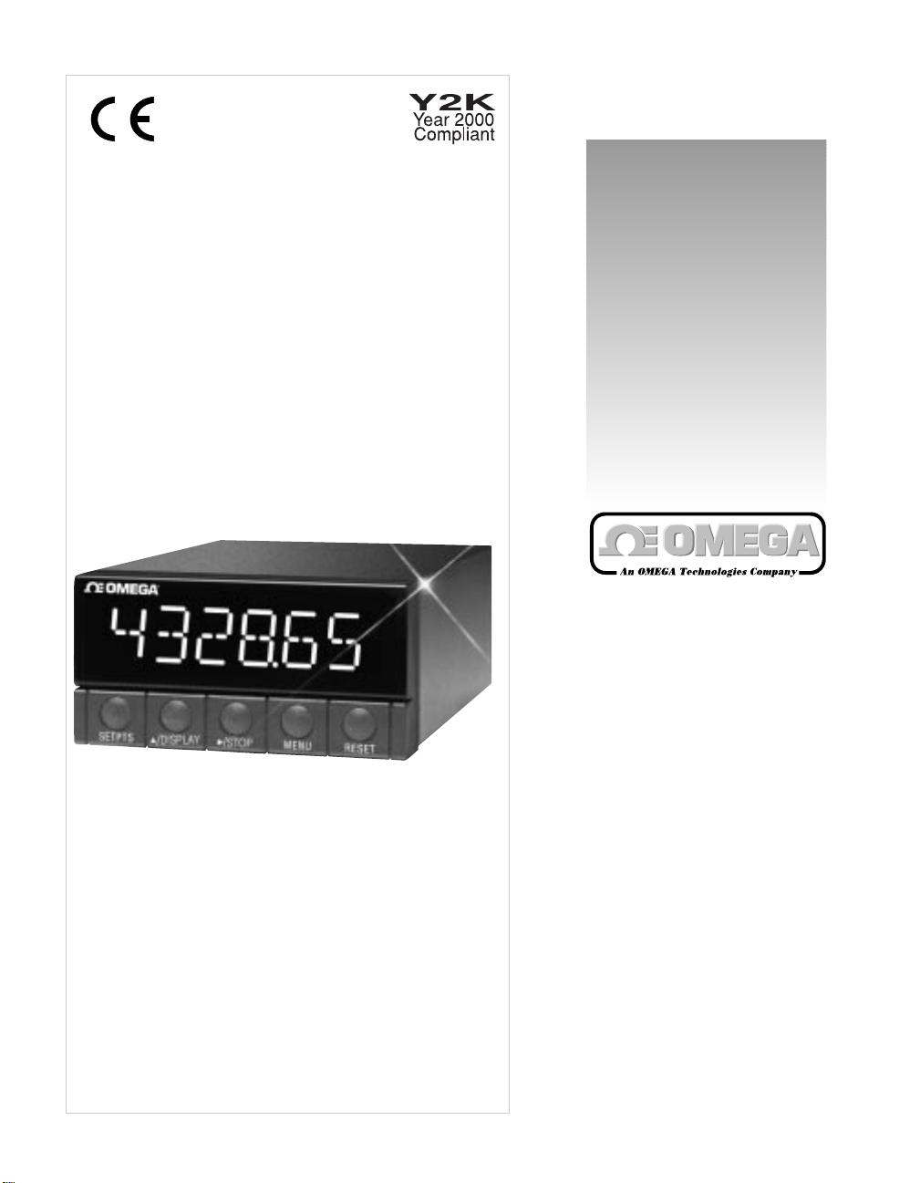
1 Basic meter with
main board (and
optional boards if
ordered by number);
in plastic case with
sleeve, panel
gasket, two
thumbnuts
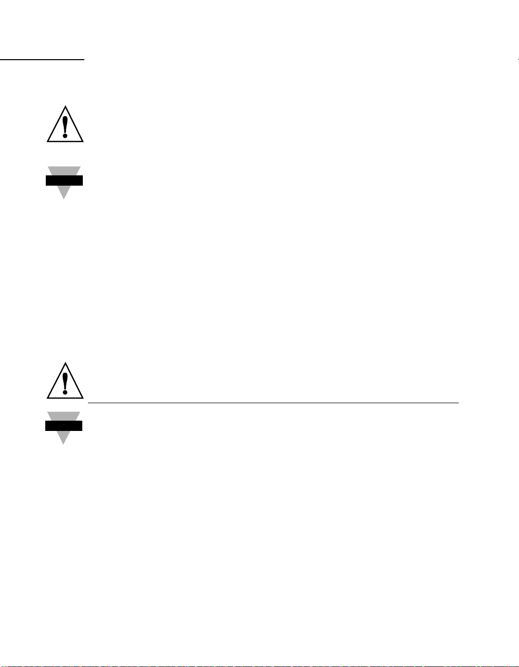
1 Front-panel
button cover available
with return of the
postcard (see meter box)
8
Page 17
QTY DESCRIPTION ILLUSTRATION
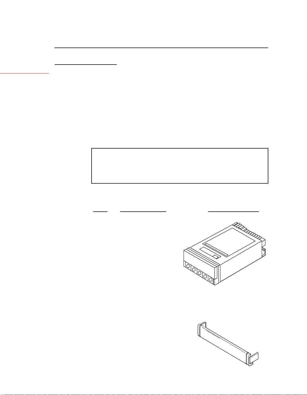
1 Orange, 3-socket
power connector (P1);
for AC input
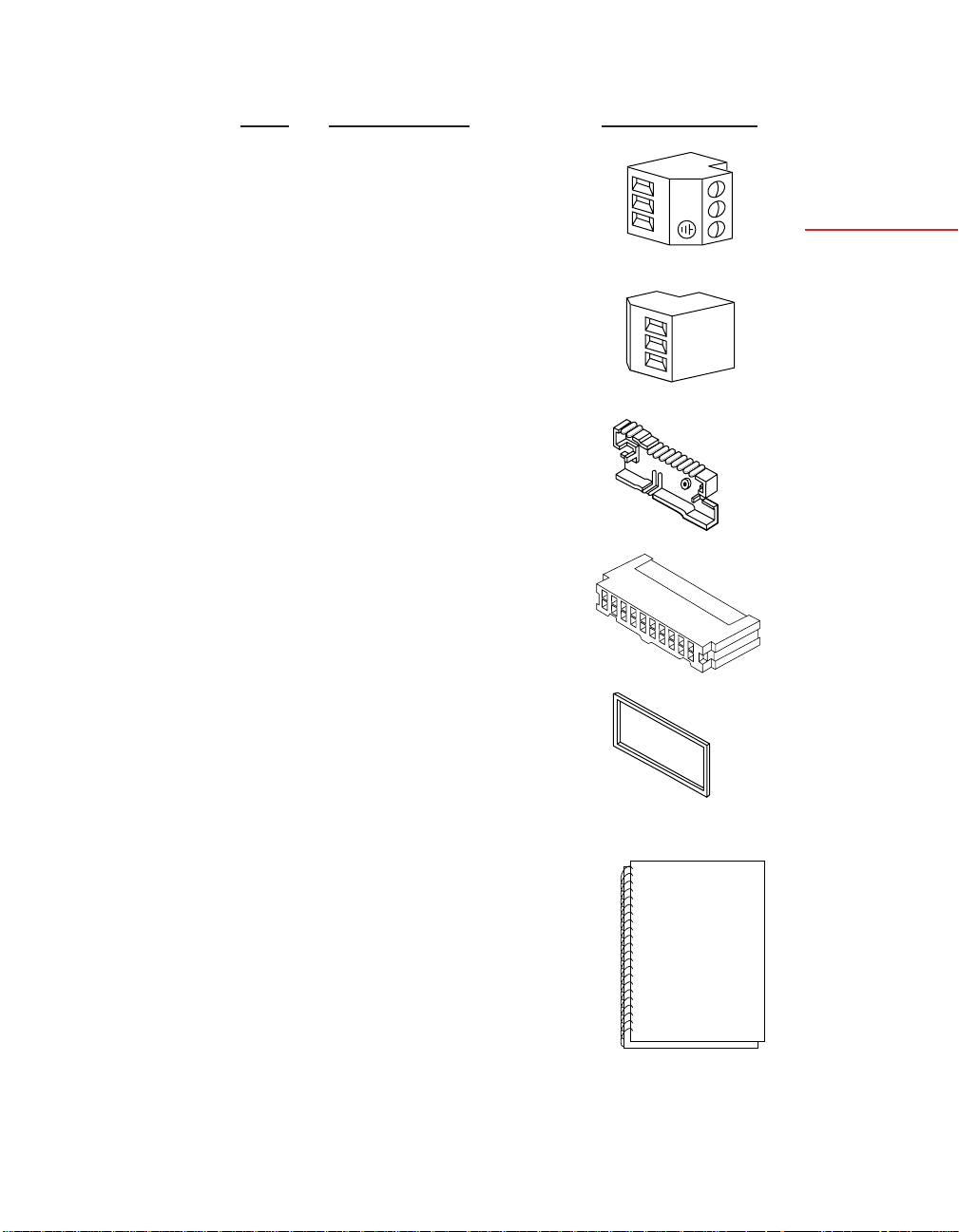
1 Gray, 3-socket
input connector (P3);
for signal input
1 Rear cover with
holddown screw
1 20-Socket Ribbon
Connector (P2)
L
2
1
2
N
3
1
2
3
Setup
2 Panel-mount gasket
(1 spare)
1 Operator’s manual
9
Page 18

2.2 SAFETY PRECAUTIONS
2
Setup
The meter is protected in accordance with Class I of EN61010.
Refer to Safety Considerations page.
WARNING: If your meter is to be wired to sensors or to control
!
2.2.1 POWER VOLTAGE
inputs that could have hazardous potentials, these potentials will be
carried to the 20-pin output connector (P2) at the rear. They will
also be present on the meter’s circuit boards. Follow all instructions
carefully, inserting the electronics into the case and installing connectors BEFORE connecting the meter to any source of power.
DO NOT contact any exposed metal parts, install optional board(s),
change jumpers, or in any way disassemble or assemble the meter
while it is connected to AC voltage.
Note the following information and guidelines for safe operation of
your meter:
Your power source voltage rating should agree with the voltage
under which the meter has been configured to operate. The first
thing you should do is verify this.
The meter’s operating voltage is shown in the VOLTS: entry of
the ID and Serial Number Label. Figure 2-1 shows a copy of this
label. It is located on the meter packing box and is clearly visible.
(Another label is also affixed to the meter case.)
MODEL:
SERIAL NO.:
PART NO.:
VOLTS: WATTS:
Figure 2-1. ID and Serial Number Label showing the Meter's
operating voltage.
10
Page 19

2.2.2 POWER WIRING
CAUTION: The meter has no power-on switch; it will be ON
!
when power is applied.
Section 2.3.5 shows you how to wire not only the AC power
connector, but all other connectors as well.
2.3 ASSEMBLY/DISASSEMBLY
2.3.1 OPENING THE METER
Your meter is fully assembled, but not wired. In most cases, if you
have ordered optional boards with the meter, these boards will
already be installed.
You will need to remove only the rear cover to complete wiring,
but you will have to open the meter to do one or more of the
following:
WARNING: You must disconnect and turn-off the power and
!
connector signals before accessing the unit and installing optional
boards. Failure to do so may result in injury!
2
Setup
a. Check or reconfigure the Transformer Jumpers on the Main
Board so that they correspond to your line voltage (W1 and W2
for 115 V ac, or W3 for 230 V ac). See Section 2.3.2.1.
b. Access jumpers on the Main and optional boards.
See Section 2.3.2.
c. Install optional boards. See Section 2.3.3.
11
Page 20
2
Setup
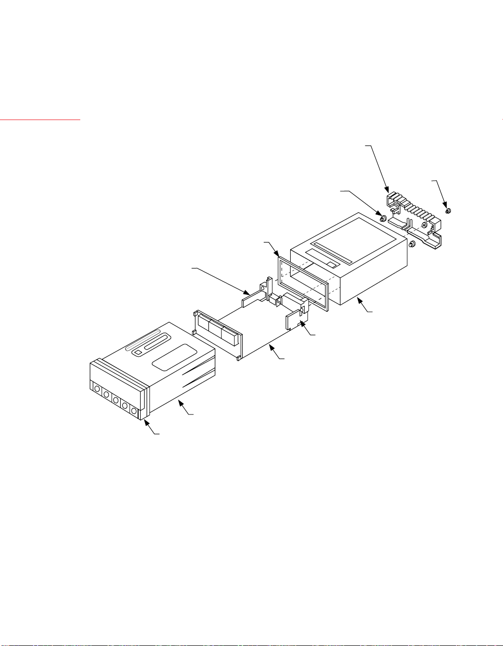
REAR
PROTECTIVE
COVER
COVER
MOUNTING
SCREW
THUMBNUTS
GASKET
SIGNAL
CONNECTOR
BOARD
SLEEVE
AC POWER BOARD
MAIN BOARD ASSY
CASE
BEZEL
Figure 2-2. Exploded View of the Meter
12
Page 21

Using Figures 2-2 as a guide, follow these simple instructions to
open the meter:
2
!
IMPORTANT: Turn-off the power and input signals from the
unit before proceeding. Failure to do so may result in injury!
1. Remove the cover mounting screw that secures the rear protective
cover to the meter, and remove the Rear Protective Cover.
If you are simply wiring the meter–but not checking jumpers or
installing or removing boards–this is as far as the meter needs to
be disassembled. Go to Section 2.3.5.
2. Remove all wiring connectors from the rear of the meter.
3. Remove the two thumbnuts that secure the case to the sleeve.
4. Remove the sleeve completely by sliding it back from the front
bezel.
Setup
13
Page 22

l. Introduction
1.1 DESCRIPTION
The Counter Timer is a multifunctional panel meter that can
measure counts, rates, flows, times, totals and batches from pulse
and analog input sources over the range of 0.2 to 20,000 Hz.
The meter can function in four different modes and be applied to a
wide range of applications, serving functions as simple as displaying
incoming pulses–or as complex as detecting out-of-limits
conditions, triggering alarms, and channeling communications for
a process control system.
The front panel displays values and messages with six, 14-segment
LEDs, indicates which mode-associated measurement is being
displayed through three Measurement LEDs, and indicates alarm
status through four Setpoint LEDs. Five buttons below the LED
display allow easy front-panel configuration and access to the
meter’s many features. These features can also be accessed through
digital communications.
1
Introduction
The meter can be mounted in a panel or simply placed on a bench top.
1.2 FEATURES
The following list outlines the meter’s features.
• Six-digit display
• Microprocessor-based, with nonvolatile memory-no battery
backup required
• Configurable via front-panel push buttons and/or through
RS-232 or RS-485 ports
• High accuracy
• Large digital offset enabling easy scaling in engineering units
• Five open-collector outputs for RATE, TOTAL, BATCH count,
BAT NO (Number of Batches), and TIME
• Programmable decimal point selection
• Read/Display/Output rates up to 25 per second
• Plug-in input and output optional boards
1
Page 23

1
1.3 METER MODES
Introduction
The meter can be configured to operate in four different modes.
These are Rate Meter/Totalizer (Rate), Rate Meter/Totalizer/
Square Root Extractor (Sq Rt), Batch Controller (Batch), and
Clock (C).
1.3.1 RATE METER/TOTALIZER
As a rate meter/totalizer, the meter measures the rate, totalizes and
displays pulses in any engineering units required, and provides
unregulated sensor excitation. The meter can also provide running
averages and process time in HH:MM:SS format in this mode.
With the addition of the Isolated Analog Input Board, analog signals
can be received and displayed in the required engineering units.
1.3.2 RATE METER/TOTALIZER/SQUARE ROOT EXTRACTOR
As a rate meter/totalizer/Square Root Extractor, the meter can
accept dc signals from any typical differential flow transmitter and
extract the square root to provide highly accurate flow values.
Digital calculation ensures accurate readings–which can be displayed in any engineering units desired.
This mode requires the Isolated Analog Input Board.
1.3.3 BATCH CONTROLLER
As a batch controller, the meter can count the batch, number of
batches completed, and the grand total of pulses received. In
addition, it has an internal timer for process time displayed in
HH:MM:SS format. Any of the above functions can be displayed
during the process without interrupting or stopping the process.
1.3.4 CLOCK
As a clock, the meter can function in real, 24-hour time mode
using the HH:MM:SS display format. It can also function as a
99-hour process timer. Time is derived from the power line
frequency, 50 or 60 Hz, which ensures accuracy. If power fails and
the meter is equipped with a backup battery, the clock function
continues working (although the display will not be lit). Refer to
Section 2.3.5.2 for information on battery backup.
2
Page 24

1.4 OPTIONAL BOARDS OVERVIEW
1
The meter is designed to accommodate numerous optional boards.
These boards transform the meter into a single instrument that
“can do it all.” On the input end, they allow the meter to accept
signals from a wider variety of sources, and on the output end, to
communicate with, or control a wide variety of other devices.
1.4.1 ISOLATED PULSE INPUT BOARD
The Isolated Pulse Input Board is a signal conditioning board that
allows the meter to accept low- and high-level input signals from
sources whose pulses may be too weak for the Main Board of the
meter to handle, or that need selectable hysteresis and/or regulated
excitation. This board is used mainly for weak magnetic pick-ups,
high-level line voltage sources, and NAMUR sources.
If this board is used, the Isolated Analog Input Board cannot be used.
(See Appendix B for specifications, jumper configuration, wiring,
and applications for the Isolated Pulse Input Board.)
1.4.2 ISOLATED ANALOG INPUT BOARD
Introduction
The Isolated Analog Input Board is a signal conditioning board
that converts analog signals to frequency and allows the meter to
accept input signals from non-pulsed or direct current sources. This
board is often used with differential pressure flow transmitters to
provide linear flow values. (First-time installation requires calibration using calibration data on the back of the board.)
If this board is used, the Isolated Pulse Input Board cannot be used.
(See Appendix C for specifications, jumper configuration, wiring,
and applications for the Isolated Analog Input Board.)
3
Page 25

1
Introduction
1.4.3 ISOLATED ANALOG OUTPUT BOARD
The Isolated Analog Output Board converts display readings into
voltage or current output. This board is often used as a control
board in process applications. (First-time installation requires
calibration using calibration data on the back-the solder or outboard side of the board.)
(See Appendix D for specifications, jumper configuration, wiring,
calibration, and applications for the Isolated Analog Output Board.)
1.4.4 ISOLATED PARALLEL BCD (BINARY-CODED DECIMAL) OUTPUT BOARD
The Isolated Parallel BCD Output Board produces binary-coded
decimal output for direct communication with a printer or with an
intelligent device such as a PLC (Programmable Logic Controller).
If this board is used, the Dual Relay Output Board cannot be used.
(See Appendix E for specifications, jumper configuration, wiring,
and applications for the Isolated Parallel BCD Output Board.)
1.4.5 DUAL RELAY OUTPUT AND 4 RELAY OUTPUT BOARD
The Dual Relay Output and 4 Relay Output Board enables
setpoint-triggered switching to an external device.
If either option board is used, the Isolated Parallel BCD Output
Board cannot be used.
(See Appendix F for specifications, jumper configuration, wiring,
and applications for the Relay Output Board.)
1.4.6 ISOLATED RS-232 SERIAL COMMUNICATIONS BOARD
The Isolated RS-232 Serial Communications Board provides an
isolated digital communications channel between a single meter
and a computer, serial printer, or other device.
If this board is used, the RS-485 Serial Communications Board
cannot be used.
(See Appendix G for specifications, jumper configuration, wiring,
and applications for the Isolated RS-232 Serial Communications
Board.)
4
Page 26

1.4.7 ISOLATED RS-485 SERIAL COMMUNICATIONS BOARD
The Isolated RS-485 Serial Communications Board provides an
isolated digital communications channel where multiple meters
(addressed from 0 to 199) can communicate with a single computer.
If this board is used, the RS-232 Serial Communications Board
cannot be used.
(See Appendix G for specifications, jumper configuration, wiring, and
applications for the Isolated RS-485 Serial Communications Board.)
1.5 AVAILABLE MODELS AND OPTIONS
The following models and options are available. Optional boards
are either installed at the time of purchase, or available as separate
items and installed by the user after purchase.
BASIC MODELS AND INPUT OPTIONS
MODEL
NUMBER DESCRIPTION
DPF401 No optional input board; Basic Meter accepts low
level and high level pulses from TTL/CMOS
sources, open collector outputs and contact closures;
provides 14-20 V unregulated sensor excitation
1
Introduction
DPF402 Isolated Pulse Input Board. Single-input for magnetic
pick-ups with low- and high-level signals; direct
connection to NPN, PNP, or NAMUR sensors.
Includes electrically floating, regulated sensor excitation rated 12.6 V @ 70 mA or 8.2 V or 5 V
DPF403 Isolated Analog Input Board. Input ranges of
0-1 mA, 4-20 mA, 0-5 V, 1-5 V, and 0-10 V are
jumper selectable. Standard factory default
calibration: 4-20 mA dc = 0-10000
FOR OPTIONS ADD SUFFIX TO MODEL NUMBER
-GR Green LED display
-230V 230 V ac, power
5
Page 27

1
Introduction
CONTROL/BCD OUTPUT OPTIONS
MODEL
NUMBER DESCRIPTION
DP40-B Isolated Parallel BCD (Binary-Coded Decimal)
Output Board
DP40-R Dual Relay Output Board; Two 7-amp,
Form-C Relays
DP40-R4 4 Relay Output Board; Two 7-amp & two 1 amp
Form-C Relays.
NOTE: Choose only one Control/BCD output option per meter.
A 40-socket plug is included with the BCD option.
ANALOG OUTPUT OPTIONS
MODEL
NUMBER DESCRIPTION
DP40-A Isolated Analog Output Board: Configurable output;
0-20 mA, 4-20 mA, 0-5 V, 0-10 V. Standard factory
default calibration: 0-10000 = 4-20 mA dc
DATA COMMUNICATIONS OPTIONS
MODEL
NUMBER DESCRIPTION
DPF400-S2 Isolated RS-232 Serial Communications Board*
DPF400-S4 Isolated RS-485 Serial Communications Board**
NOTE: Choose only one option per meter. Both computer
communications come with a 6-foot communications cable with
phone plug termination.
* We recommend purchase of 9SC2 or 25SC2 (see OPTIONS
below)
** We recommend purchase of 9SC4 or 25SC4 (see OPTIONS
below)
6
Page 28

OPTIONS
MODEL
NUMBER DESCRIPTION
DP40-9SC2 9-pin Serial Connector for RS-232 port
DP40-9SC4 9-pin Serial Connector for RS-485 port
DP40-25SC2 25-pin Serial Connector for RS-232 port
DP40-25SC4 25-pin Serial Connector for RS-485 port
1
Introduction
7
Page 29
2
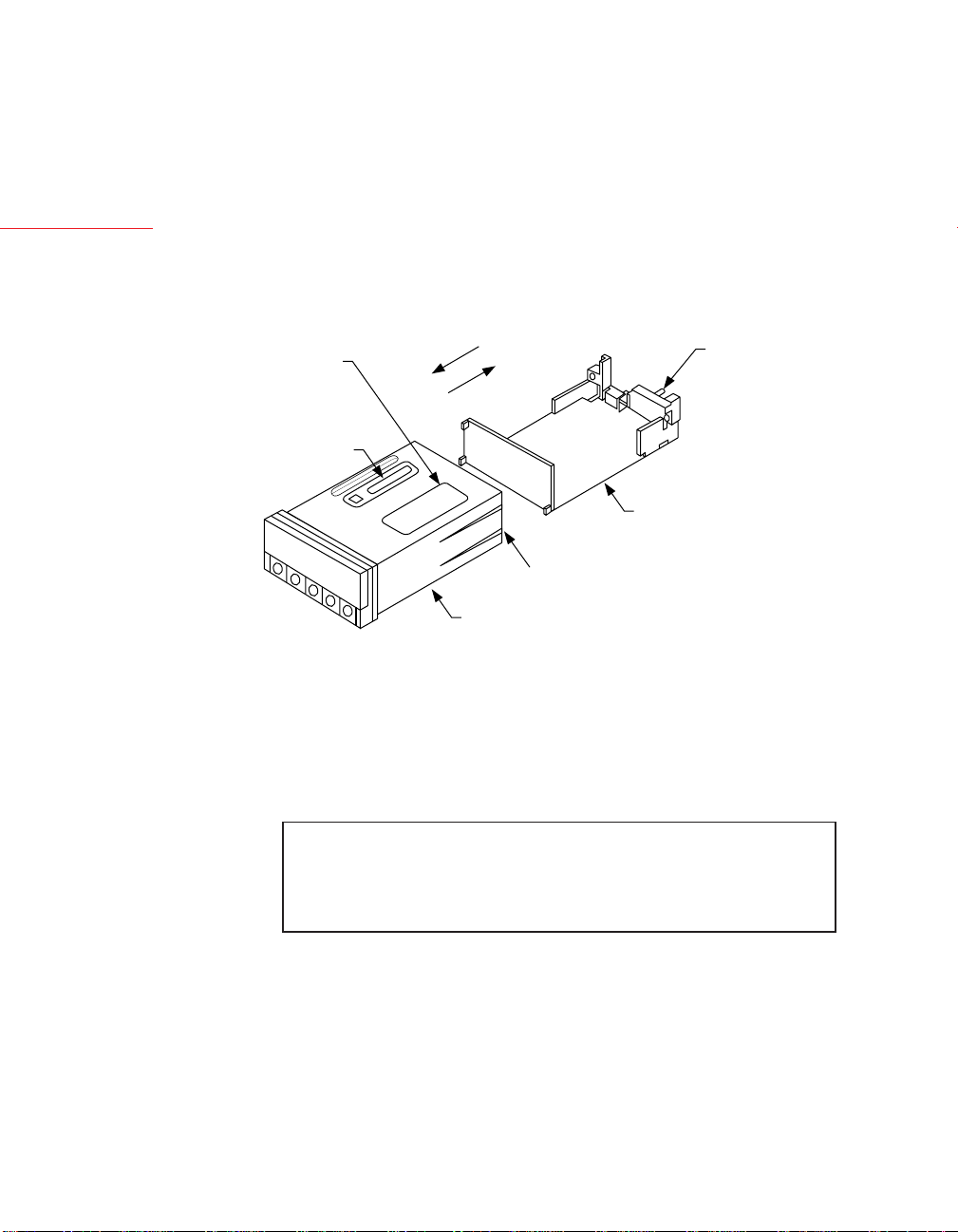
6. Using Figure 2-4 as a guide, bend the side-panel detents on the
case outward and pull the board assembly out of the case by the
mounting screw stem.
Setup
These six steps are known as “accessing the Main Board assembly.”
ID AND SERIAL
NUMBER LABEL
SIGNAL INPUT
JUMPER LABEL
Figure 2-4. Removing the Main Board Assembly from the Case
TO INSTALL
TO REMOVE
BEND DETENTS OUTWARD
TO INSTALL MAIN BOARD
CASE
MOUNTING
SCREW
STEM
MAIN BOARD ASSY
The meter is now disassembled to the point where you can check
and configure jumpers and install boards.
NOTE: When the sleeve is removed from the case in Step 5
above, the Connector Label on the case will be exposed.
See Figure 2-5. Use this label for reference when wiring or connecting plugs.
14
Page 30
P2/CABLE CONNECTOR
ALARM 1 OUTPUT
ALARM 3 OUTPUT
ALARM, BATTERY RETURN
P4/RS-232
6
5
4
3
2
1
P1/AC PWR
1
2
3
TWICE LINE FREQ
1 1
N/C
COMM RTN
RX
TX
RTS
N/C
{
LINE
NEUTRAL
AC GND
RESET-A
RESET-B
TEST TX
PULSE OUTPUT
RESET-C
STOP
P4/RS-485
6
5
4
3
2
1
P6/RELAY
1
2
3
1
3
5
7
9
10
11
12
13
14
15
16
17
18
19
20
N/C
B RX
A RX
COMM RTN
B TX/RX
A TX/RX
NO1
CM1
NC1
ALARM V + INPUT
2
ALARM 2 OUTPUT
4
ALARM 4 OUTPUT
6
ALARM 5 OUTPUT
8
DEBOUNCE
TEST RX
DIGITAL RETURN
HOLD / PRINT REQ
GATE INPUT
BACKUP BATTERY +
P5 ANALOG OUT
P7/RELAY
1
2
3
1
2
3
1
2
Setup
1
RETURN
4-20 mA
0-10 V
NO2
CM2
NC2
BCD
P5
1
.
.
.
P18 for 4 RELAY
1
P8
...
...
1
P6
P2
1
.
..........
.
..........
P1
.
1
1
CONNECT TO LOW VOLTAGE LIMITED ENERGY CIRCUITRY ONLY.
P8
1
P7
P4
.
.
.
.
1
.
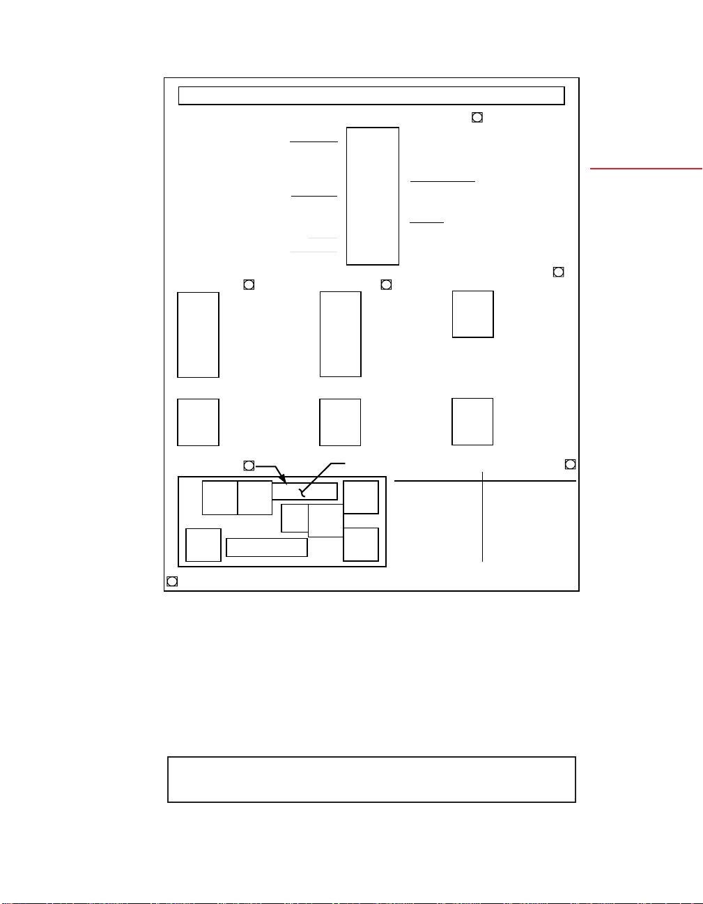
19
Figure 2-5. Connector Label
2.3.2 CHECKING AND INSTALLING JUMPERS
This section contains figures and instructions for checking and
installing jumpers, but it gives full information on the Main Board
only. If you have any optional boards, refer to the appropriate
appendix for specific jumper information.
NOTE: When referring to jumpers and the corresponding boards,
the view is from the REAR of the meter.
P9
P3
.
1
.
.
.
1
.
.
PULSE INPUT
P9 & P3
FILTER
SIG IN HI LEVEL
PULL UP/DOWN
EXCITATION
SIG IN LO LEVEL
SIG RETURN
ANALOG INPUT
+24 V EXC
SIGNAL IN
RETURN
TEST
TEST
TEST
1
15
Page 31
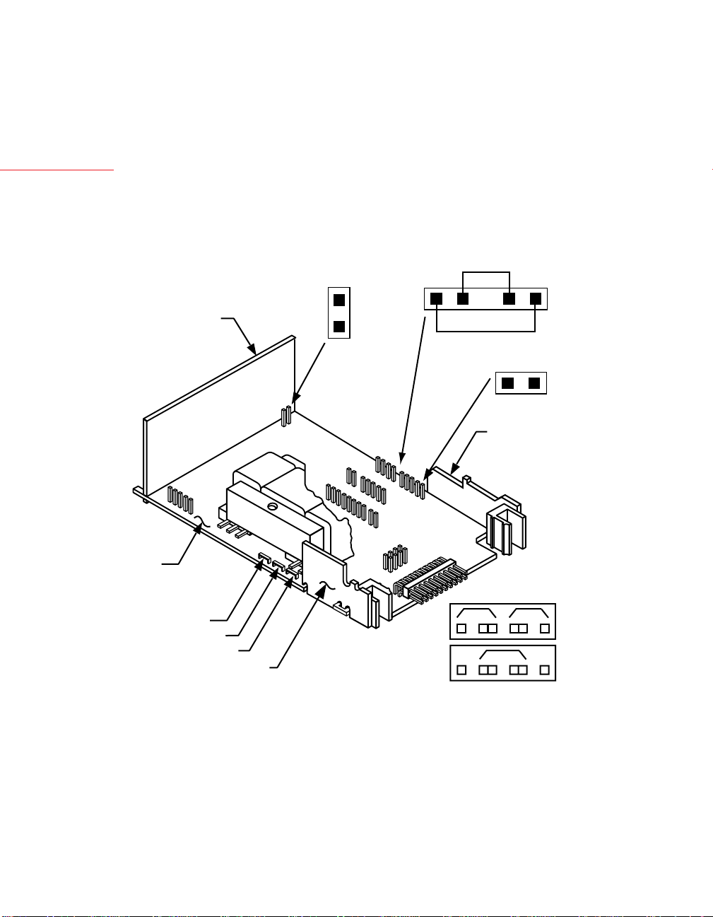
2.3.2.1 MAIN BOARD JUMPERS
2
Setup
DISPLAY
BOARD
MAIN
BOARD
!
Using Figure 2-6 and Table 2-1, configure or check Main Board
jumpers.
CAUTION: The meter has no power-on switch; it will be in
operation as soon as you apply power. To change the factory preset
jumpers, disconnect the power from the unit. Failure to do so may
result in injury! The jumpers must be changed by specially trained
personnel.
W6
(BEHIND
J13 PINS)
W7
S2
A
SIGNAL
CONNECTOR
BOARD
J3
J2
J14
T1
S1
J12
A
J13
J11
J10
W2
W3
W1
AC POWER BD
Figure 2-6. Main Board Jumpers
16
J1
W2 W1
W3
115 V ac
230 V ac
Page 32

TABLE 2-1. MAIN BOARD JUMPERS
LOCATION, VIEWING
THE BOARD FROM THE
JUMPER REAR OF THE METER FUNCTION
S1-A On the right, immediately Enables push buttons to
behind the Display board control lockout
programming
S2-A First two pins of J13 on Channels non-isolated
the right side of the Main excitation out to P3-1;
Board remove if input board used
W1 and
W2 Left side Enables 115 V operation
W3 Left side Enables 230 V operation
W6 and
W7 Right side of Main Board Bypasses isolation circuitry
next to J13 used for option boards;
remove if input board used
If your line voltage is 115 V ac, jumpers W1 and W2 (but NOT
W3) should be installed.
2
Setup
If your line voltage is 230 V ac, jumper W3 (but NOT W1 or W2)
should be installed.
NOTE: When referring to jumpers, the letter S means “switch”
and the letter W means “wire.” Switch jumpers are caps that bridge
two pins; they can easily be moved from one position to another.
Wire jumpers are soldered in; they must be cut when “removed”
and resoldered if reinstalled.
If no optional input board is used, jumper S2-A should be installed
on the first two pins of J13. This jumper brings non-isolated
excitation out to the P3-1 connection. Wire jumpers W6 and W7
should also be in place. These jumpers bypass the isolation circuitry
used for optional boards. See Figure 2-6.
17
Page 33

2
If one of the optional input boards is used, S2-A should be removed
(or be installed on only one pin), and W6 and W7 should be
removed.
Setup
S1-A allows front-panel control of the three lockouts so that you
can lock and unlock meter features. You may want to remove this
jumper later to lock in certain settings that you don’t want to be
changed. (See Section 5.3.) It should be installed when the meter
is first configured.
2.3.2.2 OPTIONAL INPUT AND OUTPUT BOARD JUMPER INFORMATION
JUMPER(S) CONFIGURING
BOARD TYPE PRESENT INFORMATION NOTES
Isolated pulse input Yes Appendix B –
Isolated analog input Yes Appendix C A one-time
calibration is
needed when
installed the
first time.
Isolated analog output No Appendix D A one-time
calibration is
needed when
installed the
first time.
Isolated Parallel
BCD output Yes Appendix E –
Dual relay output Yes Appendix F –
and 4 Relay output
Isolated RS-232 Serial
Communications
Output No Appendix G –
Isolated RS-485 Serial
Communications
Output Yes Appendix G –
18
Page 34

2.3.3 INSTALLING OPTIONAL BOARDS
FRONT
MAIN
BOARD
NOTE: When referring to installing optional boards, the view is
from the REAR of the meter.
Figure 2-7 shows the Main Board and Figure 2-8 shows an exploded
view of the meter with the optional board locations. In Figure 2-7,
the “front” of the board refers to the side with the Display Board;
the back is the side with J1 and J2 connections. Refer to Figures 2-7
and 2-8 as you insert optional boards. All boards must be jumpered
before insertion. See Section 2.3.2.
DISPLAY
BOARD
SIGNAL
CONNECTOR
BOARD
J2
J14
T1
J12
J11
J13
J10
2
Setup
J3
AC POWER BD
Figure 2-7. Main Board
REAR
J1
19
Page 35

2
Setup
PULSE
INPUT BOARD
OR ANALOG
INPUT BOARD
ISOLATED ANALOG
OUTPUT BOARD
RS-232/RS-485 BOARD
SIGNAL CONNECTOR
BOARD
P13
P20
P14
P12
P11
J13
J12 J11
J14
P10 (4 RELAY BOARD ONLY)
J20
BCD or 4 RELAY BOARD
INTERCONNECT BOARD
(PART OF BCD ASSY)
RETAINER (ALWAYS USED
EXCEPT FOR BCD OR
4 RELAY OPTION)
REAR
PROTECTIVE
COVER
DUAL
RELAY BOARD
P10
J10
AC POWER BOARD
MAIN BOARD ASSY
GASKET
COVER
MOUNTING
SCREW
THUMBNUTS
SLEEVE
BEND DETENTS OUTWARD
TO INSTALL MAIN BOARD
CASE
Figure 2-8. Exploded View of Main and Optional Boards
20
Page 36
2.3.3.1 ISOLATED PULSE INPUT BOARD
The Isolated Pulse Input Board plugs into J13 on the right side of
the Main Board. J13 consists 10-pins with a gap at pin 5.
S1
E
A
B
C
Figure 2-9. Isolated Pulse Input Board
D
F
J9
S1
P13
PIN 1
2
Setup
Follow these steps before installing the board:
1. Remove (or connect to a single pin) jumper S2-A, the black
jumper clip on the first two pins of J13 on the Main Board.
2. Remove wire jumpers W6 and W7, the two soldered-in connections to the immediate right of J13.
3. Plug the input board onto the J13 jack.
The Pulse Input Board and Analog Input Board can be installed
at J13. However, only one can be installed at a time.
Refer to Appendix B to configure this board.
21
Page 37
2.3.3.2 ISOLATED ANALOG INPUT BOARD
2
Setup
The solder side of the Isolated Analog Input Board contains
calibration data for precisely calibrating the board. Make sure you
copy the data before you install the board.
Record them here:
Input 1 @ 4 mA =
Input 2 @ 20 mA =
Input 1 @ 0 V =
Input 2 @ 5 V =
The Isolated Analog Input Board plugs into J13 also. See section
2.3.3.1, Steps 1 through 3.
A
AB
C
C
B
E
D
S1
J9
S2
S2
Figure 2-10. Isolated Analog Input Board
The Analog Input Board and Pulse Input Board can be installed
at J13. However, only one can be installed at a time.
Refer to Appendix C to configure this board.
P13
PIN 1
22
Page 38

2.3.3.3 ISOLATED ANALOG OUTPUT BOARD
The solder side of the Analog Output Board contains calibration
data for precisely calibrating the board. Make sure you copy the
data readings–CAL VZ (Calibrate Voltage Zero), CAL VS (Calibrate Voltage Span), CALmAZ (Calibrate milliAmp Zero), and
CALmAS (Calibrate milliAmp Span)–before you install the board.
Record them here:
CAL VZ =
CAL VS =
CALmAZ =
CALmAS =
The Analog Output Board plugs into J12, between J13 (on the
right edge of the Main Board) and the transformer. J12 consists of
8 pins with a gap at pin 6.
NOTE: Future analog output boards will be supplied with a 10-pin
connector for use with a DC powered version of this instrument.
CALmAS
2
Setup
CALmAZ
CAL VS
CAL VZ
130 m
S=
PIN 1
Figure 2-11. Isolated Analog Output Board
Refer to Appendix D to configure this board.
723
V Z=
P5
23
mA
Z=
715
12125
S=
P12
PIN 1
Page 39
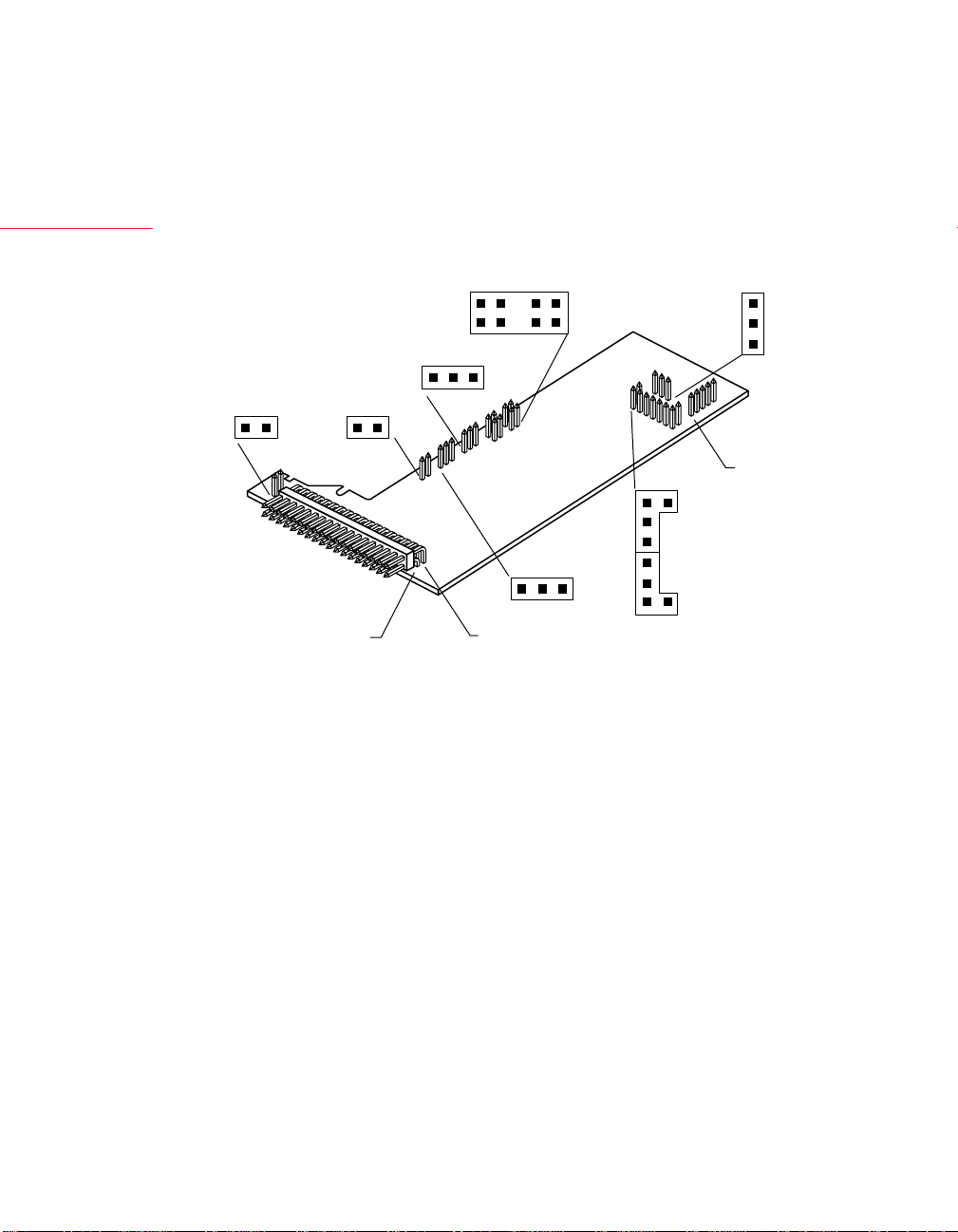
2.3.3.4 ISOLATED PARALLEL BCD (BINARY-CODED DECIMAL) OUTPUT BOARD
2
Setup
The Isolated Parallel BCD Output Board mounts above (and
parallel to) the Main Board using the small vertical Interconnector
Board as a support. Note that this board is inserted component-
side down.
S5
A
E
C
G
S4
A B
S1
A A
J8
U1
S2
L1
S3
A B
S6
B
A
A
S7
B
A
B
S8
J20
PIN 1
Figure 2-12. Isolated Parallel BCD Output Board
1. Insert the P14 plug of the Interconnect Board onto the J14 pins
on the Main Board. J14 consists of 5 vertical pins on the left side
of the Main Board, immediately behind the Display Board.
2. Insert the P20 connector of the Interconnect Board onto the J20
pins on the BCD Board. (See Figure 2-8.)
The Dual Relay or 4 Relay Output Option may not be installed
at the same time as the Parallel BCD Output Option.
Refer to Appendix E to configure this board.
24
Page 40

2.3.3.5 DUAL RELAY AND 4 RELAY OUTPUT BOARDS
4 RELAY BOARD
PIN 1 OF CABLE
PIN 1
MAIN BOARD
J10
P10
The Dual Relay Board is a vertical board and the 4 Relay board is a
horizontal board which plugs into J10, the double row of 4 pins
each at the rear of the Main Board.
P7
P6
Figure 2-13. The Dual Relay Output Board and the 4 Relay
Output Board.
Both the Dual Relay Output Board and the 4 Relay Output
Board can be installed at J10. However, only one option board can
be installed at a time.
Refer to Appendix F to configure this board.
2
Setup
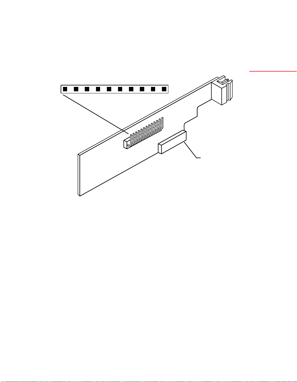
2.3.3.6 ISOLATED RS-232 SERIAL COMMUNICATIONS BOARD
The Isolated RS-232 Serial Communications Board plugs into J11,
to the right of the transformer.
P 11
Figure 2-14. Isolated RS-232 Serial Communications Board
J11 consists 11 pins with a gap at pin 9. (Note that the mating
socket of the communications board does not mate with pin 11
of J11; this pin is reserved for future use.)
The RS485 Board can be installed at J11. However, only one
option board can be installed at the same time.
25
J4
PIN 1
Page 41

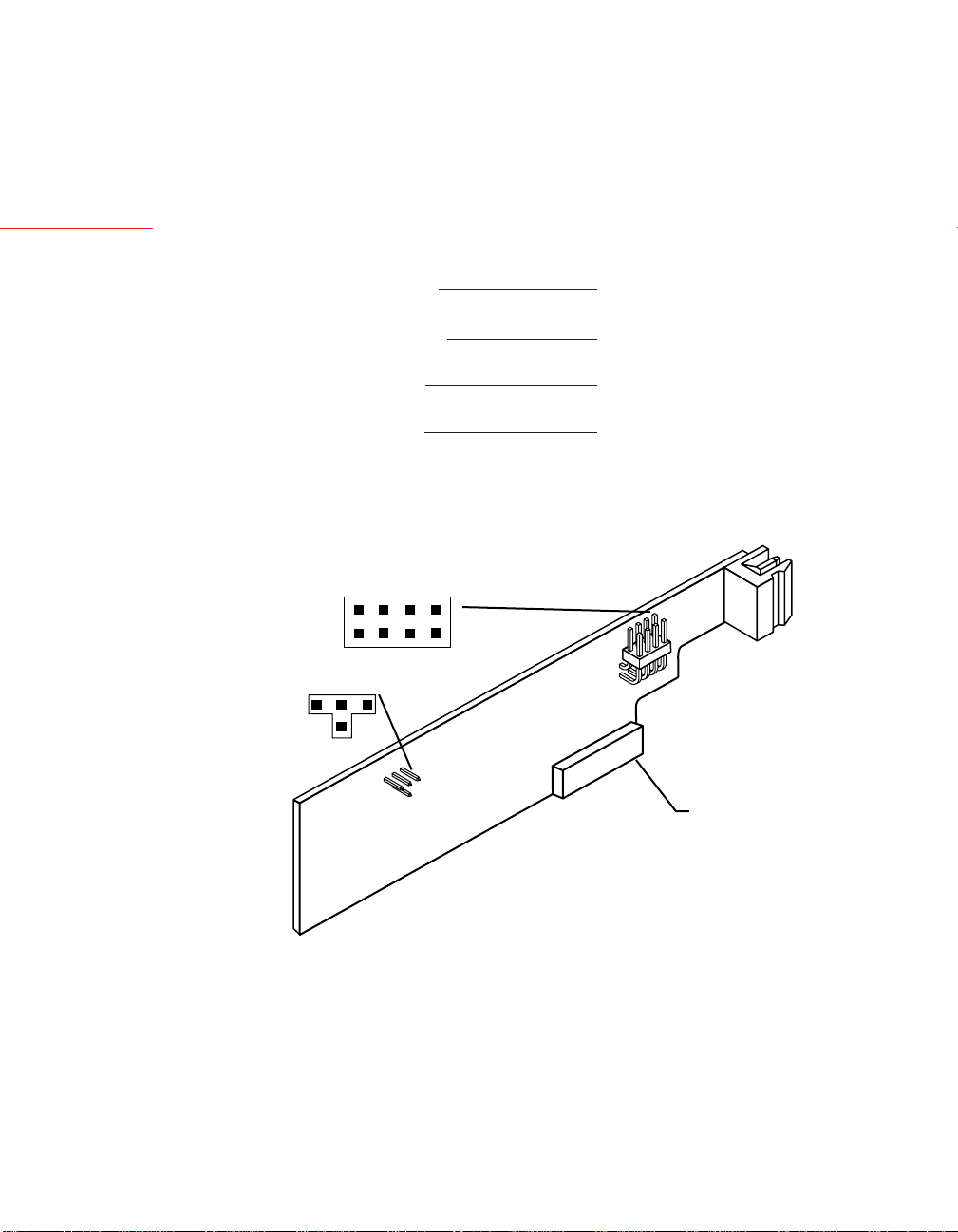
2.3.3.7 ISOLATED RS-485 SERIAL COMMUNICATIONS BOARD
2
Setup
The Isolated RS-485 Serial Communications Board mounts in a
manner identical to that of the RS-232 board in the previous
section.
S1
A
B
Figure 2-15. Isolated RS-485 Serial Communications Board
The RS232 Board can be installed at J11. However, only one
option board can be installed at the same time.
Refer to Appendix G to configure this board.
2.3.4 REINSERTING THE MAIN BOARD ASSEMBLY INTO THE CASE
S3
A
P11
J4
PIN 1
A
S2
2.3.5 WIRING
Reinsert the Main Board into the case once Main Board jumpers
have been configured (Section 2.3.2.1) and optional boards have
been configured and installed (Sections 2.3.2.2 through 2.3.3).
Spread the side-panel detents of the case, and carefully slide the
Main Board all the way in.
You are now ready to wire your meter.
The way you connect your input wiring to your meter depends on
your pulse or input source, and the types of optional boards you
have installed. Therefore, this section contains complete instructions for wiring only the AC Power connector (P1), and guidelines
for wiring the input/output control connector (P2). You will be
referred to the appropriate appendix for specific wiring instructions
based on your optional board configuration.
26
Page 42

2.3.5.1 P1 - AC POWER WIRING
!
!
CAUTION: As mentioned in Section 2.2.2, the meter has no
power ON/OFF switch. The meter will be ON when power is
applied.
WARNING: Do not connect ac power to your meter until you
have completed all input and output connections. Failure to do
so may result in injury! This device must only be installed
electrically by specially trained electrician with corresponding
qualifications. The meter is factory set to the power specified by
the customer at the time of ordering. The voltage is printed on
the Label under Input power.
Wire your power (from a wall socket or other source) to P1, the
orange, 3-socket connector that plugs into the 3 pins on the left
side as you view the meter from the rear. Refer to Figure 2-16 and
Table 2-2 below.
LN
ORANGE
CONNECTOR
EARTH
NEUTRAL
LINE
FUSE
SWITCH
Check for proper Earth grounding in the
power distribution system (single phase).
GREEN WIRE
L
N
[
P1
1
2
3
2
Setup
Figure 2-16. P1, ~AC Power Connector Wiring
TABLE 2-2. P1, AC POWER CONNECTOR WIRING
P1 AC POWER EUROPE USA
1 {ac Line Brown Black
2 {ac Neutral Blue White
3 {ac Protective Earth GND Green/Yellow Green
2.3.5.2 BATTERY BACKUP CONNECTIONS
The purpose of the battery backup is to allow the internal clock to
continue to run when a loss of the AC power is experienced. All
other functions will cease to operate until AC power is resumed. The
minimum requirements of the battery needed is 7-12 Vdc at 50 mA.
Connect the negative lead of your battery to P2-9 (ALARM,
BATTERY RETURN) and the positive lead of your battery to
P2-20 (BACKUP BATTERY).
WIRE COLOR
27
Page 43

2.3.5.3 P2 - CONTROL INPUT/OUTPUT WIRING
2
Setup
P2, the 20-socket ribbon connector plugs into the center rear of the
Main Board, sends out the setpoint transistor collectors and permits
remote control of significant meter features. Table 2-3 describes
the function of each pin.
TABLE 2-3. P2, INPUT/OUTPUT CONNECTIONS
P2
SOCKET/
PIN NO. DESCRIPTION/FUNCTION
P2-1 Setpoint 1 transistor open-collector output
P2-2 Input of external V+ used for setpoint transistors so that
internal diodes can clamp inductive-load spikes
P2-3 RESET-A: When grounded in Rate or Sq Rt Modes,
resets TOTAL to 0, resets TOTAL setpoint latches; in
Batch Mode, starts a new BATCH count, increments
BAT NO (Number of Batches), resets BATCH-count
setpoint latches, and clears any STOP (See Section 4.10)
P2-4 Setpoint 2 transistor open-collector output
P2-5 Setpoint 3 transistor open-collector output
P2-6 Setpoint 4 transistor open-collector output
P2-7 Twice-line-frequency, 5-V pulse output (also used by
microcontroller to detect line failure)
P2-8 Setpoint 5 transistor open-collector output
P2-9 Return ground connection: SP-transistor external supply
and/or backup battery ground
P2-10 Debounce capacitor for P3-2 signal input (tie to ground
for contact input)
P2-11 RESET-B: When grounded in Rate or Sq Rt Modes,
starts a new AVG RTE (Average Rate) period, resets
RATE setpoint latches; in Batch Mode, resets BAT NO
(Number of Batches) to 0 (if count is up) or to
Setpoint 4 value (if count is down), and resets
BAT NO setpoint latches (if SP4 has been assigned)
(See Section 4.10)
P2-12 TTL-level Test RX
P2-13 TTL-level Test TX
P2-14 Meter digital ground (internally connected to P2-9)
P2-15 Programmable Pulse Output (see AL TI, Section 5.4.12)
28
continued next page
Page 44

continued from previous page
P2
SOCKET/
PIN NO. DESCRIPTION/FUNCTION
2
P2-16 HOLD/PRINT REQUEST: When grounded, if enabled
by CF4.3 and CF4.4, freezes displayed value/initiates
print out (V01 Command)
P2-17 STOP: When grounded in rate or sq rt modes, stops
the clock until released; in batch mode, sets all setpoint
outputs to their active states
P2-18 GATE: Nonisolated input: Can be used as the input
signal or to gate P3/P9 inputs
P2-19 RESET-C: when grounded in rate or sq rt modes,
resets the clock to SET TI (Set Time, see Section
5.4.15), and resets TIME setpoint latches; in Batch,
resets the clock to SET TI, resets the grand TOTAL to
0, resets a TOTAL setpoint latch (See Section 4.10)
P2-20 Backup battery +V input
2.3.5.4 BASIC METER INPUT WIRING
If you are going to be operating the meter as a basic meter–with no
optional boards–see Appendix A for further wiring instructions.
2.3.5.5 ISOLATED PULSE INPUT BOARD WIRING
If your meter has the isolated pulse input board, see Appendix B for
wiring.
Setup
2.3.5.6 ISOLATED ANALOG INPUT BOARD WIRING
If your meter has the isolated analog input board, see Appendix C
for wiring.
2.3.5.7 ISOLATED ANALOG OUTPUT BOARD WIRING
If your meter has the isolated analog output board, see Appendix D
for wiring.
2.3.5.8 ISOLATED PARALLEL BCD OUTPUT BOARD WIRING
If your meter has the isolated parallel BCD output board, see
Appendix E for wiring.
29
Page 45

2.3.5.9 DUAL RELAY OUTPUT AND 4 RELAY OUTPUT BOARD WIRING
2
Setup
If your meter has the Dual Relay Output Board or the 4 Relay
Output Board, see Appendix F for wiring.
2.3.5.10 ISOLATED RS-232 OR RS-485 SERIAL COMMUNICATIONS BOARD WIRING
If your meter has either the Isolated RS-232 or RS-485 Serial
Communications Board, see Appendix G for wiring or connections.
2.4 PANEL-MOUNT ASSEMBLY
The meter can be mounted in a panel so that the front of the meter
is flush with the vertical panel surface. Panel mounting can be
seen as simply “sandwiching” the panel between the inner case and
the outer sleeve in the last phases of assembly. Figure 2-17 shows
the panel cutout dimensions, and the dimensions for the panel
thickness. It requires that the following already be done:
1. Your line voltage rating has been checked against the meter
rating on the ID and serial number label on the meter case. See
Section 2.2.1.
2. You have configured all jumpers–those on the main board as well
as those on any optional boards. See Section 2.3.2.1 for main
board jumper configuration and Appendices B through G for
optional board jumper configuration.
!
3. You have installed all optional boards and inserted the main
board assembly back into the case. See Sections 2.3.3 and 2.3.4.
4. You have wired P1, the AC power connector, and P2 the input/
output control connector; connectors are not installed in the
meter, but are ready to be. See Sections 2.3.5.1 and 2.3.5.2.
5. You have wired all connectors for optional boards; connectors
are not connected to the meter, but are ready to be. See Appendices B through G.
CAUTION: Connectors with the wiring connections will be
installed after mounting the unit.
If all of these steps are done, continue here using Figure 2-17 as a
guide:
30
Page 46

2
PANEL CUTOUT
0.06
R
[1.5]
4PLCS
3.622 +0.032/-.000
[92.00 +0.81/-0.00]
PANEL
Setup
PANEL THICKNESS
0.25 [6.4] MAX
0.03 [0.8] MIN
1.772 +0.024/-.000
[45.00 +0.61/-0.00]
REAR
PROTECTIVE
COVER
COVER
MOUNTING
SCREW
THUMBNUTS
METER
SLEEVE
CASE
GASKET
BEZEL
Figure 2-17. Panel-Mount Assembly
31
Page 47

2
6. Punch or cut a hole in the panel using the panel cutout
dimensions in Figure 2-17. Remove burrs and paint the panel
as required.
Setup
!
7. Insert the panel-mount gasket around the rear of the case and
slide it forward to the bezel (if it’s not already in place).
8. Working from the front of the panel, insert the case assembly,
rear end first, all the way into the panel cutout such that the
gasket firmly backs the panel surface.
9. Working from the rear of the panel, slide the sleeve forward
over the case and up to the panel surface.
The panel should now be sandwiched between the bezel-backed
gasket in front and the sleeve in back.
10. Replace the thumbnuts that secure the sleeve tabs to the case.
WARNING: Do not "turn-on" the ac power and input signals
until all connections are connected to the meter.
11. Set P1, the AC power connector, aside and connect or reconnect all other connectors to the back of the meter using Figures
3-2 and 3-3 in Section 3.2 as guides.
NOTE: The P1 connector is “keyed”; it is shaped in such a way
that it fits only the J1 male pins.
Connect P1 last.
12. Replace the rear protective cover and secure it with the cover
mounting screw.
Your meter is now ready for operation and you can turn-on the
power.
32
Page 48
3. Front and Rear Features
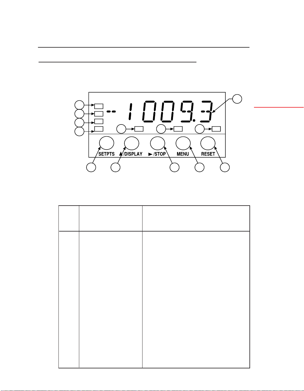
3.1 FRONT-PANEL DISPLAYS AND BUTTONS
Refer to Figure 3-1 as you read about front panel displays and
buttons.
2
2
2
3
4 5
Figure 3-1. Front Panel
TABLE 3-1. FRONT-PANEL DISPLAYS AND BUTTONS
FRONT-PANEL
BUTTON OR
ITEM FEATURE DESCRIPTION/FUNCTION
1 6-Digit Display 6-Digit, 14-segment, 0.54-inch LED
3
3 3
6
display produces alphanumeric readout;
programmable decimal point; red with
green option
7
8
3
Front
1
and Rear
Features
2 Measurement Green LEDs; designate which
measurement is being
displayed (See DISPLAY, below)
3 Setpoint LEDs Red LEDs; designate which setpoints are
active; when flashing, designate which
setpoint is being viewed and/or set
4 SETPTS Button In Run mode changes to Setpoint Mode
and allows setting of five setpoints; allows
value change by pressing the ▲/DISPLAY
button and the /STOP button
33
▲
continued next page
Page 49

3
Front
and Rear
Features
continued from previous page
FRONT-PANEL
BUTTON OR
ITEM FEATURE DESCRIPTION/FUNCTION
5 ▲ /DISPLAY Two-Function button: In Run Mode,
Button sequences the display through mode-
▲
6 /STOP Button Two-Function button: In run mode,
(STOP enabled imposes STOP condition; in configuraby CF4.8=1) tion and setpoint modes, accesses the
associated measurements; in Configuration and Setpoint Modes, sequences
through possible digit and numerical
settings
• In Rate-Run Mode, sequences the
display through unlocked values of
RATE, AVG RT, TOTAL, and TIME
• In Sq Rt-Run Mode, sequences the
display through unlocked values of
SQ RT, AVG RT, TOTAL and TIME
• In Batch-Run Mode, sequences the
display through unlocked values of
BATCH, BAT NO, TOTAL and TIME
• In Setpoint and Configuration Modes,
sequences through possible
alphanumeric settings: For
numbers,increments the flashing digit
by 1; for alphabetical settings,
sequences to the next possible setting
next digit or choice
• In batch-run mode, if CF4.8=1, puts
all setpoints in their ACTIVE states
and displays STOP. (After 3 seconds,
▲
the /STOP button can be pressed
again to reset alarms and return to run
mode)
• Inactive in rate-run or sq rt-run modes
• In setpoint mode advances the
flashing digit one place to the right,
making the new digit accessible for
resetting by the ▲/DISPLAY button
34
continued next page
Page 50

continued from previous page
FRONT-PANEL
BUTTON OR
ITEM FEATURE DESCRIPTION/FUNCTION
7 MENU Button • In run mode, terminates measure-
(Enabled by ments and switches to Configuration
L3C.8=0; Mode
disabled by • In configuration mode, stores new
L3C.8=1 and values in EEPROM (nonvolatile
removal of S1) memory) and advances the display to
8 RESET Button • In Run Mode, RESETs the value of
(Enabled by the measurement on display to zero
CF4.7=0) (or to the reset value designated by
• In configuration mode, advances the
flashing digit one place to the right,
making the new digit accessible for
resetting by the ▲/DISPLAY button;
advances the displayed choice to the
next choice in sequence
the next parameter to be programmed
configuration) Also RESETs any
latched alarms assigned to the dis
played measurement
• In setpoint mode, switches back to run
mode; any new setpoint values entered
with the /STOP button and the
▲/DISPLAY button that have not
been stored are discarded
• In configuration mode, the first press
backs up one parameter (Menu item);
the second one RESETs the meter and
returns to run mode
▲
3
Front
and Rear
Features
3.2 REAR CONNECTORS
Figure 3-2 shows the rear of the meter with the Dual Relay Board,
and a serial communications board. Figure 3-3 shows it with the
Isolated Parallel BCD Output Board, a serial communications
board, Isolated Analog Output Board, and Analog or Pulse Input
Board. Figure 3-4 shows the connector label with pin assignments.
35
Page 51

3
Front
and Rear
Features
P6
1
2
P1
L
1
2
N
3
P7
3
1
2
3
J4
1
P2
1
20
P18
2
3
4
5
6
1
2
3
1
2
3
P9
P3
Figure 3-2. Rear View of the Meter with the 4-Relay and
Serial Communications Boards
U1
L1
P1
L
1
2
N
3
1
P8
U20
L20
P5
1
2
3
1
2
3
P9
P3
J4
1
2
20
P2
3
Figure 3-3. Rear View with the BCD, Serial Communications, and
Analog Output Boards
36
Page 52

P2/CABLE CONNECTOR
ALARM 1 OUTPUT
ALARM 3 OUTPUT
1
2
3
{
1
P1
...
1
N/C
COMM RTN
RX
TX
RTS
N/C
LINE
NEUTRAL
AC GND
P8
P6
P2
..........
..........
1
TWICE LINE FREQ
...
1
ALARM, BATTERY RETURN
P4/RS-232
6
5
4
3
2
1
P1/AC PWR
.
.
.
1
CONNECT TO LOW VOLTAGE LIMITED ENERGY CIRCUITRY ONLY.
RESET-A
RESET-B
TEST TX
PULSE OUTPUT
RESET-C
1 1
1
P8
P4
.
.
.
.
1
.
19
P7
STOP
P4/RS-485
6
5
4
3
2
1
P6/RELAY
1
2
3
BCD
1
.
.
.
P5
1
3
5
7
9
11
13
15
17
19
P18 for 4 RELAY
.
1
.
.
P9
.
1
.
.
P3
ALARM V + INPUT
2
ALARM 2 OUTPUT
4
ALARM 4 OUTPUT
6
ALARM 5 OUTPUT
8
DEBOUNCE
10
TEST RX
12
DIGITAL RETURN
14
HOLD / PRINT REQ
16
GATE INPUT
18
BACKUP BATTERY +
20
N/C
B RX
A RX
COMM RTN
B TX/RX
A TX/RX
NO1
CM1
NC1
PULSE INPUT
FILTER
SIG IN HI LEVEL
PULL UP/DOWN
EXCITATION
SIG IN LO LEVEL
SIG RETURN
1
P5 ANALOG OUT
1
2
3
P7/RELAY
1
2
3
P9 & P3
ANALOG INPUT
+24 V EXC
SIGNAL IN
RETURN
TEST
TEST
TEST
3
Front
and Rear
Features
1
RETURN
4-20 mA
0-10 V
NO2
CM2
NC2
1
Figure 3-4. Connector Label
TABLE 3-2. REAR CONNECTORS
CONNECTOR
NUMBER DESCRIPTION
P1 AC Power Connector; 3-socket connector for AC power input.
P2 Control Input/Output connector; 20-socket ribbon
connector sends out setpoint transistor collectors and
allows remote control of certain meter features.
continued next page
37
Page 53

3
Front
and Rear
Features
continued from previous page
CONNECTOR
NUMBER DESCRIPTION
P3 Input and Excitation connector; 3-socket input plug for
unregulated excitation for Basic Meter; low level
input and excitation for Isolated Pulse Input Board.
Not used with Analog Input Board (test points for
factory use only).
P4 Isolated RS-232 or RS-485 Serial Communications
Board connection for digital communications;
6-spring RJ-12 telephone plug (for 7-foot cable
furnished with either board).
P5 Isolated Analog Output connector; 3-socket output plug
for optional analog output.
P6 and P7 Dual Relay and 4 Relay connector; 3-socket output
plugs for optional 7-amp, Form-C Relays.
P8 Isolated parallel BCD Output Board connector; 40-socket
plug for optional BCD output; connects to ribbon cable.
P9 3-Socket optional input board connector; for Isolated Pulse
Input Board, high-level input and filter connections;
for Isolated Analog Input Board, input, excitation,
and common return.
P18 4 Relay connector; 6-socket output plug for optional 1-amp,
Form-C relays.
38
Page 54

4. Basic Concepts and Approaches to
Setup and Configuration
Your application and what you need to accomplish will dictate setup
and configuration of the meter. This section shows you how the meter
works; it contains information that will help you see how your meter
can best be connected to peripheral devices, or to resets and alarms.
4
4.1 CHOOSING AN OPERATING MODE
One of the first decision you need to make is to determine what
MODE you want the meter to run in. There are two rate
modes—Rate and Sq Rt—that count per unit time, and one
counting mode—Batch.
If you need to measure a simple rate, you should use Rate Mode. If
your input signal is proportional to the square of the quantity that
you are measuring, you should use Sq Rt mode. Differential
pressure transducers produce this type of input and almost always
require the use of the isolated analog input board. If you need to
count, especially on numerous levels, you should use Batch Mode.
4.2 MODE-ASSOCIATED MEASUREMENTS
Each mode has 4 associated measurements that can be displayed by
pressing the ▲/DISPLAY button on the front panel. Table 4-1
shows these measurements for each mode.
TABLE 4-1. MODE-ASSOCIATED MEASUREMENTS
Basic
Concepts
MODE ASSOCIATED MEASUREMENT
Rate RATE AVG RT TOTAL TIME
Sq Rt SQ RT AVG RT TOTAL TIME
(Square Root) (Average Rate)
Batch BATCH BAT NO TOTAL TIME
(unit count) (Number of
Batches)
For instance, if the meter is in Rate Mode, you can press the
▲/DISPLAY button to sequence through display readings of
RATE, AVG RT (Average Rate), TOTAL, and TIME.
39
Page 55

4
When any mode-associated measurement (except TIME) is on the
display, the corresponding Measurement LED is lit. The first
measurement in any mode (RATE, SQ RT, or BATCH) corresponds to the top LED.
The factory preset operating mode of the meter is Rate. The
factory preset Rate units are Hertz–cycles per second–which the
meter interprets as pulses per second.
Basic
Concepts
4.3 USING SCALE FACTORS
One of the great features of the meter is that the input units can be
converted to units other than Hertz (frequency), and the associated
TOTAL can also have independent units. This is accomplished by
using scale factors.
Input units are converted to other display units by using a rate scale
factor (RTE SC) for Rate and Sq Rt Modes, or a Batch scale factor
(BAT SC) for the Batch Mode. For instance, you are in Rate
Mode, filling barrels of wine; you want to show the rate of filling in
gallons per minute, but the total in barrels. You would use the RTE
SC parameter to convert the incoming signal from Hertz to gallons
per minute, and the TOT SC parameter to convert the total from
pulses to barrels. When the meter is running and you press the
▲/DISPLAY button to view readings, the RATE reading will be in
gallons per minute, and the TOTAL reading in barrels.
4.4 USING OFFSETS
The meter allows you not only to scale RATE and TOTAL values,
but to offset them as well. For instance, you have a dam that is
1000 feet above sea level. You have scaled the incoming signal so
that the display reads in feet. Now you want to offset this reading
so that it reflects the height above sea level. You would use a Rate
Offset (RTE OF) of 1000. When you press the ▲/DISPLAY
button to view the RATE reading, it will show the height of the
water above sea level.
4.5 AUTOMATIC SCALE AND OFFSET
The Automatic Scale and Offset feature is a function that automatically sets the scale factors of the input signal and the Rate
reading to 1, and the offset values of the input signal and Rate
40
Page 56

reading to 0. It provides a quick way to “wipe out” scale factors and
offsets so that they can be reconfigured easily. This feature is
enabled by setting configuration choice CF4.8 to 1. (See Section
5.4.2.)
4.6 OVERFLOW VALUES AND EXPONENTIAL FORMAT
If your source signal units are Hertz, the meter is counting many
pulses every second. This means that the TOTAL count can climb
very quickly. If you are in this or a similar situation, you will
almost always want to convert TOTAL units to other units that
scale down the count. When the meter encounters a count too
large to show on the 6-digit display, it begins using exponential
format like this:
3.23 E8
The E designates the exponent of 10. In this example 3.23 E8 =
3.23 * 108 = 323000000. The exponent power can be seen as the
number of places the decimal point should be moved to the right.
4.7 NEGATIVE-TRUE LOGIC
In places throughout this manual, you will see a bar over certain
words, like this:
RESET-A
This bar indicates Negative-true logic, also referred to as a NOT
condition. This means that the indicated function must “go low”
to be activated. In the example above, your input voltage to the
connector pin that controls a RESET-A must be low in order to
activate the reset.
4
Basic
Concepts
4.8 DIFFERENT METER MODES
Modes are ways in which the meter operates or can be configured.
1. Run Mode is the generic term that defines the operating mode of
the meter when it is not being configured or at a STOP. There
are four kinds of Run Modes: Rate, Sq Rt, Batch, and Clock.
(Since Clock always runs in the background, it is not
configurable as a Run Mode.)
41
Page 57

4
Basic
Concepts
Run Mode is accessed under the following conditions:
a. Whenever power is applied to the meter
b. When the RESET button is pressed twice in the middle of the
Parameter list, (or three times if the display shows a submenu) in
Configuration Mode
c. At the end the Parameter list in Configuration Mode
d. At the end of the setpoint sequence in Setpoint Mode
e. After a 3-second STOP has been initiated (and terminated when
Whenever the meter starts operating in, or reverts to, Run Mode,
the word RUN momentarily shows on the display. If the meter is
in Rate, Sq Rt, or Batch Mode, one of the Measurement LEDs is
also lit.
2. Configuration Mode is the mode that allows you to configure the
3. Setpoint Mode. This mode allows you to configure the setpoint
▲
the /STOP button is pressed again) in Batch-Run Mode
meter. It is accessed by pressing the MENU button. Most
setpoint assignments can be configured in this mode; the only
assignments that cannot be configured are the setpoint values.
See Section 5 for more information on configuring the meter.
values only. It is accessed by pressing the SETPTS button. See
the Section 4.9 for more information on setpoints.
4.9 SETPOINTS
One of the most important functions of the meter is to monitor
counts and rates, and at certain pre-determined values, initiate
appropriate responses. These pre-determined values are called
setpoints and the responses they initiate may be alarms, resets, or
any other type of action that must be carried out at a certain time.
The meter has a total of 5 setpoints, numbered in sequence—
Setpoint 1, Setpoint 2, etc. Each one is associated with a transistor
that brings about a response.
4.9.1 SETPOINT ASSIGNMENTS
In a strict sense, setpoints are nothing more than reference points
awaiting assignments. Each one must be assigned the following
attributes or characteristics:
42
Page 58

1. A specific measurement (such as TOTAL) to which it applies
2. A setpoint value: a specific value that when crossed causes the
setpoint to become “active”
3. A directional reference indicating whether the setpoint is active
ABOVE or BELOW the setpoint value
4. The normal state (open or closed) of the associated transistor
5. The type of output (normal, latched, or pulsed) that is initiated
when the setpoint is activated. In Rate and Sq Rt Modes, output
can also be hysteretic.
When the Dual Relay Board is used, setpoints are assigned into
groups of 3 and 2 each, and one set point in each group is assigned
to a specific relay by positioning the S1 jumpers on the relay board.
See Appendix F for more information.
Certain setpoints are always associated with certain RESETs. In
Batch Mode, when counting down, the Setpoint 3 value is always
used when an Autoreset or a RESET-A is initiated.
Table 4-2 shows which setpoints are assigned to which measurement in each mode:
TABLE 4-2. SETPOINT ASSIGNMENTS FOR EACH MODE
MODE
SETPOINT RATE SQ RT BATCH
4
Basic
Concepts
1 TOTAL TOTAL BATCH Count
2 TOTAL TOTAL BATCH Count
3 RATE RATE BATCH Count
4 RATE RATE BAT NO or TOTAL
5 TIME TIME TIME
For example, if you are in Rate Mode, you can use Setpoints 1 and
2 to trigger appropriate responses based on the TOTAL reading.
43
Page 59

4
Basic
Concepts
4.9.2 CONFIGURING SETPOINTS
All setpoint assignments except for the setpoint value are configured
with parameters CNFG 1 through CNFG 3 (see Section 5). They are
set to specific values through the SETPTS button on the front panel.
To set any setpoint value from Run Mode, press the SETPTS
button. The display will momentarily show STPT 1, then display
the current setting. Press the /STOP button to move to any digit,
and the ▲/DISPLAY button to set the digit. Press the SETPTS
button to store the setting and to move to the next setpoint. The
meter will automatically reset and revert to Run Mode at the end of
the setpoint sequence.
NOTE: Once you are in the setpoint configuration mode and you
do not press any buttons within approximately 30 seconds, the
meter will automatically return to the run mode.
Setpoints 1 through 4 have corresponding LEDs that light when
they are accessed or activated in Run Mode.
4.10 RESETS AND STOPS
▲
Resets are actions that cause a measurement value to revert to a
specific number, or a meter condition to revert to a specific state.
They are often used to start a counting cycle over and to deactivate
alarms. Resets can be automatic, initiated by setpoints or control
devices connected to the meter through the P2 connector; or
manual, initiated by the front-panel RESET button, or by an
external button connected to P2-2.
4.10.1 POWER-ON (HARD) RESET
A power-on or hard reset occurs when power is restored to the
meter. It loads (copies) nonvolatile memory values into operating
memory and resets measurement values. The TIME display flashes
showing the last time count.
4.10.2 CONFIGURATION (COLD) RESET
A cold reset loads new nonvolatile memory settings into operating
memory after the meter has been configured or setpoint values have
been changed. (Lockout L3C.7 must be set to 0 to enable storage
of new settings in nonvolatile memory.) A cold reset resets all
measurement values except TIME, and the meter reverts to Run
Mode using the new settings. It is done by pressing the RESET
44
Page 60

button two times during configuration. It is also done automatically
after the last parameter is viewed and saved in Configuration Mode.
A cold reset can also be done through serial communications. Refer
to the Serial Communications Manual for additional information.
4.10.3 SETPOINT-ONLY RESET
A Setpoint-Only Reset returns the meter to Run Mode after
writing new setpoint values in operating memory only. New values
are prevented from being stored in nonvolatile memory by purposely setting Lockout L3C.7 to 1. This condition is desirable
when setpoints are changed very often. Locking out nonvolatile
memory storage assures that the EEPROM chip’s life isn’t shortened by constant setpoint changes. The meter continues to use
values set in this way until power is disconnected.
A Setpoint-Only Reset is done by changing setpoints with the
SETPT button, then pressing the RESET button. The NOSTOR
error message will appear on the display, indicating that setpoint
values have not been stored in nonvolatile memory.
4.10.4 RATE AND SQ RT MODE RESETS
NOTE: Access to configuration bits (i.e. CF1.2, CF2.1, CF3.3 and
CF4.1) are via the configuration menus CNFG 1, CNFG 2,
CNFG 3 and CNFG 4.
4.10.4.1 RESET-A
RESET-A is activated through the P2-3 pin on the 20-socket
ribbon connector at the rear of the Main Board. It can be configured to act either on the pulse edge (CF4.1=0) or pulse level
(CF4.1=1). It does the following:
4
Basic
Concepts
1. Resets the TOTAL counter to 0; the display will reflect any
TOT OF (Total Offset) value.
2. Unlatches a latched alarm (output) assigned to TOTAL (when
CF3.3 and CF3.4=1).
3. Terminates a pulsed alarm (output) assigned to TOTAL if the
associated setpoint is not designated in the AL TI (Alarm Time)
parameter. RESET-A does not terminate a pulsed alarm if the
associated setpoint is assigned a pulse duration in the AL TI
parameter.
45
Page 61

4
4.10.4.2 RESET-B
RESET-B is activated through P2-11. It does the following:
1. Makes the AVG RT (Average Rate) equal to the latest RATE
measurement (starts a new AVG RT period)
2. Unlatches a latched alarm (output) assigned to RATE (Setpoints
3 and 4)
3. Resets the hysteresis action as follows:
Basic
Concepts
If active BELOW, compares reading with Setpoint 3.
If active ABOVE, compares reading with Setpoint 4.
4. Terminates a pulsed alarm (output) assigned to RATE if the
associated setpoint is not designated in AL TI.
4.10.4.3 RESET-C
RESET-C is activated through P2-19. It sets the TIME to the
configured SET TI (Set Time) value.
4.10.4.4 FRONT-PANEL RESET
The front-panel reset is activated by pressing the RESET button.
It can be disabled by setting the CF4.7 choice to equal “1”. It
initiates the actions of RESET-A, RESET-B, or RESET-C, depending upon which measurement is displayed.
Table 4-3 shows the reset function for the measurement displayed
in the RATE, AVERAGE RATE, TOTAL or TIME both standard
and square-root modes
TABLE 4-3. FRONT-PANEL RESETS IN RATE AND
SQ RT MODES
DISPLAYED
MEASUREMENT RESET FUNCTION
RATE RESET-B (but does not change AVG RT)
AVG RT Replaces AVG RT with latest RATE
TOTAL RESET-A
TIME RESET-C
46
Page 62

4.10.5 BATCH MODE RESETS
4.10.5.1 RESET-A
RESET-A is activated through the P2-3 pin on the 20-socket
ribbon connector at the rear of the Main Board. It can be configured to act either on the pulse edge (CF4.1=0) or pulse level
(CF4.1=1). It does the following:
1. Resets the BATCH counter to 0 if the meter is counting up
(CF1.8=0); resets to the Setpoint 3 value if the meter is counting down (CF1.8=1)
2. Increments BAT NO (Number of Batches) by 1.
3. Unlatches a latched alarm (output) assigned to BATCH (when
CF3.3=1 and CF3.4=1) and removes a STOP condition initiated
by either the front-panel /STOP button or P2-17.
4. Terminates a pulsed alarm (output) assigned to BATCH if the
associated setpoint is not designated in the AL TI (Alarm Time)
parameter.
RESET-A does not terminate a pulsed alarm if the associated
setpoint is assigned a pulse duration in the AL TI parameter.
4.10.5.2 RESET-B
4
Basic
Concepts
▲
RESET-B is activated through P2-11. It does the following:
1. Resets the BAT NO (Number of Batches) to 0 if the meter is
2. Unlatches a latched alarm (output) assigned to BAT NO.
3. Terminates a pulsed alarm (output) assigned to BAT NO if the
4.10.5.3 RESET-C
RESET-C is activated through P2-19. It does the following:
1. Resets the TOTAL counter to 0; the display will reflect any
2. Unlatches a latched alarm (output) assigned to TOTAL.
3. Sets the TIME to the configured SET TI value (if CF4.7=0).
counting up (CF2.7=0) or to the Setpoint 4 value if the meter is
counting down. (When counting down, SP 4 must be assigned
to BAT NO).
associated setpoint is not designated in the AL TI (Alarm Time)
parameter.
TOT OF (Total Offset) value.
47
Page 63

4.10.5.4 FRONT-PANEL RESET
The front-panel reset is activated by pressing the RESET button.
It can be disabled by setting the CF4.7 choice to 1. It initiates the
actions of RESET-B, or RESET-C, depending upon which measurement is displayed.
4
Basic
Concepts
Table 4-4 shows the front-panel reset functions for the BATCH mode.
TABLE 4-4. FRONT-PANEL RESETS IN BATCH MODE
DISPLAYED
MEASUREMENT RESET FUNCTION
BATCH Loads B LOAD Value
BAT NO RESET-B
TOTAL Resets the total counter to zero
TIME Resets time to SET TI value
A front-panel RESET also unlatches a possible latched alarm.
4.10.5.5 AUTORESET
Autoreset is a specific type of automatic reset. It is an internal
RESET-A. It uses 0 and the Setpoint 3 value exactly like RESET-A:
Resets the BATCH counter to 0 if the meter is counting up
(CF1.8=0); resets to the Setpoint 3 value if the meter is counting
down (CF1.8=1).
You must set the CF2.6 choice to 1 to enable the Autoreset function.
4.10.6 STOP
The front-panel /STOP button works only in Batch Mode. If
configuration choice CF4.8=1, the button is enabled; pressing it
activates all setpoints, which should trigger alarms that halt or
safeguard the system. After 3 seconds, pressing the /STOP
button again resets all alarms and returns the meter to Run Mode.
▲
4.11 COUNTING UP OR DOWN
Another decision you will have to make when setting up the meter
is whether you want to count up or down. Generally, counting up
is easier than counting down.
48
▲
Page 64

For instance, you’re baking a batch of pies and you know that the
pies must be in the oven for 45 minutes. You have two options:
You can count up from 0, and at 45 minutes perform a reset that
sets the time back to 0; or you can count down from 45, and at 0
perform a reset that sets the time back to 45.
If you are using the Rate Mode or Sq Rt Mode, counting up and
down applies to the TOTAL count only. In Batch mode, counting
up and down applies to all counts, BATCH, BAT NO, and
TOTAL.
Note that most counting routines involve interdependent reset,
setpoint, and configuration settings.
4.11.1 COUNTING UP
For TOTAL counts, the meter counts UP by using the following
equation:
Display Count = (count ❉ TOT SC) + TOT OF
In order to make the count positive and go up, you must make
TOT SC (the TOTAL scale factor) positive. (See Section 5.4.11.)
TOT OF represents the number from which you are counting up.
4
Basic
Concepts
To make BATCH count up, you must set configuration choice
CF1.8 to 0. To make BAT NO count up, you must set configuration choice CF2.7 to 0. (See Section 5.4.2.)
The following table shows you interdependent settings for counting
up from 0 to 50. The setpoint number in the third column shows
which setpoint must be assigned to the associated measurement
(BATCH, BAT NO, or TOTAL).
For example, Setpoint 1, 2 or 3 is assigned to the BATCH count
with the setpoint at 50. When the BATCH reading goes ABOVE
50, a RESET-A resets the BATCH count to 0, increments the
BAT NO by 1, and the cycle starts over. Configuration choice
CF1.8 must be set to 0 to count the BATCH up.
49
Page 65

4
Basic
Concepts
Table 4-5. Interdependent Settings for Counting UP
ACTIVE
ABOVE CONFIG-
SP OR URATION
MODE QTY SP VALUE BELOW RESET SETTINGS
Batch BATCH 1, 2 50 Above RESET-A CF1.8=0, meter
or 3 (Resets counts UP
BATCH to
0)
Increments
BAT NO
Batch BAT NO 4 50 Above RESET-B CF2.7=0, meter
(Resets counts UP
BAT NO to
0)
Batch TOTAL 4 50 Above RESET-C TOT OF=0
(Resets
TOTAL to
TOT OF
Value)
Rate TOTAL 1 or 50 Above RESET-A TOT OF=0
or 2 (Resets
Sq Rt TOTAL to
TOT OF
Value)
4.11.2 COUNTING DOWN
For TOTAL counts, the meter counts DOWN by using the same
equation it uses to count up:
Display Count = (count ❉ TOT SC) + TOT OF
In order to make the count positive but go down, you must make
TOT SC (the TOTAL scale factor) negative. TOT OF repre-
sents the number from which you are counting down.
To make BATCH count down, you must set configuration choice
CF1.8 to equal “1”. To make BAT NO count down, you must set
configuration choice CF2.7 to equal “1”.
50
Page 66

The following table shows you interdependent settings for counting
down from 50 to 0. The setpoint number in the third column shows
which setpoint must be assigned to the associated measurement
(BATCH, BAT NO, or TOTAL).
In this example, Setpoint 1, 2, or 3 is assigned to the BATCH
count. The setpoint is still 50, but it is not activated until the
reading hits 0. At that point, a RESET-A resets the BATCH
count to the Setpoint 3 value, which must be set to 50, and the
cycle starts over. Configuration choice CF1.8 must be set to 1 to
count the BATCH down.
Table 4-6. Interdependent Settings for Counting DOWN
ACTIVE
ABOVE CONFIG-
SP OR URATION
MODE QTY SP VALUE BELOW RESET SETTINGS
Batch BATCH 1, 2 50, but Below RESET-A CF1.8=1, meter
or 3 not (Resets to counts down
active SP 3 SP 3=50
until 0 Value)
Batch BAT NO 4 50, but Below RESET-B CF1.7=1, assigns
not (Resets to SP 4 to BAT NO
active SP 4 CF1.8=1, meter
until 0 Value) counts down
SP 4=50
4
Basic
Concepts
Batch TOTAL 4 50, but Below RESET-C CF1.7=0, assigns
not (Resets to SP 4 to TOTAL
active 50 using SP 4=50
until 0 TOT OF TOT OF=50
Value)
Rate TOTAL 1 or 50, but Below RESET-A TOT OF=50
or 2 not (Resets
Sq Rt active TOTAL to
until 0 50 using
TOT OF
Value)
51
Page 67

4
4.12 AN EXAMPLE SHOWING SETPOINT AND RESET CONTROL
Figure 4-1 shows a setup where setpoints and resets control filling
of barrels on a conveyor belt. The signal source is a flow meter
with a 4-20-mA signal. The flow is directed toward two valves, a
“fast” valve that delivers a large quantity of liquid quickly, and a
“slow” valve that delivers a much smaller quantity slowly.
Basic
Concepts
SETPOINT 1
OUTPUT
TO RESET-A
EDGE
TRIGGER
4-20 mA
FROM
FLOW
METER
FAST SLOW
SETPOINT 2
OUTPUT
TO
ISOLATED
ANALOG
INPUT
BOARD
SETPOINT 2
OUTPUT
SP 1 = 53 GALLONS
SP2 = 55 GALLONS
Figure 4-1. Setup using Setpoints and Resets
52
Page 68

Here are the system connections and settings:
Mode: Rate
Setpoint 1: Value, 53; assigned to TOTAL, active ABOVE;
enables closing of fast valve
Setpoint 2: Value, 55: assigned to TOTAL, active ABOVE;
enables closing of slow valve and moving of
conveyor belt
RESET-A: Edge-triggered by barrel position sensor; resets
TOTAL (as configured by TOT OF), enables
opening of fast and slow valves and stopping of
conveyor belt
TOT OF: 0; TOTAL count resets to 0
TOT SC: As required to convert display units to gallons;
the meter counts up
When the system is in action, barrels move from left to right. Just
after a barrel has been completely filled, the conveyor belt moves
forward and an empty barrel hits the sensor that triggers a
RESET-A. This stops the conveyor belt, positioning the empty
barrel beneath the flow output, and opens the fast and slow filling
valves. The edge-triggered reset also deactivates Setpoints 1 and 2,
and resets the TOTAL count to 0, but allows it to climb immediately as the barrel is filled. When the TOTAL (the volume of the
barrel) reaches 53 gallons, Setpoint 1 is activated and the fast valve
closes. The slow valve continues to deliver a very low flow that can
easily be shut off at exactly 55 gallons. When TOTAL reaches 55
gallons, Setpoint 2 is activated and the slow valve also closes.
The conveyor belt simultaneously moves forward and the next
empty barrel triggers a RESET-A, deactivating Setpoints 1 and 2,
setting the TOTAL count to 0, and starting the filling process all
over again.
4
Basic
Concepts
53
Page 69

5
Configuring
the Meter
5. Configuring the Meter
Configuration is the process of telling the meter exactly how you
would like it to operate.
The meter must be ON to configure it. When power is applied, the
meter starts to function immediately in Run Mode. To access
Configuration Mode, simply press the MENU button. The display
will show L1 CNF (explained below), and configuration can start.
5.1 PARAMETERS, CHOICES, AND SETTINGS
Your meter always operates within certain guidelines called parameters. When power is applied, the meter “consults” these parameters and operates accordingly. The parameter list is accessed by
repeated pressing of the MENU button. The parameters that appear
on the display after the appearance of the MODE parameter depend
on the MODE setting.
Each parameter has a number of possible choices. Choices are
accessed by pressing the /STOP button, and set by pressing the
▲/DISPLAY button. For example, the MODE parameter, has
three choices: Rate, Sq Rt (Square Root), and Batch. If you set the
MODE to Rate, the meter functions as a Rate Meter/Totalizer; if
you set it Sq Rt, it functions as a Rate Meter/Totalizer/Square Root
Extractor; and if you set it to Batch, it functions as a Batch Controller.
Settings are stored by pressing the MENU button which also brings
up the next parameter on the display.
While in the Configuration Mode, pressing the RESET button
once displays the previous parameter. Pressing the RESET button
two times resets the meter; all changes are stored in nonvolatile
memory (EEPROM), and the meter reverts to Run Mode. The
meter also resets and reverts to Run Mode at the end of the parameter sequence.
▲
54
Page 70

5.2 THE BASICS OF CONFIGURATION
The following is a brief outline for configuring the meter:
1. To access any parameter, press the MENU button repeatedly
until the desired parameter appears.
2. Press the /STOP button repeatedly until the desired choice
appears. A flashing digit or word indicates that that choice is
current and can be changed.
▲
3. Press the ▲/DISPLAY button repeatedly until the desired
setting appears.
▲
4. Press the /STOP button to advance to a new choice; press the
MENU button to save the new settings and to advance to the
next parameter. The display will show STORED when changed
settings are saved.
The configuration of some parameters varies slightly from these
general instructions; specific instructions for each parameter are
detailed in Section 5.4.
Table 5-1 shows you the parameter list for each meter mode.
TABLE 5-1. PARAMETERS FOR EACH MODE
PARA- RATE SQ RT BATCH
METER MODE MODE MODE
1 L1 CNF L1 CNF L1 CNF
2 L2 CNF L2 CNF L2 CNF
3 L3 CNF L3 CNF L3 CNF
4 MODE MODE MODE
5 CNFG 1 CNFG 1 CNFG 1
6 CNFG 2 CNFG 2 CNFG 2
7 CNFG 3 CNFG 3 CNFG 3
8 CNFG 4 CNFG 4 CNFG 4
9 AVG.CNF AVG.CNF IN.SC.OF
10 IN.SC.OF IN.SC.OF OT.SC.OF
11 OT.SC.OF OT.SC.OF BAT DP
12 RTE DP RTE DP B LOAD
13 RTE OF RTE OF BAT SC
14 RTE SC RTE SC TOT DP
15 TOT DP TOT DP TOT OF
5
Configuring
the Meter
55
continued next page
Page 71

5
Configuring
the Meter
continued from previous page
PARA- RATE SQ RT BATCH
METER MODE MODE MODE
16 TOT OF TOT OF TOT SC
17 TOT SC TOT SC AL TI
18 AL TI AL TI BAUD
19 GATE T BAUD SER.CNF
20 BAUD SER.CNF DAT FT
21 SER.CNF DAT FT BUS FT
22 DAT FT BUS FT ADDRES
23 BUS FT ADDRES SER TI
24 ADDRES SER TI SET TI
25 SER TI SET TI CAL VZ
26 SET TI CAL VZ CAL VS
27 CAL VZ CAL VS CALmAZ
28 CAL VS CALmAZ CALmAS
29 CALmAZ CALmAS
30 CALmAS
5.3 LOCKOUTS
The first three parameters in each meter mode, L1␣ CNF, L2 CNF,
and L3 CNF, are called Lockouts because their sole function is to
control access to other parameters. When you initially configure
your meter, all choices of each Lockout should be set to 0 (this is
the factory preset value). This ensures that all meter parameters
are displayed, and are therefore accessible for change during
configuration. After configuration, you may want to return to the
Lockouts and set certain ones to equal “1”. This locks out the
corresponding parameters so that they don’t appear on the display
in future programming attempts, and therefore cannot be altered.
For example, you have completely configured your meter, and it is
particularly important that your settings for BAUD and SER.CNF
(Serial Configuration) parameters not be altered. Using Table 5-2
as a guide, you would look for the Lockout choice controlling
display of BAUD and SER.CNF. L2C.6=1 would then be programmed into the meter.
56
Page 72

5.3.1 LOCKOUTS AND CORRESPONDING ACTIONS
Table 5-2 shows you each Lockout and the parameters or functions
it controls. The factory preset for all Lockouts is 0. Factory
presets are asterisked.
TABLE 5-2. LOCKOUTS AND CORRESPONDING ACTIONS
PARA- ENABLES/ METER
METER CHOICE SETTING DISABLES FUNCTION
L1 CNF L1C.1 0* Enables Display and setting of
1 Disables Setpoints 1 and 2
L1C.2 0* Enables Display and setting of
1 Disables Setpoints 3 and 4
L1C.3 0* Enables Display and setting of
1 Disables Setpoint 5 using
L1C.4 0* Enables Display and setting of
1 Disables CNFG 1 parameter
L1C.5 0* Enables Display and setting of
1 Disables CNFG 2 parameter
L1C.6 0* Enables Display and setting of
1 Disables CNFG 3 parameter
L1C.7 0* Enables Display and setting
1 Disables of CNFG 4 parameter
using the SETPTS
button
using the SETPTS
button
the SETPTS button
(Setpoint and display
brightness
configuration)
(Setpoint and line
frequency
configuration)
(Setpoint and input/
output configuration)
(Input/output and
reset configuration)
5
Configuring
the Meter
57
continued next page
Page 73

5
Configuring
the Meter
Table 5-2 (cont’d)
PARA- ENABLES/ METER
METER CHOICE SETTING DISABLES FUNCTION
L1C.8 0* Enables Display and setting of
1 Disables AVG.CNF parameter
(Filter configuration)
in Rate and Sq Rt
Modes
L2 CNF L2C.1 0* Enables Display and setting of
1 Disables IN.SC.OF parameter
(Input Scale and
Offset configuration)
L2C.2 0* Enables Display and setting of
1 Disables OT.SC.OF parameter
(Output Scale and
Offset configuration)
L2C.3 0* Enables Display and setting of
1 Disables RTE DP, RTE OF, and
RTE SC parameters
(RATE decimal point,
offset, and scale
configuration)
L2C.4 0* Enables Display and setting of
1 Disables TOT DP, TOT OF,
and TOT SC parameters (TOTAL decimal
point, offset, and scale
configuration)
L2C.5 0* Enables Display and setting of
1 Disables AL TI parameter
(Alarm pulse time
configuration)
L2C.6 0* Enables Display and setting of
1 Disables BAUD, SER.CNF,
DAT FT, BUS FT,
ADDRES, and
SER TI parameters
(Serial communications configuration)
L2C.7 0* Enables Display and setting of
1 Disables SET TI parameter
(TIME configuration)
58
continued next page
Page 74

Table 5-2 (cont’d)
PARA- ENABLES/ METER
METER CHOICE SETTING DISABLES FUNCTION
L2C.8 0* Enables Display and setting of
1 Disables GATE T parameter
(Gate Time
configuration) in Rate
Mode only
L3 CNF L3C.1 0* Enables Display of RATE, SQ
1 Disables RT, and BATCH
using the ▲DISPLAY
button in Run Mode
L3C.2 0* Enables Display of AVG RT,
1 Disables and BAT NO using
the ▲DISPLAY button
in Run Mode
L3C.3 0* Enables Display of TOTAL
1 Disables using the ▲DISPLAY
button in Run Mode
L3C.4 0* Enables Display of TIME
1 Disables using the ▲DISPLAY
button in Run Mode
L3C.5 0* Enables Display and setting of
1 Disables MODE parameter
(Operating mode
configuration)
L3C.6 0* Enables Display and setting of
1 Disables CAL VZ,CAL VS,
CALmAZ, and
CALmAS parameters
(Analog output
configuration)
L3C.7 0* Enables EEPROM (nonvola-
1 Disables tile) storage of
changed settings
L3C.8 0* Enables the MENU button
1 Disables (Disabled only with
removal of S1-A)
5
Configuring
the Meter
59
Page 75

5
Configuring
the Meter
5.3.2 SETTING LOCKOUTS
The following instructions show you how to set the Lockouts.
1. Press the MENU button repeatedly until L1 CNF appears on the
display. (If you are in Run Mode you will need to press the
MENU button only once.)
NOTE: If L1 CNF, L2 CNF, and L3 CNF do not appear on the
display, the S1-A jumper has been removed from the Main Board.
If this is a first-time configuration, you must open the meter as
described in Section 2.3.1 and install the jumper as described in
Section 2.3.2.1. If this is not a first-time configuration, the
jumper may have been removed intentionally to ensure that
certain operating parameters are not changed.
2. Press the /STOP button. The display will show either
L1C.1=0 or L1C.1=1.
3. Press the ▲/DISPLAY button one or two times to toggle the
setting to equal to 0 (to enable the corresponding parameter) or
1 (to disable the corresponding parameter). Refer to Table 5-2
for the definitions of each submenu as you continue on.
▲
4. Press the /STOP button to advance to L1C.2, then press the
▲/DISPLAY button to set it. Advance to, and set all 8 choices
in L1 CNF in turn.
5. Press the MENU button to save the settings of L1 CNF and
advance to the next Lockout, L2 CNF. Set all choices as you did
those of the L1 CNF, then press the MENU button to save the
settings and advance to L3 CNF. Set and save all choices.
6. Press the RESET button two times to exit Configuration Mode.
The meter will reset and revert to Run Mode.
For on-line production measurement and control, you may want to
lock out all programming choices that won’t be changed from one
run to another. Locking out all but frequently adjusted parameters
will shorten the MENU parameter list considerably.
If you have locked out certain features as a security measure, there
is no guarantee that a knowledgeable person won’t access the
Lockouts, unlock the choices, and reconfigure the corresponding
parameters. How do you remove the Lockouts completely so that
settings cannot be changed at all? See the next section.
▲
60
Page 76

5.3.3 REMOVING THE S1-A JUMPER FOR ADDED SECURITY
As an added measure of security after configuration and setting
certain lockouts, you may also remove the S1-A jumper on the
Main Board. This prevents the Lockouts themselves from appearing during configuration and gives you the utmost security in
safeguarding settings.
Open the meter as described in Section 2.3.1 and remove the S1-A
jumper as described in Section 2.3.2.1.
5.4 OTHER METER PARAMETERS
This section explains the function of all parameters following the
Lockouts.
5.4.1 MODE
MODE refers to the mode in which the meter operates. There are
three choices: Rate, Sq Rt, and Batch. The factory preset mode is
Rate.
Press the MENU button repeatedly until the display shows MODE.
Press the /STOP button. The display will show the current
mode. Press the ▲/DISPLAY button to set the desired mode, then
press the MENU button to store the setting.
If you change the MODE to a new setting, the meter will automatically RESET and revert to RUN. To continue configuring the
meter, press the MENU button 5 times to sequence past the first 4
parameters and bring up the fifth one, CNFG 1.
5.4.2 CNFG 1 THROUGH CNFG 4 (Rate, Sq Rt, Batch)
▲
5
Configuring
the Meter
CNFG 1 through CNFG 4 are configuration parameters that assign
attributes to setpoints (Section 4.9.1), control the display, and
configure input/output.
Press the /STOP button to advance to L1C.2, then press the
▲/DISPLAY button to set it. Continue on by pressing the
▲
/STOP button and the ▲/DISPLAY button until all 8 submenus
of L1 CNF have been set. Press the MENU button to save your
selections and the display will show L2 CNF. You may now
proceed to set all of the parameters in this menu just as you did in
L1 CNF. L3 CNF and L4 CNF are configured the same way.
▲
61
Page 77

5
Configuring
the Meter
Table 5-3 shows configuration parameters CNFG 1 through
CNFG 4. Factory preset values are asterisked.
TABLE 5-3. CONFIGURATION PARAMETERS CNFG 1
THROUGH CNFG 4
RESULTING ACTION
RATE SQ RT BATCH
PARAM CHOICE SETTING MODE MODE MODE
CNFG 1 CF1.1 0* SP 1 output is normally SP 1 output is
CLOSED; SP 1 is assigned normally CLOSED;
to TOTAL SP 1 is assigned to
BATCH count
1 SP 1 output is normally SP 1 output is
OPEN; SP 1 is assigned normally OPEN;
to TOTAL SP 1 is assigned to
BATCH count
CF1.2 0* SP 2 output is normally SP 2 is normally
CLOSED; SP 2 is assigned CLOSED; SP 2 is
to TOTAL assigned to
BATCH count
1 SP 2 output is normally SP 2 output is
OPEN; SP 2 is assigned normally OPEN;
to TOTAL SP 2 is assigned to
BATCH count
CF1.3 0* SP 3 output is normally SP 3 output is
CLOSED; SP 3 is assigned normally CLOSED;
to RATE if CF1.7=0; SP 3 is assigned to
SP 3 used for AVG RT if BATCH count
CF1.7=1
1 SP 3 is normally OPEN; SP 3 is normally
SP3 is assigned to RATE OPEN; SP 3 is
if CF1.7=0; SP 3 used for assigned to
AVG RT if CF1.7=1 BATCH count
CF1.4 0* SP 4 is normally CLOSED; SP 4 is normally
SP 4 is assigned to RATE CLOSED; SP 4 is
if CF1.8=0; SP 4 used for assigned to TOTAL
AVG RT if CF1.8=1 if CF1.7=0; for
BAT NO if
CF1.7=1
62
continued next page
Page 78

continued from previous page
RESULTING ACTION
RATE SQ RT BATCH
PARAM CHOICE SETTING MODE MODE MODE
CF1.4 1 SP 4 is normally OPEN; SP 4 is normally
SP4 is assigned to RATE OPEN; SP 4 is
if CF1.8=0; SP 4 used for assigned to TOTAL
AVG RT if CF1.8=1 if CF1.7=0; for
BAT NO if
CF1.7=1
CF1.5 0* SP 5 is normally CLOSED; SP 5 is assigned
to TIME
1 SP 5 is normally OPEN; SP 5 is assigned
to TIME
CF1.6 0* Meter display is bright
1 Meter display is dimmed 50%
CF1.7 0* SP 3 is assigned to RATE SP 4 is assigned to
TOTAL
1 SP 3 is assigned to SP 4 is assigned to
AVG RT BAT NO
CF1.8 0* SP 4 is assigned to RATE BATCH counts up
1 SP 4 is assigned to BATCH counts
AVGRT down
CNFG 2 CF2.1 0* SP 1 output is active ABOVE SP 1 value
5
Configuring
the Meter
1 SP 1 output is active BELOW SP 1 value
CF2.2 0* SP 2 output is active ABOVE SP 2 value
1 SP 2 output is active BELOW SP 2 value
CF2.3 0* SP 3 output is active ABOVE SP 3 value
1 SP 3 output is active BELOW SP 3 value
continued next page
63
Page 79

continued from previous page
RESULTING ACTION
RATE SQ RT BATCH
PARAM CHOICE SETTING MODE MODE MODE
CF2.4 0* SP 4 output is active ABOVE SP 4 value
1 SP 4 output is active BELOW SP 4 value
CF2.5 0* SP 5 output is active ABOVE SP 5 value
5
Configuring
the Meter
1 SP 5 output is active BELOW SP 5 value
CF2.6 0* SP 3 action is not delayed RESET action is
normal (manual
by the front-panel
RESET button
or external
P2-2 reset)
1 SP 3 action is delayed for At SP 3 value,
4 alarm readings meter
Autoresets
to 0; or at 0, meter
Autoresets
to SP3 value
CF2.7 0* SP 4 action is not delayed BAT NO counts up
1 SP 4 action is delayed for BAT NO counts
4 alarm readings down from SP 4
value if CF1.7=1
CF2.8 0 Meter is set for 60 Hz power
(See 1 Meter is set for 50 Hz power
Appendix
J for
factory
setting)
continued next page
64
Page 80
continued from previous page
RESULTING ACTION
RATE SQ RT BATCH
PARAM CHOICE SETTING MODE MODE MODE
CNFG 3 CF3.1 0 Analog output = disabled
(Analog
Output) 1* RATE is sent BATCH count is
sent
2 AVG RT is sent BAT NO is sent
3 TOTAL is sent
4 Output is ramped (See Appendix K for Ramp
Specs)
CF3.2 0 BCD output = disabled
(BCD
Output) 1* RATE is sent BATCH count is
sent
2 AVG RT is sent BAT NO is sent
3 TOTAL is sent
4 TIME is sent
CF3.3 0* SP 1 output is normal (unlatched)
(SP 1)
1 SP 1 output is latched
2 SP 1 output is pulsed with 70 to 140 ms
duration unless SP 1 is the designated setpoint
in the AL TI parameter, in which case pulse
duration is set by AL TI
5
Configuring
the Meter
CF3.4 0* SP 2 output is normal (unlatched)
(SP 2)
1 SP 2 output is latched
2 SP 2 output is pulsed with 70 to 140 ms
duration unless SP 2 is the designated setpoint
in the AL TI parameter, in which case pulse
duration is set by AL TI
65
continued next page
Page 81

5
Configuring
the Meter
continued from previous page
RESULTING ACTION
RATE SQ RT BATCH
PARAM CHOICE SETTING MODE MODE MODE
CF3.5 0* SP 3 output is normal (unlatched)
(SP 3)
1 SP 3 output is latched
2 SP 3 output is pulsed with 70 to 140 ms
duration unless SP 3 is the designated setpoint
in the AL TI parameter, in which case pulse
duration is set by AL TI
3 Setpoints 3 and 4 act as low and high thresh-
olds, respectively, for SP 4 hysteretic action
(CF3.6=3)
CF3.6 0* SP 4 output is normal (unlatched)
(SP 4)
1 SP 4 output is latched
2 SP 4 output is pulsed with 70 to 140 ms duration
unless SP 4 is the designated setpoint in the
AL TI parameter, in which case pulse duration
is set by AL TI
3 SP 4 output is hysteretic
CF3.7 0* SP 5 output is normal (unlatched)
(SP 5)
1 SP 5 output is latched
2 SP 5 output is pulsed with 70 to 140 ms duration
unless SP 5 is the designated setpoint in the
AL TI parameter, in which case pulse duration
is set by AL TI
CF3.8 0* No input rate cutoff; all positive and negative
rates are counted
1 0 input rate cutoff; only positive input rates
are counted
continued next page
66
Page 82

continued from previous page
RESULTING ACTION
RATE SQ RT BATCH
PARAM CHOICE SETTING MODE MODE MODE
2 100 Hz 5% of display
input rate full scale
cutoff; only cutoff; only
input rates input rates
>100 Hz reading ≥5%
are of display full
counted scale are
counted
5
3 300 Hz 10% of
input rate display full
cutoff; only scale cutoff;
input rates only input
>300 Hz rates reading
are 10% of
counted display full
scale are
counted
CF3.9 0 Meter waits up to 11 s for
final pulse before
computing RATE
1* Meter waits up to 2 s for
final pulse before
computing RATE
2 Meter waits up to 0.5 s for
final pulse before
computing RATE
3 Meter waits up to 0.15 s for
final pulse before
computing RATE
Configuring
the Meter
67
continued next page
Page 83

continued from previous page
RESULTING ACTION
RATE SQ RT BATCH
PARAM CHOICE SETTING MODE MODE MODE
CNFG 4 CF4.1 0* External RESET A (P2-3) triggered on pulse edge
1 External RESET A (P2-3) triggered on pulse level
CF4.2 0 Calibrated Analog Output = Voltage
5
Configuring
the Meter
1* Calibrated Analog Output = Current
CF4.3 0* Display HOLD (P2-16) = disabled
1 Display HOLD (P2-16) = enabled
CF4.4 0* Print Request (P2-16) = disabled
1 Print Request (P2-16) via V01
communications = enabled (Appendix G)
CF4.5 0* 10-ms output pulse on Pulse output on
P2-15 at the end of each P2-15 is low when
RATE measurement input rate is cut off,
high if rate is not
cut off
1
CF4.6 0* BCD binary address decimal point is right
1 BCD binary address decimal point is left
Output pulse on P2-15 is low for 100 ± 40 ms:
repeat rate is configured by SER TI (Serial Time)
justified (See Appendix E)
justified (See Appendix E)
CF4.7 0* Front-panel RESET = enabled
1 Front-panel RESET = disabled
68
continued next page
Page 84

continued from previous page
RESULTING ACTION
RATE SQ RT BATCH
PARAM CHOICE SETTING MODE MODE MODE
CF4.8 0* Automatic Scale and Front-panel
Offset = disabled STOP =disabled
(See below)
1 Automatic Scale and Front-panel
Offset = enabled. (Sets STOP =enabled
the scale factors of
IN.SC.OF and RTE SC
to 1.00000, and the
offset factors of IN.SC.OF
and RTE OF to 0.00000
5.4.3 AVG.CNF (Rate, Sq Rt)
AVG.CNF (Running Average Configuration) selects the type and
amount of average rate filtering for Rate and Sq Rt Modes. Follow
the steps 1 through 4 in Section 5.2 to configure this parameter.
5
Configuring
the Meter
There are 5 choices. The first four, AVG.1 through AVG.4, set
the number of values averaged into AVG RT.
Table 5-4 shows you the settings of the first 4 choices. Factory
preset settings are asterisked and correspond to 256 total values in
the average.
69
Page 85

5
Configuring
the Meter
TABLE 5-4. AVG RT VALUES
TOTAL CHOICE
VALUES
IN AVERAGE AVG.1 AVG.2 AVG.3 AVG.4
10000
21000
40100
81100
16 0 0 1 0
32 1 0 1 0
64 0 1 1 0
128 1 1 1 0
256 0* 0* 0* 1*
512 1 0 0 1
1024 0 1 0 1
2048 1 1 0 1
4096 0 0 1 1
8192 1 0 1 1
16384 0 1 1 1
32768 1 1 1 1
The fifth choice, AVG.5, selects the filter type, adaptive or fixed.
AVG.5=0 selects the ABC* (Adaptive Bandwidth Control) filter
which keeps track of the signal history and detects systematic
changes. When changes occur, it repeatedly reduces the number of
values in the average. When the input rate is changing slowly,
ABC repeatedly extends the number of readings averaged, so that
excellent noise reduction is obtained.
AVG.5=1 selects the fixed-number-average filter, similar to the
time constant of an analog first-order filter. Although much slower
than the ABC filter, this fixed filter does give the familiar singleexponential response to step and ramp input changes. The AVG.5
factory preset value is 0.
5.4.4 IN.SC.OF (Rate, Sq Rt, Batch)
IN.SC.OF (Input Scale and Offset) is used to calibrate analog
input, using the calibration data on the back of the Isolated Analog
Input Board. (The Isolated Pulse Input Board may be used in a
situation where it also requires calibration, but this is rare.)
* Patent applied for.
70
Page 86

IN.SC.OF can also be used to calibrate both the Isolated Analog
Input Board and the incoming signal.
See Appendix C for more information and calibration instructions.
5.4.5 OT.SC.OF (Rate, Sq Rt, Batch)
OT.SC.OF (Output Scale and Offset) converts the meter reading
to the desired analog output signal. It takes two data points–each
based on an actual display reading–and uses them to produce the
corresponding analog output values. Analog output can be either
direct acting or reverse acting.
5
Internally, the meter takes the two data points and calculates the
scale (the slope of the line defined by the two points) and the
offset (the output when the display reading is 0). Then it automatically converts display readings according to the calculated
values using the following equation:
Output = (Display reading ❉ SCale) + OFfset
You must know the desired output that the display readings
correspond to.
OT.SC.OF can also be used to set the slope of an analog output
ramping function. (See Appendix K.)
Use Table 5-5 to configure OT.SC.OF. Read from left to right
starting with the Press command. The first line reads, “Press the
MENU button repeatedly until the display reads OT.SC.OF.”
TABLE 5-5. OT.SC.OF CONFIGURATION
UNTIL
THE THE
DISPLAY DISPLAY
STEP PRESS: SHOWS: SHOWS: COMMENTS
Configuring
the Meter
1 MENU OT.SC.OF You are now ready to
repeatedly configure OT.SC.OF
2 /STOP READ 1
▲
continued next page
71
Page 87

Table 5-5 (cont’d)
UNTIL
THE THE
DISPLAY DISPLAY
STEP PRESS: SHOWS: SHOWS: COMMENTS
3 /STOP 000000. Now enter the display reading of the
▲
“low” output signal:
Press the ▲/DISPLAY button repeatedly to set the flashing digit; press the
▲
/STOP button to move to new digits
5
Configuring
the Meter
4 MENU OUTPT 1
▲
▲
▲
would like the READ 1 to
correspond to:
Press the ▲/DISPLAY button repeat
edly to set the flashing digit; press the
▲
/STOP button to move to new digits
When you press the MENU button
next, the first data point will be saved
the “high” output signal:
Press the ▲/DISPLAY button repeat
edly to set the flashing digit; press the
▲
/STOP button to move to new digits
you would like the READ 2 to
correspond to:
Press the ▲/DISPLAY button repeat
edly to set the flashing digit; press the
▲
/STOP button to move to new digits
When you press the MENU
button next, the first data
point will be saved
5 /STOP 000000. Enter the output value that you
6 MENU READ 2
7 /STOP 000000. Enter the display reading of
8 MENU OUTPT 2
9 /STOP 000000. Enter the output value that
10 MENU RTE DP You have successfully
calculated OT.SC.OF
72
Page 88

NOTE: If you receive an error message just after pressing the
MENU button for the last time, note the message and see
Appendix H.
Factory preset settings pertain to current output and are as follows:
READ 1 = 0 OUT 1 = 4 mA
READ 2 = 10000 OUT 2 = 20 mA
5.4.6 RTE DP (Rate, Sq Rt)
RTE DP (Rate Decimal Point) is used to select the resolution of
the RATE display. The factory preset value is RRRRRR.
Press the MENU button repeatedly until the display reads RTE DP.
Press the /STOP button to display the current decimal point
position. The display will show RRRRRR and the decimal point
will flash. Change the position of the decimal point by pressing
the ▲/DISPLAY button repeatedly, then press the MENU button
to store the desired position.
The settings for this parameter are interdependent with settings for
setpoints and those for offsets (IN.SC.OF and RTE OF).
If you receive an ERR 02 message, the placement of your decimal
point has left insufficient display places to accommodate one of the
setpoints. The meter sets that setpoint to the maximum value
possible with the restrictive decimal point position and continues.
If you receive an ERR O1 message, the placement of the decimal
point has left insufficient display places to accommodate a programmed offset value. The meter cannot continue. You must
choose a decimal point setting that allows display of all offset digits.
5.4.7 RTE OF (Rate, Sq Rt)
▲
5
Configuring
the Meter
RTE OF (Rate Offset) allows you to directly enter a known RATE
offset. It does not affect TOTAL readings in any way. The factory
preset is 0.
Please note that RTE OF is entered in display units, the units of
measure corresponding to the RATE display reading. Factory
preset display units are Hertz (Hz), pulses per second.
Press the MENU button repeatedly until the display shows RTE OF.
73
Page 89

Press the /STOP button; the display will show the current offset;
▲
the first digit will flash. Press the ▲/DISPLAY button to set the
flashing digit, and advance to the next one by pressing the /STOP
button. When the desired number has been entered, press the
MENU button. The meter will store RTE OF and advance to the
next parameter.
The setting for this parameter is interdependent with that for RTE DP.
5.4.8 RTE SC (Rate, Sq Rt)
▲
5
Configuring
the Meter
RTE SC (RATE Scale) allows you to directly enter a known RATE
scale. It is used to convert input units to other display units. It
does not affect TOTAL readings in any way. The factory preset
operator is MULTIP and the factory preset value is 000001.
Press the MENU button repeatedly until the display reads RTE SC.
Press the /STOP button; the display will flash the current scale,
either DIVIDE or MULTIP. Press the ▲/DISPLAY button to
toggle the display to the correct operator, then press the
▲
/STOP button. The display will show the current scale factor in
6 digits. Set each digit by repeated pressing of the ▲/DISPLAY
button, and move to new digits and the decimal point by pressing
the /STOP button. (You may move the decimal point to any
position here; it is not interdependent with other parameter
settings.)
Press the MENU button to store RTE SC and advance to the next
parameter
5.4.9 TOT DP (Rate, Sq Rt, Batch)
TOT DP (Total Decimal Point) allows you to select the resolution
of the TOTAL display. The factory preset is TTTTTT.
Press the MENU button repeatedly until the display reads TOT
DP, then press the /STOP button. The display will show
TTTTTT and the current decimal point will flash. Change the
position of the decimal point by pressing the ▲/DISPLAY button
repeatedly, then press the MENU button to store the desired
position.
▲
▲
▲
The setting for this parameter is interdependent with that for TOT OF.
If you receive an ERR 02 message, the placement of your decimal
point has left insufficient display places to accommodate one of the
74
Page 90

setpoints. The meter adjusts the decimal point and continues after
displaying an ERR O2.
If you receive an ERR O1 message, the placement of the decimal
point has left insufficient display places to accommodate the programmed TOT OF value. The meter cannot continue. You must
choose a decimal point setting that allows display of all offset digits.
Press the /STOP button, reconfigure the decimal point position,
then press the MENU button to store the desired position. The
meter will advance to the next parameter.
▲
5.4.10 TOT OF (Rate, Sq Rt, Batch)
TOT OF (Total Offset) allows you to offset the displayed TOTAL
value. This value is loaded onto the TOTAL display when a
RESET-C is initiated in Batch Mode, or a RESET-A is initiated in
Rate or Sq Rt Modes. The factory preset value is 0. The maximum
allowable offset is 500.
Please note that TOT OF is entered in display units–the units of
measure corresponding to the TOTAL display reading. Factory
preset display units are pulses or counts.
Press the MENU button repeatedly until the display shows
TOT OF. Press the /STOP button; the display will show the
current offset; the first digit will flash. Press the ▲/DISPLAY
button to set the flashing digit, and advance to the next one by
pressing the /STOP button. When the desired number has been
entered, press the MENU button. The meter will store TOT OF
and advance to the next parameter.
The setting for this parameter is interdependent with that for TOT DP.
5.4.11 TOT SC (Rate, Sq Rt, Batch)
▲
▲
5
Configuring
the Meter
TOT SC (TOTAL Scale) is used to convert TOTAL to units other
than those of the input. It does not affect RATE readings in any way.
The factory preset is MULTIP and the factory preset value is 000001.
Press the MENU button repeatedly until the display reads TOT SC.
Press the /STOP button; the display will flash the current scale,
either DIVIDE or MULTIP. Press the ▲/DISPLAY button to toggle
the display to the correct operator, then press the /STOP button.
The display will show the current scale factor in 6 digits. Set each
▲
▲
75
Page 91

5
Configuring
the Meter
digit by repeated pressing the ▲/DISPLAY button, and move to new
digits and the decimal point by pressing the /STOP button. (You
may move the decimal point to any position here; it is not interdependent with other parameter settings.)
Press the MENU button to store TOT SC and advance to the next
parameter.
5.4.12 AL TI (Rate, Sq Rt, Batch)
AL TI (Alarm Time) defines the pulse duration in seconds of one (and
only one) setpoint that is set to Pulsed in choices CF3.3 through
CF3.7. (Any pulsed setpoint that is not the designated setpoint as
defined by AL TI, defaults to a pulse duration of 70 to 140 ms.) The
factory preset setpoint is 0 and the factory preset time is 00:00.
When the setpoint is set to 0, AL TI is used to ramp the analog
output function. (Configuration choice CF3.1 must be set to 4.)
The pulse duration becomes the ramp time–the time it takes to
completely open a closed valve. (See Appendix K.)
▲
Press the MENU button repeatedly until the display shows AL TI,
then press the /STOP button. The display will show the designated setpoint (which should flash) followed by an equal sign and
the corresponding pulse duration. Press the ▲/DISPLAY button
repeatedly to set the setpoint, then press the /STOP button and
the ▲/DISPLAY button to advance to, and set, the digits of the
pulse duration. Pulse duration cannot exceed 99.99 s. Press the
MENU button to store AL TI and advance to the next parameter.
5.4.13 GATE T (Rate)
GATE T (Gate Time) refers to the length of time in which the
meter accepts input pulses for a single rate calculation. The longer
GATE T, the better the resolution. (GATE T, is not used for the
rate calculation; a similar, but much more accurate method called
Measurement Time is used.)
There are 5 choices: (approximately) 0.03 s, 0.10 s, 0.30 s, 1.00 s,
and 3.00s. The factory preset value is 0.30 s.
Press the MENU button repeatedly until the display reads GATE T.
Press the /STOP button. The display will flash the current
setting. Press ▲/ DISPLAY repeatedly to sequence through the
possible choices, then press the MENU button to store the desired
GATE T and advance to the next parameter.
▲
▲
▲
76
Page 92

5.4.14 BAUD, SER.CNF, DAT FT, BUS FT, ADDRES, SER TI (Rate, Sq Rt, Batch)
BAUD, SER.CNF, DAT FT, BUS FT, ADDRES, and SER TI are
parameters that configure RS-232 and RS-485 board communications.
BAUD (RS-232, RS-485)
BAUD refers to the data transfer rate through the communications
channel linking two or more devices. There are seven choices:
300, 600, 1200, 2400, 4800, 9600, and 19,200
The factory preset is 9600.
Press the MENU button until the display shows BAUD, then press
▲
the /STOP button. The display will flash the current baud rate.
Press the ▲/DISPLAY button repeatedly to sequence through the
seven possible rates, then press the MENU button to store the
desired rate and advance to the next parameter.
SER.CNF (RS-232, RS-485)
SER.CNF (Serial Configuration) sets the serial communications
format. Table 5-6 shows SER.CNF settings; factory preset values
are asterisked.
TABLE 5-6. SERIAL COMMUNICATIONS CONFIGURATION
AS SET BY SER.CNF
PARAM. CHOICE SETTING RESULTING ACTION
SER.CNF SER.1 0 No parity
1* Sets the parity bit to ODD
2 Sets the parity bit to EVEN
SER.2 0* Sets the stop bit to one
1 Sets the stop bit to two
SER.3 0 Sends longs messages in several pieces
1* Sends long messages in a single piece
5
Configuring
the Meter
Press the MENU button until the display shows SER.CNF, then
press the /STOP button. The display will flash the current
setting for SER.1. Press the ▲/DISPLAY button repeatedly to
sequence through and choose one of three possible settings, then
press the /STOP button to advance to the next choice. Set
SER.2 and SER.3 similarly. Press the MENU button to store the
settings and advance to the next parameter.
▲
▲
77
Page 93
5
Configuring
the Meter
DAT FT (RS-232, RS-485)
DAT FT (Data Format) controls the message response to Point-toPoint Continuous Transmission and V01 commands. It determines
whether or not certain characters or values are sent along with the
basic message. Factory preset values are asterisked.
TABLE 5-7. MESSAGE RESPONSE AS SET BY DAT FT
RESULTING ACTION
DISABLES RATE SQ. RT BATCH
PARAM CHOICE SET’G /ENABLES MODE MODE MODE
DAT FT DAT.1 0 Disables Addition of alarm status character to
1* Enables the message
DAT.2 0 Disables Addition of Addition of
1* Enables RATE value BATCH count
to the message to the message
DAT.3 0 Disables Addition of Addition of
1* Enables AVG RT value BAT NO
to the message to the message
DAT.4 0 Disables Addition of TOTAL value to the
1* Enables message
DAT.5 0 Disables Addition of TIME to the message
1* Enables
DAT.6 0 Disables Addition of Addition of
1* Enables RATE unit BATCH count
of measurement unit of
measurement
DAT.7 0 Disables Addition of Addition of
1* Enables AVG RT unit BAT NO unit
of measurement of measurement
DAT.8 0 Disables Addition of TOTAL unit of
1* Enables measurement
Press the MENU button until the display shows DAT FT, then press the
▲
/STOP button. The display will flash the current setting for DAT.1.
Press the ▲/DISPLAY button one or two times to set the choice to 0 or
1, then press the /STOP button to advance to the next choice. Set
choices DAT.2 through DAT.8 similarly. Press the MENU button to
store the settings and advance to the next parameter.
▲
78
Page 94

BUS FT (RS-232, RS-485)
BUS FT (Bus Format) configures the serial communications format.
Table 5-8 shows BUS FT settings; factory preset values are asterisked.
TABLE 5-8. BUS CONFIGURATION AS SET BY BUS FT
RESULTING ACTION
RATE SQ RT BATCH
PARAM CHOICE SETTING MODE MODE MODE
BUS FT BUS.1 0* Does not add a check sum to the message
1 Adds a check sum to the message
BUS.2 0 Does not add a line feed <LF> to the message
1* Adds a line feed <LF> to the message
BUS.3 0* Does not add a command ECHO in front
of the message
1 Adds a command ECHO in front of the
message
BUS.4 0* Sets the meter to Point-to-Point Mode
1 Sets the meter to Multipoint Mode
BUS.5 0* Sets Point-to-Point Mode to Continuous
1 Sets Point-to-Point Mode to Command
BUS.6 0* In Point-to-Point Mode, sets RTS handshake
to Message
1 In Point-to-Point Mode, sets RTS handshake
to Character
BUS.7 0* Sets the meter for RS-232 communications
1 Sets the meter for RS-485 communications
BUS.8 0* Separator for DAT FT choices 1, 2, 3, and 4 is
the SPACE
1 Separator for DAT FT choices 1, 2, 3, and 4 is
the <CR> (Carriage Return)
5
Configuring
the Meter
Press the MENU button until the display shows BUS FT, then press the
▲
/STOP button. The display will flash the current setting for BUS.1.
Press the ▲/DISPLAY button one or two times to set the choice to 0 or 1,
then press the /STOP button to advance to the next choice. Set
choices BUS.2 through BUS.8 similarly. Press the MENU button to store
the settings and advance to the next parameter.
▲
79
Page 95

ADDRES (RS-232, RS-485)
ADDRES (Address) specifies the meter ID. It is important in RS-485
communications (when multiple meters share the same bus) that each
meter have a different address. The address can be from 0 to 199.
5
Configuring
the Meter
Press the MENU button repeatedly until the display shows
ADDRES, then press the /STOP button. The meter will show
the current address. Press the ▲/DISPLAY button repeatedly to set
each digit, and the /STOP button to advance to the next digit.
Press the MENU button to store the desired address and advance to
the next parameter.
SER TI (RS-232, RS-485)
SER TI (Serial Time) specifies the interval of time in seconds
between consecutive transmissions in Point-to Point or Continuous
Mode. The SER TI value can be from 1 to 59999 s. A zero setting
sends transmissions as fast as possible. The factory preset value is 1 s.
Press the MENU button repeatedly until the display shows SER TI,
then press the /STOP button. The display will show the current
SER TI value with the first digit flashing. Set each digit by repeated
pressing of the ▲/DISPLAY button and advance to the next digit by
pressing the /STOP button. Press the MENU button to store the
desired SET TI and advance to the next parameter.
5.4.15 SET TI (Rate, Sq Rt, Batch)
SET TI is the time in HH:MM:SS format that is loaded on the TIME
display when the front-panel RESET button is pressed.
▲
▲
▲
▲
The clock can run on two cycles, a 24-hour cycle and a 99-hour
cycle. If you set HH less than 24, it runs on the 24-hour cycle. If
you set HH greater than 24 and less than or equal to 99, the clock
runs on the 99-hour cycle. The factory preset value is 12:00:00; the
clock will run on the 24-hour cycle.
Press the MENU button until the display shows SET TI, then press
▲
the /STOP button. The display will show the current setting
with the first digit flashing. Set each digit by pressing the
▲/DISPLAY button repeatedly, and go on to new digits by pressing
▲
the /STOP button. Press the MENU button to store the desired
time and advance to the next parameter.
80
Page 96

5.4.16 BAT DP (Batch)
BAT DP (Batch Decimal Point) sets the BATCH decimal point
position. The factory preset value is RRRRRR.
Press the MENU button repeatedly until the display shows
BAT DP, then press the /STOP button. The display will show
BBBBBB and the current decimal point will flash. Change the
position of the decimal point by pressing the ▲/DISPLAY button
repeatedly, then press the MENU button to store the desired
position.
If you receive an error message, press the /STOP button, reconfigure
the decimal point position, then press the MENU button to store the
desired position.
NOTE: The meter will show an error message, STORED then
B LOAD. You will then need to press the RESET button one time
to go back to BAT DP and reposition the decimal point.
5.4.17 B LOAD (Batch)
B LOAD (Batch Load) is the loading value of the BATCH count
(unit count). This value is loaded onto the display when the front
panel RESET button is pressed while BATCH is displayed.
It can be used to reset the BATCH count to a positive number
when operation has been halted and you want to load a specific
BATCH value so that the operation will pick up exactly where it
left off. In this case, you would configure the B LOAD value just
before resuming operation; immediately after resuming operation, a
RESET-B would load the desired BATCH value on the display.
▲
5
▲
Configuring
the Meter
The factory preset value is 0.
Press the MENU button repeatedly until the display shows
B LOAD, then press the /STOP button. The display will show
the current B LOAD in 6 digits with the first digit flashing. Press
the ▲/DISPLAY button repeatedly to set each digit, then press the
▲
/STOP button to advance to next digit. Press the MENU button
to store the desired B LOAD and advance to the next parameter.
▲
81
Page 97

5.4.18 BAT SC (Batch)
BAT SC (Batch Scale) is the BATCH scale factor. The factory
preset is MULTIP and the factory preset value is 000001.
5
Configuring
the Meter
Press the MENU button repeatedly until the display shows
BAT SC, then press the /STOP button; the display will flash the
current scale, either DIVIDE or MULTIP. Press the
▲/DISPLAY button to toggle the display to the correct scale,
then press the /STOP button. The display will show the current
scale factor in 6 digits. Set each digit by repeated pressing of the
▲/DISPLAY button, and advance to new digits by pressing the
▲
/STOP button. Press the MENU button to store BAT SC and
advance to the next parameter.
5.4.19 CAL VZ, CAL VS, CALmAZ, CALmAS
CAL VZ (Calibrate Voltage Zero), CAL VS (Calibrate Voltage
Span), CALmAZ (Calibrate milliamp Zero), CALmAS (Calibrate
milliamp Span) are parameters that are used to calibrate the
Isolated Analog Output board.
See Appendix D for more information and calibration instructions.
▲
▲
5.5 STEP-BY-STEP PROGRAMMING EXAMPLE 1:
RATE MODE; SHAFT RPM FROM A
GEAR-TOOTH DETECTOR
Figure 5-1 shows the Basic Meter receiving TTL or CMOS pulses
from a detector measuring the teeth on a gear.
15-30 V EXCITATION
POWER
1
DETECTOR
ELECTRONICS
Figure 5-1. Basic Meter Connection to a Gear Detector
82
SIG IN
SIG
RETURN
P3
2
3
METER
Page 98

5.5.1 DETERMINING THE RATE SCALE (RTE SC)
TOTAL is not used in a shaft-speed application, no digital communications are used, and the example has no Analog Output.
Therefore, many associated parameters will not be used.
The first step in this application is to decide what units you want
the meter to display. Let’s say that you want the meter to display
revolutions per minute.
Rotation of the shaft produces X revolutions per minute (RPM) times
N gear teeth to produce RPM*N pulses per minute. The meter’s
factory preset RATE units are Hertz (Hz), pulses per second. Therefore, the display would show RPM*N/60. To get a reading in RPM:
RTE SC = 60/N
If N = 12 (12 teeth on the gear),
RTE SC = 60/12 = 5.00000
5.5.2 CONFIGURING THE METER
This section shows you how to configure the meter for the first
example. There are only a limited number of parameters that need
to be changed from factory preset values, but all parameters that
affect RATE up to RTE SC will be covered in case the corresponding preset values have been changed through experimentation or
previous configuration.
5
Configuring
the Meter
1. Set all Lockouts to 0 (Section 5.3.2). All possible parameters
will be displayed in sequence when you repeatedly press the
MENU button.
2. Set the MODE to Rate (Section 5.4.1). The meter will reset and
revert to Run Mode when you press the MENU button to store
the selected MODE.
3. Press the MENU button five times to advance past MODE to
CNFG 1. Set all CNFG parameters equal to 0 (Section 5.4.2).
4. Make sure IN.SC.OF is programmed to set the scale to 1 and the
offset to 0 (Appendix C). Input the following values:
83
Page 99

INPUT 1 = 0
READ 1 = 0
INPUT 2 = 100000
READ 2 = 100000
5. Set RTE DP to RRRRR.R (Section 5.4.6). This gives 0.1 RPM
resolution.
Ignore any ERR 02 message. This indicates a setpoint overflow
that can easily be corrected when or if you set setpoints later.
5
Configuring
the Meter
6. Set RTE OF equal to 0 (Section 5.4.7).
7. Set RTE SC to MULTIP and a scale of 5 as calculated above
(Section 5.4.8).
This concludes RATE programming. All other parameters (for
TOTALs, Alarm Time, Gate Time, Serial Communications, etc.)
have no effect on RATE measurements.
See Section 4.9.2 and Section 5.4.2 to program setpoints.
See Section 5.6 for adding TOTALs to a different example.
If you want the clock to run in the background, set SET TI (Section 5.4.15). To start TIME, press the ▲/DISPLAY button until
you see TIME and the reading in HH:MM:SS is displayed, then
press the RESET button.
After all parameters have been set to required values, you may want
to set the corresponding Lockouts equal to 1 so that your settings
cannot be changed.
Assuming the meter has been connected to the flowmeter and is
operating correctly in Rate Mode, it will display the RATE in GPM
when the ▲/DISPLAY button is pressed.
If the shaft in this example drove a mill roller, conveyor belt,
vehicle wheel or other rotary-to-linear device, TOTAL could be
used to measure distance or amount of product passed.
84
Page 100
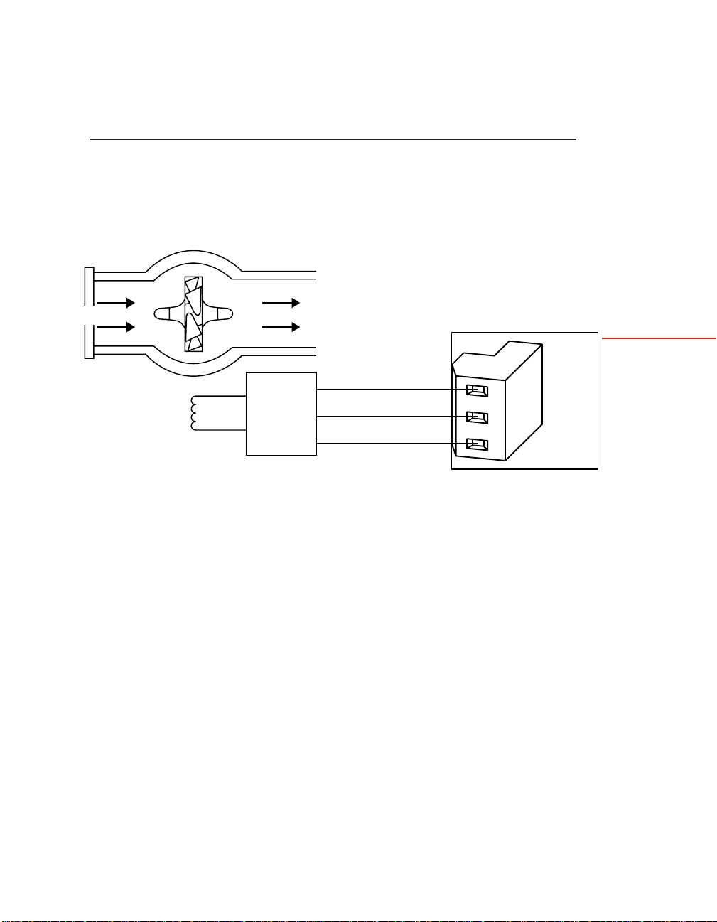
5.6 STEP-BY-STEP PROGRAMMING EXAMPLE 2:
LINEAR FLOW; ADDING TOTAL TO RATE WITH
EXCITATION FROM THE BASIC METER
In this example, the pulse source is a 100-pulse-per-gallon linear
flowmeter (i.e., a turbine meter) which is powered by the unregulated 16 V excitation from the Basic Meter. See Figure 5-2.
TURBINE
5
FLOW
EXCITATION
MAG
PICKUP
Figure 5-2. Basic Meter Connection to a Shaft Position Detector
To demonstrate the meter’s scale and offset capability, set the
RATE display to GPM (gallons per minute), but the TOTAL to
Cubic Feet. This can be done because the decimal point location,
scale factor and offset settings for RATE are completely independent of those for TOTAL.
An external signal (e.g., a limit switch closure or timing pulse) is
connected to P2-3 (RESET-A) and is used to reset the TOTAL.
5.6.1 DETERMINING THE RATE DECIMAL POINT (RTE DP) AND RATE SCALE (RTE SC)
SENSOR
AMP
SIG IN
SIG RETURN
1
2
3
P3
METER
Configuring
the Meter
Once again the pulse source does not have an offset, so the only
RATE parameters to be set are the decimal point (RTE DP) and
scale factor (RTE SC).
Selecting the RTE DP position as RRRR.RR gives a possible full
scale reading of 9999.99 GPM, or (dividing by 60) 166.67 gal/s.
With 100 pulses per gallon, the maximum pulse rate would be
16.67 kHz.
85
 Loading...