

Page 1
am
a-
Q
m
@
A
y
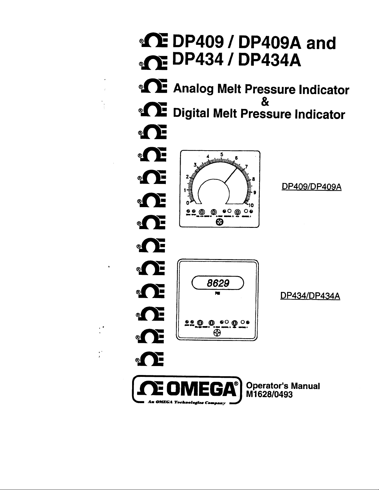
DP409
DP434
DP409A
/
DP434A
I
and
Analog Melt Pressure Indicator
&
Digital Melt Pressure Indicator
459 ’
3
2
1
7
a
9
DP409/DP409A
0
ee@
--am”-.
@
00@00
._I,
t3
10
_I. .
Page 2
OMEGA? .. Your Source for
Process Measurement and Control
TEMPERATURE
&
&
M
0’
Wire: Thermocouple, RTD
&
M
Calibrators
M
Recorders, Controllers
0’
infrared Pyrometers
Ice Point References
Thermistor Probes, Connectors, Panels Themocoupie, RTD
&
Thermistor
&
Process Monitors
PRESSURE/STRAIN FORCE
0’
Transducers & Strain Gauges
&
I2
Load Cells
I2
Displacement Transducers
I2
instrumentation
Pressure Gauges
&
Accessories
FLOW/LEVEL
II?
Rotameters, Gas Mass Flowmeters
IZ?
Air Velocity indicators
Ca
TurbinelPaddiewheei
&
M
Totaiizers
Batch Controllers
Systems
pH/CONDUCTIVITY
&
pH
Electrodes, Testers
Gf
[a
BenchtoplLaboratory
0’
Controllers, Calibrators, Simulators
I2
industrial
&
Conductivity Equipment
pH
Accessories
Meters
&
Flow Computers
8 Pumps
Assemblies
DATA ACQU ISITION
II@
Data Acquisition and Engineering Software
IET
Communications-Based Acquisition Systems
&
I2
Plug-in Cards for Apple, IBM
[a
Datalogging Systems
&
I33
Recorders, Printers
Plotters
Compatibles
HEATERS
0’
Heating Cable
&
I@
Cartridge
0’
immersion & Band Heaters
I% Flexible Heaters
0’
Laboratory Heaters
Strip Heaters
Page 3
TABLE OF CONTENTS
DP409
DP434
DP409
ANALOG MELT PRESSURE INDICATOR
DIGITAL MELT PRESSURE INDICATOR
ANALOG MELT PRESSURE INDICATOR
SECTION
SECTION 1 DESCRIPTION
SECTION 2 UNPACKING
3
SECTION
3.1
3.2
PARTS OF THE PRESSURE TRANSDUCER . . . . . . . . . . . 1
Front
Rear
. . . . . . . . . . . . . . . . . . . . . . . . . . . . . . . . . . . . . . . . . . . . . . . . . . . . . . . . . . . . . . . . . . . . . . . . . . . . . . . . . . . . . . . . . . . . .
. . . . . . . . . . . . . . . . . . . . . . . . . . . . . . . . . . . . . . . . . . . . . . . . . . . . . . . . . . . . . . . . . . . . . . . . . . . . . . . . . . . . . . . . . . . . . . .
SECTION 4 INSTALLATION
4.1
SECTION
5.1
5.2
5.3
installation Wiring
5
ADJUSTMENTS
Description .....................................................................................
Procedure
Adjustments
......................................................................................
. . . . . . . . . . . . . . . . . . . . . . . . . . . . . . . . . . . . . . . . . . . . . . . . . . . . . . . . . . . . . . . . . . . . . . . . . .
DP409A
-
PAGE
. . . . . . . . . . . . . . . . . . . . . . . . . . . . . . . . . . . . . . . . . . . . . . . . . . . . . . . . . . . .
. . . . . . . . . . . . . . . . . . . . . . . . . . . . . . . . . . . . . . . . . . . . . . . . . . . . . . . . . . . . . .
. . . . . . . . . . . . . . . . . . . . . . . . . . . . . . . . . . . . . . . . . . . . . . . . . . . . . . . . . .
-
ZERO AND SPAN
Control
Setpoints
......................................
. . . . . . . . . . . . . . . . . . . . . . . .
1
1
1
2
3
3
5
5
5
6
SECTION 6 OPTION SWITCH
6.1
6.1.1
6.1.2 Calibration Shunt
6.1.3 Filter (Damping Circuit), Amp Board ..............................................
6.1.4
6.2
6.2.1
6.2.2
Amplifier Board on
Transducer
Recorder Output Select, Amp Board
Logic Option Board on
Setting of Control 1 and/or 2 Setpoints
Reset (Automatic/Manual), Logic Option Board
Sensitivity,
DP409/DP409A
Resistor,
SECTION 7 TROUBLESHOOTING
SECTION 6 SPECIFICATIONS
9
SECTION
OPTION WORKSHEETS AND SUMMARY
SElTlNGS
Board
Amp
Amp Board .........................................
DP409A
.....................................................
. . . . . . . . . . . . . . . . . . . . . . . . . . . . . . . . . . . . . . . . . . . . .
. . . . . . . . . . . . . . . . . . . . . . . . . . . . . . . . . . . . . . . . . . . . . . . . . . . .
....................................
...............................................
...............................................
.............................................
..........................................
.......................... 10
. . . . . . . . . . . . . 12
6
6
7
7
8
8
8
8
10
11
Page 4
TABLE OF CONTENTS (CONT ’D)
DP409
DP434
DP434
ANALOG MELT PRESSURE INDICATOR
DIGITAL MELT PRESSURE INDICATOR
DIGITAL MELT PRESSURE INDICATOR
SECTION
SECTION 10 DESCRIPTION
SECTION 11 UNPACKING
12
SECTION
12.1
12.2
Front
Rear
PARTS OF THE PRESSURE TRANSDUCER..
............................................................................................
.............................................................................................
........................................................
..........................................................
SECTION 13 INSTALLATION
13.1
SECTION
14.1
14.2
installation Wiring .........................................................................
14
ADJUSTMENTS
Description
Procedure
...................................................................................
....................................................................................
PAGE
.15
....
............................................
-
ZERO AND SPAN
.........
.I9
15
15
15
16
17
17
19
19
SECTION
15.1
15.1.1
15.1.2
151.3
15.1.4
15.2
15.2.1
15.2.2
15.3
15.4
15.4.1
15.4.2
Amplifier Board
Transducer Sensitivity, Amp Board
Calibration Shunt Resistor
Filter (Damping Circuit), Amp Board
Recorder Output Select, Amp
Display and Logic Option Boards
Decimal Point, Display Board
Range Select, Logic Option
Adjust men ts
Logic Option Board on
Setting of Control 1 and/or 2 Setpoints
Reset (Automatic/Manual), Logic Option Board
15
OPTION SWITCH
DP434/DP434A
on
DP434A Control Setpoints
-
DP434A
SElTlNGS
...........................................................
Board
................................................
......................................................
&
Display Boards
....................................................
SECTION 16 TROUBLESHOOTING
SECTION
17 SPECIFICATIONS
........................................
.............................................
..............................................
...........................................
...........................................
........................................
.................................
......................
............................
....................................
...........................
SECTION 18 OPTION WORKSHEETS AND SUMMARY
ii
20
20
20
21
21
22
22
22
23
23
24
24
25
26
26
.28
Page 5
SECTION 1 DESCRIPTION
DP409
The OMEGA
transducer power supply, indicator and signal conditioner. The
%
DIN standard size case of extruded aluminum protects against
RFI noise, heat dispersion and physical damage. The
is styled for ease of reading and incorporates an intematronal face.
Analog Melt Pressure Transducer is a combination
6”:
240 degree meter
DP409
DP409
EMI
and
The DP409 is designed for use with an OMEGA pressure transducer or any
4-169,
350 ohm wheatstone bridge strain
push-button allows for span adjustment w ile you adjust zero at zero
pressure. The complete electronic assembly can be removed and/or
replaced from the front panel for convenient service and option selection.
Options include dual setpoints and auxiliary outputs for recorders, remote
indicators or a computer interface. The dual
the letter “A”
shutdown sequence is initiated, thereb
prevent accidental shutdown, the act o
will not actuate the alarm relays.
(DP409A),
can be used to give a warning before an actual
age transducer. A calibration
%
setpoint
reducing or avoiding downtime. To
Y
setting of the
option, designated by
setpoint
or calibration
SECTION 2 UNPACKING
Remove the Packing List and verify that all equipment has been received.
there are any questions about the shipment, please call the OMEGA
Customer Service Department at l-800-622-2378 or (203) 359-l 660.
U
on receipt of shipment, inspect the container and equipment for any signs
P
damage. Take particular note of any evidence of rough handling in
o
transit. Immediately report any damage to the shipping agent.
NOTE
claims
The canter will not honor any
their examination. After examining and removing contents, save packing
material and carton in the event reshipment is necessary.
unless all shipping material is saved for
SECTION 3 PARTS OF THE MELT PRESSURE TRANSDUCER
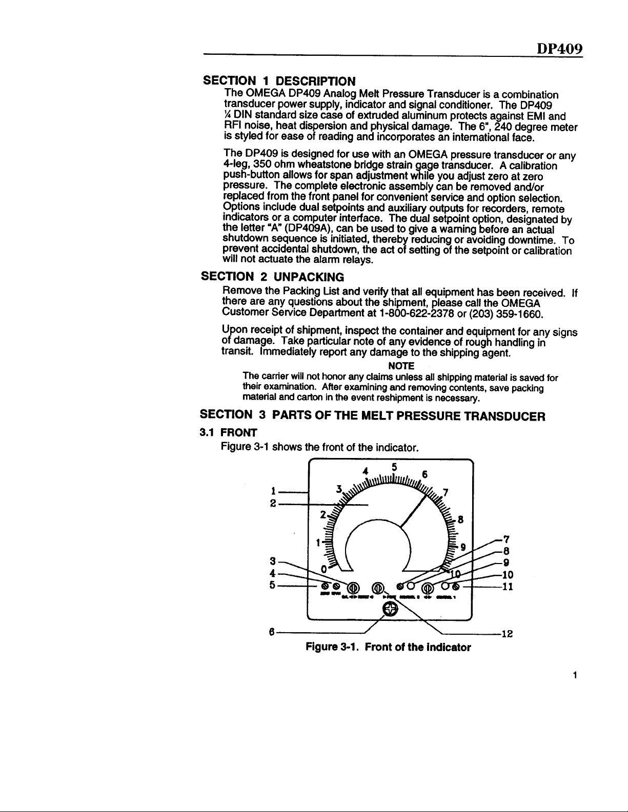
3.1 FRONT
Figure 3-1 shows the front of the indicator.
If
Figure 3-1. Front
of the indicator
1
Page 6
DP409
KEY
1
2
3
4
5
6
7
8
9
10
DESCRIPTION
l/ 4
D IN
Enclosure.
Large Analog Display with
p ressu re and con tr o l
p ressu re to fu ll- sca le r ange .
Ca lib ra ti on
ad jus t span fo r ca li b ra ti on p ressu re o f tr ansduce r and to rese t con tr o l
a la rm s when con fi gu red fo r m anua l r ese t.
Selector/Reset Toggle Switch.
Span Potentiometer.
con junc ti on w it h ca li b ra ti on /r ese t s w it ch .
Ze ro Po ten ti o m e te r. U sed to ra ise /t owe r ze ro ca li b r a ti on po in t on
d isp lay .
Access
access to in te r na l D IP sw it ches .
Screw.
Control 2 Potentiometer.
se tpo in t.
Fa ; F ti
Con tr o l l/ Con tr o l 2 Se lec to r Togg le Sw it ch . Used to d isp lay and
ad jus t Con tr o l 1 and Con tr o l 2 se tpo in ts .
Ea ;n t;
2 A la rm Ind ica ti on LED . L igh ts when Con tr o l 2
1 A la rm Ind ica ti on LED . L igh ts when Con tr o l 1
O u te r case d im ens ions
240”
dial indication.
a la rm
se tpo in ts . Shows re la ti on o f ope r a ti ng
U sed to ra ise /l owe r ca li b ra ti on p r essu r e in
Unsc r ew to re m ove ind ica to r fr o m enc losu re to ga in
U sed to r a ise /lowe r Con tr o l 2 a la rm
Ind ica tes ope r a ting
U sed to d isp lay and
se tpo in t
se tpo in t
i s
i s
11
Con tr o l Po ten ti o m e te r. U sed to ra ise /t owe r Con tr o l 1 a la rm se tpo in t.
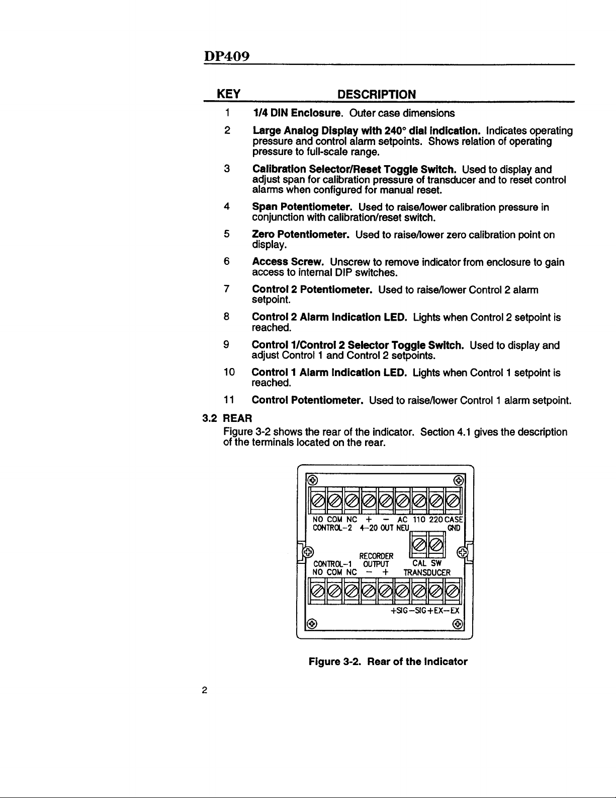
3 .2 REAR
F igu re 3 -2 shows the rea r o f t he ind ica to r. Sec ti on 4 .1 g ives the desc ri p ti on
o f t he te rm ina ls loca ted on the rea r.
-
COM
NO
oNma-
Figure
NC
+
3 -2 .
AC 110 220CASE
4-20 OUT NEU
+SlG-SlG+EX-
Rear of the Indicator
Page 7
DP409
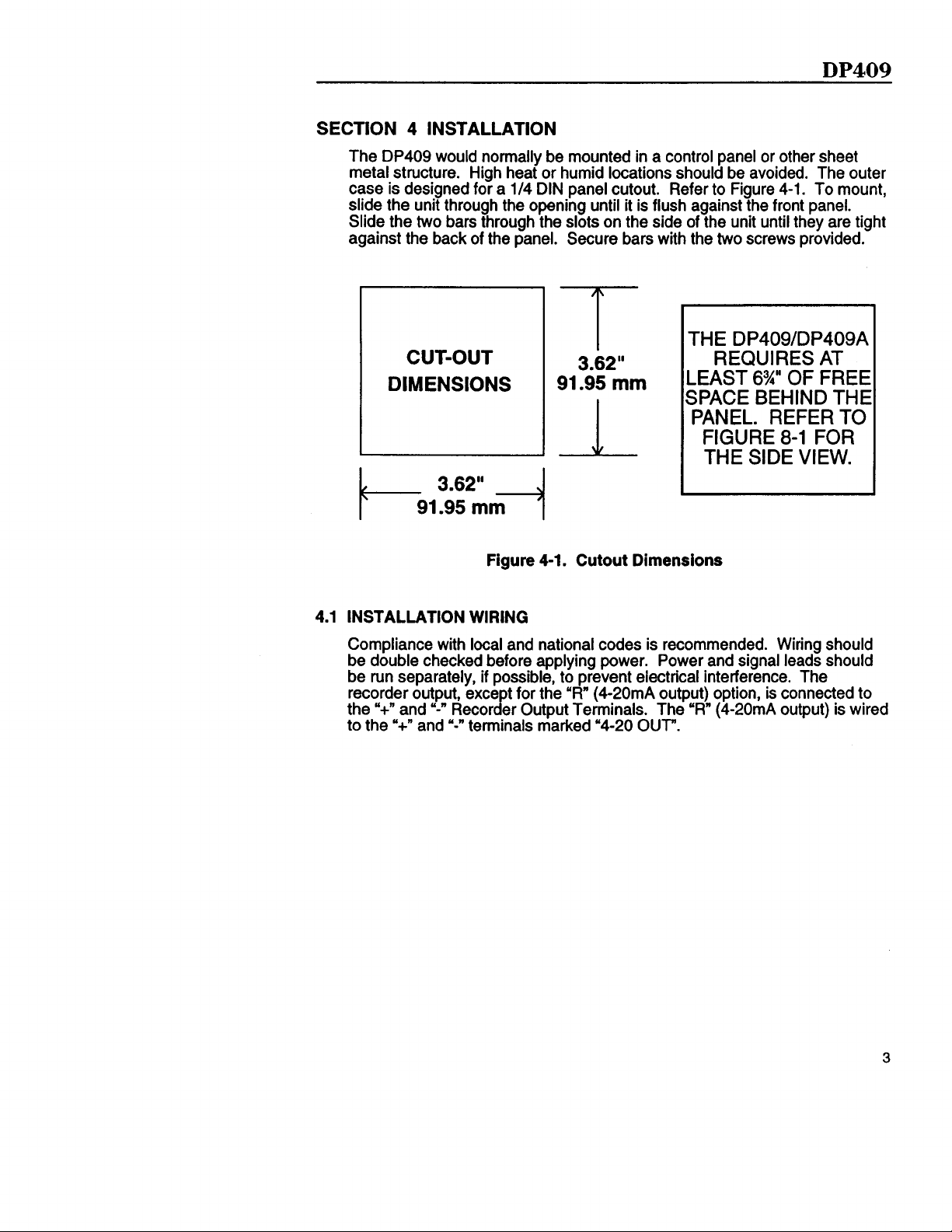
SECTION 4 INSTALLATION
DP409
The
metal structure. High heat or humid locations should be avoided. The outer
case is designed for a
slide the unit through the opening until it is flush against the front panel.
Slide the two bars through the slots on the side of the unit until they are tight
against the back of the panel. Secure bars with the two screws provided.
would normally be mounted in a control panel or other sheet
l/4
DIN panel cutout. Refer to Figure 4-1. To mount,
THE
DP409/DP409A
REQUIRES AT
-EAST
SPACE
6%” OF FREE
BEHIND THE
CUT-OUT
DIMENSIONS
T
3.62”
91.95
mm
PANEL. REFER TO
FIGURE
8-l FOR
THE SIDE VIEW.
Figure 4-1. Cutout Dimensions
4.1 INSTALLATION
Compliance with local and national codes is recommended. Wiring should
be double checked before applying power. Power and signal leads should
be run separately, if possible, to prevent electrical interference. The
recorder output, except for the
‘+”
and
the
‘+” and
to the
WIRING
“R”
(4-20mA output) option, is connected to
y-n
Recorder Output Terminals. The
“-”
terminals
marked
“4-20
OUT ”.
(4-20mA
“R”
output) is wired
3
Page 8
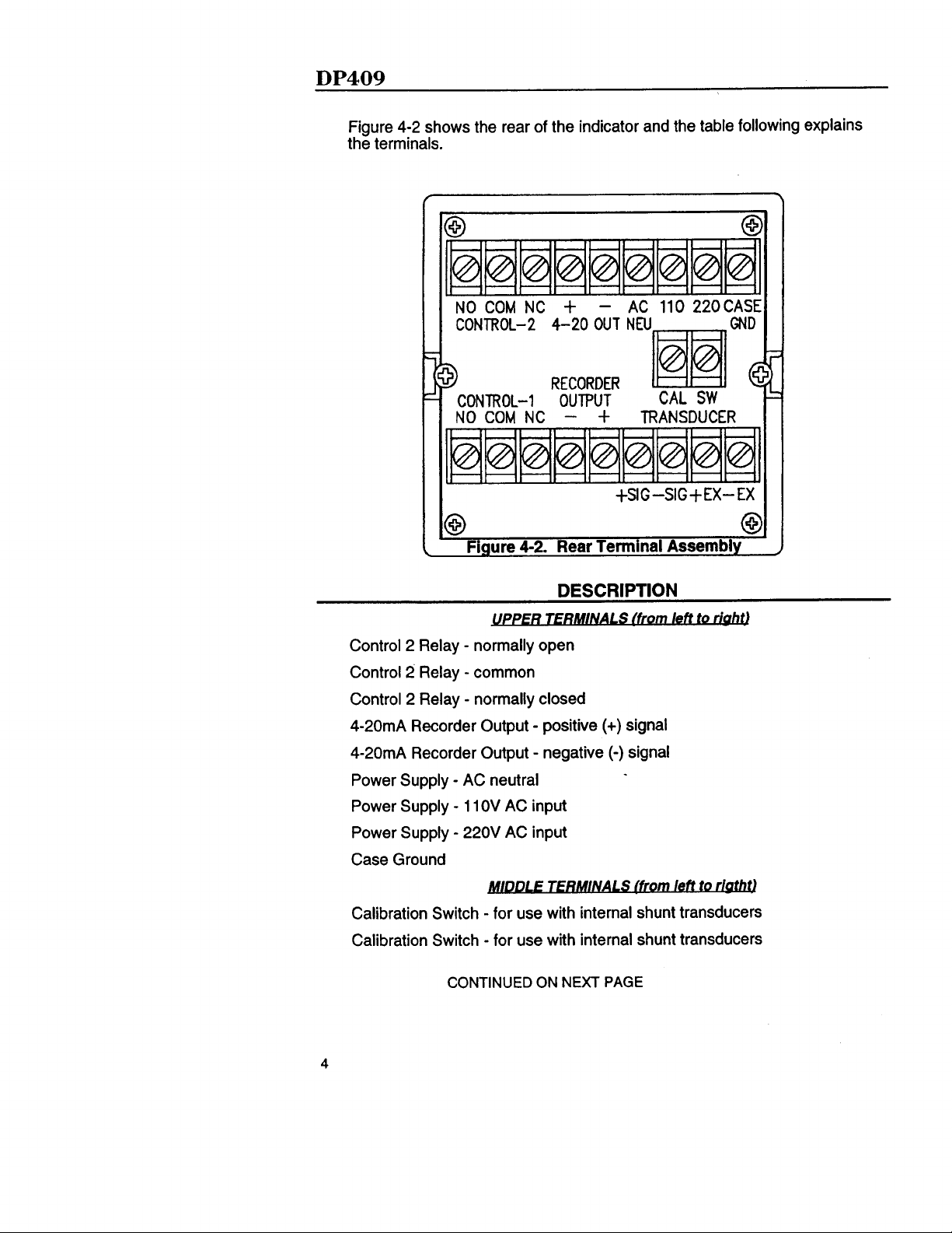
Figure 4-2 shows the rear of the indicator and the table following explains
the terminals.
-
i
NO COM NC +
4-20 OUT
AC 110 220CASE
GND
1
NO COM NC
@
Control 2 Relay
Control 2 Relay
Control 2 Relay
4-20mA
4-20mA
Power Supply
Power Supply
Power Supply
Recorder Output
Recorder Output
-
AC neutral
-
11 OV AC input
-
220V AC input
RECORDER
@
OUTPUT
-
+ TRANSDUCER
‘1
u
‘1
11
‘1
+SIG-SIG+EX-EX
0
0.
Figure 4-2. Rear Terminal Assembly
DESCRIPTION
-
normally open
-
common
-
normally closed
-
positive (+) signal
(-)
-
negative
signal
Case Ground
Calibration Switch
Calibration Switch
4
-
for use with internal shunt transducers
-
for use with internal shunt transducers
CONTINUED ON NEXT PAGE
Page 9
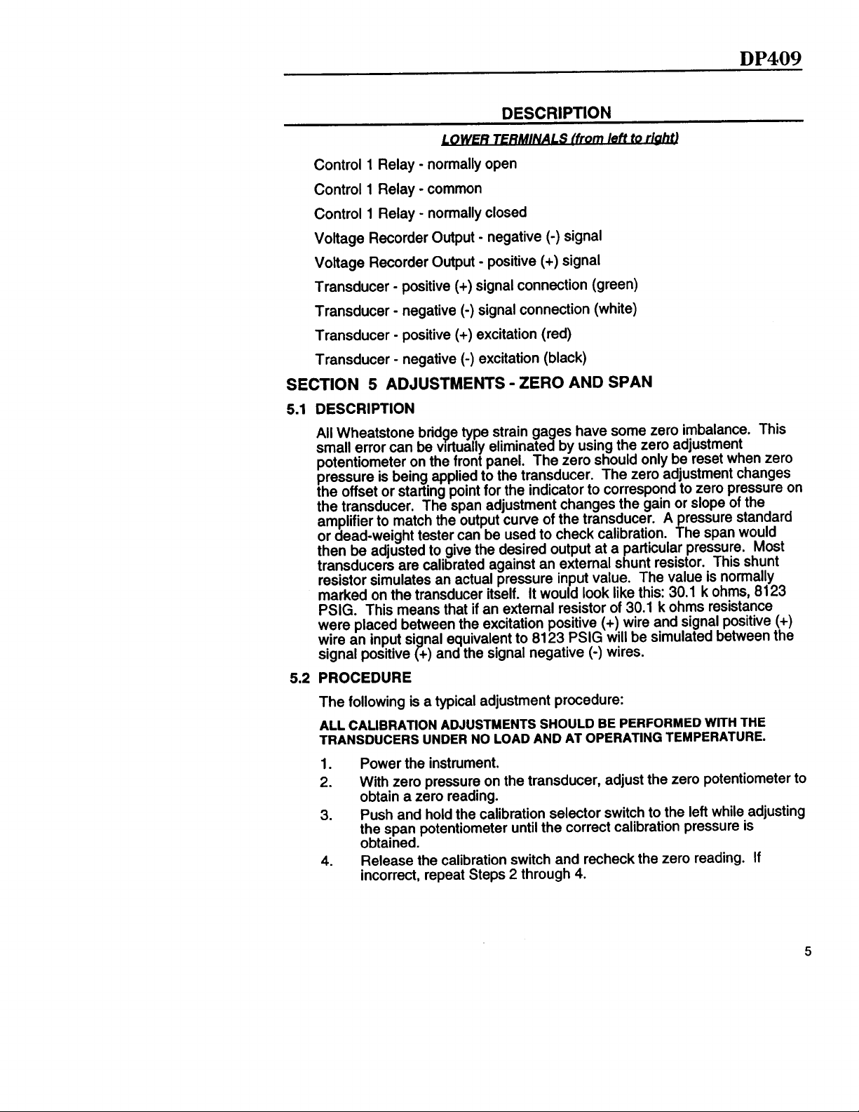
Control 1 Relay
TS
-
normally open
DESCRIPTION
lDWFR
left
to
nbhtl
DP409
Control 1 Relay
Control 1 Relay
Voltage Recorder Output
Voltage Recorder Output
Transducer
Transducer
Transducer
Transducer
SECTION 5 ADJUSTMENTS
5.1
DESCRIPTION
All Wheatstone bridge type strain gages have some zero imbalance. This
small error can be
potentiometer on the front panel. The zero should only be reset when zero
pressure is being applied to the transducer. The zero adjustment changes
the offset or starting point for the indicator to correspond to zero pressure on
the transducer. The span adjustment changes the gain or slope of the
amplifier to match the output curve of the transducer. A
or dead-weight tester can be used to check calibration.
then be adjusted to give the desired output at a particular pressure. Most
transducers are calibrated against an external shunt resistor. This shunt
resistor simulates an actual pressure input value. The value is normally
marked on the transducer itself. It would look like this: 30.1 k ohms, 8123
PSIG. This means that if an external resistor of 30.1 k ohms resistance
were placed between the excitation positive (+) wire and signal positive (+)
wire an input si nal equivalent to 8123
signal positive +) and the signal negative
PROCEDURE
5.2
-
common
-
normally closed
(-)
-
negative
-
positive (+) signal
-
positive (+) signal connection (green)
(-)
-
negative
-
positive (+) excitation (red)
-
negative
?
signal connection (white)
(-)
excitation (black)
-
ZERO AND SPAN
vrrtually
eliminated by using the zero adjustment
signal
PSIG
will be simulated between the
(-)
wires.
ressure standard
P
he
span would
The following is a typical adjustment procedure:
ALL CALIBRATION ADJUSTMENTS
TRANSDUCERS UNDER NO LOAD AND AT OPERATING TEMPERATURE.
1.
Power the instrument.
2.
With zero pressure on the transducer, adjust the zero potentiometer to
obtain a zero reading.
3.
Push and hold the calibration selector switch to the left while adjusting
the span potentiometer until the correct calibration pressure is
obtained.
4.
Release the calibration switch and recheck the zero reading. If
incorrect, repeat Steps 2 through 4.
SHOULD BE PERFORMED WITH THE
Page 10

DP409
5.
The electrical zero may be checked any time the transducer is at zero
pressure. This may be necessary after heat-up to correct any thermal
zero shift of the transducer.
NOTE
DO NOT CHANGE THE SPAN CALIBRATION WHEN THERE IS
PRESSURE ON THE TRANSDUCER. IF THIS IS DONE, THE
PRESSURE READING MAY
BE IN ERROR.
DP409A
-
5.3 ADJUSTMENTS
DP409A
The
one relay to trigger an auxiliary alarm, corrective action can be taken before
mandatory shut-down is reached. The second relay circuit can then be used
for mandatory shut-down.
CONTROL 1
1.
Push and hold the control selector switch to the right.
2.
Adjust the Control 1 potentiometer until the desired control pressure is
displayed on the indicator.
3.
Release the selector toggle switch.
CONTROL 2
1.
Push and hold the control selector switch to the right.
2.
Adjust the Control 2 potentiometer until the desired control pressure is
displayed on the indicator.
3.
Release the selector toggle switch.
SECTION 6 OPTION SWITCH SETTINGS
6.1 AMPLIFIER BOARD ON
Figure 6-1 shows the location of DS4 and DS5 on the Amplifier Board.
provides two separate setpoints circuits and relays. By using
CONTROL SETPOINTS
DP409/DP409A
El
pmm l
DS5
I
m l
DS4
I
III
b
I
f-
Figure 6-1. Amplifier Board
6
Page 11
DP409
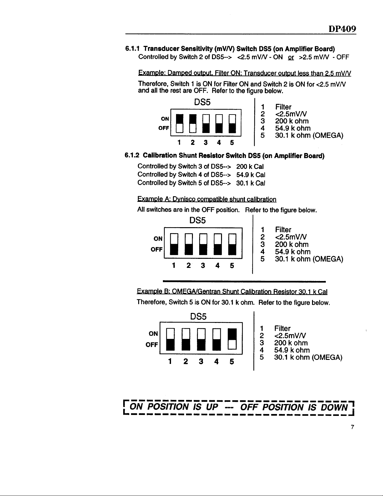
.l
Transducer Sensitivity
6.1
Controlled by Switch 2 of
Dued
ble:
Therefore, Switch 1 is ON for Filter ON and Switch 2 is ON for
and all the rest are OFF. Refer to the figure below.
or&~,&
(mV/V)
Filter
DS5
6.1.2 Calibration Shunt Resistor Switch
com&le
DS5-->
DS5-->
DS5-->
Controlled by Switch 3 of
Controlled by Switch 4 of
Controlled by Switch 5 of
*
.
Dvnrsco
ale
A.
All switches are in the OFF position.
Switch DS5 (on Amplifier Board)
PI
-
mV/V
~2.5
DS5-->
ON: Transducer
shunt
DS5
200 k Cal
54.9 k Cal
30.1 k Cal
ca
Refer to the figure below.
ON
oum
less than
1
Filter
<2.5rnVN
2
3 200 k ohm
54.9kohm
4
5 30.1 k ohm
(on Amplifier Board)
..
DS5
~2.5
-
OFFmVN
3
5
mVN
~2.5
(OMEGA)
mVN.
i%~
;
o;pgq
3011
5
k ohm (OMEGA)
1 2 3 4 5
n Shunt Calibration Resistor 30.1 k
Therefore, Switch 5 is ON for 30.1 k ohm. Refer to the figure below.
DS5
111~1~1111~~11111111~~~~~~~~
I
Caj
DOWN:
IS CON POSITION IS UP -- OFF POSITION
111~11111~1111111111llllllll
7
Page 12

DP409
6.1.3 Filter (Damping Circuit) Switch DS5 (on Amplifier Board)
Controlled by Switch 1 of
DS5-->
Filter ON, slower response, 5 seconds
Fifter
OFF, fast response,
113
DS5
~~e5’rnVlV
i
oj.mkq
1
2 3 4 5
6.1.4 Recorder Output Select Switch DS4 (on Amplifier Board)
3 20b koh m
4 54.9 k ohm
5
30.1 k ohm (OMEGA)
second
Controlled by Switch 1 of
Controlled by Switch 2 of
Controlled by Switch 3 of
Controlled by Switch 4 of
)
Volt DC required
Therefore, Switch 2 is ON for 5
the figure below.
DS4-->
O-10 Volts DC
DS4-->
DS4-->
DS4-->
Volts
O-5 Volts DC
O-2 Volts DC
O-l Volt DC
DC and all the rest are OFF.
DS4
o:mi
1
2 3 4
6.2 LOGIC OPTION BOARD ON
6.2.1 Setting of Control 1 and/or 2 Setpoints
Figure 6-2 shows the location of
DP409A
ONLY
DSl
and DS2 on the Logic Option Board.
;
Switch
!gicJ
_
DSl (on Logic Bd)
ml
~lieesleaeaass~
DSl
DS2
Refer to
Figure 6-2. Logic Option Board
1111111111111~1111~1~~~~~~~~
1-1
[ON
POSITION IS UP
OFF POSITION IS
1111111111111~111111~~~~~~~~
DOWN:
Page 13

DP409
Controlled by Switches 1 and 4 of
Controlled by Switches 2 and 3 of
Controlled by Switches 5 and 8 of
Controlled by Switches 6 and 7 of
”
A: Controls 1 and
Therefore, Switches
1,4,5,
above
7
ON
and 8 are ON and the rest are OFF. Refer to
the figure below.
DSl
1234567 0
ale
B:
Control 1 ON “below”
Therefore, Switches
the figure below.
1,4,6,
setgotnt
and 7 are ON and the rest are OFF. Refer to
DSl
DSl-->
-->
DSl
-->
DSl
-->
DSl
(1
setDot&
Control 2 for above
Control 2 for below
Control 1 for above
Control 1 for below
setooints,
ContrQL2
and
ON
Y
above
setpoint
setpoint
setpoint
setpoint
n
1234567 8
le C:
Controls 1 and 7 ON below ”
Therefore, Switches
the figure below.
1234567 8
setpoir&
2,3,6,
and 7 are ON and the rest are OFF. Refer to
Page 14

DP409
D: Control 1 ON
Therefore, Switches
Y
2,3,5,
n
seto
aboveExamDIe
oint and
mtrol7
ON “below”
and 8 are ON and the rest are OFF. Refer to
the figure below.
DSl
ON
OFF
I
1234567 8
6.2.2
Reset (Auto/Manual Reset) Switch DS2 (on Logic Option Board)
Controlled by Switch 1 of
Controlled by Switch 2 of
Controlled by Switch 3 of
Controlled by Switch 4 of
JZxample:
Manual Reset on Control
DS2-->
DS2-->
DS2-->
DS2-->
Control 1 Auto Reset
Control 2 Auto Reset
Control 2 Manual Reset
Control 1 Manual Reset
Control
on
1
and
Reset
Therefore, Switches 2 and 4 are ON for and all the rest are OFF. Refer to
the figure below.
DS2
se-
Z
1 2 3 4
NOTE: CONTROL LOGIC CANNOT OCCUPY TWO STATES AT ONCE. WHEN
DESIRED RESET MODE IS
MODE SHOULD BE SWITCHED OFF. (I.E.;
SWITCHED ON, CONTROL
SWlTCHED
1
MANUAL RESET SHOULD BE SWITCHED OFF.)
ON, ALTERNATE CORRESPONDING
IF
CONTROL
1
AUTO
RESET/S
SECTION 7 TROUBLESHOOTING
PROBLE M
Indicator pegs full scale.
Cannot adjust zero low Transducer over-pressured. Check
enough.
i
ON POSITION IS UP -- OFF POSITION IS DOWN
i0
Opening in
transducer.
cable is removed from transducer.)
transducer.
SOLUTION
wiring between indicator
(NOTE: will occur when transducer
and
;
Page 15

DP409
SECTION 8
POWER:
OPERATING TEMP. RANGE:
DISPLAY:
ACCURACY:
TRANSDUCER POWER SUPPLY:
TRANSDUCER BRIDGE
SHUNT CALIBRATION RESISTOR:
INPUT SENSITIVITIES:
ZERO BALANCE:
RESPONSE TIME:
RECORDER OUTPUTS:
RECORDER OUTPUT ACCURACY:
RECORDER OUTPUT
RECORDER OUTPUT
RECORDER OUTPUT STABILITY:
DIMENSIONS:
WEIGHT:
SPEClFlCATlONS
CIRCUlT:
REPEATABIUTY:
LINEARlTY:
50160
106-l 25VAC or
110
A max.
0”
to 140°F (-17.8 ” to 60°C)
6’ long scale, 240 degree angle
*2.0% full scale
Within
f
8.2VDC
4 leg, 350 ohm nominal resistance
Selectable 30.1 k ohm,
ohm
O-l to O-O.25
DIP-switch selectable
f35%
potentiometer
1M
O-l VDC,
DIP-switch selectable, min. load 5000
ohms
‘R”
set, min. load 15 ohms, max load 600
ohms
fO.l%
within
within
within
Refer to Figure
2.5 pounds (1.134 kg)
5%
adjustable with the front panel
second or 5 seconds selectable
option -- O-20mA or
full scale
fO.l%
fO.l%
fO.l%
200-250VAC,
mVN
0-2VDC,
full
full scale
full scale
8-l
54.9k
and O-2.5 to O-5
OJVDC, O-l OVDC
4-2OmA
scaie
Hz,
ohm, 200k
mV/V
factory
RELAYS:
RELAY RATING:
SETPOINT
ACCURACY:
HYSTERESIS:
INDICATION:
MODE:
RESET:
RANGE:
FRONT VIEW
r
IFlCATlONS
--I--
3.93-
D9.82
mm
1
Figure
2 SPDT (single pole double throw)
8 amps at
30VDC
l-1 00% of full scale
within
within
Front panel
Above or below setpoint, switch selectable
Automatic or manual, switch selectable
8-l.
Dimensions
1251250VAC
*0.3% of full scale
*0.5% of full scale
LEDs
or 5 amps at
11
Page 16

DP409
SECTION 9 OPTION WORKSHEETS AND SUMMARY OF DIP
SWITCH POSITIONS
INSTRUCTIONS: Fill in this page, if desired, with the indicator positions of
the switches (either ON or OFF) within
Refer to this sheet when calling OMEGA for technical
assistance.
DSl and DS2.
LOGIC OPTION BOARD --
DS2
j-mq
1
Reset
Control
Logic
Loaic
2 3 4
--
--
Da
1234567 8
Control 1, Auto Reset
Control 2, Auto Reset
Control 2, Manual Reset
Control 1, Manual Reset
Control 2, Above DSl
Control 2, Below
Control 2, Below
Control 2, Above
Control
Control
Control
Control
1,
1,
1,
1,
DP409A
DSl
Above
Below
Below
Above
Setpoint
Setpoint
ONLY
Setpoint
Setpoint
Setpoint
Setpoint
Setpoint
Setpoint
12
NOTES
Page 17

.
INSTRUCTIONS: Fill in this page, if desired, with the indicator positions of
the switches (either ON or OFF) within DS4 and DS5.
Refer to this sheet when calling OMEGA for technical
assistance.
DP409A
&
AMP BOARD -- DP409
DP409
o$ imq
1
Filter.
Transducer
t Calibration
Recorder Output
Sensitivitv,
DS5
2 3 4
DSs
_
_
DS4
:p m iq
5
1
Filter (Damping)
mVN Transducer Output
~2.5
2
3
4
5
1
2 O-5 Volts DC
3
4
200 k Cal
54.9 k Cal
k Cal
30.1
O-l 0 Volts DC
O-2 Volts DC
O-l Volt DC
NOTES
1
DS4
2 3
4
13
Page 18

DP409
NOTES
14
Page 19

DP434
SECTION 10 DESCRIPTION
The OMEGA DP434 Digital Melt Pressure Transducer is a combination
.
transducer power supply, indicator and signal conditioner. The DP434
EMI
%
DIN standard size case of extruded aluminum protects against
RFI noise, heat dispersion and physical damage. The 0.3 ” LED display
gives a clear indication, readable even from a distance.
The DP434 is designed for use with an OMEGA pressure transducer or any
4-leg,
350 ohm wheatstone bridge strain gage transducer. A calibration
push-button allows for span adjustment while you adjust zero at zero
pressure. The complete electronic assembly can be removed and/or
replaced from the front panel for convenient service and option selection.
Options include dual setpoints and auxiliary outputs for recorders, remote
indicators or a computer interface. The dual
the letter “A”
shutdown sequence is initiated, thereb
prevent accidental shutdown, the act o
will not actuate the alarm relays.
(DP434A),
can be used to give a warning before an actual
reducing or avoiding downtime. To
Y
setting of the
setpoint
option, designated by
setpoint
or calibration
SECTION 11 UNPACKING
Remove the Packing List and verify that all equipment has been received.
there are any questions about the shipment, please call the OMEGA
Customer Service Department at l-800-622-2378 or (203) 359-l 660.
Upon receipt of shipment, inspect the container and equipment for any signs
of damage. Take particular note of any evidence of rough handling in
transit. Immediately report any damage to the shipping agent.
NOTE
The carrier will not honor any claims unless ail shipping material is saved for
their examination. After examining and removing contents, save packing
material and carton in the event reshipment is necessary.
and
If
SECTION 12 PARTS OF THE MELT PRESSURE TRANSDUCER
12.1 FRONT
Figure 12-1 shows the front of the indicator.
Figure
12-1. Front of the indicator
15
Page 20

DP434
KEY
1
2
3
4
5
6
7
8
9
10
DESCRIPTION
l/4
DIN Enclosure Outer case dimensions.
LEDs.
Large Digital Display with
ope ra ti ng p ressu re and con tr o l ala rm
Calibration Selector/Reset Toggle Switch.
ad jus t span fo r ca li bra tion p ressure o f tr ansducer and to rese t con tr o l
a la rm s when con fi gu red fo r m anua l r ese t.
Span Potentiometer.
con junc tion w it h ca lib ra tion /r ese t s w it ch .
Zero
Po ten ti om e te r. Used to ra ise /l owe r ze ro ca li bra tion po in t on
d isp lay .
Access Sc rew . Unsc rew to re m ove ind ica to r fr o m enc losu re to ga in
access to in te rna l D IP sw it ches .
Con tr o l 2 Po ten ti om e te r. Used to ra ise /l owe r Con tr o l 2 a la rm
se tpo in t.
Con tr o l 2 A la rm Ind ica ti on LED . L igh ts when Con tr ol 2
reached .
high efficiency
setpolnts.
U sed to ra ise /t owe r ca li bra ti on p ressure in
Control l/Control 2 Selector Toggle Switch.
ad jus t Con tr o l 1 and Con tr o l 2 se tpo in ts .
Con tr o l 1 A la rm Ind ica ti on LED . L igh ts when Con tr ol 1
reached .
I nd ica tes
Used to d isp lay and
se tpo in t
U sed to d isp lay and
se tpo in t
i s
i s
Con tr o l Po ten ti o m e te r. Used to ra ise /l owe r Con tr o l 1 a la rm se tpo in t.
11
Peak Hold/Peak Reset Toggle Switch.
12
ho ld m ode and to rese t t he peak pressure .
12.2 REAR
F igu re 12 -2 shows the rea r o f t he ind ica to r. Sec ti on 13 .1 g ives the
descr ip tion o f t he te rm ina ls loca ted on the rea r.
Figure 12-2. Rear of the Indicator
Used to sw itch un it i n to peak
16
Page 21

DP434
SECTION 13
The DP434 would
metal structure. High heat or humid locations should be avoided. The outer
case is designed for a
mount, first remove the screws holding in the slide retainer on the side of the
case. Remove the slide retainers by
Install the indicator into the panel cutout.
their slots. Install the screws and tighten enough to hold the indicator in
INSTALLAnON
normally
be mounted in a control panel or other sheet
l/4
DIN panel cutout. Refer to Figure 13-l. To
slidin
them toward the rear of the unit.
lide the slide retainers back into
8
THE DP434
CUT-OUT
DIMkNSIONS
7-
3.62”
91.95
mm
REQUIRES AT
LEAST 6%” OF
FREE SPACE
BEHIND THE
‘ANEL. REFER TO
FIGURE 17-1 FOR
THE SIDE VIEW.
Figure 13-l. Cutout Dimensions
13.1 INSTALLATION WIRING
Compliance with local and national codes is recommended. Wiring should
be double checked before applying power. Power and signal leads should
be run separately, if possible, to
recorder o
‘+”
and
the
u+n
to the
and
lr!F
ut,
Recor
-”
“-”
t
for the
exce
g
er Output Terminals. The
terminals marked
revent electrical interference. The
#f$
(4-20mA
V-20
output) option, is connected to
OUT”.
(4-20mA
‘R”
output) is wired
17
Page 22

DP434
Figure 13-2 shows the rear of the indicator and the table following explains
the terminals.
3
CONTROL-
NO COM
-1
NC
U
ii
9
3
F iaure 13-2. Rear Ter m ina l
-
Control 2 Relay
Control 2 Relay
Control 2 Relay
4-20mA
4-20mA
Power Supply
Power Supply
Power Supply
Case Ground
Calibration Switch
Recorder Output
Recorder Output
normally open
-
common
-
normally closed
-
AC neutral
-
11
-
220V AC input
I I I I II II II
+SiG-SIG+EX-EX
II II
Asse mb ly
DESCR IPT ION
-
positive (+) signal
(-)
-
negative
OV AC input
-
for use with internal shunt transducers
signal
01
lJ
1
Q
Calibration Switch
CONTINUED ON NEXT PAGE
18
-
for use with internal shunt transducers
Page 23

DP434
DESCRIPTION
r@btI
to
lQWFR
-
Control 1 Relay
Control 1 Relay
Control 1 Relay
normally open
-
common
-
normally closed
Voltage Recorder Output
Voltage Recorder Output
-
Transducer
Transducer
Transducer
Transducer
positive (+) signal connection (green)
-
negative
-
positive (+) excitation (red)
-
negative
SECTION 14 ADJUSTMENTS
TFRs
(-)
-
negative
-
positive (+) signal
(-)
signal connection (white)
(-)
excitation (black)
-
signal
ZERO AND SPAN
14.1 DESCRIPTION
All Wheatstone bridge type strain ga
small error can be virtually eliminate
potentiometer on the front panel. The zero should only be reset when zero
pressure is being applied to the transducer. The zero adjustment changes
the offset or starting point for the indicator to correspond to zero pressure on
the transducer. The span adjustment changes the gain or slope of the
amplifier to match the output curve of the transducer. A
or dead-weight tester
can
be used to check calibration.
then be adjusted to give the desired output at a
transducers are calibrated against an external s
resistor simulates an actual pressure input value. The value is normally
marked on the transducer itself. It would look like this: 30.1 k ohms, 8123
PSIG. This means that if an external resistor of 30.1 k ohms resistance
were placed between the excitation positive (+) wire and signal positive (+)
wire an input si
signal positive +) and the signal negative
14.2
PROCEDURE
nal equivalent to 8123
a
es have some zero imbalance. This
by using the zero adjustment
i
PSIG
will be simulated between the
(-)
wires.
ressure standard
he span would
P
articular
unt resistor. This shunt
1
pressure. Most
The following is a typical adjustment procedure:
WtTH
ALL CALIBRATION ADJUSTMENTS SHOULD BE PERFORMED
TRANSDUCERS UNDER NO LOAD AND AT OPERATING TEMPERATURE.
1.
Power the instrument.
2.
With zero pressure on the transducer, adjust the zero potentiometer to
obtain a zero reading.
3.
Push and hold the calibration selector switch to the left while adjusting
the span potentiometer until the correct calibration pressure is
obtained.
THE
19
Page 24

DP434
4.
Release the calibration switch and recheck the zero reading. If
incorrect, repeat Steps 2 through 4.
5.
The electrical zero may be checked any time the transducer is at zero
pressure. This may be necessary after heat-up to correct any thermal
zero shift of the transducer.
NOTE
DO NOT CHANGE THE SPAN CALIBRATION WHEN THERE IS
PRESSURE ON THE TRANSDUCER. IF THIS IS DONE, THE
PRESSURE READING MAY BE IN ERROR.
SECTION 15 OPTION SWITCH SETTINGS
15.1 AMPLIFIER BOARD ON
Figure 15-l shows the location of DS4 and DS5 on the Amplifier Board.
E l
I
I
Figure 15-l. Amplifier Board
.l Transducer Sensitivity
15.1
Controlled by Switch 2 of
o@ut.
Ded
Therefore, Switch 1 is ON for Filter ON and Switch 2 is ON for
and all the rest are OFF.
DP434/DP434A
I
(mV/V)
DS5-->
Refer to the figure below.
Switch DS5 (on Amplifier Board)
~2.5
-
ON mVN
outout
I
cl
b
pi
less than 2.5 Filter ON: Transducer
I
>2.5
~2.5
I
-
OFFmVN
mVN
mVN
DS5
i
-ml
4
1
2 3 4 5
111111111111~11111~1 llllllll
C-ON
20
POSITION IS UP-- OFF POSITION IS DOWN:
5
ijk&
3011
ohm (OMEGA)
Page 25

DP434
15.1.2 Calibration Shunt Resistor Switch DS5 (on Amplifier Board)
Controlled by Switch 3 of
Controlled by Switch 4 of
Controlled by Switch 5 of
DS5-->
DS5-->
DS5-->
200 k Cal
54.9 k Cal
30.1 k Cal
NOTE: Turn Switches
Dynisco).
Use CAL SW terminals on the back of the indicator for shunting
3,4, and 5 OFF for internal shunt transducers
wiring.
Die
A.
Dylllsco
comoattb!a
shunt
All switches are in the OFF position.
calibration
Refer to the figure below.
’
.
DS5
I
ON
OFF
1
2 3
OMEmentran
8:
ExamDIe
Therefore, Switch 5 is ON for 30.1 k ohm. Refer to the figure below.
5
4
S-ration Resistor 30.1 k Cal
I
1
Filter
<2.5mVtV
2
3 200koh m
4 54.9 kohm
5
30.1 k ohm
(OMEGA)
DS5
1
Filter
ON
OFF
<2.5mViV
2
3 200 k ohm
4 54.9 kohm
5
30.1 k ohm (OMEGA)
(i._e.
15.1.3 Filter (Damping Circuit)
Controlled by Switch 1 of
DS5-->
PI
Switch
DS5 (on Amplifier Board)
Filter ON, slower response,
Filter OFF, fast response,
DS5
$
3 20b k ohm
4 54.9 k ohm
5
IIIIIII__II_II_IIIIIIIII___II
[ON
POSITION IS UP --- OFF POSITION IS
ON
OFF
11111111~~1111111111llllllll
5 seconds
I3
second
1,
Z%rmVDJ
30.1 k ohm (OMEGA)
DOWNi
1
21
Page 26

DP434
15.1.4 Recorder Output Select Switch DS4 (on Amplifier Board)
Controlled by Switch 5 of
Controlled by Switch 6 of
Controlled by Switch 7 of
Controlled by Switch 8 of
ExamDIe.
Therefore, Switch 6 is ON for 5 Volts DC and all the rest are OFF. Refer to
the figure below.
*.
Five
(5)
Volt DC
DS4-->
DS4
O-l 0 Volts DC
DS4--> O-5 Volts DC
DS4--> O-2 Volts DC
DS4-->
reauired
O-l Volt DC
1
3,000 counts
,
i
o:mj
1234567 8
DISPLAY AND LOGIC OPTION BOARDS
15.2
(NOTE:
15.2.1 Decimal Point (Display Board)
Figure 15-2 shows the location of DS3 on the Display Board.
The
Logic Option
Board
can be found only in the
-
Switch DS3
8 O-l 0 Volts DC
Figure 15-2. Display Board
Controlled by Switch 1 of
Controlled by Switch 2 of
DS3-->
DS3-->
Divide Range by 100
Divide Range by 10
fifig!iii
DP434A.)
Refer to Section 15.2.2 for examples of how to set DS3.
DS3
2
1
ON
1111111111111111~111llllllll
r
;oN
IIIIIIIII _I_IIIIIIIIIIIIIIII
22
ON POSITION IS UP
POSITION IS TO THE LEFT
OFF
-
OFF POSITION IS DOWN
-
OFF POSITION IS TO THE
Divide Range by 100
Divide Range by 10
1
RIGHI;
Page 27

15.2.2 Range Select Switches DS3
Controlled by Switch 1 of
Controlled by Switch 2 of
Controlled by Switch 3 of
Controlled by Switch 4 of
Examole
A: 3.000
PSIG
DS4-->
DS4-->
DS4-->
DS4-->
raw
&
&
DS4 (Logic Option
O-3,000,
O-5,000,
O-l 0,000, O-l ,000 or O-l 00 readout
O-l 5,000, 01,500 or O-l 50 readout
O-300 or O-30 readout
O-500 or O-50 readout
Display Boards)
DP434
DS4
o:_]
1234567 8
Examole
B: 1 .OOO
PSIG
ranw
,ajEl;
DS4
1234567 6
DP434A
-
15.3 ADJUSTMENTS
DP434A
The
one relay to trigger an auxiliary alarm, corrective action can be taken before
mandatory shut-down is reached. The second relay circuit can then be used
for mandatory shut-down.
CONTROL 1
1.
Push and hold the control selector switch to the right.
provides two separate
CONTROL SETPOINTS
setpoint
circuits and relays. By using
DS3
ON OFF
DS3
ON
OFF
2.
Adjust the Control 1 potentiometer until the desired control pressure is
displayed on the indicator.
3.
Release the selector toggle switch.
CONTROL 2
1.
Push and hold the control selector switch to the right.
2.
Adjust the Control 2 potentiometer until the desired control pressure is
displayed on the indicator.
3.
Release the selector toggle switch.
IIIIIIIIII_IIIIII_IIII OIIIII
r
;oN
IIIIIIIIIII_II11111111111_111
ON POSITION IS UP
POSITION IS TO THE LEFT
-
OFF POSITION IS DOWN
-
OFF POSITION IS TO THE
1
RIGHa
23
Page 28

DP434
15.4 LOGIC OPTION BOARD ON
15.4.1 Setting of Control 1 and/or 2 Setpoints Switch
Figure 15-3 shows the location of
DP434A
DSl and DS2 on the Logic Option Board.
ml
pMlElElEBElE~E1~
DS2
I,,
Figure 15-3. Logic Option Board
Controlled by Switches 1 and 4 of
Controlled by Switches 2 and 3 of
Controlled by Switches 5 and 8 of
Controlled by Switches 6 and 7 of
Example A: Controls 1 and 2 ON
1,4,
Therefore, Switches
the figure below.
5, and 8 are ON and the rest are OFF. Refer to
Y
abo
->Control2
->Control2
-->Control
-->Control
ve”
setpoink
for above DSl
for below DSl
1 for above DSl
1 for below DSl
DSl (on Logic Bd)
DSl
setpoint
setpoint
setpoint
setpoint
1234567 6
Example B: Control 1 ON below ” setooint and Control 2 ON
Therefore, Switches
the figure below.
1,4, 6, and 7 are ON and the rest are OFF. Refer to
DSI
111111111~111~111111llllllll
[ON
24
POSITION IS UP --- OFF POSITION IS DOWN;
111~11111~111~1111~1llllllll
”
above
n
setpo
int,
Page 29

DP434
Examole C: Controls 1 and 2 ON “below”
2,3,6,
Therefore, Switches
the figure below.
1234567 8
&rmble
D:
Con&o1
1 ON “above”
Therefore, Switches 2,
and 7 are ON and the rest are OFF. Refer to
3,5, and 8 are ON and the rest are OFF. Refer to
the figure below.
1234567 8
15.4.2 Reset
(Auto/Manual Reset) Switch DS2
setw
DSI
setpa
2
ON
and Control
“below”
(on Logic Option Board)
SetDOint.
Controlled by Switch 1 of
Controlled by Switch 2 of
Controlled by Switch 3 of
Controlled by Switch 4 of
DS2-->
DS2-->
DS2->
DS2-->
Control 1 Auto Reset
Control 2 Auto Reset
Control 2 Manual Reset
Control 1 Manual Reset
Examole: Manual Reset on Control 1 and Auto Reset on Control 2
Therefore, Switches 2 and 4 are ON for and all the rest are OFF. Refer to
the figure below.
DS2
NOTE: CONTROL LOGIC CANNOT OCCUPY TWO STATES AT ONCE. WHEN
DESIRED RESET MODE IS
MODE SHOULD BE SWITCHED OFF. (LE.;
SWJTCHED ON, CONTROL 1 MANUAL RESET SHOULD BE SWITCHED OFF.)
1111~111111111~~1111~~~~~~~-
[ON
POSITION IS UP -- OFF POSITION IS
111111-1111111111111~~~~~~~-
SMTCHED ON, ALTERNATE CORRESPONDING
7
IF
CONTROL
AUTO RESET IS
DOWN2
25
Page 30

DP434
SECTION 16 TROUBLESHOOTING
PROBLEM
SOLUTION
0”
if
“I
“-I
0”
if
Indicator shows
overscale or
the display goes negative.
Cannot adjust zero low
enough
Opening in wiring between indicator and
transducer
cable is removed from transducer)
wiring
Transducer over-pressured. Check
transducer.
SECTION 17 SPECIFICATIONS
POWER:
OPERATING TEMP. RANGE:
DISPLAY:
ACCURACY:
TRANSDUCER POWER SUPPLY:
TRANSDUCER BRIDGE
SHUNT CALIBRATION RESISTOR:
INPUT SENSITIVITIES:
ZERO BALANCE:
RESPONSE TIME:
RECORDER OUTPUTS:
RECORDER OUTPUT ACCURACY:
RECORDER OUTPUT REPEATABILITY:
RECORDER OUTPUT LINEARITY:
RECORDER OUTPUT STABILITY:
DIMENSIONS:
WEIGHT:
CIRCUlT:
(NOTE: will occur when transducer
or improper
-
Check wiring (refer to Section 13.1).
50160
106-l 25VAC or
110
A max.
140°F
O”
to
4!4
digit high efficiency LED display, 0.3
in height with last digit fixed at zero,
selectable decimal point
fO.l%
Within
f
8.2VDC
4 leg, 350 ohm nominal resistance
Selectable 30.1 k ohm,
ohm
O-l to O-O.25
DIP-switch selectable and adjustable from
the front panel
f35%
potentiometer
113 second or 5 seconds selectable
DIP-switch selectable, min. load 5000
ohms
‘R” option --
15 ohms, max load 600 ohms
within
within
within
within
Refer to Figure 17-l
2.5 pounds (1.134 kg)
adjustable with the front panel
fO.1
fO.l%
fO.l%
fO.l%
200-250VAC,
(-17.8” to
full scale,
5%
mVN
4-20mA
scaie
% full
full scale
full scale
full scale
SO’C)
fl
digit
54.9k
and O-2.5 to O-5
0-SVDC,
factory set, min. load
f
1 digit
f
1 digit
f
1 digit
f
1 digit
0-lVDC, OQVDC,
Hz,
ohm, 200k
mVN
O-1OVDC
DP434A
RELAYS:
RELAY RATING:
SETPOINT
ACCURACY:
HYSTERESIS:
INDICATION:
MODE:
RESET:
26
CONTROL SPECIFICATIONS
RANGE:
2 SPDT (single pole double throw)
8 amps at
30VDC
l-1 00% of full scale
within
within
Front panel
Above or below setpoint, switch selectable
Automatic or manual, switch selectable
1251250VAC
*0.3% of full scale
of full scale
f0.5%
LEDs
or 5 amps at
Page 31

DP434
3.93"
99.82 mm
I
FRONT VIEW
SIDE VIEW
3.93 ”
39.82
mm
3.58”
90.93
mm
L
22.86
0.90"
mm
Figure 17-l. Dimensions
27
Page 32

DP434
SECTION 18 OPTION WORKSHEETS AND SUMMARY OF DIP
SWITCH POSITIONS
INSTRUCTIONS: Fill in this page, if desired, with the indicator positions of
OPTION BOARD --
q-mq
1
Reset
Control
Logic-
Logic
the switches (either ON or OFF) within
Refer to this sheet when calling OMEGA for technical
assistance.
DP434A
DS2
q-ii mmq
2 3 4 1234567 8
OS2
--
DSl
1
Control
2
Control
3
Control
4 Control
1
Control 2, Above
2
Control 2, Below
3
Control 2, Below
4
Control 2, Above
5
Control
6
Control 1, Below
7
Control 1, Below
8
Control
DS1
1,
Auto Reset
2,
Auto Reset
2,
Manual Reset
1,
Manual Reset
1,
Above
1,
Above
DSl
ONLY
Setpoint
Setpoint
Setpoint
Setpoint
Setpoint
Setpoint
Setpoint
Setpoint
and DS2.
28
NOTES
Page 33

INSTRUCTIONS:
Fill in this page, if desired, with the indicator positions of
the switches (either ON or OFF) within DS3
DS5.
Refer to this sheet when calling OMEGA for
technical assistance.
DISPLAY BOARD -- DP434
DS 3
10’6
180’S
ON
DSa
_
Lmic Decimal Point
1
2
AMP BOARD -- DP434
DP434A
&
OFF
Divide
Divide Range by 10
Range By 100
DP434A
&
,
DS4 and
Filter.
Transducer
Shunt Calibration
Recorder
Senw
w~ut
DS5
. .
OS5
-
_
DS
DS4
1234567 8
1
.
4
1
Filter (Damping)
~2.5
2
200 k Cal
3
54.9 k Cal
4
30.1 k Cal
5
O-3,000
2
O-5,000
3
O-l 0,000 counts
4
O-l 5,000 counts
NOTES
mVN
Transducer Output
counts
counts
O-10 Volts DC
5
O-5 Volts DC
6
O-2 Volts DC
7
O-l Volt DC
8
29
Page 34

DP434
NOTES
30
Page 35

WARRANTY
We are glad to offer suggestions on the use of our various
only wamnts that the parts
OMEGAMAKEBNoOTHERWARRAMEsDRREPREBENTATlDNBOFANYKMWHATBOEVER,
EXPREBBEDOFtk4PLlED,EXCEPTlliATDFllTLEANDALLR4PLlEDW
ANY WARRANTY OF
HEREBY-.
LIMITATION OF LIABILITY: The remedies of buyer set
total
llablllty
negligence, lndemnifkatlon, strict
price of the component upon which
for consequential, Incidental or special
Every
of OMEGA
precaution
for accuracy
ENGINEERING, INC.
nor assumes
informatton
Direct all warranty and repair
Department. Call toll free in the USA and Canada:
Internaticnal:
BEFORE RETURNING ANY PRODUCT(S) TO OMEGA, YOU
R-w
AVOID PROCESSING DELAYS). The assigned AR number should then be marked on the out-
side of the return package and on any correspondence. Please have the following information
available BEFORE contacting OMEGA:
ltabitky
contained in the manuat.
for any damages that result
203-359-l
1. P.O. number under whii the product was PURCHASED,
2. Model and serial number of the product, and
3. Repair instructions and/or specific problems you are having
menufactured
respect to
with
lisbllity
Ilability
has
neither assumes
660,
been taken in the preparation of this manual, however,
requeslslmquiries
203-359-7807.
FAX:
FROM OUR CUSTOMER SERVICE DEPARTMENT (IN ORDER TO
will
by it
this
dsmages.
msponstbilky
be as specified and free of defects.
FITNEBS
order, whether based on contract, warranty,
or otherwise, shall not exceed the purchase
based.
is
for any
from
the use of the
to ths OMEGA ENGINEERING Customer Service
producta.
FOR A MERCHANlABllllY AND
forth
In no event shall OMEGA be liable
cnntssii
/
INQUIRIES RETURN REQUESTS
Nevertheless OMEGA
ARRANllEBlNauDlNG
PARTKXJLAR
herein are exclusive and the
PURPOSE
ARE
OMEGA
or errors that may appear
products
in accordance
wtth
m
FAX:
203-359-7611;1-600-622-2376,
OBTA~RlxFR
f&ST
wtth
the product.
the
OMEGA’s policy is to make running changes, not model changes, whenever an improvement is
possible. That way our customers get the latest in technology and engineering.
OMEGA is a registered trademark of OMEGA ENGINEERING, INC.
61
Copyright 1993 OMEGA ENGINEERING, INC.
thtt
manual may be reproduced
without
written
permtssbn
in
any
frcm
OMEGA ENGINEERING. INC.
tnannsr,
either
rights
reserved
Att
wholly or
illustrattons.
indudtng
h part for any purpose whatsoever
Nothing in
Printed
in U.S.A.
 Loading...