

Page 1
CONTROLS
Re-Order from
omegamation.com
Omegamation
TM
1-888-55-OMEGA
1-888-55-66342
1-888-55-66342
Instruction Manual
DIGITAL SPEED POTENTIOMETER WITH DISPLAY
FOR AC AND DC DRIVES
LT24 (0807)
DP4 CONTROL SERIES
P.O. Box 10
5000 W. 106th Street
Zionsville, Indiana 46077
Phone (317) 873-5211
Fax (317) 873-1105
www.dartcontrols.com
A-5-3128F
Page 2

Quick Jump
What models and options are available?
See page 3.
Looking for detailed specifications?
See page 3.
W ant to get started fast?
See basic electrical hook-up details on page 5.
See mechanical installation details on page 4.
See some sample applications starting on page 17.
Need Help?
See troubleshooting on page 22.
Warranty
Dart Controls, Inc. (DCI) warrants its products to be free from defects in material and workmanship. The exclusive remedy
for this warranty is DCI factory replacement of any part or parts of such product which shall within 12 months after delivery
to the purchaser be returned to DCI factory with all transportation charges prepaid and which DCI determines to its satisfaction
to be defective. This warranty shall not extend to defects in assembly by other than DCI or to any article which has been
repaired or altered by other than DCI or to any article which DCI determines has been subjected to improper use. DCI assumes
no responsibility for the design characteristics of any unit or its operation in any circuit or assembly. This warranty is in lieu
of all other warranties, express or implied; all other liabilities or obligations on the part of DCI, including consequential
damages, are hereby expressly excluded.
NOTE: Carefully check the control for shipping damage. Report any damage to the carrier immediately. Do not attempt to
operate the drive if visible damage is evident to either the circuit or to the electronic components.
All information contained in this manual is intended to be correct, however information and data in this manual are subject
to change without notice. DCI makes no warranty of any kind with regard to this information or data. Further, DCI is not
responsible for any omissions or errors or consequential damage caused by the user of the product. DCI reserves the right
to make manufacturing changes which may not be included in this manual.
WARNING
Improper installation or operation of this control may cause injury to personnel or control failure. The control must
be installed in accordance with local, state, and national safety codes. Make certain that the power supply is
disconnected before attempting to service or remove any components!!! If the power disconnect point is out of sight,
lock it in disconnected position and tag to prevent unexpected application of power. Only a qualified electrician or
service personnel should perform any electrical troubleshooting or maintenance. At no time should circuit continuity
be checked by shorting terminals with a screwdriver or other metal device.
Page 3

Table of Contents
Introduction .......................................................................................................................................2
General Features ...............................................................................................................................2
Models & Options ............................................................................................................................. 3
Model Options ............................................................................................................................... 3
Available Options ..........................................................................................................................3
Specifications ....................................................................................................................................3
Electrical........................................................................................................................................3
Mechanical ....................................................................................................................................3
Environmental ............................................................................................................................... 3
Cut-out and Mounting Dimensions ................................................................................................ 4
Mechanical Installation .....................................................................................................................4
Exploded Panel View .....................................................................................................................4
Installation & Diagrams ....................................................................................................................5
P1 Terminal Block Hook-Up Diagram............................................................................................ 5
P1 Terminal Block Descriptions ..................................................................................................... 5
-1 Option Wiring .............................................................................................................................6
Basic Operating Information ........................................................................................................... 6
Visual Reference ........................................................................................................................... 6
How to Change a Parameter's Value (The Short Story) ................................................................ 7
Operating the User Interface (The Long Story) ............................................................................. 7
Detailed Configuration Instructions ................................................................................................8
Default Configuration .....................................................................................................................8
Resetting the Unit to Factory Defaults........................................................................................... 8
JP1 (Program Enable Jumper)...................................................................................................... 8
Software Parameters..................................................................................................................... 9
Parameter Descriptions............................................................................................................... 11
Application Examples ..................................................................................................................... 17
User Interface for Industrial Conveyor Oven with AC Drive .......................................................17
Digital Front Panel for Regenerative Industrial Treadmill ..............................................................18
Programmable Digital Voltage Source with Enable Switch ..........................................................20
Troubleshooting ..............................................................................................................................22
Technical Support Options ..........................................................................................................22
What's Special About www.dartcontrols.com? ...........................................................................22
1
Page 4

Introduction
The DP4 digital potentiometer is a compact, microprocessor-based unit capable of being either field or
factory configured for a number of industry's user-interface needs. The DP4 allows the user to adjust
the displayed value via the front-panel push buttons. As the displayed value is raised or lowered, the
output signal from the DP4 follows proportionally according to the unit's configuration. These units
supports both unipolar and bipolar output and are capable of automatically inverting, scaling, and
offsetting the output as needed. Utilizing Dart's new modular bus design techniques, the DP4 series
is ideal for volume OEM applications requiring specialized inputs and outputs. Contact Dart Controls'
Sales Department for details. This flexibility makes the DP4 series ideal for applications such as:
Water and Waste Treatment Systems
Conveyor Oven Controllers
Synchronized Conveyor Lines
Its durable 1/8 DIN aluminum housings can be easily mounted in a panel or control cabinet. New optional
pluggable terminal block allows the installer to quickly install or replace units without the hassle of
physically removing and reattaching wires. The units can be ordered with either standard Europeanstyle terminal block or optional “pluggable” connector.
General Features
- Microprocessor-based design combines the ultimate in responsiveness and accuracy in one package
- Digital front-end ensures long-term accuracy of output signal over time and temperature
- Non-volatile memory stores adjustable parameters even when power has been removed
- Factory or field programmable via front-panel keypad
- Adjustable parameters include display range, output range, output polarity, alarm options, etc.
- Internal program-enable jumper selectively prevents tampering with unit’s configuration
- Universal power supply accepts line voltages inputs from 85-265VAC @ 50-60Hz without switches
or jumpers. The unit automatically adjusts as needed.
- Transient voltage protection prolongs unit's life in harsh industrial environments
- Self-contained power supply for external sensor, limited to 5V @ 50mA
- Programmable alarm output with Form C contacts rated to 250VAC @ 5A
- 1/8 DIN durable aluminum housing for panel mounting.
- Large 4 digit, 1/2” LED display
- G.E. Lexan membrane and gasket (which are included) meet NEMA 4X standards when used with
NEMA 4X enclosures
- European terminal block or pluggable terminal block available
- Wide operating ambient temperature range of -10C to 45C (14F to 113F)
- Multiple operating modes including:
• Rate Mode – Displays in rate and non-rate units such as RPM, Gallons per Second, & percent
• Time Mode – Displays in time units such as HH:MM, MM:SS, SS:TT, or other unit
2
Page 5

Model Options
Models & Options
Input Voltage
Model
DP4 85-265VAC 0-2 VDC
@ 50 - 60Hz Output Voltage
THROUGH
0-24 VDC
Pickup or
Encoder
Required?
No
Available Options
Option Suffix Description Example
-1 Expansion board which adds support for remote push button wiring via a European-style
-P Optional pluggable European-style terminal block DP4-P
-9 Blank Lexan DP4-9
terminal block.
DP4-1
Specifications
Electrical
Line Input Voltage ...............................................................................................................................................Any Voltage from 85-265 VAC
Line Input Frequency ............................................................................................................................................. Any Freq. from 48-62 Hertz
Display Range ..............................................................................................................................................................................
Units of Operation ..............................................................................................................................................User Programmable, any Unit
Onboard Power Supply (Externally Accessible) ............................................................................................................................
Isolated Alarm Relay Output Ratings ..........................................................................................................................................250VAC @ 5A
Pot Lo/Hi supply VDC range .................................................................................................................................. 0-2 VDC through 0-24 VDC
Pot wiper VDC range ...............................................................................................................................Pot Lo +50mV through Pot Hi -50mV
0.001 – 9999
5V @ 50mA
Mechanical
Display Type LED, Red, 4 Digit, ½” Height
Housing Type (with supplied gasket in NEMA 4X panel) ......................................................................................................
Connector Style (pluggable connector optional) ...........................................................................................
Terminal Block Torque Setting ........................................................................................................................................ 4.4 in. lb. Max or .5Nm
Faceplate Material ................................................................................................................................ Polycarbonate with GE Lexan Overlay
Housing Material ................................................................................................................................................................................Aluminum
Length (Required Panel Depth) ...........................................................................................................................................
Faceplate Width ..................................................................................................................................................................
Weight ASP10 ......................................................................................................................................................... 0.900 lb, 14.4 oz, 408.22g
12-position 5mm European Style
1/8 DIN NEMA 4X
4.625”, 117.48mm
4.539”, 115.29mm
Environmental
Operating Temperature Range ................................................................................................................................ -10C to 45C (14F to 113F)
Operating Humidity Range ............................................................................................................................................
3
95%, non-condensing
Page 6
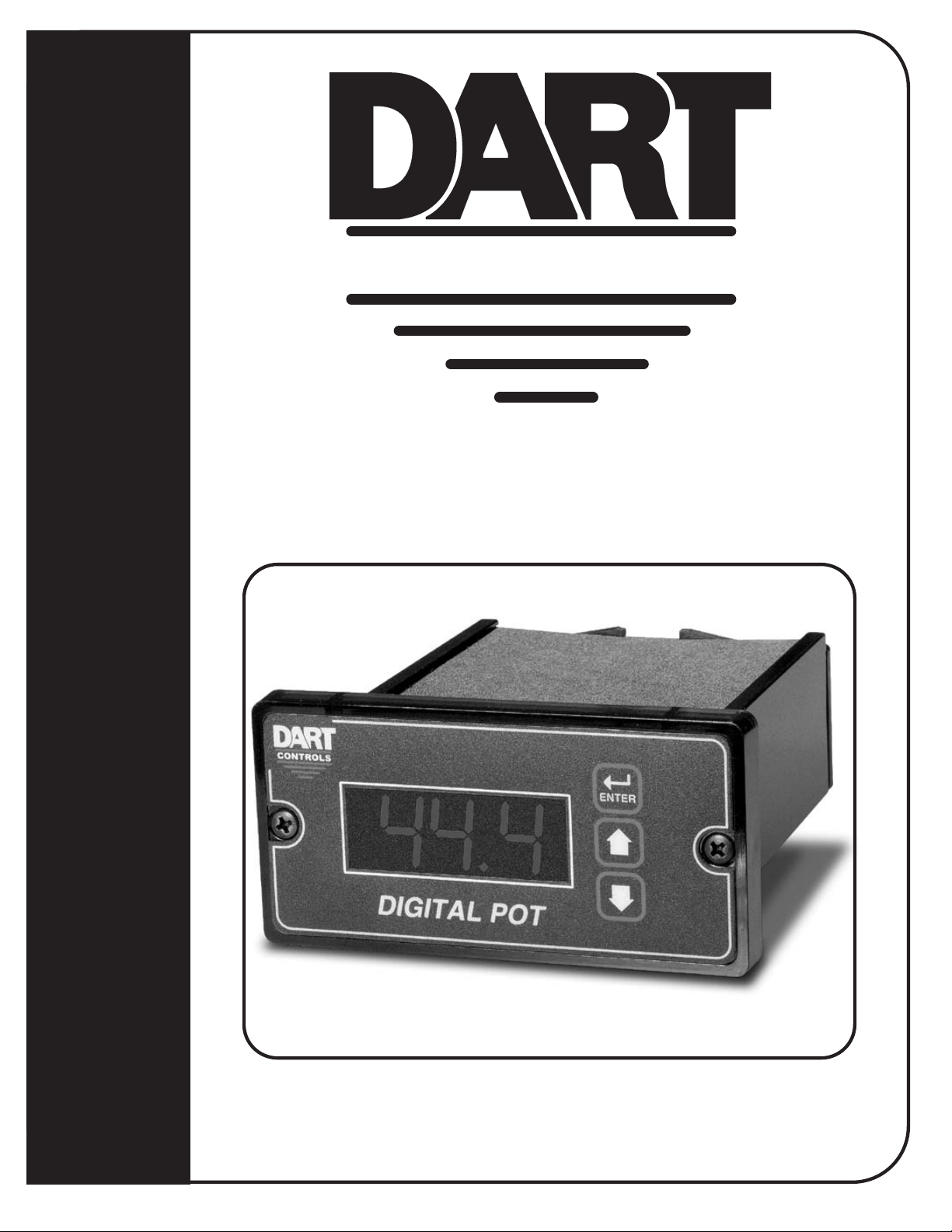
Mechanical Installation
Exploded Panel View
CUSTOMER
MOUNTING PANEL
(HOLE CUT-OUT FOR CONTROL
HOUSING APPROXIMATELY
3.622" WIDE BY 1.770" HIGH)
PANEL MOUNTING GASKET
(WITH THE ADHESIVE SIDE OF
GASKET FACING THE CUSTOMER
MOUNTING PANEL)
DP4
CONTROL
1) GASKET
2) (2) 6-32 X 3/4 PANHEAD BLACK OXIDE STAINLESS SCREWS
3) (2) #6 NUT WITH LOCKWASHER
Cut-out and Mounting Dimensions
4.000"
SUPPLIED WITH EACH CONTROL:
CONTROLS
Ite
Item
Rev
m
MICRO-DRIV
DIGITAL POT
Tac h
ValuPage
Tac
ValPage
Alarm
FwdNeg
ENTER
.140" x 2
5.000"
4.000"
3.622"
DP4
HOUSING DEPTH
4.625"
PA NEL CUT-OUT
0.885"
1.770"
2.289"
1.656"
4.625"
4
Page 7
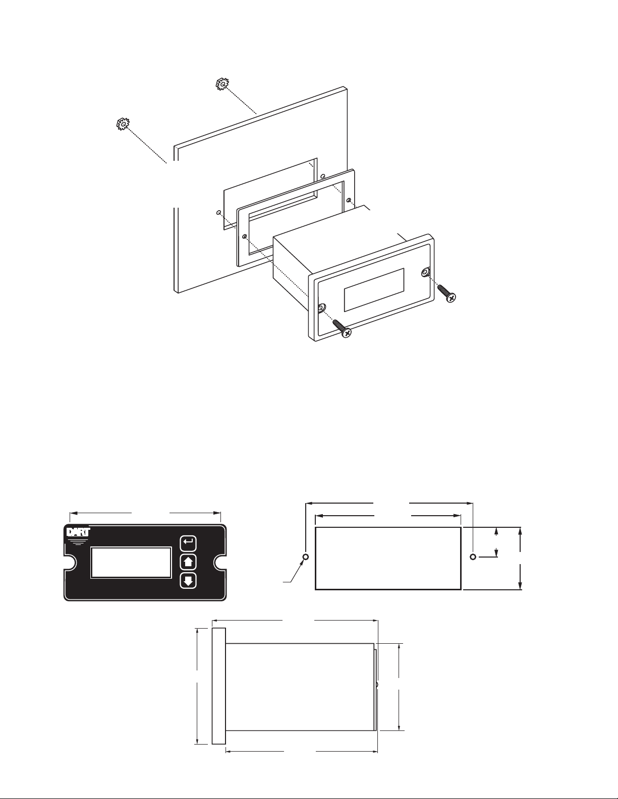
Installation & Diagrams
P1 Terminal Block Hook-Up Diagram
P1-1
P1-2
P1-3
P1-4
DP4
* P1-8 & P1-9 signal inputs may be programmed for a number of functions.
P1-5
P1-6
P1-7
P1-8
P1-9
P1-10
P1-11
P1-12
N
L
HI
W
LO
COM
+5V
S1
S2
NO
C
NC
2 AMP
AC INPUT
AC INPUT
HIGH OUTPUT
WIPER OUTPUT
LOW OUTPUT
COMMON
+5VDC
SIGNAL 1
SIGNAL 2
Alarm Output - Normally Open
Alarm Output - Common
Alarm Output - Normally Closed
*
*
}
85-265VAC
}
Connect to the speedpot
of the control being driven.
High must be positive
}
voltage with respect to low.
External Supply (+5V@50mA)
}
Form C
Relay output
(Programmable)
P1 Terminal Block Descriptions
P1-1 (AC / N) – For single phase AC lines connect the Neutral side of your AC line to this terminal.
For systems with two hot AC lines, connect either of the Hot AC lines to this terminal.
P1-2 (AC / L) – For single phase AC lines connect the Hot side of your AC line to this terminal. For
systems with two hot AC lines, connect either of the Hot AC lines to this terminal.
P1-3 (HI) - This is the POT HI reference terminal. This terminal must be connected to the most positive
speed pot input terminal of the partner control. This terminal will generally be referred to as Pot
HI or +V for positive supplies and Com for negative supplies.
P1-4 (WP) - This is the Wiper output terminal. This terminal will output an analog voltage signal
proportional to the referenced voltage signals connected to P1-3 (HI) and P1-5 (LO). This
terminal should be connected to the wiper or signal input of the partner control.
P1-5 (LO) - This is the POT LO reference terminal. This terminal must be connected to the most
negative speed pot input terminal of the partner control. This terminal will generally be referred
to as Pot LO or Com for positive supplies and –V for negative supplies.
P1-6 (COM) – This is the common point for the control logic. Any other equipment or source needing
to reference the control common will be connected to this terminal.
P1-7 (+5V) – This is a self-contained +5VDC power supply capable of up to 50mA. Various low-
voltage sensors can be driven from this supply if desired.
P1-8 (S1) – This is the programmable signal 1 input. It can be configured to perform a number of
special features including inhibit and jog.
P1-9 (S2) – This is the programmable signal 2 input. It can be configured to perform a number of
special features including inhibit and jog.
P1-10 (1NO) – This is the normally-open contact of the user assignable relay output.
P1-11 (1C) – This is the common contact of the user assignable relay.
P1-12 (1NC) – This is the normally-closed contact of the user assignable relay output.
5
Page 8
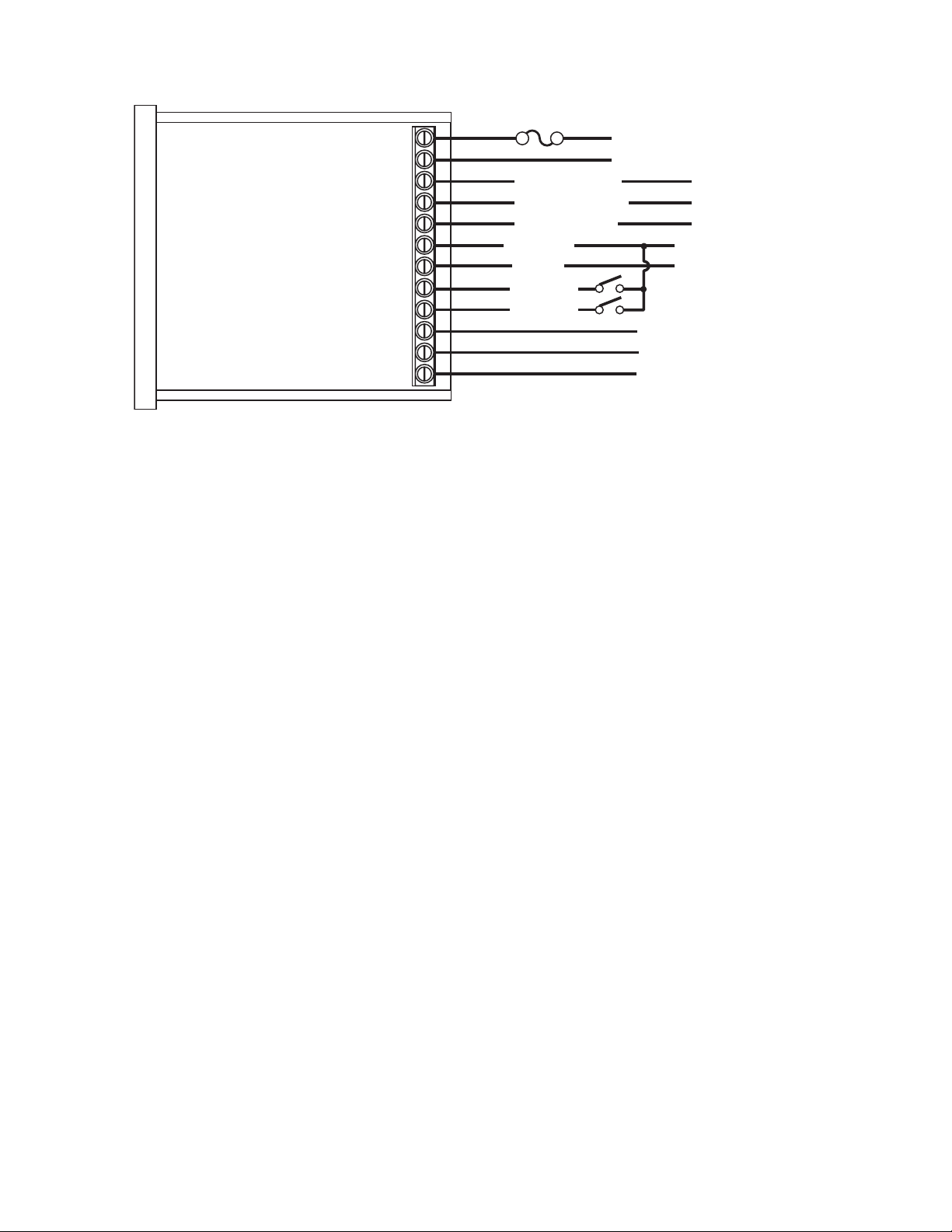
-1 Option Wiring
The -1 option board is a module which allows external up and down push buttons to be wired to the unit.
These buttons operate exactly like the Up and Down buttons on the user interface. This module is
commonly used to allow PLCs or hand-held pendants to operate the front-panel remotely. Wires for the
external buttons are attached via a 3mm European terminal block on the -1 option board. The buttons
are activated by shorting the terminal labeled Com to either the Up or Down terminal.
REMOTE SWITCHING
MICROPROCESSOR
DOWN UP
SERIES PC BOARD
-1 OPTION
BOARD
-3
COMMON
-2
DOWN
-1
UP
Basic Operating Information
The DP4 digital potentiometer is a panel-mount digital-to-analog user interface. Put simply, it allows the
user to adjust the displayed value via push buttons on the front panel; and, outputs a proportional signal
according to its configuration. It can be configured to work with both single and bidirectional partner
drives. It also supports both unipolar and bipolar output supplies.
The DP4 can display values in rate and time formats. In Rate mode, output units such as Gallons-perMinutes, RPM, and Percent are possible with just a few minor adjustments. In Time mode, output units
such as Hours:Minutes (HH:MM), Minutes:Seconds (MM:SS), and Seconds:Ticks (SS:TT) are
supported. In Time modes, the output will be inversely proportional to the displayed value in order to
represent a programmable process time.
See the application examples in this manual for additional information on how the DP4 can be
configured.
Visual Reference
Negative Indicator
Display Window
Reverse Indicator
CONTROLS
Neg
MICRO-DRIV
Ite
Item
Rev
m
Val uPage
ValPage
Fwd
DIGITAL POT
Forward Indicator
Alarm Indicator
Tach
Tac
Alarm
6
ENTER (Select) Button
ENTER
Up & Down Buttons
Page 9

How to Change a Parameter's Value (The Short Story)
1. Hold down the Enter button until Parameter-Selection Mode is entered
2. Using the Up and Down buttons, select the desired parameter number to view or edit
3. Press the Enter button to change the value of the parameter
4. Using the Up and Down buttons, change the parameter's value as desired
5. Press the Enter button to permanently save the changes (Return to Parameter-Selection Mode)
6. Select parameter zero and press the Enter button to return to Running Mode
Operating the User Interface (The Long Story)
Although the DP4 user interface is very versatile, it is also simple to setup and operate. With just a few
button presses, it allows the user to configure a number of adjustable parameters. The LED display has
three basic operating modes: Running Mode, Parameter-Selection Mode, and Value Mode. Each of the
three modes have specific visual indicators that allow the user to immediately determine the current
state or mode of the user interface. Parameter-Selection Mode and Value Mode can only be
entered if the Program Enable jumper is in the “On” position.
Running Mode is the default display of the unit when power is applied. The DP4 will spend the majority
of its time in this mode. In Running Mode, the display shows the target value in the appropriate userdefined format of rate, time, or percentage. The control will continuously attempt to drive the motor at
the requested target rate. In this display mode, the Up and Down buttons increase or decrease the
displayed target value until either the display minimum or display maximum limit is reached. Depending
on the alarm configuration, these buttons may also serve as an alarm-silence or alarm-reset button.
Example displays for rate, time, and follower operating modes are 13.60, 45:30, and 9301.
Parameter-Selection Mode can be entered by simply pressing and holding the Enter button down for
three seconds. Once in Parameter-Selection Mode, the far left of the display will be a ‘P’. The right side
of the display will indicate the currently selected parameter number for editing purposes. Pressing the
Up or Down button will increase or decrease the selected parameter number on the display. Although
the parameter numbers are in numerical order, some numbers are skipped. These numbers represent
reserved parameters that are not yet implemented and are not displayed. Once the desired parameter
number is displayed, a press of the Enter button will change the display to the Value Mode. When in
Parameter-Selection Mode, pressing the Enter button with parameter 0 selected will cause the
unit to return to Running Mode. Example displays for Parameter-Selection Mode are P 1, P 12, and
P 54. See the Software Parameters for a list of available parameters.
Value Mode is used to modify the value of the selected parameter. When in Value Mode, the two dots
which form the colon, between digits two and three, will alternately flash (one, then the other) to inform
the user that a parameter’s value is being edited. Pressing the Up or Down button increases or
decreases the selected parameter’s value. See the Software Parameters for a list of allowable values
and ranges. Value changes take effect immediately. For example, when scrolling through the alarm
output conditions, the relay will activate as the always-active selection is passed. Once the desired
value is showing in the display window, pressing the Enter button again will return to ParameterSelection Mode. The new value is not saved in permanent memory until the Enter button is pressed.
Removing power from the unit while in Value Mode may result in the specified new value being lost.
7
Page 10

Detailed Configuration Instructions
Default Configuration
When shipped from the factory, the following basic settings are in place:
Rate Mode Operation in % Units
Unipolar Output without Deadband
Decimal Point Display: XXX.X
Display Range: 0 - 100.0
Output Range: 0 - 100% of Applied Pot High Voltage
Signal Input 1 (S1) Mode: Force Output to 0% when Low
Signal Input 2 (S2) Mode: Force Output to 0% when Low
Alarm Output: Disabled
Resetting the Unit to Factory Defaults
The factory-default settings can be easily restored using either of two methods. Both methods require
the Program Enable jumper to be in the “On” position. The first is to apply power to the unit with both
the Enter and Down buttons pressed for 3 seconds. The second is to change the value of parameter
95 to 5.
JP1 (Program Enable Jumper)
The JP1 jumper is located under the dust cover on the back end of the upper board. When the jumper
is set to the "Off" position, all programming features are locked out to the front panel user. When the
jumper is in the "On" position, the programming parameters are open to change. JP1 is shipped from
the factory set in the "On" position.
8
Page 11

Software Parameters
Parameter
0 Selecting this item exits to Running Mode n/a n/a
Read-Only Parameters
1 Model Number 40 – DP4 Unit 40
2 Software Build 1 – 9999 n/a
3 Hardware Version 1 – 9999 n/a
4 Serial Number – Major (reserved) n/a n/a
5 Serial Number – Minor (reserved) n/a n/a
10 Operating Mode Rate Mo d es:
11 Display Intensity 0 – 31 (Dim – Bright) 26
12 Display Zero Blank ing 1 – ___X Show at least 1 Di git
13 Decimal Point Position 0 – DP Disabled (XXXX)
15 Keypad M ode 1 – Linear, Constant R ate
16 Keypad Scroll Delay 0 – 30 (Fast – Slow) 10
18 Power -up Mode 1 – Default to Zero Display
19 Power-up Value 0 – 9999 (Display Units) 0
20 Dis play Valu e at Mi nimum Output -9999 – 99 99 (Display Units) 0
21 Display Val u e at Ma ximum Output -9999 – 9999 (Dis play Units) 1000
22 Dis play Valu e at Center Out pu t (B ipolar Onl y ) -9999 – 9999 (Dis play Units ) 0
25 Output % - Minimum 0 – 10 00 (1/10th Percent Units) 0
26 Output % - Maximum 0 – 1000 (1/1 0th Percent Units) 1000
27 Out p ut % - Center (B ipolar Modes Only) 0 – 1000 (1/10th Pe rc e nt Units) 500
28 Output Deadband Width 0 – 1000 (1/10th Percent Units) 0
General Setup
Display & Output Setup
Description
Value Range
(units)
1 – Unipolar Output
2 – Unipolar Output with Deadband
3 – Bipolar O utput
4 – Bipolar Output with Deadband
Time Modes:
5 – Unipolar Output
6 – Unipolar Output with Deadband
7 – Bipolar O utput
8 – Bipolar Output with Deadband
Other Modes:
9 – Absolute Value Output with Relay
Direc tion Cont r ol
10 – Abso lute Valu e Ou t p ut wi th
Relay D ir ect. Control an d De adband
2 – __XX Show at least 2 Digits
3 – _XXX Show at least 3 Digits
4 – XXXX Show all 4 Digits
1 – X.XXX
2 – XX.XX
3 – XXX.X
4 – XXXX.
2 – Non-linear, Accelerating R ate
2 – Default to Power-up Value
3 – Default to Previous Running Val.
Factory
Default
1
2
3
2
3
User
Settings
9
Page 12

Software Parameters, cont'd
Parameter
Signal Input #1 (S1) Setup
30 S1 Input Configuration 1 – Output 0% When S1 Low
31 S1 Setpoin t -9999 – 9999 (Dis play Units ) 0
Signal Input #2 (S2) Setup
35 S2 Input Configuration 1 – Output 0% When S2 Low
36 S2 Setpoin t -9999 – 9999 (Dis play Units ) 0
40 Activation Conditi ons 0 – Alway s Off
41 Output Style & Reset Mode 1 – Constant & Auto Reset
42 Reset Configuration 1 – No Sil., Reset on Key
43 Display Flash On Active Alarm 0 – Alarm Flash Disabled
44 Pulse on Time 1 – 3600 (seconds) 1
45 Pulse off Time 1 – 3600 (seconds) 1
46 Pulse Count 0 – 9999 (pulses) 0
47 Lower Limit 0 – 9999 (display units) 0
48 Upper Limit 0 – 9999 (display units) 9999
95 Restore Settings to Factory Default 0 – Do Nothing & Exit
98 Save to User Default Area 0 – Do Nothing & Exit
99 Restore from User Default Area 0 – Do Nothing & Exit
Alarm Output Configuration
Parameter Memory Commands
Description
Value Range
(units)
2 – Output 0% When S1 High
3 – Output Setpoint When S1 Low
4 – Output Setpoint When S1 High
5 – Output 100% When S1 Low
6 – Output 100% When S1 High
2 – Output 0% When S2 High
3 – Output Setpoint When S2 Low
4 – Output Setpoint When S2 High
5 – Output 100% When S2 Low
6 – Output 100% When S2 High
1 – Always On
2 – Active when Above upper limit
3 – Active when Below lower limit
4 – Active in side Rang e
5 – Active outside Range
6 – Active Zero or Equivalent Output
7 – Relay Di r ection Control Mode
2 – Constant & Manual Reset
3 – Pulsed & Auto Reset
4 – Pulsed & Manual Reset
2 – No Sil., Reset on S2 High
3 – No Sil., Reset on S2 Low
4 – Sil., Reset on Key
5 – Sil., Reset on S2 High
6 – Sil., Reset on S2 Low
1 – Alarm Flash Enabled
5 – Restore Factory Defaults
5 – Save Setting
1 – Restore Settings
Factory
Default
1
1
0
1
1
0
0
0
0
User
Settings
10
Page 13

Parameter Descriptions
Parameter 0 – Exit to Running Mode
When parameter 0 is selected in Parameter-Selection Mode, the unit will return to Running Mode
and display the running value. This should be selected once the changes to the parameters are
completed.
Parameter 1 – Model Number (Read Only)
This is a number which represents the base model number for the product. The model code for
the DP4 is 40.
Parameter 2 – Software Build (Read Only)
The software build is a code which identifies the software version of the unit.
Parameter 3 – Hardware Version (Read Only)
The hardware version is a code which identifies which hardware was used to build the unit.
Parameter 4 & 5 – Serial Number, Major & Minor (Read Only)
These parameters are reserved for future use as an electronic serial number and are unique
to each manufactured unit.
Parameter 10 – Operating Mode
This parameter defines the operating mode for the entire unit. There are two basic modes of
operation, Rate and Time. In Rate modes, the unit displays in rate and non-time-based units
such as RPM, Gallons per Hour, and Percent of Maximum Output. In Time modes, the unit
displays in time-based units using the format AA:BB. The AA:BB format can be adjusted to
represent Hours:Minutes or Minutes:Seconds.
Mode 1 – Rate Mode, Unipolar Output
Mode 2 – Rate Mode, Unipolar Output with Deadband
Mode 3 – Rate Mode, Bipolar Output
Mode 4 – Rate Mode, Bipolar Output with Deadband
Mode 5 – Time Mode, Unipolar Output
Mode 6 – Time Mode, Unipolar Output with Deadband
Mode 7 – Time Mode, Bipolar Output
Mode 8 – Time Mode, Bipolar Output with Deadband
Mode 9 – Other Mode, Absolute Value Output with Relay Direction Control
This mode allows the DP4 to interface with bi-directional Controls that have FWD and REV
command inputs and use the absolute value of the pot to determine speed only. In this
mode, the user must configure the following parameter:
Display Min, Max, and Center
Output Min and Max
Output Deadband (Mode 10 Only!)
Mode 10 – Other Mode, Absolute Value Output with Relay Direction Control and with
Deadband Funcion
Same as Mode 9, except deadband is supported. Must set Deadband value at Item 28.
Parameter 11 – Display Intensity
This parameter adjusts the intensity of the LED display digits in the front panel of the unit. The
values of 0 – 31 correspond to a gradual change from very dim to very bright. This is often useful
when the DP4 is used in the same panel as other pieces of equipment with LED display and a
uniform display brightness is desired. Simply adjust the DP4 to match its surroundings.
Parameter 12 – Display Zero Blanking
This selects the number of display digits that are required to be displayed regardless of the
display value. For example, with a Display Zero Blanking setting of 3 and a displayed value of
6, the display would show "_006".
Mode 1: ___X Always show at least 1 digit
Mode 2: __XXAlways show at least 2 digits
Mode 3: _XXX Always show at least 3 digits
Mode 4: XXXX Always show all 4 digits
11
Page 14

Parameter 13 – Decimal Point (DP) Position
This selects the format of the display with respect to the decimal point’s position. This parameter does
not affect the value entry for other parameters. The decimal point is only displayed in Rate modes.
For example, if the user desires to display numbers such as 12.34 or 1.05, then parameter 13 should
be set to 2.
Mode 0: Fixed XXXX (DP disabled)
Mode 1: Fixed X.XXX
Mode 2: Fixed XX.XX
Mode 3: Fixed XXX.X
Mode 4: Fixed XXXX.
Parameter 15 – Keypad Mode
This parameter selects the operating mode of the front-panel push buttons. In some applications,
increasing or decreasing the scroll rate provides the user more controllability when entering settings.
Parameters 14 and 15 affect only the Up and Down buttons when the user interface is in Running
Mode. These settings also apply to remote Up / Down buttons which are attached via the -1 option
board.
Mode 1: Linear, Constant Rate
In linear mode, pressing and holding the Up or Down buttons will cause the display to
continuously change value in the requested direction until either the Display Minimum or Display
Maximum is reached. The displayed value will scroll at a constant rate which is specified using
parameter 15.
Mode 2: Non-linear, Accelerating Rate
In non-linear mode, pressing and holding the Up or Down buttons will cause the display to
continuously change value in the requested direction until either the Display Minimum or Display
Maximum is reached. The displayed value will initially scroll at a slow rate and increase in speed
until the maximum scroll rate is achieved. The initial scroll rate is specified using parameter 15.
Parameter 16 – Keypad Scroll Mode
This parameter sets the scroll speed for the front-panel push buttons. The function of this parameter
varies slightly depending on the Keypad Mode. See parameter 14 for more details.
Parameter 18 – Power-Up Mode
This parameter defines the mode which determines the default Running Value when power is initially
applied to the DP4.
Mode 1: Default to Zero
When in this mode, the unit will default to zero (display units).
Mode 2: Default to Power-Up Value
When in this mode, the unit will default to the Power-up Value, parameter 19.
Mode 3: Default to Previously Running Value
When in this mode, the unit will default to the previous running value before power was removed.
A previous running value must have been active for at least 3 seconds to be recalled after power
has been disconnected and reapplied.
Parameter 19 – Power-Up Value
When Power-up Mode is set to 2, this parameter will designate the default display value at power-up
in display units.
Parameter 20 – Display Value at Minimum Output
This parameter defines the lower end of the display range. This is the value which limits how low the
user is able to scroll the displayed value in Running Mode. In Rate and Time modes, this value is set
in display units. This parameter is set without consideration for the decimal point's position. For
example, setting this parameter to 125 would set the lower display limit at 12.5, 0.125, or 125 seconds
according to the other configuration parameters.
Parameter 21 – Display Value at Maximum Output
This parameter defines the upper end of the display range. This is the value which limits how high the
user is able to scroll the displayed value in Running Mode. In Rate and Time modes, this value is set
in display units. This parameter is set without consideration for the decimal point's position. For
example, setting this parameter to 1000 would set the upper display limit at 100.0, 1.000, or 1000
seconds according to the other configuration parameters.
12
Page 15

Parameter 22 – Display Value at Center Output
This defines the center value for the display in bipolar (or bidirectional) modes of operation. In
bipolar applications, this value should be set to the display value that corresponds to a null or
zero output. When in Running Mode, display values above this will produce an output toward
the programmed Maximum Output %; whereas, display values below this will produce an output
toward the programmed Minimum Output %. As the display value approaches the number
programmed in this parameter, the DP4 will produce an output that approaches the percentage
programmed in parameter 28. See parameters 25 - 27 and the application examples for
additional information.
Parameter 25 – Minimum Output % (in 1/10 percent units)
This parameter sets the output percentage which corresponds to the minimum display value,
parameter 20. This parameter has a range of 0 to 1000 which represents 0.0 to +100.0 percent
of output. When the user is adjusting the display value towards the programmed minimum
display, the output will linearly approach the value of this parameter. For example, setting this
parameter to 25 will configure the DP4 to output 2.5% when the user adjusts the display value
to equal the display minimum, parameter 20. Setting this minimum percentage higher than the
maximum (parameter 26) will cause the polarity of the output to be inverted. See parameters
20 - 22 and the application examples for additional information.
Parameter 26 – Maximum Output % (in 1/10 percent units)
This parameter sets the output percentage which corresponds to the maximum display value,
parameter 21. This parameter has a range of 0 to 1000 which represents 0.0 to +100.0 percent
of output. When the user is adjusting the display value towards the programmed maximum
display, the output will linearly approach the value of this parameter. For example, setting this
parameter to 850 will configure the DP4 to output 85.0% when the user adjusts the display value
to equal the display maximum, parameter 21. Setting this maximum percentage higher than the
minimum (parameter 25) will cause the polarity of the output to be inverted. See parameters 20
- 22 and the application examples for additional information.
Parameter 27 – Center Output % (in 1/10 percent units)
This defines the center percentage for the output in bipolar (or bidirectional) modes of operation.
In bipolar applications, this value should be set to the percentage of output that corresponds to
a null or zero output of the partner drive. When in Running Mode, display values above the
display center (parameter 22) will produce an output toward the programmed Maximum Output
%; whereas, display values below the display center (parameter 22) will produce an output
toward the programmed Minimum Output %. As the display value approaches the programmed
display center value (parameter 22), the DP4 will produce an output that approaches the
percentage programmed in this parameter. See parameters 20 - 22 and the application
examples for additional information.
Parameter 28 – Output Deadband % (in 1/10 percent units)
This defines the width of the output's deadband. This is the range of output percentage values
which will produce a zero or center output percentage in unipolar and bipolar modes respectively.
This value is the width of the range in percentage units. For example: If the DP4 were configured
for bipolar operation and this parameter were set to 50, then any output which was within 5% of
the center output percentage would be forced to the center output value. See parameters 20 22 and the application examples for additional information.
Parameter 30 – Signal Input 1 (S1) Configuration
This parameter determines the operating mode of signal input 1 (S1).
Mode 1: Output 0% When S1 Low
When the S1 input is at an electrically low state or wired to the unit's common, the DP4 will
force its output to 0%. Once the S1 input returns to an electrically high (+5V) state or
allowed to float disconnected, the output will once again correspond to the display value.
Mode 2: Output 0% When S1 High
When the S1 input is at an electrically high (+5V) state or allowed to float disconnected,
the DP4 will force its output to 0%. Once the S1 input returns to an electrically low state
or wired to the unit's common, the output will once again correspond to the display value.
13
Page 16

Mode 3: Ouput Setpoint When S1 Low
When the S1 input is at an electrically low state or wired to the unit's common, the DP4 will
force its output to a percentage which corresponds to the programmed jog setpoint,
parameter 31. Once the S1 input returns to an electrically high (+5V) state or allowed to
float disconnected, the output will once again correspond to the display value.
Mode 4: Output Setpoint When S1 High
When the S1 input is at an electrically high (+5V) state or allowed to float disconnected,
the DP4 will force its output to a percentage which corresponds to the programmed jog
setpoint, parameter 31. Once the S1 input returns to an electrically low state or wired to
the unit's common, the output will once again correspond to the display value.
Mode 5: Output 100% When S1 Low
When the S1 input is at an electrically low state or wired to the unit's common, the DP4 will
force its output to 100%. Once the S1 input returns to an electrically high (+5V) state or
allowed to float disconnected, the output will once again correspond to the display value.
Mode 6: Output 100% When S1 High
When the S1 input is at an electrically high (+5V) state or allowed to float disconnected,
the DP4 will force its output to 100%. Once the S1 input returns to an electrically low state
or wired to the unit's common, the output will once again correspond to the display value.
Parameter 31 – Signal Input 1 (S1) Setpoint
When the S1 configuration, parameter 30, is set to one of the setpoint (jog) modes(modes 3 or
4), this parameter defines the jog setpoint in display units. This parameter is always set in
display units.
Parameter 35 – Signal Input 2 (S2) Configuration
This parameter determines the operating mode of signal input 2 (S2).
Mode 1: Output 0% When S2 Low
When the S2 input is at an electrically low state or wired to the unit's common, the DP4 will
force its output to 0%. Once the S2 input returns to an electrically high (+5V) state or
allowed to float disconnected, the output will once again correspond to the display value.
Mode 2: Output 0% When S2 High
When the S2 input is at an electrically high (+5V) state or allowed to float disconnected,
the DP4 will force its output to 0%. Once the S2 input returns to an electrically low state
or wired to the unit's common, the output will once again correspond to the display value.
Mode 3: Ouput Setpoint When S2 Low
When the S2 input is at an electrically low state or wired to the unit's common, the DP4 will
force its output to a percentage which corresponds to the programmed jog setpoint,
parameter 36. Once the S2 input returns to an electrically high (+5V) state or allowed to
float disconnected, the output will once again correspond to the display value.
Mode 4: Output Setpoint When S2 High
When the S2 input is at an electrically high (+5V) state or allowed to float disconnected,
the DP4 will force its output to a percentage which corresponds to the programmed jog
setpoint, parameter 36. Once the S2 input returns to an electrically low state or wired to
the unit's common, the output will once again correspond to the display value.
Mode 5: Output 100% When S2 Low
When the S2 input is at an electrically low state or wired to the unit's common, the DP4 will
force its output to 100%. Once the S2 input returns to an electrically high (+5V) state or
allowed to float disconnected, the output will once again correspond to the display value.
Mode 6: Output 100% When S2 High
When the S2 input is at an electrically high (+5V) state or allowed to float disconnected,
the DP4 will force its output to 100%. Once the S2 input returns to an electrically low state
or wired to the unit's common, the output will once again correspond to the display value.
Parameter 36 – Signal Input 2 (S2) Setpoint
When the S2 configuration, parameter 35, is set to one of the setpoint (jog) modes(modes 3 or
4), this parameter defines the jog setpoint in display units. This parameter is always set in
display units.
14
Page 17

Parameter 40 – Alarm 1 Conditions
This defines which conditions will result in the alarm 1 output being activated.
Mode 0: Always Inactive
The alarm output will remain in an inactive state. In this state, the NC and C contacts will
be internally electrically connected.
Mode 1: Always Active (When Power Is Applied)
The alarm output will become active when the power is applied to the unit. In this state,
the NO and C contacts will be internally electrically connected.
Mode 2: Active When Display Value Above Limit
The alarm output will activate when the displayed value is above the upper limit setting,
parameter 48.
Mode 3: Active When Display Value Below Limit
The alarm output will activate when the displayed value is below the lower limit setting,
parameter 47.
Mode 4: Active When Display Value Inside Range
The alarm output will activate when the displayed value is greater than or equal to lower
limit settings and less than or equal to the upper limit setting.
Mode 5: Active When Display Value Outside Range
The alarm output will activate when the displayed value is less than the lower limit setting
or greater than upper limit setting.
Mode 6: Active When Display Value Results in a Zero or Equivalent Output
If the display is set to a value that produces a zero output or is within the programmed
deadband, then the alarm is activated.
Mode 7: Relay Direction Control Mode
In this mode, the relay output will determine which direction is being requested. This will
typically be used with Item 10 modes 9 & 10.
Forward = relay not energized; Reverse = relay energized
Parameter 41 – Alarm 1 Output Style & Reset Configuration
This setting configures the output mode and reset method for the alarm output.
Mode 1: Constant & Auto Reset
In this mode, the alarm output will remain active until the alarm condition ceases to exist.
The alarm will automatically reset when the conditions return to normal.
Mode 2: Constant & Manual Reset
In this mode, the alarm output will remain active until the alarm is reset manually. See
parameter 42 for details.
Mode 3: Pulse & Auto Reset
In this mode, the alarm output will pulse on and off until the alarm condition ceases to exist.
The pulsed modes are commonly used for audible alarms where a constant output would
be considered distracting or awkward. The alarm will automatically reset when the
conditions return to normal.
Mode 4: Pulse & Manual Reset
In this mode, the alarm output will pulse on and off until the alarm is reset manually. See
parameter 42 for reset details. The pulsed modes are commonly used for audible alarms
where a constant output would be considered distracting or awkward.
Parameter 42 – Alarm 1 Reset Configuration
This setting determines which actions will cause an active alarm to be silenced or reset.
Mode 1: No Silencing, Reset On Any Button Press
In this mode, an active alarm cannot be silenced. Once the alarm condition ceases to
exist, however, any user-interface button may be pressed to cause a manual reset.
Mode 2: No Silencing, Reset On S2 Input High (Not Wired To Common)
Similar to Mode 1. Once the alarm condition ceases to exist, setting the S2 input to a high
(+5V) state or allowing it to float disconnected will cause a manual reset.
15
Page 18

Mode 3: No Silencing, Reset On S2 Input Low (Wired To Common)
Similar to Mode 1. Once the alarm condition ceases to exist, setting the S2 input to a low
(COM) state or wiring it to common will cause a manual reset.
Mode 4: Silencing Enabled, Reset On Any Button Press
When the conditions for an active alarm persist, pressing any user-interface button will
result in the alarm being silenced or deactivated, but not reset. A second attempt to reset
the alarm must be made after the condition cease to exist to clear the alarm.
Mode 5: Silencing Enabled, Reset On S2 Input High (Not Wired To Common)
Similar to Mode 4. Setting the S2 input to a high (+5V) state or allowing it to float
disconnected will cause the alarm to be silenced or reset depending on the current state
of the alarm conditions.
Mode 6: Silencing Enabled, Reset On S2 Input Low (Wired To Common)
Similar to Mode 4. Setting the S2 input to a low (COM) state or wiring it to common will
cause the alarm to be silenced or reset depending on the current state of the alarm
conditions.
Parameter 43 – Alarm 1 Display Flash On Alarm
This will cause the display to flash when an alarm condition is active.
Parameter 44 – Alarm 1 Pulse on Time
This parameter defines the number of seconds the output should be enabled during the ‘on’
phase of an active pulsing alarm’s output.
Parameter 45 – Alarm 1 Pulse off Time
This parameter defines the number of seconds the output should be disabled during the ‘off’
phase of an active pulsing alarm’s output.
Parameter 46 – Alarm 1 Pulse Count
This setting determines how many pulses are output when the alarm is activated and is
configured in pulse output style.
When 0 is entered, the unit will be set for continuous pulses
while the alarm is active.
Parameter 47 – Alarm 1 Lower Limit
This setting defines either the lower limit or lower end of a range for the alarm region. Alarm limits
are set in display units without regard to decimal point or colon position. In Rate Modes, a limit
of 123 could represent a display value of 123, 12.3, 1.23, or 0.123. When in Time Mode, a limit
of 123 would represent 1:23 on the display.
Parameter 48 – Alarm 1 Upper Limit
This setting defines either the upper limit or upper end of a range for the alarm region. Alarm limits
are set in display units without regard to decimal point or colon position. In Rate Mode, a limit
of 123 could represent a display value of 123, 12.3, 1.23, or 0.123. When in Time Mode, a limit
of 123 would represent 1:23 on the display.
Parameter 95 – Factory Default Command
When set to a value of 5, the unit will be reset to factory default settings. This can also be
achieved by applying power to the unit with both the Enter and Down buttons depressed.
programming jumper must be in the "On" position for this method to function.
Parameter 98 – Save to User Default Area Command
When set to a value of 5, the unit will store all adjustable parameters to the user default area. The
user default area is intended to be a location where an OEM or integrator can store settings
specific to their application. Using this, an OEM can easily refresh their custom settings in the
field if an end-user accidentally reconfigures the unit unsuccessfully. Another common use for
this area is testing and initial setup. The user can store known-good settings here and easily
experiment without the fear of losing the optimal configuration.
Parameter 99 – Restore from User Default Area Command
When set to a value of 1, the unit will restore all adjustable parameters from the user default area.
See parameter 98 for additional information.
The
16
Page 19

User Interface for Industrial Conveyor Oven with AC Drive
Description:
An industrial tunnel oven currently uses an AC invertor drive with an attached speedpot to
control the motor which drives its train. Because the process time for the oven is known, it is
preferred that the user be able to set the process time in minutes and seconds on a digital display.
Using a DP4, this is quite simple and requires a minimum amount of installation and training effort
to complete. In this example, a DP4 has been connected to the existing AC invertor drive and
a remote speed select switch which allows the user to select from one of two preprogrammed
time settings (2 or 4 minutes) or to enter a manual mode where the display of the unit can be
directly adjusted using the front panel’s up and down arrow buttons. The desired display range
is from 90 seconds (1:30) to 600 seconds (10:00). Calibration and measurement from the
previously installed speed potentiometer has shown that a voltage output of 30% - 76% of the
applied reference voltage from the AC invertor will produce the desired time range.
Application Diagram:
Application Examples
Oven Speed Select Switch
SPEED 1 SPEED 2
MANUAL
AB
Heat Source
Tunnel Oven
CONTROLS
Tach
Ite
ValuPage
Alarm
FwdNeg
Rev
m
ENTER
6:30
DIGITAL POT
Dart DP4
Contol
Connect to
Coupling
Partner
Motor
Controller
Variable-Frequency
AC Control
Coupling to
Chain Drive
AC Gear Motor
Drive Train Specs:
1380 RPM at non-reduced
motor shaft equates to
6 minutes and 40 seconds
of tunnel time
17
Page 20

Wiring Diagram:
N
L
HI
W
LO
COM
+5V
S1
S2
NO
C
NC
*FUSE
+10V Ref.
Input
-10V Ref.
NOT USED
NOT USED
}
DP4
P1-1
P1-2
P1-3
P1-4
P1-5
P1-6
P1-7
P1-8
P1-9
P1-10
P1-11
P1-12
* Size fuse according to unit and application. See
electrical specifications for maximums.
Parameter Configuration:
Parameter Value Notes
10 5
20 90
21 600
25 30
26 76
30 3
31 120
35 3
36 240
Output mode set to time unipolar to support single-direction application
Display minimum set to 90 seconds (1 minut e 30 secon ds )
Display maximum set to 600 seconds (10 minutes)
Set output minimu m to 3 0 %
Set output maximu m to 7 6 %
Input S1 set to force jog w h en low
Input S1 jog setpoint set to 120 seconds (2:00 on the display)
Input S2 set to force jog w h en low
Input S2 jog setpoint set to 240 seconds (4:00 on the display)
VariableFrequency
AC
Control
Speed 1
Speed 2
AC Line 85-265VAC, 50-60 Hz
}
Partner
Motor
Control
Manual
Speed Selector Switch
(3-Position)
Digital Front Panel for Regenerative Industrial Treadmill
Description:
A bidirectional industrial treadmill with a speed range of +/- 12 mph is currently powered by an
analog regenerative control using an external speedpot to adjust the speed. Unfortunately, the
speed pot does not offer enough accuracy and repeatability to allow for proper operation of the
treadmill. A DP4 has been added to the system to give it a quick and easy to use digital front
panel. The DP4 has also been wired to support an external jog switch for rapidly (and
temporarily) setting the belt speed to a predetermined value of 5 mph. An enable switch allows
the user to immediately force the regen to a stopped conditional should it be necessary. For
safety reasons, the unit will default to zero output when power is initially applied.
18
Page 21

Application Diagram:
Treadmill
Belt
Analog
Regenerative
Control
DC
Motor
Wiring Diagram:
DP4
Enable Switch
Enable
P1-1
P1-2
P1-3
P1-4
P1-5
P1-6
P1-7
P1-8
P1-9
P1-10
P1-11
P1-12
Disable
N
L
HI
W
LO
COM
+5V
S1
S2
NO
C
NC
CONTROLS
+10V Ref.
-10V Ref.
NOT USED
}
Tach
Ite
ValuPage
Alarm
Rev
FwdNeg
m
12.4
DIGITAL POT
Dart DP4
Control
*FUSE
Analog
Input
Enable Switch
NOT USED
Regenerative
Drive
Jog Switch
Jog
ENTER
AC Line 85-265VAC, 50-60 Hz
}
Partner
Control
Jog Switch
Run
* Size fuse according to unit and application. See
electrical specifications for maximums.
19
Page 22

Parameter Configuration:
Parameter Value Notes
10 3
12 2
13 3
18 1
20 120
21 120
22 0
25 0
26 1000
27 500
35 3
36 50
Output mode set to rate bipolar to support +/-10V regenerative drive
Zero-blanking set to 2 digits
Decimal point position set to XXX.X on display
Power- up display value set to d efault at 0.0
Display minimu m se t to -1 2 .0
Display maxi mu m set to 12.0
Display center set to 0.0
Set output minimum to 0% (-10V)
Set output maximum to 100% (+10V)
Set output center to 50% (0V)
Input S2 set to force j og when low
Input S2 jog setpoint set to 5.0
Programmable Digital Voltage Source with Enable Switch
Description:
A test stand needs an easily adjustable and accurate 0 - 5VDC signal to test the response of
a device under test. The digital display of the voltage source (DP4) should read in 1/100ths of
a volt (V.VV). When the unit initially has power applied, it should always default to an output
voltage of zero volts. When the output is greater than 0 volts, an illuminated alarm should light
and flash to indicate that the device under test is being actuated.
Application Diagram:
Enable Switch
Enable
Disable
D.U.T.
0-5V
Programmable
Output
CONTROLS
ItemValuPage
Rev
3.25
DIGITAL POT
Dart DP4
Device
Under
Test
Tach
Alarm
FwdNeg
ENTER
Pylon-Style
Illuminated
Alarm
20
Page 23

Wiring Diagram:
N
L
HI
W
LO
COM
+5V
S1
S2
NO
C
NC
*FUSE
Enable Switch
NOT USED
NOT USED
DP4
P1-1
P1-2
P1-3
P1-4
P1-5
P1-6
P1-7
P1-8
P1-9
P1-10
P1-11
P1-12
* Size fuse according to unit and application. See
electrical specifications for maximums.
Parameter Configuration:
Parameter Value Notes
12 3
13 2
18 1
20 0
21 500
25 0
26 1000
40 2
41 3
48 0
Zero-blanking set to 3 digits
Decimal point position set to XX.XX on display
Power-up dis play value set to default at 0.00
Display minimum se t to 0 . 0 0
Display maximu m set to 5. 0 0
Set output minimum to 0% (0V)
Set output maximum to 100% (5V)
Alarm output ac tive when above upper limit
Alarm output s et to puls e and au to-reset
Alarm upper limit set to activate above valu e of 0
AC Line Input 85-265VAC, 50-60 Hz
}
0-5V Output Voltage
to Device Under Test
120VAC
Illuminated
Pylon-Style
Alarm
21
Page 24

Troubleshooting
Problem Possible Case Solution
Display is blank Power not applied
Using a volt meter, verify that a voltage between 85 and 265VAC is measured between
the L and N terminal block positions.
Defective unit
Display is dim Display intensity
When power is
applied, “LF-L” is
displayed
When power is
applied, “LF-H” is
displayed
The alarm output
does not seem to
function
parameter is too low
AC line supplying
power to unit has too
much noise
AC line supplying
power to unit has an
abnormally low
frequency
AC line supplying
power to unit has too
much noise
AC line supplying
power to unit has an
abnormally high
frequency
Alarm output
parameters not
configured properly
Contact technical support for additional help and instructions.
Editing and increasing the display intensity parameter should cause the display digits to
become brighter.
Review routing of power wires in machine to minimize electrical noise. Look for other
devices which share the same circuit which may be producing unacceptable levels of
line noise. In some applications, such as welding equipment, a careful regiment of
applying an AC line filter, re-routine wires, dividing circuits, using shielded cable, and
properly grounding devices will usually solve the problem.
The unit is designed to operate with AC lines from 48-62 Hertz (cycles per second).
This is typically not a problem because the international standards are 50 and 60 Hertz.
Alarm output parameters not configured properly
Review alarm output parameters. The alarm relay output can be tested by selecting
the “Always On” value for the Activation Condition parameters for the alarm output.
When doing this, the relay click should be audible and the NC (Normally Closed) and C
(Common) terminals should become internally shorted at the terminal block.
Technical Support Options
• Visit the Dart Controls Web Site at:
• Email technical support at:
techsupport@dartcontrols.com
• Telephone technical support at 317-733-2133 ext. 4
www.dartcontrols.com
What's Special About www.dartcontrols.com?
• Changes to printed material and product offerings first appear online
• Product manuals and other literature are easily accessible
• All information can be easily displayed or printed as needed
22
Page 25

- Notes -
23
Page 26

- Notes -
24
Page 27

- Notes -
25
Page 28

REPAIR PROCEDURE
Re-Order from
omegamation.com
Omegamation
TM
1-888-55-OMEGA
1-888-55-66342
1-888-55-66342
In the event that a Product manufactured by Dart Controls Incorporated (DCI) is in need of
repair service, it should be shipped, freight paid, to: Dart Controls, Inc., 5000 W. 106th Street,
Zionsville, IN. 46077, ATTN: Repair Department.
Those orders received from anyone without and existing account with DCI will need to specify
if they will be paying COD or Credit Card (Master Card or Visa). This information is required
before work can begin. If you have an account with Dart your order will be processed according
to the terms listed on your account.
Completed repairs are returned with a Repair Report that states the problem with the control
and the possible cause. Repair orders are returned via UPS Ground unless other arrangements
are made. If you have further questions regarding repair procedures, contact your Dart Controls,
Inc. at 317-733-2133 Ext.460.
YOUR MOTOR SPEED CONTROL SOLUTIONS PROVIDER
125D SERIES
AC INPUT - VARIABLE DC OUTPUT
1/50 HP through 1.0 HP
700/COMMUTROL SERIES
DC BRUSHLESS
5 & 20 Amp for
12,24,& 36VDC Inputs
Dart Controls, Inc. is a designer, manufacturer, and
marketer of analog and digital electronic variable speed
drives, controls, and accessories for AC, DC, and DC
brushless motor applica-
tions.
Shown above is just a sampling of the expanded line of
Dart controls that feature the
latest in electronic technology
and engineering. Products are
manufactured in the U.S.A. at
our Zionsville (Indianapolis,
250G SERIES
AC INPUT - VARIABLE DC OUTPUT
1/50 HP through 2.0 HP
MDP SERIES
PROGRAMMABLE
CLOSED LOOP DC
SPEED CONTROL
Indiana) production and headquarters facility - with over
2,000,000 variable speed units
in the field.
In addition to the standard offthe-shelf products, you can select from a wide variety of options to customize controls for
your specific application. For
further information and application assistance, contact your
local Dart sales representative, stocking distributor, or
Dart Controls, Inc.
www.dartcontrols.com
ISO9001:2000 REGISTERED
DC INPUT - VARIABLE DC OUTPUT
CURRENT RATINGS OF 20, 40, AND
60 AMPS
DM SERIES
65 SERIES
FIELD PROGRAMMABLE
DIGITAL TACHOMETER
Dart Controls, Inc.
Manufacturer of high quality DC and AC motor speed
controls and accessories
since 1963.
P.O. Box 10
5000 W. 106th Street
Zionsville, Indiana 46077
Phone: (317) 733-2133
Fax: (317) 873-1105
 Loading...