

Page 1
User’s Guide
http://www.omega.com
e-mail: info@omega.com
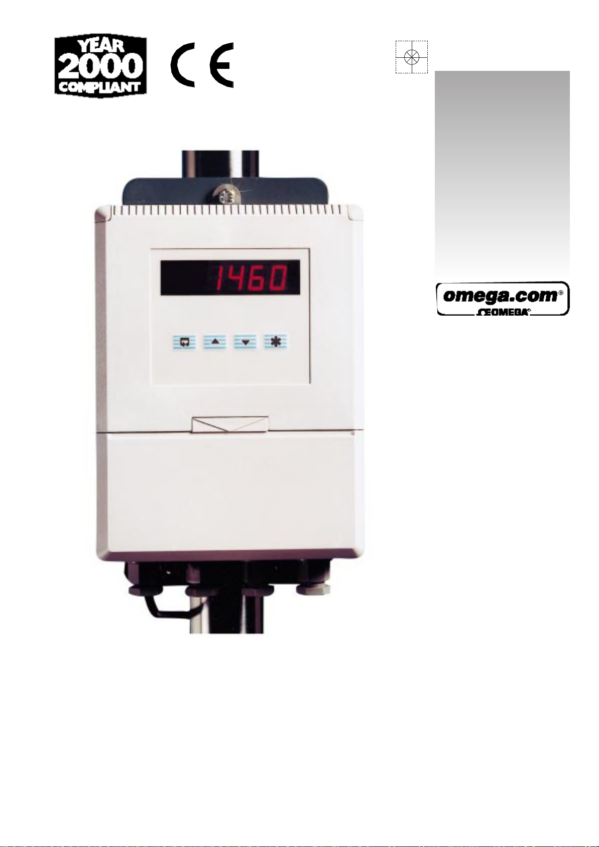
DP3410 & DP3411 SERIES
W all Mount
Universal T emperature & Pr ocess
Indicators
Page 2

WARRANTY/DISCLAIMER
OMEGA ENGINEERING, INC. warrants this unit to be free of defects in materials and workmanship
for a period of 37 months from date of purchase. OMEGA Warranty adds an additional one (1)
month grace period to the normal three (3) year product warranty to cover handling and
shipping time. This ensures that OMEGA’s customers receive maximum coverage on each product.
If the unit malfunctions, it must be returned to the factory for evaluation. OMEGA’s Customer Service
Department will issue an Authorized Return (AR) number immediately upon phone or written
request. Upon examination by OMEGA, if the unit is found to be defective, it will be repaired or
replaced at no charge. OMEGA’s WARRANTY does not apply to defects resulting from any action of
the purchaser, including but not limited to mishandling, improper interfacing, operation outside of
design limits, improper repair, or unauthorized modification. This WARRANTY is VOID if the unit
shows evidence of having been tampered with or shows evidence of having been damaged as a
result of excessive corrosion; or current, heat, moisture or vibration; improper specification;
misapplication; misuse or other operating conditions outside of OMEGA’s control. Components
which wear are not warranted, including but not limited to contact points, fuses, and triacs.
OMEGA is pleased to offer suggestions on the use of its various products. However,
OMEGA neither assumes responsibility for any omissions or errors nor assumes liability
for any damages that result from the use of its products in accordance with information
provided by OMEGA, either verbal or written. OMEGA warrants only that the parts
manufactured by it will be as specified and free of defects. OMEGA MAKES NO OTHER
WARRANTIES OR REPRESENTATIONS OF ANY KIND WHATSOEVER, EXPRESS OR
IMPLIED, EXCEPT THAT OF TITLE, AND ALL IMPLIED WARRANTIES INCLUDING ANY
WARRANTY OF MERCHANTABILITY AND FITNESS FOR A PARTICULAR PURPOSE ARE
HEREBY DISCLAIMED. LIMITATION OF LIABILITY: The remedies of purchaser set forth
herein are exclusive, and the total liability of OMEGA with respect to this order, whether
based on contract, warranty, negligence, indemnification, strict liability or otherwise,
shall not exceed the purchase price of the component upon which liability is based. In
no event shall OMEGA be liable for consequential, incidental or special damages.
CONDITIONS: Equipment sold by OMEGA is not intended to be used, nor shall it be used: (1) as a
“Basic Component” under 10 CFR 21 (NRC), used in or with any nuclear installation or activity; or
(2) in medical applications or used on humans. Should any Product(s) be used in or with any
nuclear installation or activity, medical application, used on humans, or misused in any way,
OMEGA assumes no responsibility as set forth in our basic WARRANTY / DISCLAIMER language,
and, additionally, purchaser will indemnify OMEGA and hold OMEGA harmless from any liability
or damage whatsoever arising out of the use of the Product(s) in such a manner.
RETURN REQUESTS / INQUIRIES
Direct all warranty and repair requests/inquiries to the OMEGA Customer Service Department.
BEFORE RETURNING ANY PRODUCT(S) TO OMEGA, PURCHASER MUST OBTAIN AN
AUTHORIZED RETURN (AR) NUMBER FROM OMEGA’S CUSTOMER SERVICE DEPARTMENT (IN
ORDER TO AVOID PROCESSING DELAYS). The assigned AR number should then be marked on the
outside of the return package and on any correspondence.
The purchaser is responsible for shipping charges, freight, insurance and proper packaging to
prevent breakage in transit.
FOR WARRANTY
RETURNS, please have the
following information available BEFORE
contacting OMEGA:
1. Purchase Order number under which the
product was PURCHASED,
2. Model and serial number of the product
under warranty, and
3. Repair instructions and/or specific problems
relative to product.
OMEGA’s policy is to make running changes, not model changes, whenever an improvement is possible.
This affords our customers the latest in technology and engineering.
OMEGA is a registered trademark of OMEGA ENGINEERING, INC.
© Copyright 1998 OMEGA ENGINEERING, INC. All rights reserved. This document may not be copied,
photocopied, reproduced, translated, or reduced to any electronic medium or machine-readable form, in
whole or in part, without the prior written consent of OMEGA ENGINEERING, INC.
FOR NON-WARRANTY REPAIRS,
OMEGA for current repair charges. Have the
following information available BEFORE
contacting OMEGA:
1. Purchase Order number to cover the COST of
the repair,
2. Model and serial number of the products, and
3. Repair instructions and/or specific problems
relative to the product.
consult
Page 3
GETTING STARTED
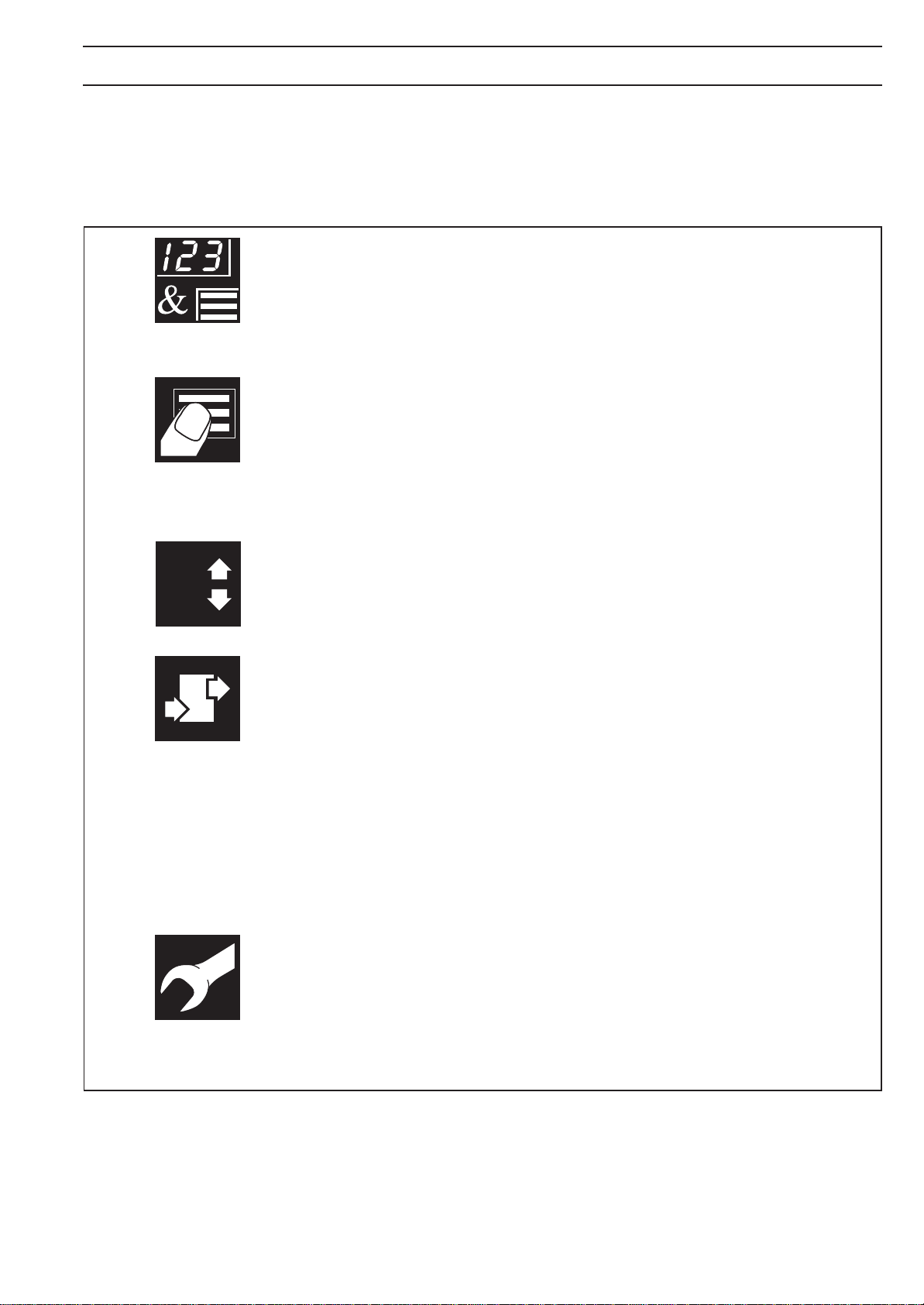
This manual is divided into 5 sections which contain all the information needed to
install, configure, set up and operate the instrument. Each section is identified
clearly by a symbol as shown below.
Displays and Controls
• Displays and function keys
• LED Indication
• Error Messages
Operator Mode (Level 1)
• Operator menus for:
– Standard Indicator
– Totalizer/Batch Controller
– Maximum/Minimum/Average Indicator
8
Set Up Mode (Level 2)
• Alarm trip points
• Totalizer functions
Configuration Mode (Levels 3 and 4)
• Accessing the configuration levels
• Level 3
– Hardware assignment and input type
– Alarm types and hysteresis
– Operator functions and totalizer setup
– Digital input and serial communications
• Level 4
–
Ranges and passwords
Installation
• Siting
• Mounting
• Electrical connections
Symbol Identification and Section Contents
1
Page 4

CONTENTS
1 DISPLAYS AND FUNCTION KEYS ................................................................ 3
1.1 Introduction .............................................................................................. 3
1.2 Use of Function Keys .............................................................................. 4
1.3 LED Alarms and Indicators ..................................................................... 5
1.4 Error Messages ....................................................................................... 6
2 OPERATOR MODE ......................................................................................... 7
2.1 Introduction .............................................................................................. 7
2.2 Operating Page – Standard .................................................................... 8
2.3 Operating Page – Totalizer ..................................................................... 9
2.4 Operating Page – Math Functions ........................................................ 11
3 SET UP MODE ............................................................................................... 13
3.1 Introduction ............................................................................................ 13
3.2 Set Up Level .......................................................................................... 14
4 CONFIGURATION MODE ............................................................................. 18
4.1 Introduction ............................................................................................ 18
4.2 Accessing the Configuration Mode ....................................................... 18
4.3 Basic Configuration (Level 3)................................................................ 20
4.3.1 Hardware Assignment and Input Type ...................................... 20
4.3.2 Alarms ........................................................................................ 22
4.3.3 Operator Functions and Totalizer Set Up ................................. 26
4.3.4 Digital Input and Serial Communications .................................. 28
4.4 Ranges and Passwords (Level 4) ......................................................... 30
5 INSTALLATION ............................................................................................. 33
5.1 Siting .................................................................................................... 33
5.2 Mounting ................................................................................................ 35
5.3 Cable Glands and Conduit Fixings ....................................................... 37
5.3.1 Cable Glands (IEC – 20mm) ..................................................... 37
5.3.2 Conduit Adapters (N. American – 0.5 in.) ................................. 37
5.3.3 Cable Glands (N. American – 0.5 in.) ....................................... 38
5.4 Electrical Connections........................................................................... 39
5.4.1 Relay Contact Ratings ............................................................... 39
5.4.2 Arc Suppression......................................................................... 39
5.4.3 Logic Output ...............................................................................39
5.4.4 Control or Retransmission Analog Output ................................ 39
2
Page 5
1 DISPLAYS AND FUNCTION KEYS
Information.
The fold-out page inside on the back cover of this
manual shows all the frames in the programming
levels. Space is provided on the page for writing the
programmed setting or selection for each frame.
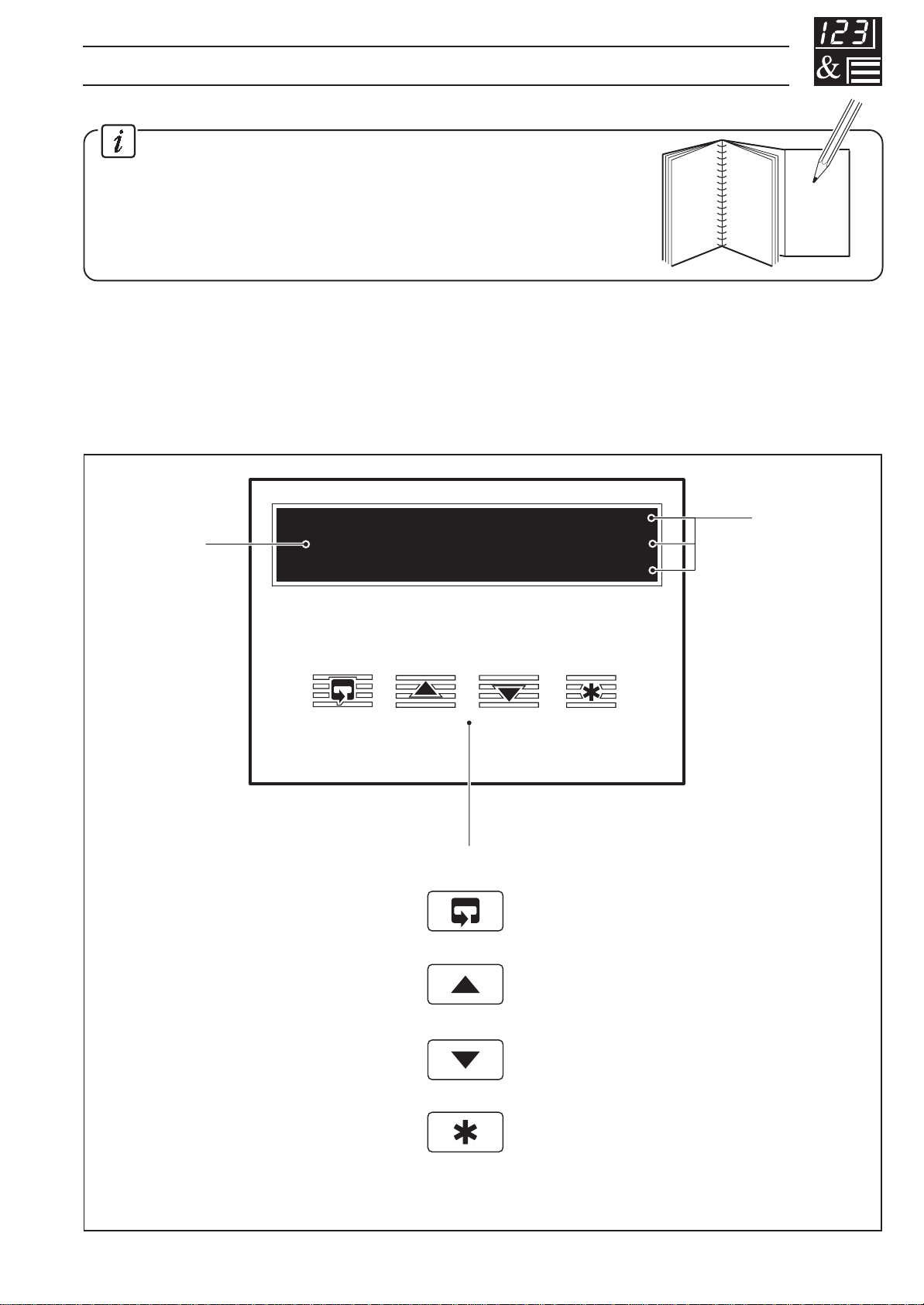
1.1 Introduction – Fig. 1.1
The instrument front panel display, function keys and LED indicators are shown in
Fig. 1.1.
Display
888888
Function Keys
Parameter Advance
A1
A2
A3
Alarm LEDs
(invisible
when off)
Raise
Lower
Multi-function Key
Fig. 1.1 Front Panel Display, Function Keys and Indicators
3
Page 6
…1 DISPLAYS AND FUNCTION KEYS
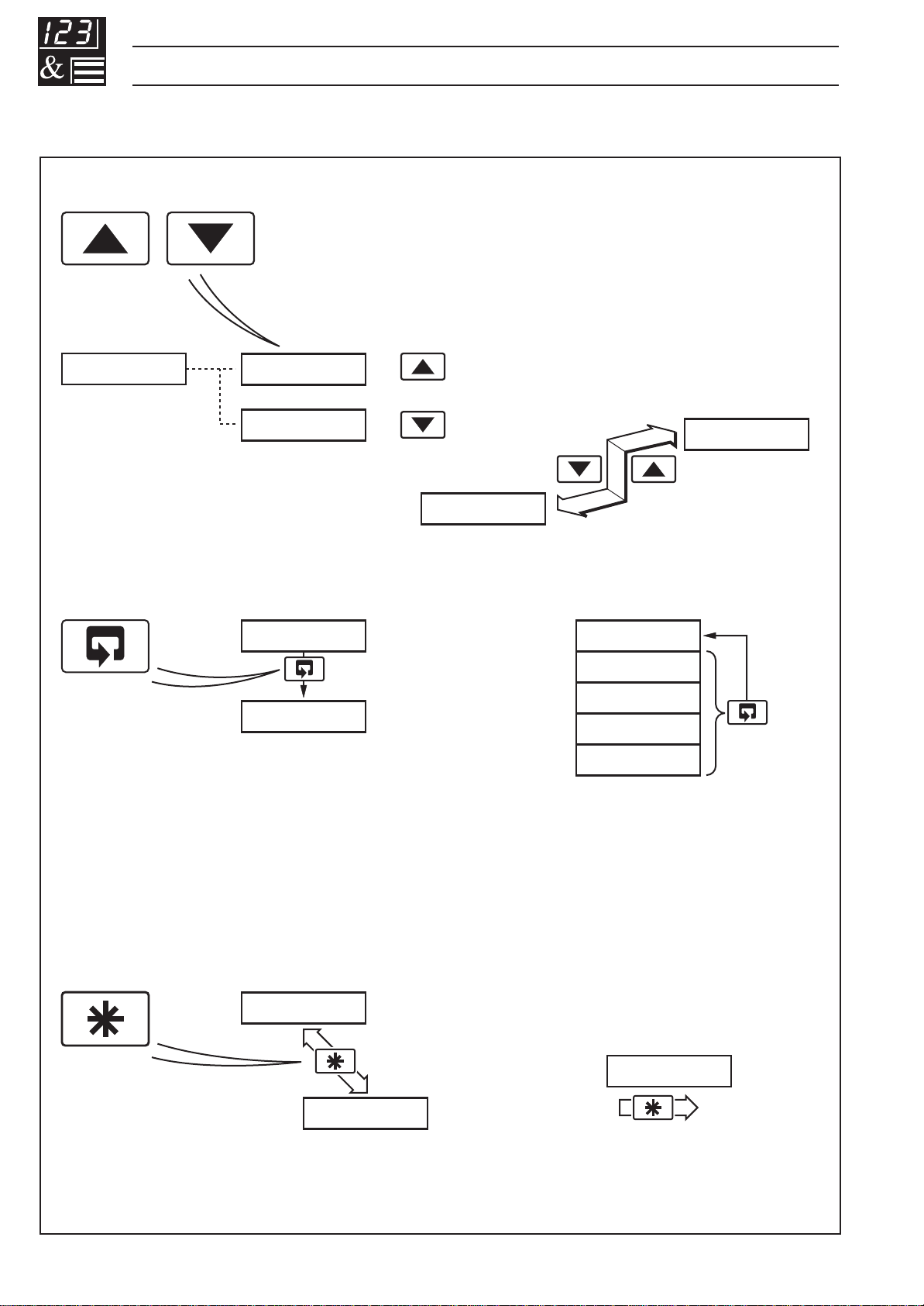
1.2 Use of Function Keys – Fig. 1.2
A – Raise and Lower Keys
100.0 100.1
99.9
Use to change/set a parameter value…
B – Parameter Advance Key
+
–
LEVEL1
100.1
Use to advance to the next
frame within a level…
or…
LEVEL1
Frame 1
(top of level)
Frame 2
…move between levels
LEVELx
100.1
or…
200.2
300.3
400.4
…select the top (LEVEL) frame
from within a level
LEVEL2
Press and
hold
Note. This key also stores any changes made in the previous frame
C – Multi-function Key
CodE
0
Use to view a parameter setting or selection…
Fig. 1.2 Use of Function Keys
4
or…
…select individual characters in a frame
123456
Page 7

1 DISPLAYS AND FUNCTION KEYS…
1.3 LED Alarms and Indicators
Alarm LEDs
LED Status
All Flashing
• Indicator is in the Configuration Mode – see Section 4.2.
A1
A2
A3
Alarm 1
Alarm 2
Alarm 3
A1, A2 and A3
• Flash when Alarm is active (off when inactive).
• Lit constantly when Alarm 1 is an active latched alarm which has
been acknowledged
Fig. 1.3 LED Alarms and Indicators
5
Page 8
…1 DISPLAYS AND FUNCTION KEYS
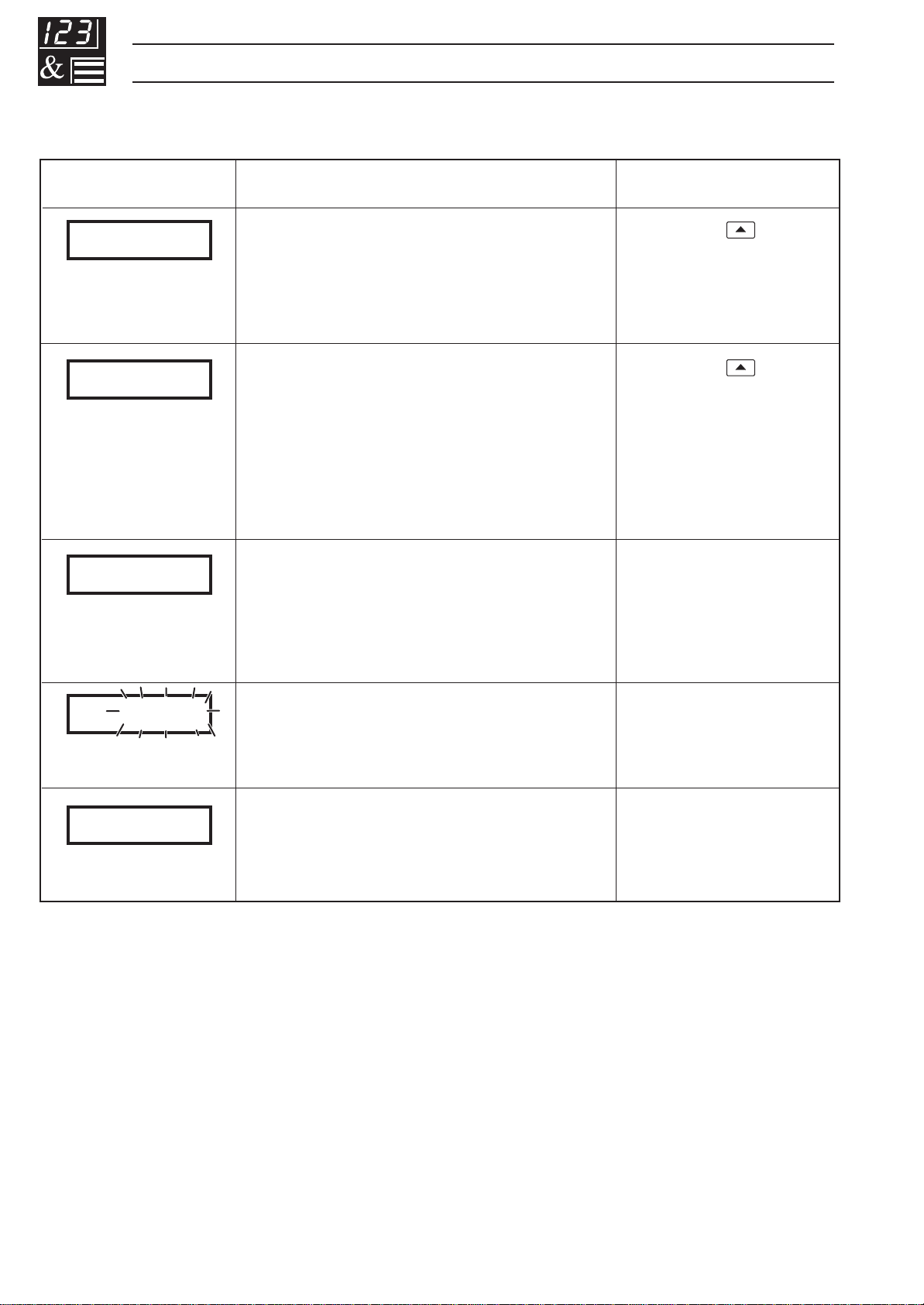
1.4 Error Messages
Display Error/Action
Calibration error
CALErr
Turn power off and on again (if the
error persists contact the Service
Organization).
Configuration error
CFGErr
The configuration and/or set up
data for the instrument is
corrupted. Turn power off and on
again (if error persists, check
configuration/set up settings).
A to D Converter fault
Ad Err
The analog to digital converter is
not communicating correctly.
To Clear Display
Press the
Press the key
Turn mains power
off and on again. If
the error persists,
contact the Supplier.
key
9999
DPtErr
Process variable over/under
range
Option board error
Communications to the option
board have failed.
Restore valid
input
Contact the Supplier
6
Page 9

2 OPERATOR MODE
2.1 Introduction
Operator Mode (Level 1) is the normal day-to-day mode of the instrument.
Frames displayed in Level 1 are determined by the indicator functions which are
selected during configuration of the instrument – see Section 4.
Note. Only the operating frames relevant to the configured functions are
displayed in Operator Mode.
The three indicator functions are:
• Standard Indicator – page 8
• Indicator with Totalization – page 9
• Indicator with Max./Min./Average – page 11
7
Page 10
…2 OPERATOR MODE
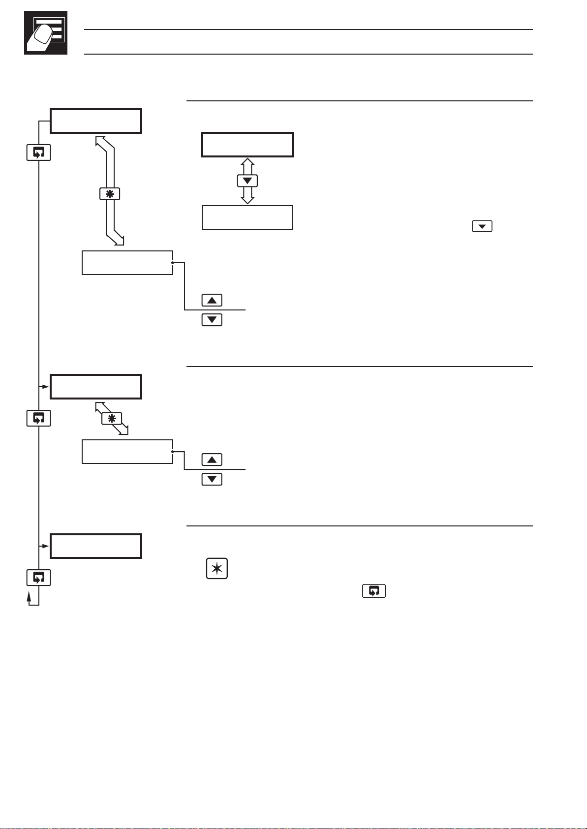
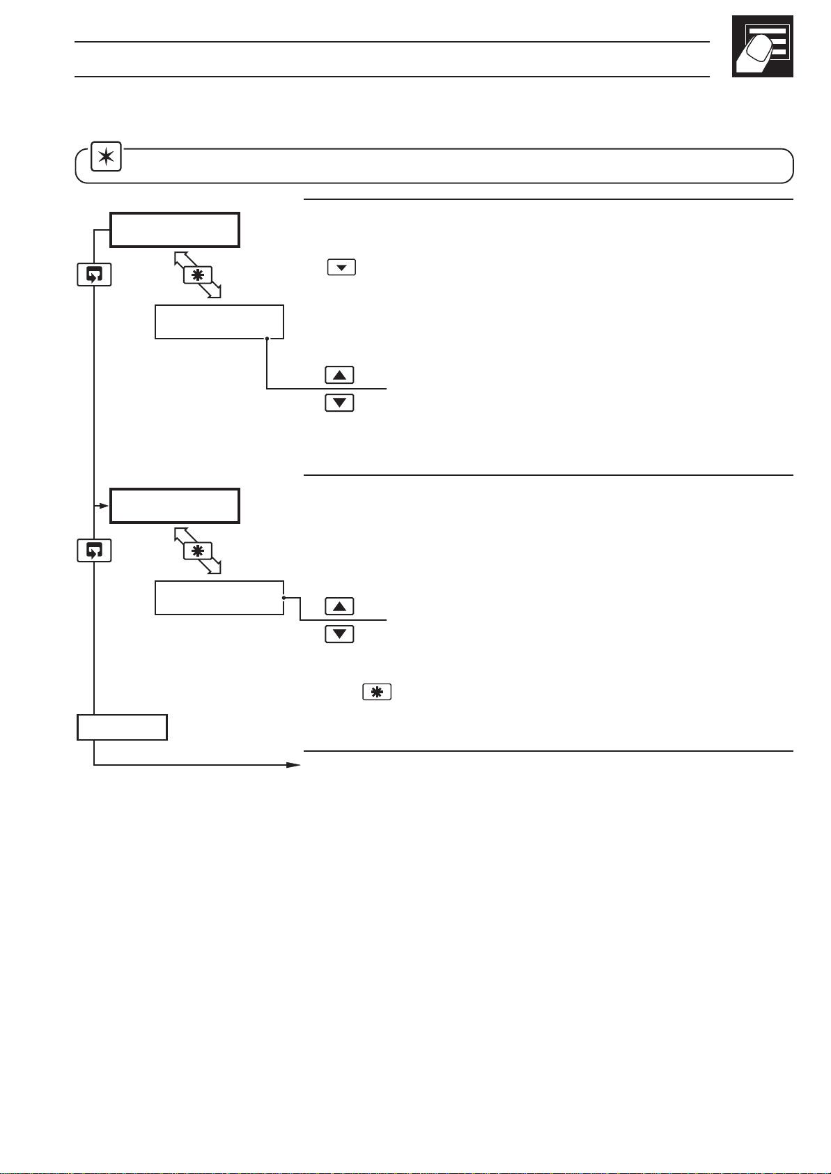
2.2 Operating Page – Standard (Level 1)
2145.3
UN-ACK
CodE
Process Variable
Normally displayed in engineering
2145.3
units.
To view the process variable in
27.6
•1
Global Alarm Acknowledge (latch alarms only)
UN-ACK. – alarm unacknowledged
ACK. – acknowledged
Security Password
Enter the correct password to access the set up level
electrical units, press the
key.
(Level 2) or the configuration level (Levels 3 and 4).
The default code is 0.
------
[0 to 9999]
Level 1
LEVEL1
Note. To select this frame from anywhere in this
level, press and hold the
•1 Only displayed if there is an active latch alarm.
key.
8
Page 11
2 OPERATOR MODE…
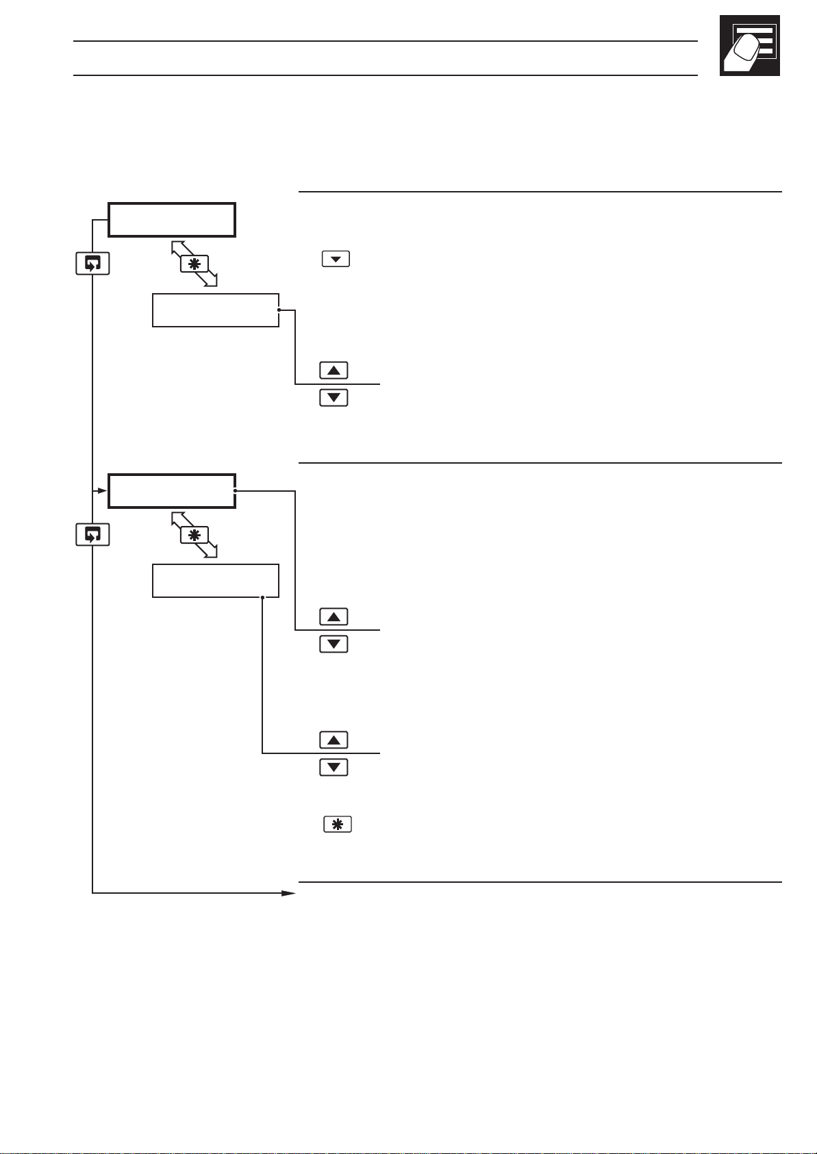
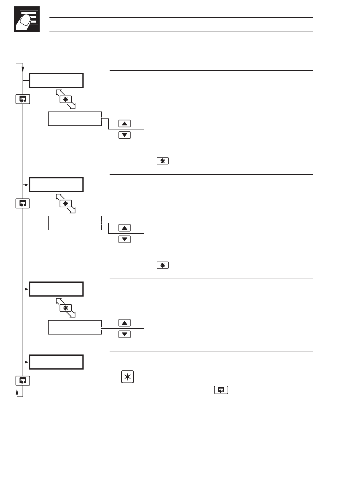
2.3 Operating Page – Totalizer (Level 1)
These frames are only displayed if the totalizer function is enabled in the
configuration level – see Section 4.3.3
2145.3
ACK-n
123456
rSt-n
•1
•1
Process Variable
To view the input value (in electrical units), press the
key.
Global Alarm Acknowledge (latch alarms only)
UN-ACK. – alarm unacknowledged
ACK. – acknowledged
Totalizer Value
When this frame is selected, the current counter
status is displayed (
Stop/Start
t–GO or t-StOP).
t–GO – start totalizer
t-StOP – stop totalizer
Reset
rSt-Y – reset totalizer
rSt-n – do not reset totalizer
To reset the totalizer, select
key.
Continued on next page.
•1 Totalizer stop/go and reset from these frames can be disabled – see
Section 4.3.3.
A digital input can also be used to start/stop or reset the totalizer – see
rSt-Y, then press the
Section 4.3.4
9
Page 12
…2 OPERATOR MODE
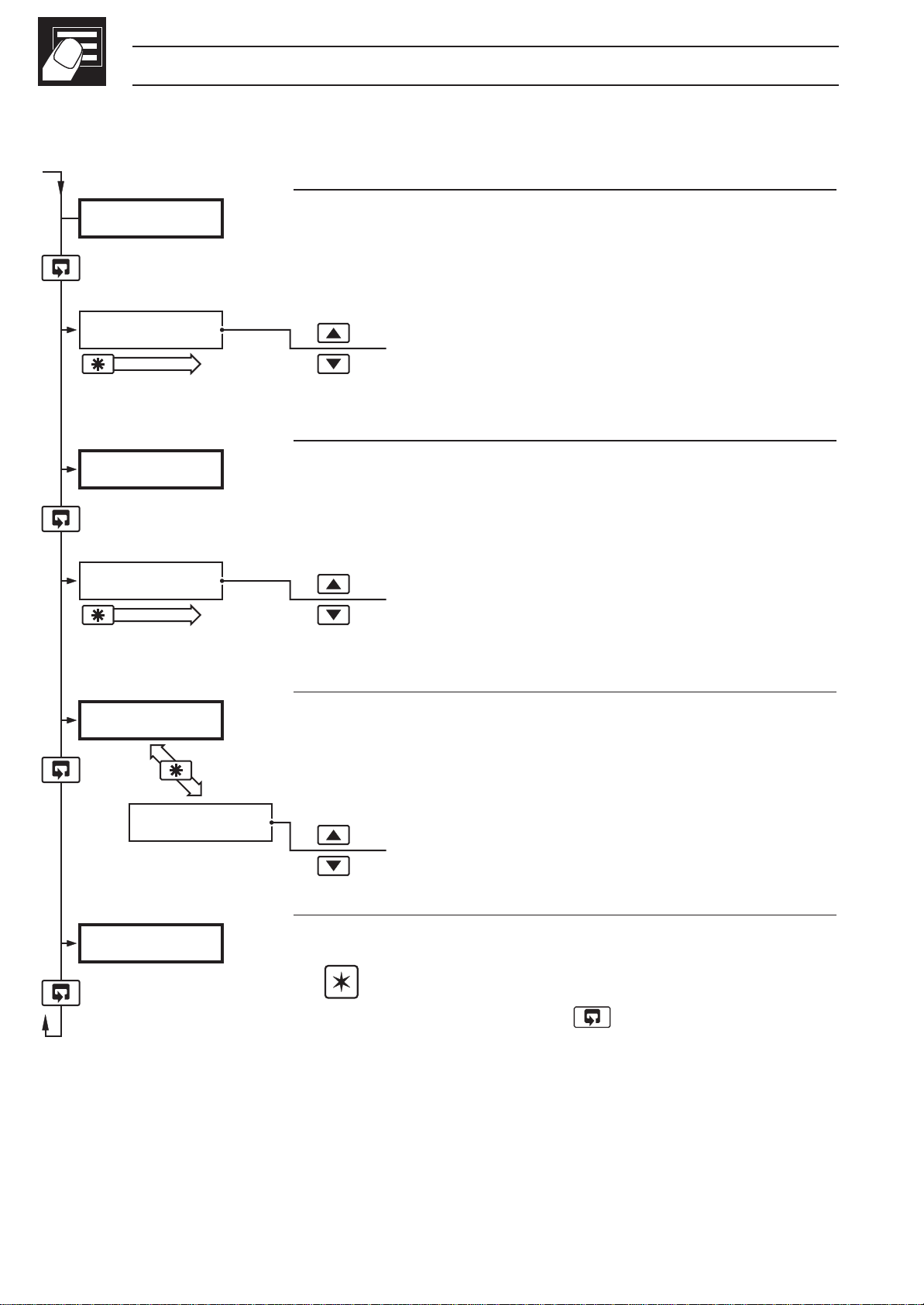
…2.3 Operating Page – Totalizer (Level 1)
PrESEt
000000
Select Digit
PrEdEt
999999
Select Digit
•2
Preset Total
This is the value the batch total is set to when it is reset
•1
[000000 to 999999 flow units]
Predetermined Total
When the predetermined total is reached, the batch
total is reset (with wrap on) or stops (wrap off),
depending on the wrap setting – see Section 4.3.3.
•1
[000000 to 999999 flow units]
CodE
Security Password
Enter the correct password to access the set up level
or the configuration level.
------
[0 to 9999]
LEVEL
•1 The predetermined value should be greater than the preset value when the
totalizer is counting up and lower than the preset value when the totalizer is
Level 1
Note. To select this frame from anywhere in this
page, press and hold the
key.
counting down.
•2 Only displayed if enabled in the configuration level – see Section 4.3.3.
10
Page 13
2 OPERATOR MODE…
2.4 Operating Page – Max./Min./Average Functions (Level 1)
Note. It is possible to display totalizer and math functions together.
Process Variable
2145.3
To view the input value (in electrical units), press the
key.
UN-ACK
Global Alarm Acknowledge (latch alarms only)
UN-ACK. – alarm unacknowledged
ACK. – acknowledged
A 140.5
•1
rSt-n
Average Value
This is the mean average value of the process
variable input, since the average was last reset.
rSt-Y – reset
rSt-n – do not reset
To reset the average value, select
the
key.
H150.2
Continued on next page.
•1 This frame can be disabled – see Section 4.3.3.
The reset function in this frame can be disabled – see Section 4.3.3.
rSt-Y then press
The average value is reset automatically on power-up, and can also be reset
from a digital input – see Section 4.3.4.
11
Page 14
…2 OPERATOR MODE
…2.4 Operating Page – Math Functions (Level 1)
H150.2
rSt-n
L130.8
rSt-n
•1
•1
Maximum Value
This is the maximum value of the process variable
since the maximum was reset.
rSt-Y – reset
rSt-n – do not reset
To reset the maximum value, select
press the
Minimum Value
This is the minimum value of the process variable
since the minimum was reset.
rSt-Y – reset
rSt-n – do not reset
key.
rSt-Y then
To reset the minimum value, select
press the
CodE
------
LEVEL1
•1 This frame can be disabled – see Section 4.3.3.
Security Code
Enter the correct code to access the set up level or the
configuration level.
[0 to 9999]
Level 1
Note. To select this frame from anywhere in this
page, press and hold the
key.
rSt-Y then
key.
12
The reset function in this frame can be disabled – see Section 4.3.3.
The average value is reset automatically on power-up, and can also be reset
from a digital input – see Section 4.3.4.
Page 15

3 SET UP MODE
8
3.1 Introduction
To access the Set Up Level (Level 2) the correct set up or configuration level
password must be entered in the security password frame (
– see Sections 2.2 to 2.4.
LEVEL2
A1xx
Level 1 –
Operating Level
LEVEL1
Correct
Password
A2xx
A3xx
Security
Password
CodE x
123456
t-GO
SEC.tot
CodE) in Level 1
Level 2 – Set Up
Alarm 1 Trip Point
Alarm 2 Trip Point
Alarm 3 Trip Point
Batch Total
Totalizer Stop/Go
Secure Total/Reset
PrESEt
PrEdEt
A xxxx
H xxxx
L xxxx
0AdJ
Fig. 3.1 Accessing the Set Up Level (Level 2)
Preset Batch Total
Predetermined
Batch Total
Average Value
Maximum Value
Minimum Value
Offset Adjustment
13
Page 16

8
3.2 Set Up Level (Level 2)
…3 SET UP MODE
LEVEL2
A1hP
100.1
A1 HYS
•1
•2
Level 2
Note. To select this frame from anywhere in this
level, press and hold the
Alarm 1 Trip Point
Alarm type:
Process and Latched Alarms in Eng. units.
Rate Alarms ±0.5 to 500% of Eng. Span/hr.
Alarm 1 Hysteresis Value
A1.hP = High process
A1.LP = Low process
A1.HL = Latched high process
A1.LL = Latched low process
A1.Fr = Fast Rate
A1Sr = Slow Rate
key.
A2LP
A2 HYS
A3hP
12.5
200.2
27.9
•1
•2
[In engineering units]
Alarm 2 Trip Point
Alarm type
[In engineering units]
Alarm 2 Hysteresis Value
[In engineering units]
Continued on next page.
•1 Not displayed if the alarm is disabled ('NONE' selected) – see Section 4.3.2.
•2 Only displayed if custom alarm hysteresis is selected – see Section 4.3.2
Not displayed if 'Rate' Alarm type is selected.
14
Page 17

…3.2 Set Up Level (Level 2)
3 SET UP MODE…
8
A3hP
300.3
A3 HYS
34.6
123456
•1
•2
•3
•4
Alarm 3 Trip Point
Alarm type
[In engineering units]
Alarm 3 Hysteresis Value
[In engineering units]
Totalizer Value
rSt-Y – reset
rSt-n – do not reset
rSt-n
rSt-Y, then
t-GO
•3
To reset the maximum value, select
press the
Totalizer Stop/Go
t–GO – start totalizer
t-StOP – stop totalizer
key.
t-StOP
Setting to
the predetermined value. Setting to
the totalizer at its present value.
SEC.tOt
Continued on next page
•1 Not displayed if the alarm is disabled ('NONE' selected) – see Section 4.3.2
t-GO starts the totalizer counting towards
t-StOP holds
•2 Only displayed if custom alarm hysteresis is selected – see Section 4.3.2
Not displayed if 'Rate' Alarm type is selected.
•3 Only displayed if enabled in the Configuration Level – see Section 4.3.3
•4 A digital input can also be used to reset the batch total.
15
Page 18

8
…3.2 Set Up Level (Level 2)
…3 SET UP MODE
SECtOt
456789
rSt-n
PrESEt
•1
•2
Secure Total
The secure total is independent of the batch total value.
When 999999 or 000000 is reached, the total is reset
and then continues counting.
Total
Reset
rSt-Y – reset totalizer
rSt-n – do not reset totalizer
To reset, select
Preset Batch Total
This is the value the batch total is set to when it is reset.
rSt-Y then press the key.
[000000 to 999999]
000000
•2
Predetermined Batch Total
PrEdEt
When this value is reached the batch total either resets
(with wrap on) or stops (wrap off) – see Section 4.3.3.
999999
A140.5
Continued on next page.
•1 Only displayed if enabled in the Configuration Level – see Section 4.3.3.
[000000 to 999999]
•2 The preset value must be lower than the predetermined value when
counting up, and greater than the predetermined value when counting down.
16
Page 19

…3.2 Set Up Level (Level 2)
3 SET UP MODE…
8
A140.5
rSt-n
H150.2
rSt-n
•1
•2
Average Value
This is the mean average value of the process variable
input since the average was reset.
rSt-Y – reset
rSt-n – do not reset
To reset, select
Maximum Value
This is the maximum value of the process variable
since the maximum was reset.
rSt-Y – reset
rSt-n – do not reset
To reset, select
rSt-Y then press the key.
rSt-Y then press the key.
L130.8
rSt-n
OAdJ
1.0
•2
Minimum Value
This is the minimum value of the process variable since
the minimum was reset.
rSt-Y – reset
rSt-n – do not reset
To reset, select
Offset Adjustment
An offset can be applied to the process variable input to
enable spot calibration or the removal of system errors.
[±10% of engineering range]
rSt-Y then press the key.
•1 The average value i s reset automatically on power-up and can also be reset
from a digital input – see Section 4.3.4.
•2 The maximum and minimum values are reset automatically on power-up and
can also be reset from a digital input – see Section 4.3.4.
17
Page 20

4 CONFIGURATION MODE
4.1 Introduction
The Configuration Mode comprises two levels (3 and 4) as shown in Fig. 4.2.
Configuration Level 3 is divided into four frames. For most simple applications it is
only necessary to set up the parameters in the first frame.
Note.
When in the configuration level:
• All the LED indicators flash.
• All relays and logic outputs are turned off.
• The analog output reverts to 0% (4mA) output level.
4.2 Accessing the Configuration Mode – Fig. 4.1
The Configuration Mode is accessed by entering the correct password in Level 1
(see Sections 2.2 to 2.4). The configuration password is set up in Level 4.
LEVEL4
Level 1 –
Operating Level
LEVEL3
LEVEL2
LEVEL1
Correct
CodE x
Security
Password
Fig. 4.1 Accessing the Configuration Level (Levels 3 and 4)
Password
18
Page 21

4 CONFIGURATION MODE…
Level 3
Hardware
Configuration
Alarms and
Set Points
Custom Operator
Settings
LEVEL3
A 1KC0
b 1KC0
C 1KC0
d 1KC0
E 0000
F 0000
G 0000
H 0000
J 0000
K 0000
L 0000
N 0000
LEVEL4
ENG HI
ENG LO
rEt HI
rEt LO
CNt HI
CUtOFF
S-PASS
Level 4
Engineering
Range High
Engineering
Range Low
Retransmission
Range High
Retransmission
Range Low
Totalizer Count
High
Totalizer Count
Cut-Off
Set Up Level
Password
Digital Input and
Serial Comms.
P 0000
r 0000
S 0000
t 0000
Fig. 4.2 Configuration Levels
C-PASS
Addr.
Configuration
Level Password
MODBUS Address
19
Page 22

…4 CONFIGURATION MODE
4.3 Basic Configuration (Level 3) – Fig. 4.3
4.3.1 Hardware Assignment and Input Type
LEVEL3
A 1KC0
B 1KC0
C 1KC0
d 1KC0
Level 3
Note. To select this frame from anywhere in this
level, press and hold the
'ABCD' Settings
The first character (A, B, C or D) identifies the
parameter to be changed. The current setting is
indicated by a flashing letter. Parameter options are
shown in Fig. 4.3.
key for a few seconds.
A = Hardware configuration
b = Input type and range
C = Temperature units
d = No. of decimal points
E 1203
Continued on page 22.
Information.
Count High Calculation
Convert flow rate into units/sec =
Count High = resultant must be >0.001 and <99.999pps.
Counter factor is the engineering value of the least significant digit shown on
the totalizer display – see Section 4.3.3.
Totalizer Count Pulse
The totalizer count pulse is on for a preset time of 250ms and off for a minimum
of 250ms.
units/sec
counter factor
actual engineering flow rate
flow range time units (in seconds)
20
Page 23

4 CONFIGURATION MODE…
A 1KC0
A – Hardware Configuration
Supply Hz Relay 1 Relay 2 Relay 3* Logic O/P Analog O/P
50 60
1AAlarm 1 Alarm 2 Alarm 3 TCP** PV
2bAlarm 1 Alarm 2 Alarm 3 TWP** PV
3CTCP** Alarm 1 Alarm 2 TWP** PV
4DTWP** Alarm 1 Alarm 2 TCP** PV
5EAlarm 1 Alarm 2 Alarm 3 TCP** PV Average
U Custom Custom Custom Custom Custom
TCP = Totalizer Count Pulse TWP = Totalizer Wrap Pulse PV = Process Variable
* Not available if MODBUS option fitted.
** Pulse energizes assigned relay
Source Source Source Source Source
B – Input Type and Range Configuration
b 1KC0
Display
b T/C Type B
E T/C Type E
J T/C Type J
K T/C Type K
n T/C Type N
r T/C Type R
S T/C Type S
t T/C Type T
P PT100 RTD
C – Temperature Units
C 1KC0
Display Temperature Units
C Degrees C*
F Degrees F*
0 No temperature units
* Temperature inputs only
Display
1 0 to 20 mA
2 4 to 20 mA
3 0 to 5 V
4 1 to 5 V
6 0 to 50 mV
7 4 to 20 mA (square root linearizer)
U Custom Configuration
d 1KC0
Display
0 xxxx
1 xxx . x
2 xx . xx
3 x . xxx
4 x . xxxx
D – Process Variable
Display Decimal Places
Fig. 4.3 Hardware Configuration and Input/Output Ranges
21
Page 24

…4 CONFIGURATION MODE
4.3.2 Alarms – Figs. 4.4, 4.5 and 4.6
Note. All relays are de-energized in the alarm state.
'EFGH' Settings
E 0000
F 0000
G 0000
The first character (E, F, G or H) identifies the
parameter to be changed. The current setting is
indicated by a flashing letter. Parameter options are
shown in Fig. 4.4.
E = Alarm 1 type
J 0000
H 0000
F = Alarm 2 type
G = Alarm 3 type
H = Alarm hysteresis
Continued on page 26.
22
Page 25

4 CONFIGURATION MODE…
E 0000
E – Alarm 1 Type
Display
0 None
1 High Process
2 Low Process
3 High Latch
4 Low Latch
5 Fast Rate
6 Slow Rate
F – Alarm 2 Type
F 0000 G 0000
Display
0 None
1 High Process
2 Low Process
3 High Latch
4 Low Latch
5 Fast Rate
6 Slow Rate
Display
0 None
1 High Process
2 Low Process
3 High Latch
4 Low Latch
5 Fast Rate
6 Slow Rate
G – Alarm 3 Type
h 0000
Display
0 None
1 0.1%
2 0.2%
3 0.5%
4 1.0%
5 2.0%
6 5.0%
U Custom
H – Alarm Hysteresis
Value in % of
engineering range
Value in engineering units
Fig. 4.4 Alarm Set Up
Note. When custom
alarm hysteresis is selected,
the alarm hysteresis values are
set individually in the
Level – see Section 3.2.
Set Up
23
Page 26

…4 CONFIGURATION MODE
…4.3.2 Alarms – Figs. 4.4, 4.5 and 4.6
Hysteresis
Hysteresis
Process
Variable
Alarm on
(Relay
de-energized)
Alarm off
(Relay
energized)
High Process
Low Process
Trip point
Alarm on
(Relay
de-energized)
Alarm off
(Relay energized)
Information.
For latch alarms, the relay remains de-energized until acknowledged in
Level 1 (or by a digital input).
Fig. 4.5 Process Alarm Action
24
Page 27

% Engineering Range
100
50
4 CONFIGURATION MODE…
10
Hours
12 3 4
t (191 secs)
Alarm On
(Relay de-energized)
Alarm Off
(Relay energized)
Information. The example above shows a fast rate alarm with a trip
value of 10% of the engineering span per hour on an engineering range of
0.0 to 100.0. The time taken to detect whether an alarm condition is
present or has cleared is calculated as follows:
t (191 secs)
5
t = 10.81 +
trip value (10% eng. span per hour)
t = 191 seconds
Fig. 4.6 Rate Alarm Action
1800
25
Page 28

…4 CONFIGURATION MODE
4.3.3 Operator Functions and Totalizer Set Up – Fig. 4.7
'JKLN' Settings
J 0000
K 0000
L 0000
The first character (J, K, L or N) identifies the
parameter to be changed. The current setting is
indicated by a flashing letter. Parameter options are
shown in Fig. 4.7.
J = Totalizer set-up
P 0000
n 0000
K = No. of decimal places for totalizer
L = Operator level frame enable
n = Operator level functions enable/disable
Continued on page 28.
26
Page 29

4 CONFIGURATION MODE…
J 0000
Display
0 Off
1 Count Up, Wrap Off
2 Count Up, Wrap On
3 Count Down, Wrap Off
4 Count Down, Wrap On
J – Totalizer Set Up
L – Operator Level Frame Enable
K 0000
Display
0 xxxxxx
1 xxxxx.x
2 xxxx.xx
3 xxx.xxx
4 xx.xxxx
5 x.xxxxx
K – Totalizer Display
Decimal Places
L 0000
Display Max/Min Values Average Value Preset/Predetermined
Displayed Displayed Values Displayed
0 No No No
1 Yes No No
2 Yes Yes No
3 No Yes Yes
4 No No Yes
5 Yes No Yes
6 Yes Yes Yes
This frame determines which frames appear in the operating page (Level 1)
N – Operator Level Math Function & T otalizer Control Enable
n 0000
Display Totalizer Stop/Go Totalizer Reset Max./Min./Average
0 No No No
1 Yes No No
2 No Yes No
3 Yes No Yes
4 No Yes Yes
5 Yes Yes Yes
This frame determines which functions the operator can control
Fig. 4.7 Totalizer Set Up and Operator Functions
27
Page 30

…4 CONFIGURATION MODE
4.3.4 Digital Input and Serial Communications – Figs. 4.8 and 4.9
'PRST' Settings
P 0000
r 0000
The first character (P, R, S or T) identifies the
parameter to be changed and the current setting is
indicated by a flashing letter. Parameter options are
shown in Fig. 4.9.
S 0000
P = Digital input function
LEVEL4
t 0000
1 Totalizer Reset
r = Analog input filter
S = Serial communications configuration
t = Serial communications parity
Continued on page 30.
Reset
Stop
Lock
Unlock
4 Front Panel Lock out
Acknowledge
28
Go
2 Totalizer Stop/Go
Max
Min
3 Average Max/Min Reset
Information.
Digital input options 1, 2, 3 and 5 are edge-triggered to enable the front
panel keys to change the function when the digital input is operational.
Fig. 4.8 Digital Function Configuration
5 Alarm Acknowledge
Page 31

4 CONFIGURATION MODE…
P 0000 r 0000
P – Digital Input Function
Display
0 None
1 Totalizer Reset
2 Totalizer Stop/Go
3 Average, Max/Min Reset
4 Front Panel Lockout
5 Alarm Acknowledge
S 0000 t 0000
Display Baud Rate, 2/4 Wire
0 Off
1 2400, 2-Wire
2 2400, 4-Wire
3 9600, 2-Wire
4 9600, 4-Wire
S – Serial Communication
Configuration
Display
0 0 seconds
1 1 second
2 2 seconds
5 5 seconds
A 10 seconds
b 20 seconds
C 40 seconds
D 60 seconds
Display
0 None
1 Odd
2 Even
R – Analog Input Filter
T – Serial Communication
Parity
Note. Settings for options P, S and T are only available if the
appropriate option board is fitted.
Fig. 4.9 Digital Function and Serial Communications Configuration
29
Page 32

…4 CONFIGURATION MODE
4.4 Ranges and Passwords (Level 4)
LEVEL4
ENG HI
100.0
ENG LO
Level 4
Note. To select this frame from anywhere in this
level, press and hold the
Engineering (Display) Range
High Value
•1
[–9999 to 99999]
Low Value
key.
•1
0.0
rEt HI
Continued on next page…
•1 The engineering range high and low values are automatically set to the
maximum allowed value when thermocouple or RTD is selected in the
Configuration Level – see Section 4.3.1. This value can be modified if
required.
[–9999 to 99999]
30
Page 33

4 CONFIGURATION MODE…
…4.4 Ranges and Passwords (Level 4)
Retransmission Range
The retransmission range defines the engineering
range to be retransmitted.
rEt HI
rEt LO
CNt HI
100.0
100.0
High (20mA output)
•1
[–9999 to 99999 (in engineering units)]
Low (4mA output)
•1
[–9999 to 99999 (in engineering units)]
Continued on next page…
•1 The retransmission range high and low values are automatically set to the
maximum allowed value when thermocouple or RTD is selected in the
configuration level – see Section 4.3.1. This value can be modified if
required.
31
Page 34

…4 CONFIGURATION MODE
…4.4 Ranges and Passwords (Level 4)
CNt HI
1.00
cut.oFF
100.0
S-PASS
•1
•1
Totalizer Count High
This frame determines the count corresponding to the
full-scale input.
[0.000 and 99.999 pulses/second]
Cut-off
This frame sets the lowest flow value at which the
totalizer is to stop counting.
[In engineering units]
Set Up Password
This password enables access to the set-up level
0
C-PASS
0
Addr.
1
•2
(Level 2).
[0 to 9999]
Configuration Password
This password enables access to the configuration
levels. (Levels 3 and 4).
[0 to 9999]
MODBUS Address
This frame sets the MODBUS address.
[1 to 99]
•1 Only displayed if enabled in the configuration level – see Section 4.3.3.
•2 Only available if the appropriate option board is fitted.
32
Page 35

5 INSTALLATION
EC Directive 89/336/EEC
In order to meet the requirements of the EC Directive 89/336/EEC for EMC
regulations, this product must not be used in a non-industrial environment.
5.1 Siting – Figs 5.1 and 5.2
Close to Sensor
At Eye Level
Minimum
Sensor
Avoid Vibration
Fig 5.1 Siting – General Requirements
33
Page 36

…5 INSTALLATION
…5.1 Siting – Figs 5.1 and 5.2
Temperature Limits
–10°C
Min.
Humidity Limits
Environmental Limits
60°C
Max.
IP66/
NEMA-4X
Use Screened Cable
0 to 90% RH
+
Note. If it is not possible to avoid strong electrical and magnetic
fields, screened cables within earthed/grounded metal conduit must be
used.
34
Fig 5.2 Environmental Requirements
Page 37

5 INSTALLATION…
5.2 Mounting – Figs. 5.3 and 5.4
The instrument is designed for wall-mounting or pipe-mounting (see Fig. 5.4). The
pipe-mounting kit is suitable for both vertical and horizontal pipes. Overall
dimensions are shown in Fig. 5.3.
Dimensions in mm (in.)
161.5 (6.3)
250
(9.84)
Fixing Holes
(x3) 6.5 (0.25) Dia
68 (2.68)
214
(8.43)
69 (2.72)
Fixing Centers
42 (1.65)
200
(7.9)
Allowance for
Cable Bends
3
61(2
232
(9.13)
/
8
Fixing Centers
) O.D. Pipe
Fig. 5.3 Overall Dimensions
Vertical Pipe shown
for example only
35
Page 38

…5 INSTALLATION
…5.2 Mounting – Figs. 5.3 and 5.4
2
Drill suitable holes
1
Wall-mounting
Mark fixing centers (see Fig. 5.3)
3
Fix instrument to wall using suitable fixings
Position plates over ‘U’ bolts
Pipe-mounting
Position ‘U’ bolts on pipe
2
1
3
Secure plates
36
4
Secure transmitter to mounting plate
Fig. 5.4 Mounting Details
Page 39

5 INSTALLATION…
Ferrule
Outer Nut
Seal
Alternative
Face Seal
Face
Seal
Hub
5.3 Cable Glands
and Conduit Fixings
5.3.1 Cable Glands
(IEC – 20mm) – Fig. 5.5
'O'-Ring
5.3.2 Conduit Adaptors
(N. American – 0.5 in.) – Fig. 5.6
Warning.
• Rigid conduit must NOT be
fitted to the Indicator.
• Indicator adapters must
incorporate a face seal.
• Torque settings for the hubs
and outer nuts on the specified
adaptors is 20ft.lbs minimum,
25ft.lbs. maximum.
Fig. 5.5 Cable Gland
(Supplied as Standard)
Note. Fittings may
vary for different makes.
Fig. 5.6 Conduit Adaptors
(Not Supplied)
37
Page 40

…5 INSTALLATION
5.3.3 Cable Glands (N. American – 0.5 in.) – Fig. 5.7
Warning.
• Indicator glands must be fitted with a face seal.
• Torque settings (hubs only) – 20ft. lbs minimum, 25ft. lbs. maximum.
• Outer nuts – hand tight plus a half turn only.
Information.
When fitting cable glands to the Indicator, start with an outer gland and also
temporarily fit a gland at the opposite end, to aid location of the transmitter
gland plate. Fit and tighten glands consecutively from initial gland.
Alternative
Face Seal
Face
Seal
Fittings vary
slightly for
different
makes
Outer Nut
Hub
38
Fig. 5.7 Cable Glands (Not Supplied)
Page 41

5 INSTALLATION…
5.4 Electrical Connections –
Figs. 5.8 and 5.9
Warning. Before making
any connections, ensure that the
instrument power supply, any
powered control circuits and high
common mode voltages are
switched off.
Note. The analog output and
the logic output share a common
positive and can be used at the
same time.
5.4.1 Relay Contact Ratings
Relay contacts are rated at:
5.4.4 Retransmission
Analog Output
Max. load 15V (750Ω at 20mA)
Isolation 500V from input (not
isolated from logic output)
Terminal Block
11 7
10 9 8
NC
Load Load
C
Suppression
component
NO
(B9303)
115/230V a.c. at 5A (noninductive)
250V d.c. 25W max.
5.4.2 Arc Suppression – Fig. 5.8
Arc suppression components are fitted
to relays 2 and 3 only. If relay 1 is
required to switch inductive loads, the arc
suppression component supplied must
be fitted across the contacts used.
5.4.3 Logic Output
18V d.c. at 20mA
Min. load 900Ω
Switched
Supply
Fig. 5.8 Fitting Arc Suppression
Components
Isolation 500V from input (not
isolated from retransmission
output)
39
Page 42

…5 INSTALLATION
1 2 14 15
N
L
85 to 265V AC
Mains Supply
+ –
24V DC Supply
See below
– +
3 4 5 6 7 8 9 10 11 12 13
RTD
TxPSU
T/C
–
3
Relay 1**
N/C
CN/O
16 17 18 19 20 21 22 23 24
N/O
Relay 2
mA
–
*
100Ω
N/C
C
2-wire Tx
Logic output
Analog output
*
100Ω
TX– TX+ RX– RX+C
+
–
+
2-lead RTD
RS485
–
3-lead RTD
lead
–
rd
3
+
input
Digital
4
14
15
+
+
–
2-wire
Transmitter
+
* Fit 100Ω resistor supplied
** Fit arc suppression components
Fig. 5.9 Electrical Connections
40
Page 43

CUSTOMER CONFIGURATION LOG
✍
LEVEL4
LEVEL3
A 1KC0
A B C D
E 0000
E F
J 0000
J K
P 0000
G H
L N
ENG HI
ENG LO
rEt HI
rEt LO
CNt HI
CUtOFF
S-PASS
P R
S T
C-PASS
Addr.
Page 44

CUSTOMER SET UP LOG
LEVEL1
CodE
8
✍
LEVEL2
A1xx
A2xx
A3xx
xxxxxx
t-GO
SEC.tot
PrESEt
PrEdEt
A xxxx
H xxxx
L xxxx
0AdJ
Instrument Serial Number:
Page 45

omega.com
OMEGAnet®On-Line Service Internet e-mail
http://www.omega.com info@omega.com
Servicing North America:
USA: One Omega Drive, Box 4047
ISO 9001 Certified Stamford, CT 06907-0047
Tel: (203) 359-1660 FAX: (203) 359-7700
e-mail: info@omega.com
Canada: 976 Bergar
Laval (Quebec) H7L 5A1
Tel: (514) 856-6928 FAX: (514) 856-6886
e-mail: info@omega.ca
For immediate technical or application assistance:
®
®
USA and Canada: Sales Service: 1-800-826-6342 / 1-800-TC-OMEGA
Customer Service: 1-800-622-2378 / 1-800-622-BEST
Engineering Service: 1-800-872-9436 / 1-800-USA-WHEN
TELEX: 996404 EASYLINK: 62968934 CABLE: OMEGA
SM
Mexico and
Latin America:
Tel: (95) 800-826-6342 FAX: (95) 203-359-7807
En Espan˜ol: (95) 203-359-7803 e-mail: espanol@omega.com
Servicing Europe:
Benelux: Postbus 8034, 1180 LA Amstelveen, The Netherlands
Tel: (31) 20 6418405 FAX: (31) 20 6434643
Toll Free in Benelux: 0800 0993344
e-mail: nl@omega.com
Czech Republic: ul. Rude armady 1868, 733 01 Karvina-Hranice
Tel: 420 (69) 6311899 FAX: 420 (69) 6311114
Toll Free: 0800-1-66342 e-mail: czech@omega.com
France: 9, rue Denis Papin, 78190 Trappes
Tel: (33) 130-621-400 FAX: (33) 130-699-120
Toll Free in France: 0800-4-06342
e-mail: france@omega.com
Germany/Austria: Daimlerstrasse 26, D-75392 Deckenpfronn, Germany
Tel: 49 (07056) 3017 FAX: 49 (07056) 8540
Toll Free in Germany: 0130 11 21 66
e-mail: info@omega.de
SM
SM
United Kingdom: One Omega Drive, River Bend Technology Centre
ISO 9002 Certified Northbank, Irlam, Manchester
M44 5EX, United Kingdom
Tel: 44 (161) 777-6611 FAX: 44 (161) 777-6622
Toll Free in the United Kingdom: 0800-488-488
e-mail: info@omega.co.uk
It is the policy of OMEGA to comply with all worldwide safety and EMC/EMI regulations that apply.
OMEGA is constantly pursuing certification of its products to the European New Approach Directives.
OMEGA will add the CE mark to every appropriate device upon certification.
The information contained in this document is believed to be correct, but OMEGA Engineering, Inc. accepts no liability
for any errors it contains, and reserves the right to alter specifications without notice.
WARNING: These products are not designed for use in, and should not be used for, patient-connected applications.
Page 46

Where Do I Find Everything I Need for
Process Measurement and Control?
OMEGA…Of Course!
TEMPERATURE
MU
Thermocouple, RTD & Thermistor Probes,
Connectors, Panels & Assemblies
MU
Wire: Thermocouple, RTD & Thermistor
MU
Calibrators & Ice Point References
MU
Recorders, Controllers & Process Monitors
MU
Infrared Pyrometers
PRESSURE, STRAIN AND FORCE
MU
Transducers & Strain Gauges
MU
Load Cells & Pressure Gauges
MU
Displacement Transducers
MU
Instrumentation & Accessories
FLOW/LEVEL
MU
Rotameters, Gas Mass Flowmeters & Flow Computers
MU
Air Velocity Indicators
MU
Turbine/Paddlewheel Systems
MU
Totalizers & Batch Controllers
pH/CONDUCTIVITY
MU
pH Electrodes, Testers & Accessories
MU
Benchtop/Laboratory Meters
MU
Controllers, Calibrators, Simulators & Pumps
MU
Industrial pH & Conductivity Equipment
DATA ACQUISITION
MU
Data Acquisition & Engineering Software
MU
Communications-Based Acquisition Systems
MU
Plug-in Cards for Apple, IBM & Compatibles
MU
Datalogging Systems
MU
Recorders, Printers & Plotters
HEATERS
MU
Heating Cable
MU
Cartridge & Strip Heaters
MU
Immersion & Band Heaters
MU
Flexible Heaters
MU
Laboratory Heaters
ENVIRONMENTAL
MONITORING AND CONTROL
MU
Metering & Control Instrumentation
MU
Refractometers
MU
Pumps & Tubing
MU
Air, Soil & Water Monitors
MU
Industrial Water & Wastewater Treatment
MU
pH, Conductivity & Dissolved Oxygen Instruments
M2936/0998
 Loading...