

Page 1
DMD4059 Series
Strain Gauge to DC Isolated Transmitter
M-5000/1110
Model Power
DMD4059
DMD4059D
Input Range
100 Ω to 10,000 Ω bridges at 10 VDC
Up to four 350 Ω bridges at 10 VDC
Minimum: 0 to 5 mV range 0.5 mV/V sensitivity
Maximum: 0 to 400 mV range 40 mV/V sensitivity
Millivolt output range is determined by the sensor sensitivity (mV/V)
and the excitation voltage:
mV/V sensitivity X excitation voltage = total mV range
Input Impedance
200 kΩ typical
Excitation Voltage
Switch Selectable: 0-10 VDC in 1 V increments
Maximum Output: 10 VDC maximum at 120 mA
Drive Capability: Up to four 350 Ω bridges at 10 VDC
Fine Adjustment: ±5% via multi-turn potentiometer
Stability: ±0.01% per °C
Sense Lead Compensation
Better than ±0.01% per 1 Ω change in leadwire resistance
Maximum leadwire resistance: 10 Ω with 350 Ω at 10 VDC
Zero Offset (Tare)
±100% of span in 15% increments
LED Indicators
Variable brightness LEDs for input/output loop level and status
Output Ranges
Voltage (10 mA max.): 0-1 VDC to 0-10 VDC
Bipolar Voltage (±10 mA max.): ±5 VDC or ±10 VDC
Current: 0-2 mADC to 0-25 mADC
Compliance, drive at 20 mA: 20 V, 1000 drive
Current output can be selectively wired for sink or source
Output Linearity, Ripple & Noise
Better than ±0.1% of span, <10 mVRMS ripple and noise
Output Zero and Span
Multi-turn potentiometers to compensate for load and lead variations, ±15% of span adjustment range typical
Output Test Button
Sets output to test level when pressed
Potentiometer adjustable 0-100% of span
Response Time
70 milliseconds typical, faster response times are available
Common Mode Rejection
100 dB minimum
Isolation
1200 VRMS min.
Full isolation: power to input, power to output, input to output
Ambient Temperature Range and Stability
–10°C to +60°C operating ambient
Better than ±0.02% of span per °C stability
Power
Standard: 80-265 VAC, 50/60 Hz or 48-300 VDC
D option: 9-30 VDC (either polarity) or 10-32 VAC
Power consumption: 2 to 5 W depending on number of load cells
80-265 VAC or 48-300 VDC
9-30 VDC or 10-32 VAC
Description
The DMD4059 accepts an input from one to four strain gauges,
bridge sensors, load cells, or pressure transducers. It filters, amplifies, and converts the resulting millivolt signal into the selected DC
voltage or current output that is linearly related to the input.
The full 3-way (input, output, power) isolation makes this module
useful for ground loop elimination and signal isolation.
The adjustable excitation power supply generates a stable source of
voltage to drive from one to four 350 (or greater) devices. Sense
lead circuitry is included to cancel the effects of leadwire resistance.
Input, output, excitation and zero offset (up to ±100% of span) are
field configurable. Non-interactive zero and span simplifies calibration.
A 20 VDC loop excitation supply for the output can be selectively
wired to power passive mA devices.
A green input LED and a red output LED vary in intensity with changes
in the process input and output signals.
An output test button provides a fixed output (independent of the
input) when held depressed. The test output level is potentiometer
adjustable from 0 to 100% of output span.
User’s Guide
Shop online at
omega.com
e-mail: info@omega.com
For latest product manuals:
omegamanual.info
MADE IN
Page 2
2
DMD4059 Series DC-DC Isolated Transmitter
Range Selection
It is generally easier to select ranges before installing the module on
the DIN rail. The tables below list available settings and ranges. The
table on the next page is used for offsets. The module side label lists
common ranges.
Rotary switches and a slide switches on the side of the module are
used to select input and output ranges to match your application.
Switch A: Excitation voltage
Switch B: Input range
Switch C: Input offset (see table on next page)
Switch D: Output range
Switch E : Set to "V" for voltage output or
Set to "I" for current output
Determine how much output in millivolts the load cell will produce at
full load. Multiply the manufacturer's mV/V sensitivity specification by
the applied excitation voltage.
For example, a load cell rated for 3 mV/V sensitivity using 10 VDC
excitation will produce an output of 0 to 30 mV for load variations
from 0 to 100%.
3 mV/V sensitivity X 10 VDC excitation = 30 mV range
Excitation Voltage Setup
Refer to the sensor manufacturer's
recommendations to determine
what excitation voltage to use.
Set Excitation rotary switch A to
desired excitation voltage.
After installation the excitation fine
adjust potentiometer may be used
to precisely trim this voltage, if
desired.
I/O Range Selection B, C, D, E
1. From the table below, find the rotary switch combination that
matches your I/O ranges and set rotary switches B, C, and D.
2. Set switch E to "V" for voltage output or "I" for current output.
3. For ranges that fall between the listed ranges use the next highest
setting and trim the output signal with the zero and span potentiometers as described in the Calibration section.
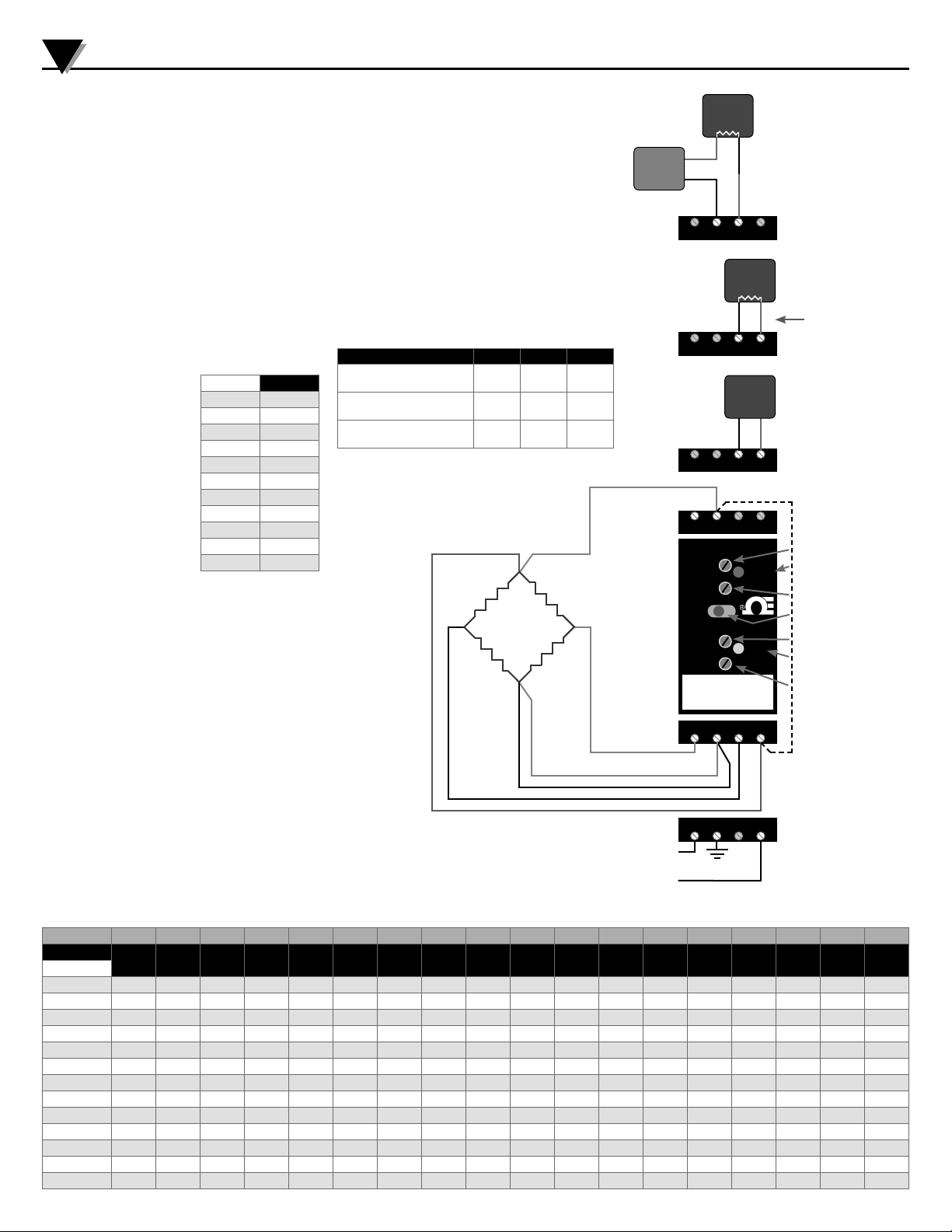
Electrical Connections
Check white model/serial number label for module operating voltage
to make sure it matches available power.
WARNING! All wiring must be performed by a qualified electrician or
instrumentation engineer. See diagram at right for terminal designations and wiring examples.
Avoid shock hazards! Turn signal input, output, and power off before
connecting or disconnecting wiring. Connect power last.
Module Power Terminals
When using DC power, either polarity is acceptable, but for consistency with similar API products, positive (+) can be wired to terminal
13 and negative (–) can be wired to terminal 16. Connect I/O wiring
before power wiring.
Excitation Switch A
10 V
9 V
8 V
7 V
6 V
5 V
4 V
3 V
2 V
1 V
0 V
A
9
8
7
6
5
4
3
2
1
0
Signal Input Terminals
Refer to strain gauge manufacturer’s data sheet for wire colorcoding. Polarity must be observed when connecting inputs.
CAUTION: Never short the excitation leads together. This will cause
internal damage to the module.
A five- or six-lead bridge has one or two sense leads respectively.
Sense leads allow the DMD4059 to compensate for leadwire resistance effects. Connect the sense leads if used. Polarity must be
observed.
If no sense lead is used, jumper sense (+) terminal 6 and excitation
(+) 12.
Final trim adjustment should be done after all connections are made.
Signal Output Terminals
Polarity must be observed when connecting the signal output.
If your device accepts a current input, determine if it provides power
to the current loop or if it must be powered by the DMD4059 module.
Use a multi-meter to check for voltage at the device's input terminals. Typical voltage may be 9-24 VDC.
Device Connected to Output Terminal Terminal Switch E
(+)
V
I
I
Voltage input
Passive mA (current) input.
Module provides loop power
mA (current) input device that
provides loop power.
3 (–) 4 (+)
(+20 V)
3 (–) 4
2 (–) 3
Sensor shield wire
(if equipped) should be
grounded at one end only
Sense +
(if used)
Exc. +
V
EX +
Sig.
Strain
–
Gauge
Sig.
V0 +V0 –
+
VEX –
Exc. –
Sense –
(if used)
Connect up to 4 strain gauges or load cells.
Colors shown are an example only.
See manufacturer's specifications for wiring
designations.
13 Power AC or DC +
14 Earth Ground
16 Power AC or DC –
Loop
Power
Source
OMEGA Engineering, Inc.
Excitation
4-20
mA
Input
Ri
+ –
+
–
– +
21 3 4
4-20
mA
Input
– +
21 34
Voltage
Input
– +
21 34
65 78
Output
Test Cal.
Test
Span
Zero
DMD4059
Strain Gauge to DC
Isolated Transmitter
LED
Input
LED
1091112
1413 15 16
Current Sinking
Output
Switch E
set to “I”
Current Sourcing
Output
Switch E
Ri
set to “I”
+20 V
Voltage Output
Switch E
set to “V”
Jumper 6 to 12 if sense
leads are not used
Excitation Voltage Trim
Variable Brightness Output
Indicator
Output Test Level Adjust
Push to Test Output
Output Span Calibration
Variable Brightness Input
Indicator
Output Zero Calibration
Output 0-1 V 0-2 V 0-4 V 1-5 V 0-5 V 0-8 V 2-10 V 0-10 V ±5 V ±10 V 0-2 mA 0-4 mA 0-8 mA 2-10 mA 0-10 mA 0-16 mA 4-20 mA 0-20 mA
Switches
Input
0-5 mV
0-10 mV
0-20 mV
0-25 mV
0-30 mV
0-40 mV
0-50 mV
0-100 mV
0-120 mV
0-200 mV
0-250 mV
0-300 mV
0-400 mV
BCDE BCDE BCDE BCDE BCDE BCDE BCDE BCDE BCDE BCDE BCDE BCDE BCDE BCDE BCDE BCDE BCDE BCDE
200V 208V 201V 206V 209V 202V 207V 203V 204V 205V 200I 208I 201I 206I 209I 202I 207I 203I
A00V A08V A01V A06V A09V A02V A07V A03V A04V A05V A00I A08I A01I A06I A09I A02I A07I A03I
300V 308V 301V 306V 309V 302V 307V 303V 304V 305V 300I 308I 301I 306I 309I 302I 307I 303I
600V 608V 601V 606V 609V 602V 607V 603V 604V 605V 600I 608I 601I 606I 609I 602I 607I 603I
E00V E08V E01V E06V E09V E02V E07V E03V E04V E05V E00I E08I E01I E06I E09I E02I E07I E03I
B00V B08V B01V B06V B09V B02V B07V B03V B04V B05V B00I B08I B01I B06I B09I B02I B07I B03I
000V 008V 001V 006V 009V 002V 007V 003V 004V 005V 000I 008I 001I 006I 009I 002I 007I 003I
800V 808V 801V 806V 809V 802V 807V 803V 804V 805V 800I 808I 801I 806I 809I 802I 807I 803I
F00V F08V F01V F06V F09V F02V F07V F03V F04V F05V F00I F08I F01I F06I F09I F02I F07I F03I
100V 108V 101V 106V 109V 102V 107V 103V 104V 105V 100I 108I 101I 106I 109I 102I 107I 103I
400V 408V 401V 406V 409V 402V 407V 403V 404V 405V 400I 408I 401I 406I 409I 402I 407I 403I
C00V C08V C01V C06V C09V C02V C07V C03V C04V C05V C00I C08I C01I C06I C09I C02I C07I C03I
900V 908V 901V 906V 909V 902V 907V 903V 904V 905V 900I 908I 901I 906I 909I 902I 907I 903I
Page 3

Calibration
The Zero, Span, and Excitation potentiometers are used to calibrate
the output. This calibration procedure does not account for offsets or
tare weights. If your system has an offset, tare weight or deadweight,
refer to the Offset Switch procedure.
To achieve optimum results, the system should be calibrated using
an accurate bridge simulator, pressure calibrator, or calibration
weights depending on the application.
1. Apply power to the module and allow a minimum 20 minute warm
up time.
2. Using an accurate voltmeter across terminals 10 and 12, adjust the
excitation voltage potentiometer for the exact voltage desired.
3. Provide an input to the module equal to zero or the minimum input
required for the application.
4. Using an accurate measurement device for the module output,
adjust the Zero potentiometer for the exact minimum output
signal desired. The Zero control should only be adjusted when the
input signal is at its minimum.
5. Set the input at maximum, and then adjust the Span pot for the
exact maximum output desired. The Span control should only be
adjusted when the input signal is at its maximum.
Using Offset Switch C
Offset switch C allows canceling or taring of non-zero deadweights
or other sensor offsets such as:
Compensate for tare weights or scale deadweight to get zero
output when a load is on the platform.
Compensate for low-output sensors (e.g., less than 1 mV/V) that
may have large zero offsets. Switch C can realign the zero control so it has enough range to produce the desired zero output.
Raising the offset to allow calibration of bipolar sensors such
as ±10 mV.
Lowering the offset to compensate for elevated input ranges
such as 10-20 mV.
1. Switch C does not interact with
any other switch and is the only
switch needed to correct zero
offsets. Its only purpose is to
adjust or cancel effects of the
low end of the input range not
corresponding nominally to 0 mV.
Setting this switch to “0” results
in no offset.
2. To RAISE the output zero, rotate
switch C from “1” thru “7”, until
the Zero control can be set for
your application.
3. To LOWER the output zero, rotate
switch C from “9” thru “F”, until
the Zero control can be set for
your application.
4. After all switches are set, repeat
the calibration procedure as
described above.
Offset
% of Span
105%
90%
75%
60%
45%
30%
15%
0%
–15%
–30%
–45%
–60%
–75%
–90%
–105%
Switch C
7
6
5
4
3
2
1
0
9
A
B
C
D
E
F
DMD4059 Series DC-DC Isolated Transmitter
Strain Gauge to DC Isolated Transmitter
DMD4059
Excitation Input OutputOffset
ABCDE
4
5
3
6
2
7
1
8
0
9
F
A
E
B
C
D
Connections
Term. #
3
4
6
9
10
11
12
13
16
Signal
Sig. Out –
Sig. Out +
Sense Lead
Sig. Input +
Exc. –
Sig. Input –
Exc. +
Power +
Power –
Output Test Function
When the test button is depressed it will drive the output with a
known good signal that can be used as a diagnostic aid during initial
start-up or troubleshooting. When released, the output will return
to normal.
The Test Cal. potentiometer can be used to set the test output to
the desired level. It is adjustable from 0 to 100% of the output span.
Press and hold the Test button and adjust the Test Cal. potentiometer
for the desired output level.
Installation Precautions
WARNING! Avoid shock hazards! Turn signal input, output, and
power off before connecting or disconnecting wiring, or removing
or installing module.
Mounting to a DIN Rail
The housing clips to a standard 35 mm DIN rail. The housing is IP40
rated and requires a protective panel or enclosure.
1. Tilt front of module downward and position against DIN rail.
2. Clip lower mount to bottom edge of DIN rail.
3. Push front of module upward until upper mount snaps into place.
Removal
1. Push up on the bottom back of the module.
2. Tilt front of module downward to release upper mount from top
edge of DIN rail.
3. The module can now be removed from the DIN rail.
4
5
3
6
2
7
1
8
0
9
F
A
E
B
C
D
1. Set Switch A for desired Excitation Voltage.
2. Set Switches B/C/D for desired Input / Output ranges.
3. Set Switch E for Voltage or Current as required.
4. Set Excitation / Zero / Span / Test Cal. Controls
Excitation Switch
Position
Voltage
A
10V
9
9V
8
8V
7
7V
6
6V
5
5V
4
4V
3
3V
2
2V
1
1V
0
0V
Output
V I
4
3
2
1
0
F
E
D
OUTPUT
Rotary Switches
0-1V
0-5V
1-5V
+/-5V
0-10V
+/-10V
4-20mA
5
6
B
C
INPUT
7
8
9
A
BCD
200
209
206
204
203
205
207
0-5 mV
BCD
A00
A09
A06
A04
A03
A05
A07
7
6
5
4
0-10 mV
0-20 mV
BCD
BCD
300
600
309
609
306
606
304
604
303
603
305
605
307
607
8
3
9
0
1
2
0-25 mV
BCD
E00
E09
E06
E04
E03
E05
E07
0-40 mV
0-30 mV
BCD
BCD
B00
000
B09
009
B06
006
B04
004
B03
003
B05
005
B07
007
For more Details
and Instructions see
Data Sheet
0-200 mV
0-100 mV
0-250 mV
0-50 mV
BCD
BCD
BCD
800
100
400
809
109
409
806
106
406
804
104
404
803
103
403
805
105
405
807
107
407
EXAMPLE:
0-30mV IN, 4-20mA OUT: CODE 0E7
Set switch “B” to 0; “C” to E; “D” to 7
Operation
Strain gauges and load cells are normally passive devices that
are commonly referred to as “bridges” due to their four-resistor
Wheatstone bridge configuration. These sensors require a precise
excitation source to produce an output that is directly proportional to
the load, pressure, etc. that is applied to the sensor.
The exact output of the sensor (measured in millivolts) is determined
by the sensitivity of the sensor (mV/V) and the excitation voltage
applied.
An additional input, the sense lead, monitors the voltage drop in the
sensor leads and automatically compensates the excitation voltage
at the module in order to maintain a constant excitation voltage at
the sensor.
The DMD4059 provides the excitation voltage to the sensors and
receives the resulting millivolt signal in return. This input signal is
filtered and amplified, then offset, if required, and passed to the
output stage. Depending on the output configuration selected, a DC
voltage or current output is generated.
The green input LED provides a visual indication that a signal is being
sensed by the input circuitry of the module. It also indicates the input
signal strength by changing in intensity as the process changes from
minimum to maximum.
If the LED fails to illuminate, or fails to change in intensity as the
process changes, check the module power or signal input wiring.
Note that it may be difficult to see the LEDs under bright lighting
conditions.
The red output LED provides a visual indication that the output signal
is functioning. It becomes brighter as the input and the corresponding
output change from minimum to maximum.
For current outputs, the red LED will only light if the output loop
current path is complete. For either current or voltage outputs,
failure to illuminate or a failure to change in intensity as the process
changes may indicate a problem with the module power or signal
output wiring.
3
Diagnostic Voltage Measurements
Using a meter with at least 10 megaohm input impedance, measure the voltage coming from the strain gauge at the locations shown.
Sensitivity is measured in mV/V.
Positive
Meter Lead
Negative
Meter Lead
Meter Reading
No pressure/load
Meter Reading
Full pressure/load
+ Exc. – Exc. Excitation Voltage Excitation Voltage
+ Sig. – Exc. + ½ Excitation Voltage ½ Excitation Voltage + (½ x Excitation Voltage x Sensitivity)
– Sig. – Exc. + ½ Excitation Voltage ½ Excitation Voltage – (½ x Excitation Voltage x Sensitivity)
+ Sig. – Sig. Zero Volts Excitation Voltage x Sensitivity
Page 4

Servicing Europe:
Benelux: Postbus 8034, 1180 LA Amstelveen, The Netherlands
OMEGAnet
www.omega.com info@omega.com
USA: One Omega Drive, Box 4047
ISO 9001 Certified Stamford CT 06907-0047
Canada: 976 Bergar
For immediate technical or application assistance:
USA and Canada: Sales Service: 1-800-826-6342 / 1-800-TC-OMEGA
Mexico: En Espan˜ ol: (001) 203-359-7803 e-mail:espanol@omega.com
FAX: (001) 203-359-7807 info@omega.com.mx
It is the policy of OMEGA to comply with all worldwide safety and EMC/EMI regulations that apply. OMEGA is constantly pursuing certification of its products to the
European New Approach Directives. OMEGA will add the CE mark to every appropriate device upon certification.
The information contained in this document is believed to be correct, but OMEGA Engineering, Inc. accepts no liability for any errors it contains, and reserves the right to alter specifications without
notice. WARNING: These products are not designed for use in, and should not be used for, human applications.
®
Online Service Internet e-mail
Servicing North America:
Tel: (203) 359-1660 FAX: (203) 359-7700
e-mail: info@omega.com
Laval (Quebec) H7L 5A1, Canada
Tel: (514) 856-6928 FAX: (514) 856-6886
e-mail: info@omega.ca
®
Customer Service: 1-800-622-2378 / 1-800-622-BEST
Engineering Service: 1-800-872-9436 / 1-800-USA-WHEN
TELEX: 996404 EASYLINK: 62968934 CABLE: OMEGA
®
Toll Free in Benelux: 0800 0993344
Czech Republic: Frystatska 184, 733 01 Karviná, Czech Republic
Tel: +420 (0)59 6311899 FAX: +420 (0)59 6311114
Toll Free: 0800-1-66342 e-mail: info@omegashop.cz
France: 11, rue Jacques Cartier, 78280 Guyancourt, France
e-mail: sales@omega.fr
Germany/Austria: Daimlerstrasse 26, D-75392 Deckenpfronn, Germany
e-mail: info@omega.de
United Kingdom: One Omega Drive, River Bend Technology Centre
ISO 9002 Certified Northbank, Irlam, Manchester
®
M44 5BD United Kingdom
Toll Free in United Kingdom: 0800-488-488
e-mail: sales@omega.co.uk
Tel: +31 (0)20 3472121 FAX: +31 (0)20 6434643
e-mail: sales@omegaeng.nl
Tel: +33 (0)1 61 37 2900 FAX: +33 (0)1 30 57 5427
Toll Free in France: 0800 466 342
Tel: +49 (0)7056 9398-0 FAX: +49 (0)7056 9398-29
Toll Free in Germany: 0800 639 7678
Tel: +44 (0)161 777 6611
FAX: +44 (0)161 777 6622
WARRANTY/DISCLAIMER
OMEGA ENGINEERING, INC. warrants this unit to be free of defects in materials and workmanship for a period of 13 months from date of purchase.
OMEGA’s WARRANTY adds an additional one (1) month grace period to the normal one (1) year product warranty to cover handling and shipping
time. This ensures that OMEGA’s customers receive maximum coverage on each product.
If the unit malfunctions, it must be returned to the factory for evaluation. OMEGA’s Customer Service Department will issue an Authorized Return (AR)
number immediately upon phone or written request. Upon examination by OMEGA, if the unit is found to be defective, it will be repaired or replaced
at no charge. OMEGA’s WARRANTY does not apply to defects resulting from any action of the purchaser, including but not limited to mishandling,
improper interfacing, operation outside of design limits, improper repair, or unauthorized modification. This WARRANTY is VOID if the unit shows
evidence of having been tampered with or shows evidence of having been damaged as a result of excessive corrosion; or current, heat, moisture or
vibration; improper specification; misapplication; misuse or other operating conditions outside of OMEGA’s control. Components which wear are not
warranted, including but not limited to contact points, fuses, and triacs.
OMEGA is pleased to offer suggestions on the use of its various products. However, OMEGA neither assumes responsibility for any omissions or errors
nor assumes liability for any damages that result from the use of its products in accordance with information provided by OMEGA, either verbal or
written. OMEGA warrants only that the parts manufactured by it will be as specified and free of defects. OMEGA MAKES NO OTHER WARRANTIES OR
REPRESENTATIONS OF ANY KIND WHATSOEVER, EXPRESS OR IMPLIED, EXCEPT THAT OF TITLE, AND ALL IMPLIED WARRANTIES INCLUDING ANY
WARRANTY OF MERCHANTABILITY AND FITNESS FOR A PARTICULAR PURPOSE ARE HEREBY DISCLAIMED. LIMITATION OF LIABILITY: The remedies
of purchaser set forth herein are exclusive, and the total liability of OMEGA with respect to this order, whether based on contract, warranty, negligence,
indemnification, strict liability or otherwise, shall not exceed the purchase price of the component upon which liability is based. In no event shall OMEGA be
liable for consequential, incidental or special damages.
CONDITIONS: Equipment sold by OMEGA is not intended to be used, nor shall it be used: (1) as a “Basic Component” under 10 CFR 21 (NRC), used
in or with any nuclear installation or activity; or (2) in medical applications or used on humans. Should any Product(s) be used in or with any nuclear
installation or activity, medical application, used on humans, or misused in any way, OMEGA assumes no responsibility as set forth in our basic
WARRANTY / DISCLAIMER language, and, additionally, purchaser will indemnify OMEGA and hold OMEGA harmless from any liability or damage
whatsoever arising out of the use of the Product(s) in such a manner.
Direct all warranty and repair requests/inquiries to the OMEGA Customer Service Department. BEFORE RETURNING ANY PRODUCT(S) TO
OMEGA, PURCHASER MUST OBTAIN AN AUTHORIZED RETURN (AR) NUMBER FROM OMEGA’S CUSTOMER SERVICE DEPARTMENT (IN
ORDER TO AVOID PROCESSING DELAYS). The assigned AR number should then be marked on the outside of the return package and on any
correspondence.
The purchaser is responsible for shipping charges, freight, insurance and proper packaging to prevent breakage in transit.
PATENT NOTICE: U. S. Pat. No. 6,074,089; 5,465,838 / Canada 2,228,333; 2,116,055 / UK GB 2,321,712 / Holland 1008153 / Israel 123052 / France
2 762 908 / EPO 0614194. Other patents pending.
FOR WARRANTY RETURNS, please have the following information
available BEFORE contacting OMEGA:
1. Purchase Order number under which the product was PURCHASED,
2. Model and serial number of the product under warranty, and
3. Repair instructions and/or specific problems relative to the product.
OMEGA’s policy is to make running changes, not model changes, whenever an improvement is possible. This affords our customers the latest in technology and
engineering.
OMEGA is a registered trademark of OMEGA ENGINEERING, INC.
© Copyright 2004 OMEGA ENGINEERING, INC. All rights reserved. This document may not be copied, photocopied, reproduced, translated, or reduced to any electronic
medium or machine-readable form, in whole or in part, without the prior written consent of OMEGA ENGINEERING, INC.
FOR NON-WARRANTY REPAIRS,
consult OMEGA for current repair charges.
Have the following information available BEFORE contacting OMEGA:
1. Purchase Order number to cover the COST of the repair,
2. Model and serial number of the product, and
3. Repair instructions and/or specific problems relative to the product.
M-5000/1110
RETURN REQUESTS / INQUIRIES
 Loading...