

Shm
on line at
(Wj
bvww.omega.com
e-mai/;
DMD-22
lo-
CHANNEL STRAIN METER
info@umega.
corn

OMEGAnet@
USA:
IS0
9001 Certified
Canada:
USA
and Canada:
On-Line Service
www .omega.com
Internet e-mail
info@omega.com
Servicing North America:
One
Omega Drive, P.O. Box 4047
Stamford CT 06907-0047
TEL: (203) 359-1660
e-mail: info@omega.com
976 Bergar
5Al
Lavai
(Quebec)
TEL: (514) 856-6928 FAX: (514) 856-6886
e-mail:
info@omega.ca
H7L
FAX: (203) 359-7700
For immediate technical or application assistance:
l-800-TC-OMEGAa
/
Sales Service:
Customer Service: l-800-622-2378
Engineering Service: l-800-872-9436
TELEX: 996404 EASYLINK: 62968934 CABLE: OMEGA
l-800-826-6342
/
l-800-622-BEST
l-800-USA-WHEN@
/
f
Mexico:
Benelux:
Czech Republic:
France:
Germany/Austria:
United Kingdom:
IS0
9002
Certified
Espaiiol: (001)
En
FAX: (001) 203-359-7807
203-359-7803
e-mail:
Servicing Europe:
Postbus
TEL:
Toil Free in Benelux: 0800 0993344
e-mail:
Rude
TEL:
Toll Free: 0800-l-66342
9, rue
TEL:
Toll Free in France: 0800-4-06342
e-mail:
Daimlerstrasse 26, D-75392 Deckenpfronn, Germany
TEL:
Toll Free in Germany: 0800 639 7678
e-mail:
One Omega Drive, River Bend Technology Centre
Northbank, Irlam, Manchester
M44
TEL:
Toll Free in United Kingdom:
e-mail:
8034,118O
(0)20
+31
nl@omega.com
armady
(0)69
+420
Denis
(0)130
+33
france@omega.com
(0)7059
+49
germany@omega.com
SEX
United Kingdom
(0)161777
+44
sales@omega.co.uk
LA Amstelveen, The Netherlands
6418405
1868,733 01
6311899
Papin, 78190 Trappes
621400
9398-O
6611
Karvina
8
0800-488-488
FAX:
+31(0)20
FAX:
+420
e-mail: czech@omega.com
FAX:
+33
FAX:
+49
FAX:
+44
espanol@omega.com
info@omega.com.mx
6434643
(0)69
6311114
(0)130
699 120
(0)7056
9398-29
(0)161777
6622
It is the policy of OMEGA to comply with all worldwide safety and
apply. OMEGA is constantly pursuing certification of its products to the European New Approach
Directives. OMEGA will add the CE mark to every appropriate device upon certification.
The information contained in this document is believed to be correct, but OMEGA Engineering, Inc. accepts
no liability for any errors it contains, and reserves the right to alter specifications without notice.
WARNING: These products are not designed for use in, and should not be used for, patient-connected applications.
EMC/EMI
regulations that
TABLE OF CONTENTS
SECTION
SECTION 1
SECTION 2
SECTION 3
3.1
3.2
SECTION 4
4.1
4.2
4.3
General Description
Unpacking
Parts
Front
Rear
Wiring
Full Bridge Configuration
Half Bridge Configuration
Quarter Bridge Configuration
PAGE
1
2
2
2
4
5
5
5
4.4
4.5
SECTION
5.1
5.2
SECTION 6
SECTION 7
5
Other Configurations
Internal Circuit
Operation
Introduction to operation
Procedure to use
Rechargeable Batteries Replacement
Specifications
a
a
12
12
13
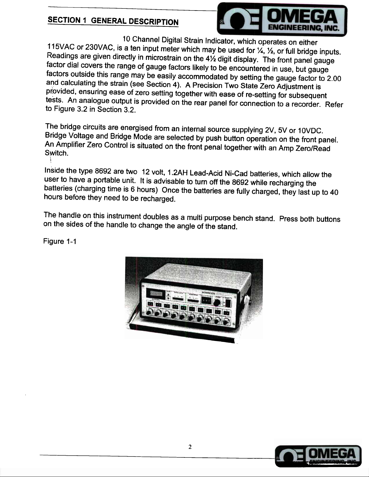
10 Channel Digital Strain Indicator, which operates on either
1/2,
or’full bridge inputs.
‘A,
SVAC
11
230VAC,
or
is a ten input meter which may be used for
Readings are given directly in microstrain on the 4% digit display. The front panel gauge
factor dial covers the range of gauge factors likely to be encountered in use, but gauge
factors outside this range may be easily accommodated by setting the gauge factor to 2.00
and calculating the strain (see Section 4). A Precision Two State Zero Adjustment is
provided, ensuring ease of zero setting together with ease of re-setting for subsequent
tests. An analogue output is provided on the rear panel for connection to a recorder. Refer
to Figure 3.2 in Section 3.2.
5V
2V,
The bridge circuits are energised from an internal source supplying
1OVDC.
or
Bridge Voltage and Bridge Mode are selected by push button operation on the front panel.
An Amplifier Zero Control is situated on the front penal together with an Amp Zero/Read
Switch.
Inside
user to have a portable unit.
the type 6692 are two 12 volt,
It is advisable to turn off the 6692 while recharging the
1.2AH
Lead-Acid Ni-Cad batteries, which allow the
batteries (charging time is 6 hours) Once the batteries are fully charged, they last up to 40
hours before they need to be recharged.
The handle on this instrument doubles as a multi purpose bench stand. Press both buttons
on the sides of the handle to change the angle of the stand.
Figure l-l
2

Operating Instructions
SECTION 2 UNPACKING
Remove the packing list and verify that all equipment has been received.
Upon receipt of shipment, inspect the container and equipment for any signs of damage.
Take particular note of any evidence of rough handling in transit.
immediately to the shipping agent/Courier.
i’
Report any damage
Note: The carrier will not honour any claims unless all shipping material is saved for their
examination. After removing and examining contents, save packing material and carton in
the event of a query.
Make sure the following items are in the shipping box:
DESCRIPTION
I
1
1
1
Digital Strain Indicator with integral battery pack and
charger.
Power Cord
Operators Manual
3
SECTION 3 PARTS
3.1
Front of the Strain Meter
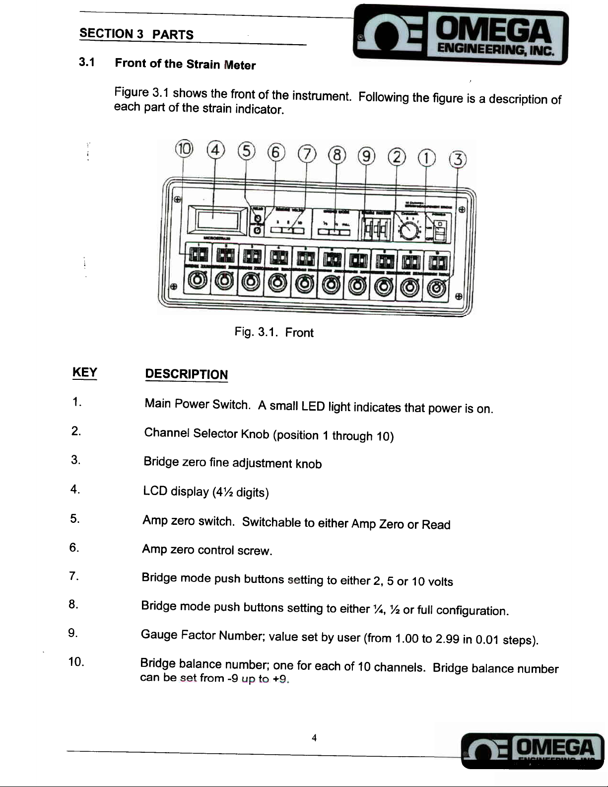
Figure 3.1 shows the front of the instrument. Following the figure is a description of
each part of the strain indicator.
Fig. 3.1. Front
KEY
1.
2.
3.
4.
5.
6.
7.
a.
9.
Main Power Switch. A small LED light indicates that power is on.
Channel Selector Knob (position 1 through 10)
Bridge zero fine adjustment knob
LCD display (4% digits)
Amp zero switch. Switchable to either Amp Zero or Read
Amp zero control screw.
Bridge mode push buttons setting to either 2, 5 or 10 volts
Bridge mode push buttons setting to either
%
or full configuration.
%,
Gauge Factor Number; value set by user (from 1 .OO to 2.99 in 0.01 steps).
IO.
IO
Bridge balance number; one for each of
can be set from -9 up to
+9.
4
channels. Bridge balance number

3.2
REAR OF INSTRUMENT
Figure 3.2 shows the rear
Following the figure is a description of each
part of the strain indicator.
Fig. 3.2. Rear
KEY
DESCRIPTION
1.
2.
3.
4.
5.
Power Cord Socket
Fuse (500mA anti surge type)
Voltage Selector Switch
(115V/23OV)
Analogue output connector (BNC Connection)
Interface Connector capable of hooking up 10 Strain Gauges (one circuit per
channel).
5

SECTION 4. WIRING
1.
Make sure the voltage Selector Switch (fig. 3.2,
for your country.
2.
Connect the strain gauges to be measured to the terminals at the rear of the
instrument as shown in figures 4.1 through 4.5 and as described below.
4.3
FULL BRIDGE CONFIGURATION
Positive supply to PI
Negative supply to P2
Negative signal to
,
Positive signal to S2
No connections to P3 and P4
Minimum gauge resistance is 120
ohms.
Sl
#3)
-SIGNAL
c
FULL
is set to the appropriate voltage
I
4
BRIDGE
---_.
St
Dr
FfCCIRs
OR
S
mV/V
_.
Pa
J’r
4-1
TRANSDUCER
4
Sa
4.2
HALF BRIDGE CONFIGURATION
Positive supply to PI
Negative supply to P2
Strain Gauge junction to
Jumper PI to P3 and P2 to P4
Minimum gauge resistance is
Sl
80
D.
ohms
-EXCfTATION
&
S
S,
+EXCITATtON
r.
S
S
Sr
6

4.3
QUARTER BRIDGE CONFIGURATION
(Single gauge, three wire connection)
Strain gauge terminal 1 to PI
Strain gauge terminal 2 to
i’
,
Strain gauge terminal 2 to
Jumper PI to P3
Jumper P2 to P4
Dl
Use
1
‘I
D2 for 350 ohm gauges
4.4
For two wire quarter bridge configuration using 120 or 350 ohm gauges, connect the active
gauge between PI and
or D2 to
Refer to figure 4.4.
OTHER CONFIGURATIONS
for 120 ohm gauges or
Sl.
Jumper PI to P3, P2 to P4 and
Sl
fro 350 ohm gauges. Select
Sl
Dl or
02
‘A
bridge mode for direct reading in microstrain.
TYiREE
FICURG
WIRE
Dl
to
QUARTER BRIDGE
Sl
/
4-3
for 120 ohm gauges
For other resistance values, use the half bridge arrangement with an external resistor (RI).
Sl
In this case, connect the active gauge between terminals
resistor between
bridge mode for direct reading in microstrain. Refer to figure 4.5
Sl
and P2. Jumper
Da
0
Pl to P3 and P2 to P4 on the rear panel. Select
%
DI
J3
St
P,
Pl and
8
SZ
0
and the external
I!
?p
4
120
-
_.
%I’
Fig. 4.4. Two-wire quarter bridge
7

0 0
0
/
4.5
INTERNAL CIRCUIT
PI = + Excitation
P2 =
Sl
S2 = + Signal
P3 =
P4 =
Dl = 120 ohm,
D
w
IU
Fig. 4.5. Quarter bridge other than 120 ohms or 350 ohms
Excitation
-
-
Signal
=
%
bridge completion resistor
%
bridge completion resistor
Fig. 4.6. Internal Circuit
%
bridge completion resistor
D2 = 350 ohm,
%
bridge completion resistor
8

SECTION 5 OPERATION
5.1
1.
INTRODUCTION TO OPERATION
An output of approximately 2 volts full scale is available at the rear BNC socket of
the instrument, suitable for the connection of an oscilloscope or other high
impedance recording of display device. The available dynamic response of this
output extends beyond 20 KHz. This output may also be used to supply a Recorder
i’
provided the recorder is fitted with a suitable amplifier containing a gain control
i
enabling the signal to be set to a specific value of strain for a given trace width.
2.
For optimum accuracy, the indicator should be left on for approximately ten minutes
before final adjustment of zero is made.
of time, without being able to restore the original zero conditions of the specimen or
structure, then the reading on the zero dials should be noted, so that the indicator
may be set to the same zero condition when re connecting. Record reading
I
i
here.
3.
The gauge factor control should be set to the value appropriate to the gauges in
use.
the dial to 2.00 and correct the strain readings by simple arithmetic proportion.
If tests are being conducted over a period
If gauges are used whose gauge factor is outside the provided range, then
set
4.
Hook up a load cell or pressure transducer to display in engineering units of your
choice.
Set the gauge factor on the Type 6692 per the following formula:
GF
(mv/“)
=
1000
DX B
GF = Gauge factor setting on the instrument.
mVN = Rated output of the Transducer/Sensitivity.
If the sensor does not state the rated output in the
mV
output by the excitation voltage to get the
D=
Desired display at full scale output. Note the display does not have a decimal
mVN format, divide the full scale
mVN output.
point.
B = Bridge selection
Full Bridge = 1
Half Bridge =
Quarter Bridge =
%
‘%
9

5.
#2).
Se lect the channel desired using the channel selector knob (fig. 3.1
Make sure
the strain gauge is connected at the rear of the instru ment, to the corresponding
panel.
#5
Set front panel switch fig. 3.1
screw (fig. 3.1
#6)
until you see 0000 on the digital display, then set switch to the
to Amp Zero then set and adjust adjacent zero
“Read ” position and adjust for zero on the display by using the appropriate Coarse
Zero control (fig. 3.1
#IO)
and the Bridge Zero Knob (fig. 3.1
#3)
on the front panel.
When you have zeroed the instrument, lock the control in place using the black out
knob.
If further readings are to be taken at a later date, record the setting of the
Bridge Balance Number and the Bridge Zero Dial.
Record value here:
(Bridge Balance Number)
(
Bridge Zero)
6.
7.
a.
b.
C.
e.
f.
For dynam ic measurements, the signal available at the BNC socket on the rear
pane l (fig. 3.2
socket is
#4)
may be connected to an amplifier or a recorder. The output at this
f
2 volts which is equivalent to
&20,000
m icrostrain. The frequency
response is DC to 20 KHz.
To use the Type 6692 to monitor Strain Gauge Transducers, whose calibration is
known in ter ms of millivolts per volt.
Set volts to 10 volts
Set bridge mode to
Set the gage factor dial (fig. 3.1
Set front panel switch to READ (fig. 3.1
%
bridge
#5)
and ad just ZERO screw (fig. 3.1
#6).
#5)
and ad just zero control until zero is
shown on the Digital Volt Me ter.
App ly load to Transducer and note reading on the display (fig. 3.1
#4)
2,000
microstrain on the display indicates a signal of 1 .O millivolt per volt.
h.
Note that once the amplifier zero screw has been adjusted in step 5, it will only need
occasional re adjusting.
The following diagra ms give details of Bridge mode and gauge factor setting.
10

.._-____
.--.
..--
._
:c
---
W#
04-
-2.
ACTIVX
STMINS
‘OIlAt
coypI)22SiON.
2 IN
eRlDCX
W.L
.-. _-.
-.-.
-
-.-
,-..-
..
Bridge Mode
YONmNNC
4
+
2
CCNcICURATlON
-.-
-------St
-_-_
--.
.-
T’N.OION
__..__..
WU
.
-..
_.
&
Gague Factor
--.
“-e
- -
Se tting
. .
---_____.__.-_-._
.__
%
11
W I-
W#
.__..
-
m-
---
W#
WI-
W#(lM)
8

5.2
PROCEDURE
TO USE
1.
2.
3.
4..
5.
Connect strain gauges in accordance with section 4.
#8)
Select the correct bridge mode (fig. 3.1
Select the bridge excitation voltage (fig. 3.1
&3).
Set the bridge zero (fig. 3.1
#2
Refer to step 5 in section 5.1.
on the front panel.
#7)
required on the front panel.
Set the gauge factor dial to the gauge factor for the gauges in use, apply strain and
note reading on the LCD (fig. 3.1,
instrument is
*I9999
microstrain and therefore no range switch is required.
##4)
on the front panel.
Note that the range of the
SECTION 6 RECHARGEABLE BATTERIES REPLACEMENT
To replace batteries:
1.
2.
Turn off the type 6692, and unplug.
Unscrew the 4 screws from the top cover and remove top cover.
3.
4.
5.
6.
Unplug the 4 leads to the batteries.
Unscrew the 4 screws holding the battery clamp and remove clamp.
1.2AH
12V,
Remove old batteries and replace with fresh
lead acid rechargeable
batteries.
Follow steps 1 through 4 in reverse order.
12

SECTION 7. SPECIFICATIONS
Channels
Range
Linearity
;
Gauge resistance
10
f
19999 Microstrain
0.02% full scale
x
bridge: 120 or 350 ohms
x
bridge: at least 80 ohms
Full bridge: at least 120 ohms
gauge factor range
Bridge voltage
Bridge modes
Bridge zero
1 .OO to 2.99 in 0.01 steps
2VDC,
x,
SVDC
‘/z
or full bridge
IOVDC
or
Coarse adjustment is in 9 overlapping steps up to 10,000
microstrains,
f
2% resistance imbalance is covered. Fine
adjustment is by a locking 10 turn front panel control with
a range of 1 to 700 microstrain.
Zero drift
Gain drift
Input impedance
Gauge connections
Less than 0.5
Less than
1000
megohm
Screw terminals are at the rear and provide for
microstrain/ “C
O.O05%/ “C
full bridge connections.
Analogue output
Frequency response
Power
f
2VDC. Equivalent to
DC to 20k Hz
115/23OVAC,
(2)
12V,
50/60Hz.
1.2AH
Lead-Acid rechargeable batteries built
f
20000 microstrain
Slide switch at rear. Battery: two
in. Full charge of 40 hours approximately.
Weight
Dimensions
(less handle)
15.4 pounds (7 Kg)
14.5” L x 6.00 ” H x 11
.a”
D
(370 x 150 x 300mm) refer to fig. 7.1
W
x,
or
13

1
(I4.-0’,
Fig. 7.1
Dimensions

f
OMEGA ENGINEERING, INC.
period of 13
months
from date of purchase.
grace period to the normal
ensures that
OMEGA ’s
customers receive maximum coverage on each product.
If the unit malfunctions, it must be returned to the factory for evaluation.
warrants this unit
to be free of defects
OMEGA ’s WARRANTY
one (1) year product warranty
in
materials and workmanship for a
(1)
adds an additional one
month
to cover handling and shipping time. This
OMEGA ’s
Customer Service
Department will issue an Authorized Return (AR) number immediately upon phone or written request.
Upon examination by OMEGA, if the unit is found to be defective, it will be repaired or replaced at no
charge. OMEGA’s WARRANTY does not apply to defects resulting from any action of the purchaser,
including but not limited to mishandling, improper interfacing, operation outside of design limits,
improper repair, or unauthorized modification.
having
been tampered with or shows evidence of having been damaged as a result of excessive corrosion;
This WARRANTY is VOID if the unit shows evidence of
or current, heat, moisture or vibration; improper specification; misapplication; misuse or other operating
conditions outside of OMEGA ’s control. Components which wear are not warranted, including but not
limited to contact points, fuses, and
triacs.
OMEGA is pleased to offer suggestions on the use of its various products. However,
OMEGA neither assumes responsibility for any omissions or errors nor assumes liability for any
damages that result from the use of its products in accordance with information provided by
pa-
OMEGA, either verbal or written. OMEGA warrants only that the
as specified and free of defects.
REPRESENTATIONS OF ANY
AND AU
IMPUED
WARRANTlES
KlND
WHATSOEVER, EXPRESS OR
INCLUDING ANY WARRANTY OF
OMEGA MAKES NO OTHER WARRANTIES OR
manufactured by it will be
IMWED,
EXCEPT THAT OF
MERCHANTABlLlTY
TlTLE,
AND
FITNESS FOR A PARTICULAR PURPOSE ARE HEREBY DISCLAIMED. LIMITATION OF
LlABlLlTYz
The remedies of purchaser set forth herein are exclusive, and the total liability of
OMEGA with respect to this order, whether based on contract, warranty, negligence,
indemnification, strict liability or otherwise, shall not exceed the purchase price of the
component upon which liability is based. In no event shall OMEGA be liable for
consequential, incidental or special damages.
(I)
CONDITIONS: Equipment sold by OMEGA is not intended to be used, nor shall it be used:
as a “Basic
Component” under 10 CFR 21 (NRC), used in or with any nuclear installation or activity; or (2) in medical
applications or used on humans. Should any Product(s) be used in or with any nuclear installation or
activity, medical application, used on humans, or misused in any way, OMEGA assumes no responsibility
as set forth in our basic WARRANTY/DISCLAIMER language, and, additionally, purchaser will indemnify
OMEGA and hold OMEGA harmless from any liability or damage whatsoever arising out of the use of the
Product(s) in such a manner.
RETURN REQUESTS/INQUIRIES
Direct all warranty and repair requests/inquiries to the OMEGA Customer Service Department. BEFORE
RETURNING ANY PRODUCT(S) TO OMEGA, PURCHASER MUST OBTAIN AN AUTHORIZED RETURN
(AR) NUMBER FROM OMEGA ’S CUSTOMER SERVICE DEPARTMENT (IN ORDER TO AVOID
PROCESSING DELAYS). The assigned AR number should then be marked on the outside of the return
package and on any correspondence.
The purchaser is responsible for shipping charges, freight, insurance and proper packaging to prevent
breakage in transit.
WARRANTY
FOR
following information available
contacting OMEGA:
1.
Purchase Order number under which the product
was PURCHASED,
2.
Model and serial number of the product under
warranty, and
Repair instructions and/or specific problems
3.
relative to the product.
OMEGA’s
our customers the latest
OMEGA is a registered trademark of OMEGA ENGINEERING, INC.
0
Copyright 2000 OMEGA ENGINEERING, INC. All rights reserved. This document may not be copied, photocopied,
reproduced, translated, or reduced to any electronic medium or machine-readable form,
prior written consent of OMEGA ENGINEERING, INC.
policy is to make running changes, not model changes, whenever an improvement is possible. This affords
RETURNS, please have the
BEFORE
in technology and engineering.
NON-WARRANTY
FOR
for current repair charges. Have the following
information available BEFORE contacting OMEGA:
REPAIRS, consult OMEGA
Purchase Order number to cover the COST
of the repair,
Model and serial number of the product, and
Repair instructions and/or specific problems
relative to the product.
in
whole or in part, without the

I
Where Do
Find Everything I Need for
Process Measurement and Control?
OMEGA ...Of Course!
f
Shop on line af
www.omega.com
TEMPERATURE
&
IZ
Thermocouple, RTD
0 Wire: Thermocouple, RTD
0 Calibrators
0 Recorders, Controllers
0 Infrared Pyrometers
&
Ice Point References
Thermistor Probes, Connectors, Panels
&
Thermistor
&
Process Monitors
PRESSURE, STRAIN AND FORCE
&
0
Transducers
0 Load Cells
0 Displacement Transducers
0 Instrumentation
Strain Gages
&
Pressure Gages
&
Accessories
FLOW/LEVEL
&
0
Rotameters, Gas Mass Flowmeters
0 Air Velocity Indicators
Turbine/Paddlewheel Systems
0
&
Totalizers
0
Batch Controllers
Flow Computers
pH/CONDUCTIVITY
&
pH Electrodes, Testers
0
Benchtop/L.aboratory
0
0 Controllers, Calibrators, Simulators
&
Conductivity Equipment
pH
0
Industrial
Accessories
Meters
&
Pumps
DATA ACQUISITION
&
0
Data
Acquisition
0
Communications-Based Acquisition Systems
0
Plug-in Cards for Apple, IBM
0
Datalogging Systems
0
Recorders, Printers
Engineering Software
&
Compatibles
&
Plotters
&
Assemblies
HEATERS
0
Heating Cable
&
0
Cartridge
0
Immersion
0
Flexible Heaters
@’
Laboratory Heaters
Ship Heaters
&
Band Heaters
ENVIRONMENTAL
MONITORING AND CONTROL
&
Metering
Refractometers
Pumps
Air, Soil &Water Monitors
Industrial Water
pH,
Control
&
Tubing
Conductivity
Instrumentation
&
Wastewater Treatment
&
Dissolved Oxygen Instruments
M-1247/d/00
 Loading...