

Page 1
!DMD-21
Single Cha
nnel Digital Strain Indicator
I
I
Operator’s Manual
M1244/0991
Page 2
TABLE OF CONTENTS
DMD-21
SINGLE CHANNEL DIGITAL STRAIN INDICATOR
SECTION
SECTION 1
SECTION 2
SECTION 3
3.1 Front of the DMD-21
3.2 Rear of the DMD-21
SECTION 4
4.1 Full bridge configuration
4.2 Half bridge configuration
4.3 Quarter bridge configuration
4.4 Other configurations
GENERAL DESCRIPTION
UNPACKING
PARTS OF THE DMD-21
WIRING
PAGE
1
2
4.5 Internal circuit
SECTION 5
5.1 Introduction to operation
5.2 Procedure to use the DMD-21
SECTION 6
SECTION 7
SECTION 8
SECTION 9
OPERATION
RECHARGEABLE BATTERIES REPLACEMENT
ACCESSORIES
SPECIFICATIONS
&
BRIDGE MODE
GAGE FACTOR SETTING
8
8
11
11
11
12
13
i
Page 3
satisfactory
)
m onth
(I
13
for a period
period to tho normal one (1) year product warranty to cover handling and shipping time. This ensures that
customers
to the factory for evaluation.
immediately
it
w ill be
of having boen
current, heat, moisture or vibration; improper specification; misapplication; misuse or other operating
outside of OMEGA ’s control. Components which wear or which are damaged by misuse are not
These include contact points, fuses, and
repaired
months from date of purchase. OMEGA Warranty adds an additional one
of
rt?ceive
upon phone or
maximum coverage on each product. If the unit should malfunction, it must be returr
or
replaced at
ta m pered
Our Customer
written request.
no charge. However, this WARRANTY is VOID if the unit shows
with or shows evidence of being damaged as a result of excessive corrosion;
Service Department will issue an Authorized Return (AR)
Upon examination by OMEGA, if the unit is found to be defect
triacs.
serv
OMEGA warrants this unit to be free of defects in materials and workmanship and to give
grE
numt
evider
con&tic
warrants
(
There
are no warranties except as stated herein. There are no other warranties, expressed or implied,
but not limited to the implied warranties of merchantability and of fitness for a particular purpose,
INC.’
is
ENGINEERING,
not responsible for any damages or losses caused to other equipment, whether
indirect, incidental, special or consequential, which the purchaser may experience as a result of the
includi
OME<
dire,
installati
or use of the product. The buyer ’s sole remedy for any breach of this agreement by OMEGA ENGINEERIN
INC. or any
breach
of any Warranty by OMEGA ENGINEERING, INC. shall not exceed the purchase pri
paid by the purchaser to OMEGA ENGINEERING, INC. for the unit or units or equipment directly affect
by such
Every
ENGINEERING, INC.
liabilii
in the
Direct all warranty and repair requests/inquiries to the OMEGA ENGINEERING Customer Service
Call
FAX:
BEFORE RETURNING ANY PRODUCT(S) TO OMEGA, YOU MUST OBTAIN AN AUTHORIZED RETURN
NUMBER PROM OUR CUSTOMER SERVICE DEPARTMENT (IN ORDER TO AVOID PROCESSING
The
correspondonce.
brench.
precaution for accuracy has been taken in the preparation of this manual, however,
neither assumes responsibility for any omissions or errors that may appear nor
any
for
damages that result from the use of the products in accordance with the information contain
manuill.
Departme
toll
fret?
203-359-7607,
assignrId
in
AR number should then be marked on the outside of the return package and on a
the
USA:
1-800-622-2378,
FAX:
203-359-7811;
International: 203-359-166
OMEC
assun-
(1
DELAY
FOR
WAR R
following information available BEFORE contacting
OMEGA:
1.
P-0. number under which the product
was PURCHASED,
2.
Model
under
3.
Repair instructions and/or specific
problems
product.
OMEGA’s
get
OMEGA
@
any
Polk
the
latest
is
Copyright
manner,
in
ANTY
RETURNS, please have the
and serial number of the product
wirrranty, and
you
are having with the
running
is to make
111
technology and engineering.
retjistered
a
1991
cjither
trademark of OMEGA ENGINEERING, INC.
OMEGA ENGINEERING, INC. All rights reserved including illustrations.
wholly or
changes, not model changes, whenever an improvement is possible. That
any
purpose whatsoever without written permission from
for
pan
in
t
Printed in England
FOR
NON-WARRANTY
consult OMEGA for current repair/calibration
Have the following information available BEFO
1
contacting OMEGA-
Your
1.
the repair/calibration,
Model and serial number of product,
Repair instructions and/or specific
3’:
problems you are having with the
product.
P.O. number to cover the COST of
REPAIRS OR
way
Nothing in this
OMEGA
CALIBRATIC
our
manual
custom
maY
ENGINEERING,
be
charg
mploduc
Ir
Page 4
SECTION 1 GENERAL DESCRIPTION
OMEGA
The
either
DMD-21
115VAS
used for
directly in
panel gage
to be encountered in
maybe
easily
calculating the strain (see Section 4).
Zero Adjustment
together
output
with
is provided on the rear panci for connection to a
recorder.
The bridge circuits are
supplying
2V,
selected by
Amplifier Zero
mg
with an
Zero/Read Switch.
Inside the DMD-21 are two (2) 8.4 Volt,
Digital
or
i,
3,
microscrains
factor
dial covers
accommodat,ld
Strain Indicator, which
23OVAC,
fulL
or
is a single input meter which may be
bridge inputs.
44
on the
digit display.
the rsnge of gage factors likely
use,
but gage factors outside this range
by setting the
A Precision
is provided ensuring
ease of zero setting
ease of re-setting for subsequent tests. An analog
Refer to Figure 3-2 in Section 3.2.
5V
or
10MC.
push-bcxton
Control
energizec?
Bridge
operation on
is situated on the front panel together
from an intemai source
Vtiltage
the front panel.
1.2AH
which allow the user to have a portable unit.
batteries
the
to turn off
t.;e
DMD-21
while
recharging
ocerates
Readings
are
The front
gage factor to 2.00 and
.z_d
Bridge Mode are
Ni-Cad batteries
It is advisable
(charging
on
given
Two-State
in
time is 6 hours). Once the batteries are fully charged, they
last for up to 40 hours before they need to be recharged again.
The handle on the
DYD-21
doubles as a multi-position bench stand.
Press both buttons on the sides of the handle to change the angle
of the stand.
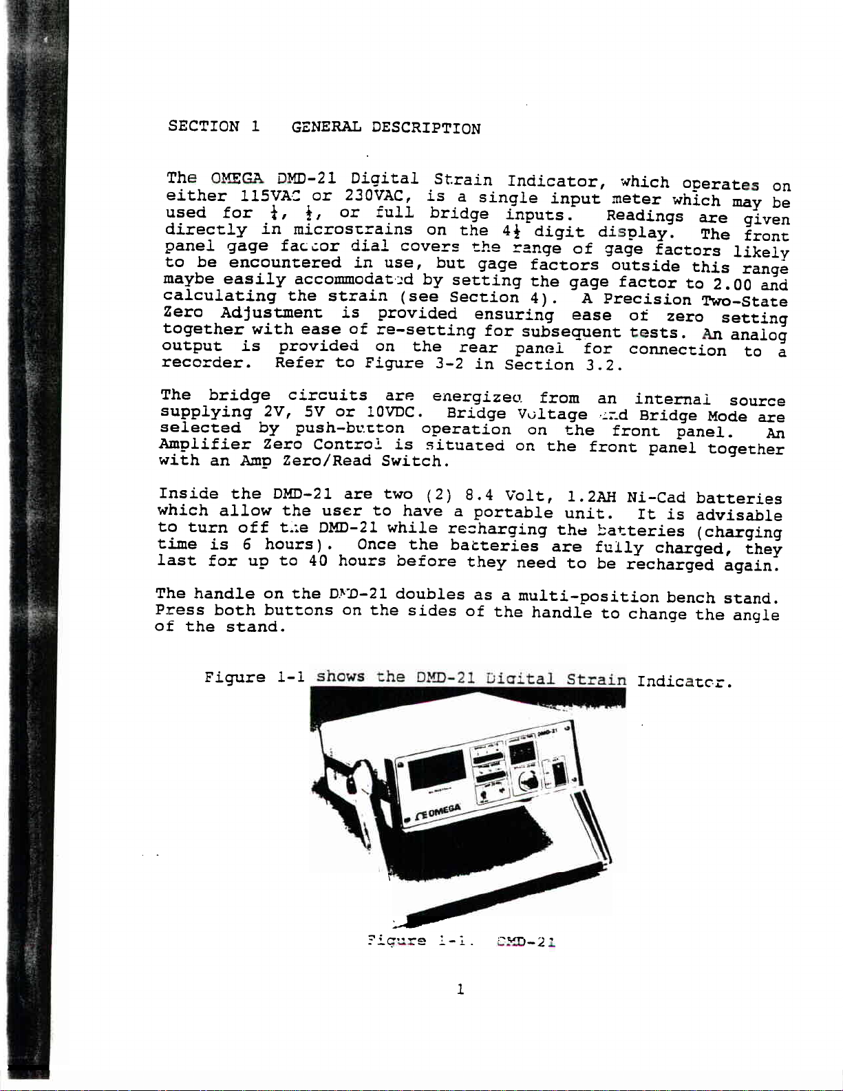
Figure
l-1
shows the DMD-21
Dioital
Strain
Indicator.
Page 5
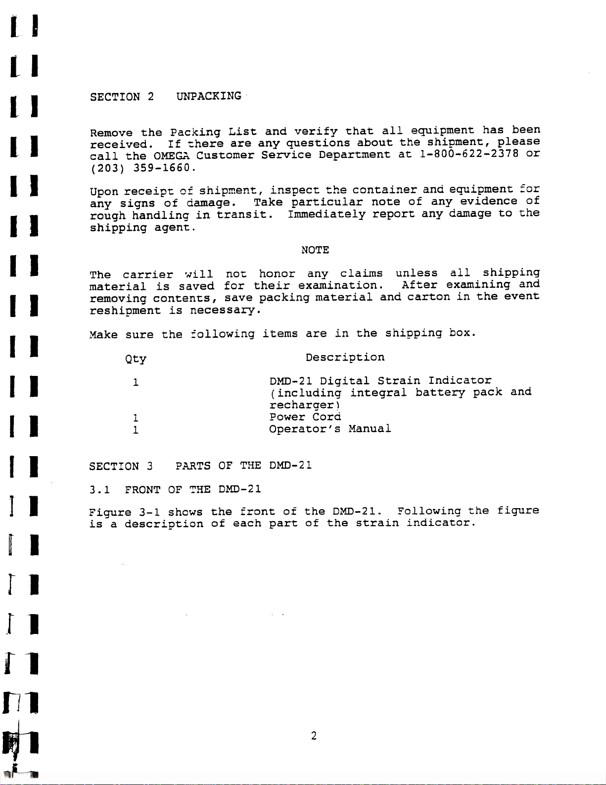
SECTION 2
UNPACKING
Remove the Packing List and verify that all equipment has been
received.
If there are any questions about the shipment, please
call the OMEGA Customer Service Department at l-800-622-2378 or
(203) 359-1660.
Upon receipt of shipment, inspect
any signs of damage.
rough handling in transit.
Take particular note of any evidence of
Immediately report any damage to the
the container and equipment for
shipping agent.
NOTE
The carrier
will not honor
any claims
material is saved for their examination.
save
removing contents,
packing material and carton in the event
unless
After examining and
all shipping
reshipment is necessary.
Make sure the following items are in the shipping box.
Q~Y
1
DMD-21 Digital Strain Indicator
Description
(including integral battery pack and
recharger)
1
1
SECTION 3
PARTS OF THE DMD-21
Power Cord
Operator's Manual
3.1 FRONT OF THE DMD-21
Figure 3-l shows the front of
is a description of each part
the
DIMD-21.
Following the
of the strain indicator.
2
figure
Page 6

:.
MICROSTRAIN
(
GAlJGp
FACTOR
ON
il
=i=
11EO MEC IA”
0
KEY
1
2
3
4
5
Figure 3-l.
Main Power Switch.
indicates that power is on.
Bridge Zero fine adjusting knob.
outer ring knob locks setting.
Amp Zero Control Screw.
Amp Zero Switch switchable to either
Amp Zero or Read.
Bridge Mode pushbuttons setting to either
4,
i,
READ
Front of the DMD-21
DESCRIPTION
A smail LED lit
The
or full configuration.
Bridge Volts pushbuttons setting to either
2, 5 or 10 volts.
.Gage
Factor Number;
Value set by user (from
1.00 to 2.99 in 0.01 steps).
8
LCD Display
(44
digits).
3
Page 7

3.2
REAR
OF TH E
DMD-21
Figure 3-2 shows
is a description
the rear of the DMD-21.
Following the figure
of each part of the strain indicator.
:f
,
7‘;
ed
,
Figure 3-2.
‘ 4
!
I
Rear of the DMD-21
-
I
KEY
1
2
3
4
5
6
DESCRIPTION
Fuse
(5OOmA
Voltage Selector Switch
anti-surge type)
(115V/23OV)
Analog Output Connector (BNC Connection)
Bridge Balance
interface Connector for strain gages
power
Cord Socket
4
Page 8

SECTION 4 WIRING
1.
Make sure the Voltage Selector Switch (Figure 3-2,
set to the appropriate voltage for your country.
%2)
is
2.
4.1
4.2
Connect the strain gages to be measured to the terminals at
the rear of the instrument as shown in Figures 4-l through
4-5
and as described below.
S,
pr
P,
FULL BRIDGE CONFIGURATION
‘.
Positive Supply to
Pl
0
Dr
Pz
P,
S,
D,
,a
PP
0 0
PP
Negative Supply to P2
Negative Signal to
Sl
Positive Signal to S2
No connections to P3 and P4
4-
Minimum gage resistance is
120 ohms
HALF BRIDGE CONFIGURATION
Positive Supply to
Pl
FULL BRIDGE OR
D,
Dz
FIGURE
S,
4
1
mV/V TRANSDUCER
P,
4
4
Negative Supply to P2
Strain Gage junction to
Pl
Jumper
to P3 and P2 to P4
Sl
Minimum gage resistance is 80 ohms
-EXCITATION
FIGURE 4-2
HALF BRIDGE
Page 9

4. 3
QUARTER
BRIDGE
CONFIGURATION
(Single
gage,
Strain Gage terminal 1 to
Strain
Gage
Strain Gage terminal 2 to
Pl
Juinper
to P3
three-wire connection)
Pl
terminal 2 to
Sl
Dl
Jumper P2 to P4
Dl
Use
D2
for 120 ohm
for 350 ohm gages
gages
or
4.4 OTHER CONFIGURATIONS
For other resistance values,
(Rl).
an external resistor
between terminals
and
Sl
to
P2.
Jumper
Dl
for 120 ohm gages.
Pl
and
Pl
to P3 and P2 to P4 on the rear panel.
In this case, connect the active gage
Sl
and the external resistor between
Refer to Figures 4-4 and 4-5.
I
or D2
FIGURE
THREE WIRE QUARTER BRIDGE
d-3
use the half bridge arrangement with
Sl
Jumper
Sl
Jumper
to D2 for 350 ohm gages.
Tigure
4-4.
D,
350
5,D,
I
I
P,pz
;:
s
D,
120
D2
Two-Wire Quarter Bridge
6
Sr
Page 10

Figure 4-5.
120 ohms or 350 ohms
Quarter Bridge other than
4.5
Pl
=
P2 =
Sl
=
s2 =
P3 =
P4 =
Dl
=
D2 =
INTERNAL CIRCUIT
+
Excitation
-
Excitation
-
Signal
+ Signal
f
Bridge Completion Resistor
i
Bridge Completion Resistor
120 ohm,
350 ohm,
f
Bridge Completion Resistor
$
Bridge Completion Resistor
Figure 4-6.
Internal Circuit
7
Page 11

1
I_
1
1
1
1
1.
I
I
I
I
SECTION 5
5.1 INTRODUCTION TO OPERATION
An output of approximately 2 volts full scale is available
at the rear BNC Socket of the DMD-21, suitable for the
connection of an oscilloscope or other high impedance
recording or display device.
of this output extends beyond
be used to supply a Recorder provided the recorder is fitted
with a suitable amplifier containing a gaincontrolenabling
the signal to be set to a specific value of strain for a
given trace width.
For optimum accuracy,
approximately ten minutes before final adjustment of zero
is made.
time,
conditions of the specimen or structure, then the reading
on the zero dials should be noted, so that the indicator may
be set to the same zero condition when re-connecting.
Record reading here:
The Gage Factor control should be set to the value
appropriate to the gages in use.
gage factor is outside the provided range, then set the dial
to 2.00 and correct the strain readings by simple arithmetic
proportion.
OPEEiATION
the indicator should be left on for
If tests are being conducted over a period of
without being able to restore the original zero
The available dynamic response
2OkHz.
.
This output may also
If gages are used whose
I
I
I
r
r
r
l-
8
Page 12

4 .
Hook up a load cell or pressure transducer to display in
engineering units of your choice.
Set the gage factor on the DMD-21per the following formula:
GF =
(mV/V)
1000
DX B
GF
MV/v
=.Gage
factor setting on the instrument
Rated output of the Transducer/Sensitivity
=
If the sensor does not state the rated output in the
mV/V
format, divide the full scale
excitation voltage to get the
Desired display at full scale output.
D =
does not have a decimal point.
B =
Bridge Selection
The following steps
should be taken to properly scale the
instrument with a sensor.
a.
Compute the GF setting.
If GF is less than 1.0,
bridge mode, B =
f.
mV output by the
mV/V
output.
Note the display
Full Bridge = 1
Half Bridge =
Quarter Bridge =
i
4
Assume a full bridge mode, B = 1.
then recompute GF assuming a half
b.
Wire up the sensor according to Figure 4-l regardless of
bridge mode assumed in step 1. With the sensor in a no load
condition
zero
the
display using
the
various
zero
adjustments.
9
Page 13

I
I
.)
I
5.
#4
Set front panel switch Figure 3-1,
adjacent zero screw (Figure 3-1,
the digital display then set switch to the "READ" position
and adjust for zero on the display by using the Coarse Zero
#4)
control (Figure 3-2,
the Bridge Zero knob (Figure 3-1,
When. you have
place using the black outer knob.
to be taken at a later date,
Bridge Balance Number and the Bridge Zero Dial.
Values here:
zeroed the instrument lock the control in
at the rear of the instrument and
record the setting of the
(front);
to Amp Zero and adjust
#3)
until you see 0.00 on
112)
on the front panel.
If further readings are
Record
(rear).
i
rp
1
p
I
rm
6 .
7.
For dynamic measurements,
socket (Figure 3-1,
to an amplifier or a Recorder.
f
2
is 0 to
microstrain.
To
use the DMD-21 to
whose calibration is
volt.
a .
b .
C .
d.
e.
f.
Se t
Se t
Se t
Se t
#4)
Se t
adjust
(respectively Figure 3-1,
zero is shown on the Digital Volt
Apply load
display (Figure 3-1,
display indicates a signal of 1.0 millivolt per volt.
volts which is equivalent to
The frequency response is DC to 20
volts to 1 0
bridge mode
the gage factor dial (Figure 3-1,
front panel switch to amplifier ZERO (Figure
and adjust ZERO Screw (Figure 3-1,
front panel switch to READ (Figure 3-1,
rear panel
#3)
monitor Strain
knowninterms
volts.
to
to Transducer and note reading on the
the signal available at the BNC
on the
f
bridge.
and
#8).
rear
#2
2,000 microstrain on the
panel may be connected
The output at this socket
+
20,000
Mz.
Gage Transducers,
of millivolts per
#7)
to 2.00.
#3).
#4)
front
and Figure
panel
Meter .
zero knobs
#4)
3-2,
3-1,
and
until
8 .
Not e
in step 5,
that once the Amplifier Zero
Screw
it will only need occasional re-adjusting.
10
has been adjusted
Page 14

5.2
PROCEDURE TO USE THE DMD-21
1.
2.
Connect Strain Gages in accordance
Select
the correct bridge mode (Figure 3-1,
panel.
3.
Select bridge excitation voltage (Figure 3-1,
front panel.
*.
4.
Set the bridge zero (Figures 3-1,
Refer to Step 5 in Section 5.1.
5.
Set the gage factor dial to the gage factor for the gages
in use,
apply strain and note reading on the liquid crystal
display (Figure 3-1,
the range of the instrument is
therefore no range switch is required.
SECTION 6
RECHARGEABLE
To replace batteries:
1.
Turn off the DMD-21, and unplug.
with Section 4.
#5)
on the front
#4)
&
3-2,
#2
#8)
on the front panel. Note that
+
19999 microstrain and
accurately.
BATTERIES REPLACEMENT
#6)
on the
2.
Unscrew the 4 screws from the top cover and remove top
cover.
3.
4.
Disconnect the 4 leads to the batteries.
Unscrew the 2 screws holding the battery clamp and remove
clamp.
5.
Remove old batteries and replace with fresh 8.4 Volt, 1.2
AH Ni-Cad rechargeable batteries.
6.
SECTION 7
Follow steps 1 through 4 in reverse order.
ACCESSORIES
The DMD-21 may be used in' conjunction with
Channel Switch and Balance Unit.
10
range of the instrument
adjustment.
Refer to the operator's manual for the DMD-21SB
to
Use of the DMD-21SB extends the
inputs each with its own zero
more details.
the DMD-21SB
lo-
for
11
Page 15

SECTION 8 SPECIFICATIONS
CHANNELS:
RANGE:
LINEARITY:
GAGE RESISTANCE:
GAGE FACTOR RANGE:
BRIDGE VOLTAGE:
BRIDGE MODES:
BRIDGE ZERO:
ZERO DRIFT:
1
+
19999
0.02%
+
bridge:
4
bridge: at least 80 ohms
Full bridge:
1.00 to 2.99 in 0.01 step s
2VDC,
f,
microstrain
full scale
SVDC
f
or Full
120 or 350 ohm
at least 120 ohms
or 10 VD C
Bridg e
Coarse adjustment is in 9 overlapping
steps up to 10,000 microstrains,
resistance
imbalanced
is covered.
2.2%
Frne
adjustment is by a locking 10 turn front
panel control with a range of 1 to 700
microstrains.
Less than 0.5
microstrain/"C
GAIN DRIFT:
INPUT IMPEDANCE:
GAGE CONNECTIONS:
ANALOG
OUTPUT:
FREQUENCY RESPONSE:
POWER:
WEIGHT:
DIMENSIONS:
Less than
1000 Megohms
O.OOS%/"C
Screw terminals are at the rear and
4
or full bridge
f,
provide
for
connections
20,000+
+ 2vDc.
microstrain
DC
to 20k H z
Equivalent to
115/23OVAC,
rear.
Cad
Battery: two (2)
recharaeable
SO/60
Hz.
batteries built-in.
Slide switch at
8.4V,
1.2AHNi-
Full charge-of up to 40 hours use.
11 pounds (5 kg)
11.81"L
x
4.33"W
x
17.72"D
(300 x
x 450 mm)
110
12
Page 16

Servicing USA and Canada: Call OMEGA Toll
OMEGA Engineering, Inc.
One Omega Drive, Box 4047
Stamford, CT 06907-0047
Headquarters: (203) 359-1660
U.S.A.
Free
Sales: l-800-826-6342
Customer Service: l-800-622-2378
Engineering:
FAX: (203) 359-7700
Servicing Europe: United Kingdom Sales and Distribution Center
P.O. Box 1,
Telephone: (0455) 285520 FAX: (0455) 283912
The OMEGA Complete Measurement and
Control Handbooks
Temperature
Pressure, Strain
Flow and Level
l-800-TC-OMEGA
/
l-800-622-BEST
/
l-800-USA-WHEN
/
l-800-872-9436
TELEX:
996404
EASYLINK:
OMEGA Technologies Ltd.
Broughton Astley, Leicestershire
6XR,
England
EncyclopediasT”
&
ti
V
L/
LE9
& Force
(USA
pH
Data Acquisition Systems
Electric Heaters
and Canada)
(USA
(USA
and Conductivity
and Canada)
CABLE: OMEGA
only)
I-
m-
i!
Call
for Your FREE Handbook Set Today:
(203)
3599RUSH
 Loading...