

Page 1
Linear thruster sLides
Pneumatic internaLLy Powered
directconnecttm moduLar series
Shown smaller
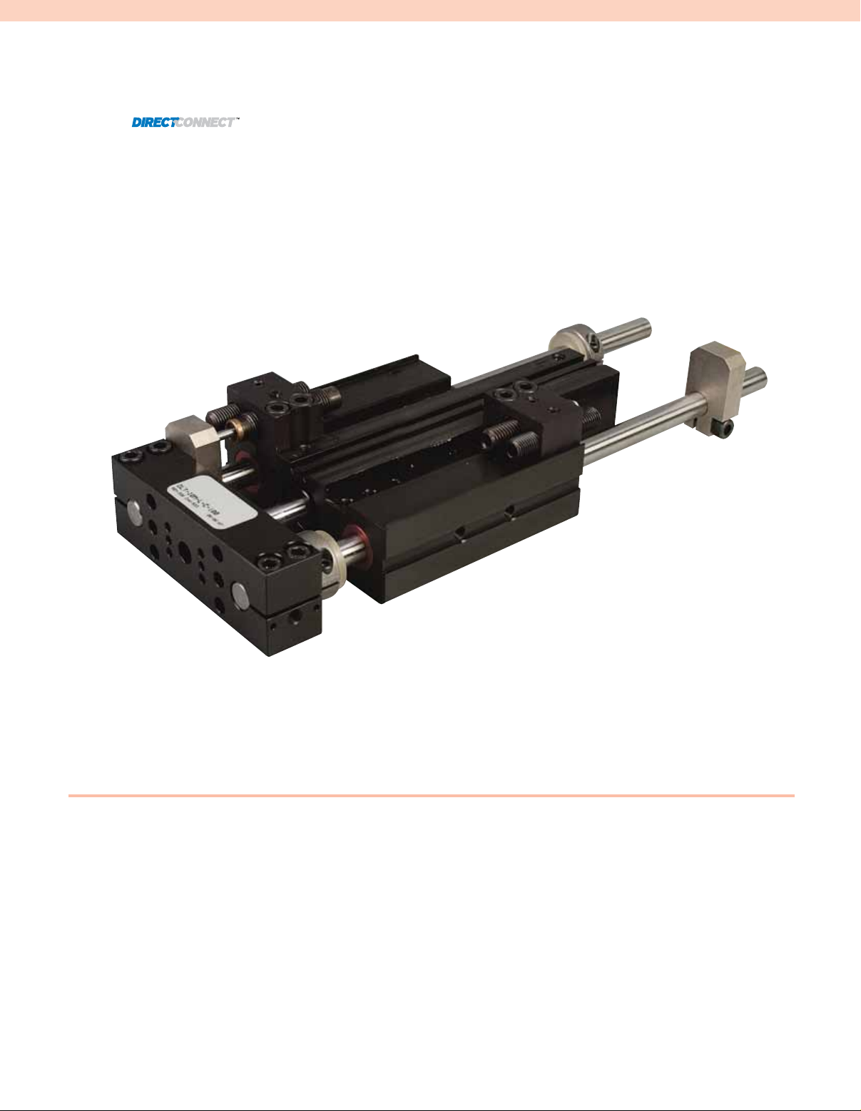
DLT Series
l Highly Configurable
Modular Automation—
Exclusive DirectConnect™
Technology
l Precision Linear Motion—
5 to 150 mm (0.20 to 6")
of Travel
l Thruster Force 89 to 275 N
(20 to 62 lb) at 5.5 bar
(80 psi)
l Repeatability 0.03 mm
(0.001") with Precision
Stop Option
l Up to 5 Million Cycles in
Typical Application—
Up to 10 Million with
Maintenance
l Temperature Operating
Range -35 to 80°C
(-30 to 180°F)
l Double Acting Pneumatic
Cylinder Requiring
3 to 7 bar (40 to 100 psi)
Dry Filtered (40 micron
or Better) Air Supply
Along with a 4-Way,
2 Position Valve
than actual size.
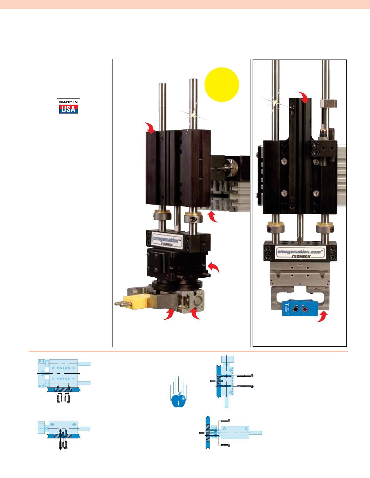
DLT-10M-E-C-50
E-Series short
body linear
thruster slide.
Note: Gripper fingers
are shown for reference
purposes, tooling is the
customers responsibility.
DPP-10M-12 parallel
gripper with OSTW-K-M
thermocouple connector.
Visit omega.com
Two Axis
Motion
Control
DMEX-16-12
mounting
stanchions. Visit
omega.com
DRF-075M-180
rotary actuator.
Visit omega.com
DPP-10M-12 parallel gripper
with SMP-T-F snap-in panel jack
thermocouple connector.
DLT-10M-L-C-100
L-Series long
body thruster.
Visit omega.com
Body mounts with screws
and loacte with slip fit
dowel pin holes on side
using DIRECTCONNECT
mounting patterns.
Body can be mounted from the
back using the DIRECTCONNECT
pattern of threaded mounting and
dowel pin holes.
Body back mounts with screws
from the front using the
clearance and counterbored
DIRECTCONNECT pattern and
located with dowel holes.
G
Payload attaches to tooling
plate DIRECTCONNECT
mounting pattern with screws
and locates using slip fit
dowel pin holes.
C-5
Page 2
Product Features
Sensor Magnet
Standard in piston
Mounting Patterns
Main bodies have tapped and
counterbored through holes
including slip fit dowel holes on
DIRECTCONNECT mounting surface
Inductive Proximity Sensors
4 or 8 mm diameter, threaded body
with quick disconnect
Shock Absorbers
With built-in hard stop;
dual stop capable
Misalignment
Coupling
Increases service life
Universal Mounting Kit
Contains mounting bracket,
hardened steel target,
and hardware; allows the
mounting of shocks and
ajustable hard stops
Urethane Bumpers
& Clamp Collars
Magneto Resistive Sensors
Slot mounted sensor with threaded
quick disconnect
Sensors Grooves
For mounting Magneto
Resistive Sensors
Oil Wick
Supplies constant
bearing lubrication
Aircraft Quality
Aluminum
TECHNICAL SPECIFICATIONS
Pneumatic Specifications
Pressure Operating Range*:
3 to 7 bar (40 to 100 psi)
Cylinder Type: Double acting
Dynamic Seals:
Internally lubricated Buna-N
Valve Required to Operate:
4-way, 2-position
Air Quality Requirements
Air Filtration: 40 micron or better
Air Lubrication: Not necessary
Air Humidity: Low moisture
content (dry)
Preloaded Linear
Ball Bushings
Precision Ground Shafting
Case hardened to RC60-65; corrosion
resistant optional
Temperature Operating Range
Buna-N Seals (Standard):
-35 to 80°C (-30 to 180°F)
FKM Seals (Optional):
-30 to 150°C (-20 to 300°F)
Maintenance Specifications
Expected Life:
Normal Application: 5 million cycles
With Preventative Maintenance:
10+ million cycles**
Field Repairable: No
Seal Repair Kits Available: No
Adjustable Hard Stops
For precision (±0.001") hard stop
end point positioning; allows for stop
adjustment independent of shock
absorber hard stop; dual stop capable
DLT-10M-L-C-100
shown smaller than
actual size.
Application Restrictions:
Flow controls, shock absorbers and
urethane bumpers recommended for
nearly all applications. Use composite
bushing in dirty or gritty environments.
Never use silicone based lubricants with
composite bushings.
* Higher pressure possible. Consult Sales
with application details.
** Addition of lubrication will greatly increase
service life.
C-6
Page 3
L
C
L
C
P
N
M5
AIR PORTS
(A DIA. BORE)
E + STROKE
H
J
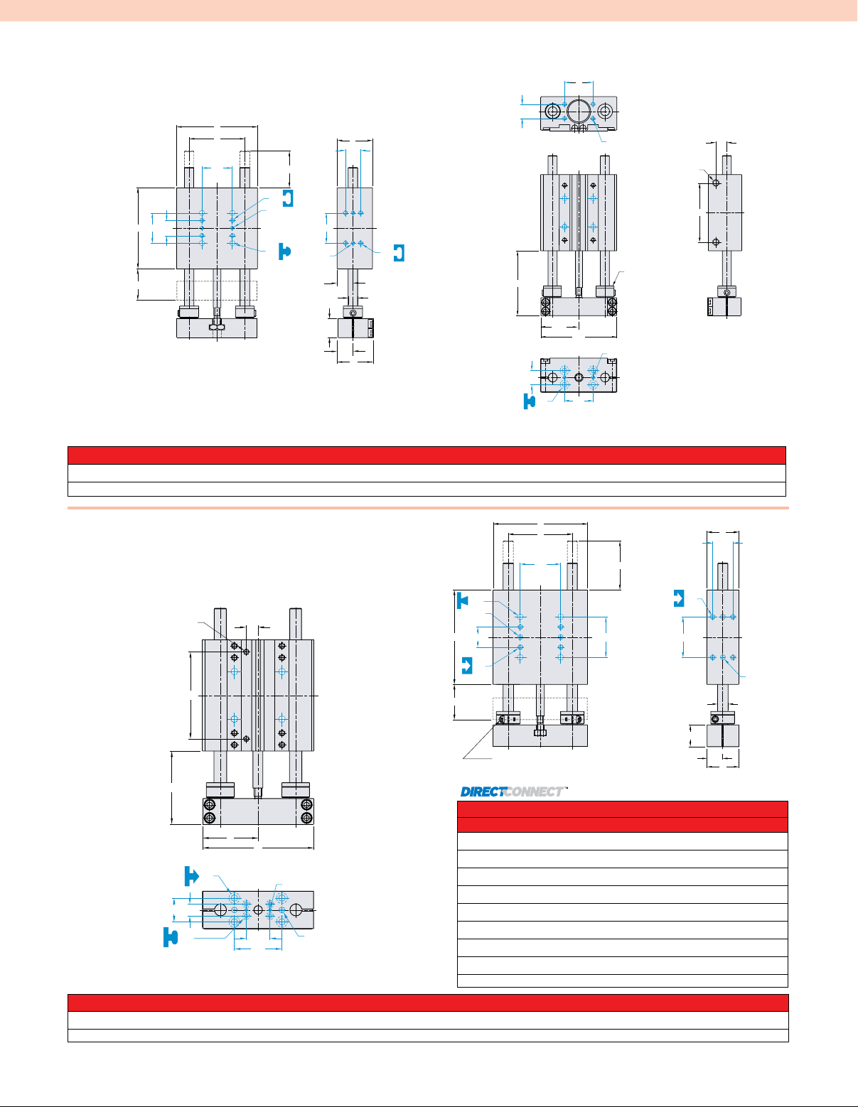
short body thruster
L
C
L
C
L
C
L
C
L
C
L
C
L
C
DQ
DA
DA
DB
DR
E + STROKE
N
P
M5
AIR PORTS
(A DIA. BORE)
STANDARD
H
J
RETRACT
ADJUSTMENT
COLLARS AND BUMPERS
dLt-06m, 08m-e buiLt-in
rePairabLe cyLinder
B
S
DB
C
L
B
DA
DB
E
G + STROKE
DR
DQ
C
L
DT
F
DA
C
L
C
DB
DQ
L
DR
R
C DIA.
DA
E + STROKE
DB
C
L
C
L
C
L
P
C
N
L
C
L
DR
AIR PORTS
(A DIA. BORE)
RETRACT
ADJUSTMENT
COLLARS AND BUMPERS
STANDARD
M5
M
L
K
J
H
C
L
DQ
DA
DB
DS
C
L
Basic Unit Dimensions (mm)
MODEL NO. A B C E F G H J K L M N P R S
DLT-06M-E 14 50.8 6 19.9 22.4 16.8 50.3 25.1 22.2 9.3 11.9 39.4 7.4 9.9 34.93
DLT-08M-E 14 63.5 8 19.9 22.4 10.4 62.7 31 22.2 9.3 11.9 52.1 7.4 9.9 44.95
B
short body thruster
dLt-10m, 12m buiLt-in
rePairabLe cyLinder
M5
AIR PORTS
(A DIA. BORE)
N
E + STROKE
DF
DB
DA
DS
Basic Unit Dimensions (mm)
C
L
P
C
L
J
H
C
L
DQ
C
L
DB
DC
DD
DG
DD
B
DB
DE
E
STANDARD MOUNTING PATTERN FOR ALL SIZES
MILLIMETERS
DA 9.5
DB 19.1
DC 38.1
DD 5 mm H7 x 6 DP
DE M5 x 8.5 DP
DF Clearance for M5
DG Clearance for M5
DQ 3H7 x 2 DP
DS Clr & C’bore for M3
RETRACT ADJUSTMENT
S
DC
C
L
BUMPERS & COLLARS
STANDARD
G + STROKE
C
DC
L
Dimensions
DC
MODEL NO. A B C E F G H J K L M N P R S
DLT-10M-E 19 88.9 9.5 33.4 30.2 20.8 88.6 44.2 29.9 14.8 20.7 69.7 9.4 60.33
DLT-12M-E 25 101.6 12 33.4 41.4 20.8 101.2 50.4 41 20.4 20.7 83.3 9.4 69.85
C-7
F
DB
C
L
DE
C
L
DD
C DIA.
M
L
K
Page 4

Long body thruster
L
C
L
C
L
C
L
C
L
C
DC
DD
DQ
DF
DB
DA
DS
DB
DD
DB
DE
M
C DIA.
F
P
N
Q
E + STROKE
M5
AIR PORTS
(A DIA. BORE)
H
J
K
L
L
C
L
C
L
C
DD
DQ
DF
DB
DA
DS
DB
P
N
Q
E + STROKE
M5
AIR PORTS
(A DIA. BORE)
H
J
dLt-06m, 08m-L buiLt-in rePairabLe cyLinder
F
DA
C
L
C
DB
DQ
M
L
DR
R
L
K
E + STROKE
C DIA.
DA
DS
D
DB
B
E
Basic Unit Dimensions (mm)
B
S
DB
C
L
G + STROKE
DR
DQ
C
DA
L
DT
MODEL NO. A B C D E F G H J K L M N P Q R S
DLT-06M-L 14 50.8 6 44.4 19.9 22.4 16.8 50.3 25.1 22.2 9.3 11.9 39.4 5.4 9.9 34.93
DLT-08M-L 14 63.5 8 44.4 19.9 22.4 10.4 62.7 31 22.2 9.3 11.9 52.1 5.4 9.9 44.95
Long body thruster
dLt-10m, 12m, 16m-L
buiLt-in rePairabLe cyLinder
C
L
C
L
P
M5
AIR PORTS
(A DIA. BORE)
C
N
RETRACT
ADJUSTMENT
COLLARS AND
BUMPERS
STANDARD
J
H
C
L
DQ
C
L
DB
C
M5
AIR PORTS
(A DIA. BORE)
L
P
L
B
S
DC
C
L
D
DG
DD
B
DB
DE
E
RETRACT ADJUSTMENT
BUMPERS & COLLARS
STANDARD
G + STROKE
C
DC
L
F
DB
C
L
DC
DE
DC
C
L
STANDARD MOUNTING PATTERN FOR ALL SIZES
MILLIMETERS
DD
C DIA.
DA 9.5
DB 19.1
DC 38.1
N
Q
E + STROKE
DB
J
DF
DA
DS
Dimensions
H
C
L
DQ
C
L
DD
DB
DC
DD 5 mm H7 x 6 DP
DE M5 x 8.5 DP
M
Basic Unit Dimensions (mm)
L
K
MODEL NO. A B C D E F G H J K L M N P Q R S
DLT-10M-L 19 88.9 9.5 50.8 33.4 30.2 20.8 88.6 44.2 29.9 14.8 20.7 12.7 9.4 9.6 60.33
DLT-12M-L 25 101.6 12 63.5 33.4 41.4 20.8 101.2 50.4 41 20.4 20.7 146.8 9.4 9.1 69.85
DLT-16M-L 25 120.7 16 69.9 34.9 41.4 19.3 120.3 59.9 41 20.4 20.7 172.2 9.4 9.1 82.55
C-8
DF Clearance for M5
DG Clearance for M5
DQ 3H7 x 2 DP
DS Clr & C’bore for M3
Page 5

W
XAM
Loading Curves
12
10
8
6
4
2
0
53
45
35
27
18
9
0
lbs.N
0 0.256.5
13
1
25
1.5
38
.75
19
1.25
32
1.75 in.
44mm
STROKE
)W+F( DAOLYAP+ECROF
"500. )31.(
"200. )50.(
W
XAM
Loading Curves
10
8
6
4
2
0
45
35
27
18
9
0
lbs.N
0
0
.25
6
.5
13
1
25
.75
19
1.25 in.
32mm
STROKE
)W+F( DAOLYAP+ECROF
"500. )31.(
"200.
)50.(
W
XAM
Loading Curves
12
10
8
6
4
2
0
53
45
35
27
18
9
0
lbs.N
0 0.256.5
13
1
25
.75
19
1.25
32
STROKE
)W+F( DAOLYAP+ECROF
"200. )50.(
0
0
.5
13
1
25
1.5
38
2 in.
50mm
Loading Curves
W
XAM
40
35
30
25
20
15
10
5
0
178
156
133
111
89
67
44
22
0
lbs.N
STROKE
)W+F( DAOLYAP+ECROF
00. "2 0.( )5
"500. )31.(
70
60
50
40
30
20
10
0
311
267
222
178
133
89
44
0
lbs.N
0
0
1
25
)W+F( DAOLYAP+ECROF
.5
13
0. 20 " 0.( )
5
1.25 in.
32mm
W
XAM
Loading Curves
12
10
8
6
4
2
0
53
45
35
27
18
9
0
lbs.N
0 0.256.5
13
1
25
1.5
38
.75
19
1.25
32
1.75 in.
44mm
STROKE
)W+F( DAOLYAP+ECROF
"500. )31.(
"200. )50.(
Loading Curves
W
MAX
70
60
50
40
30
20
10
0
311
267
222
178
133
89
44
0
lbs.N
0
0
1
25
3 in.
76mm
STROKE
)W+F( DAOLYAP+ECROF
2
50
2.5
64
1.5
38
.5
13
0. 20 " 0.( )
5
"500. )31.(
"010. )52.(
W
XAM
Loading Curves
.256.5
13
1
25
1.5
38
.75
19
1.25
32
1.75 in.
44mm
STROKE
"500. )31.(
"200. )50.(
W
XAM
Loading Curves
10
8
6
4
2
0
45
35
27
18
9
0
lbs.N
0 0.25
6
.5
13
1
25
.75
19
1.25 in.
32mm
STROKE
)W+F( DAOLYAP+ECROF
"500. )31.(
"200.
)50.(
W
XAM
Loading Curves
12
10
8
6
4
2
0
53
45
35
27
18
9
0
lbs.N
0 0.256.5
13
1
25
1.5
38
.75
19
1.25
32
1.75 in.
44mm
STROKE
)W+F( DAOLYAP+ECROF
"500. )31.(
"200. )50.(
25
20
15
10
5
0
111
89
67
44
22
0
lbs.N
Loading Curves
0
0
.5
13
1
25
1.5
38
2 in.
50mm
STROKE
)W+F( DAOLYAP+ECROF
W
XAM
00. "2 50.( )
"500. )31.(
"010. )52.(
0
0
.5
13
1
25
1.5
38
2 in.
50mm
Loading Curves
W
XAM
40
35
30
25
20
15
10
5
0
178
156
133
111
89
67
44
22
0
lbs.N
STROKE
)W+F( DAOLYAP+ECROF
00. "2 0.( )5
"500. )31.(
Loading Curves
W
MAX
70
60
50
40
30
20
10
0
311
267
222
178
133
89
44
0
lbs.N
0
0
1
25
3 in.
76mm
STROKE
)W+F( DAOLYAP+ECROF
2 502.5
64
1.5
38
.5
13
0. 20 " 0.( )
5
"500. )31.(
"010. )52.(
M
DLT-06M-E & L
DLT-08M-E & L
lbs.N
10
45
)W+F( DAOLYAP+ECROF
8
35
6
27
4
18
2
9
0
0
0
0
.25
6
DLT-10M-E & L
lbs.N
25
111
0
0
00. "2 50.( )
.5
13
)W+F( DAOLYAP+ECROF
20
89
15
67
10
44
5
22
0
0
F=Externally applied force (lbs. or N)
W=Weight of payload (lbs. or N)
F+W=Total force (lbs. or N)
Loading Curves
"200.
)50.(
.5
13
STROKE
Loading Curves
W
STROKE
.75
19
"500. )31.(
XAM
1
25
DLT-16M-L
311
267
)W+F( DAOLYAP+ECROF
222
178
133
89
44
"500. )31.(
W
XAM
1
25
"010. )52.(
1.5
38
lbs.N
70
60
50
40
30
20
10
0
0
0
0
F
W
1.25 in.
32mm
2 in.
50mm
0. 20 " 0.( )
5
.5
13
lbs.N
12
53
10
45
)W+F( DAOLYAP+ECROF
35
27
18
9
0
8
6
4
2
0
0 0.256.5
Loading Curves
"200. )50.(
.75
13
19
W
XAM
1
1.25
25
32
STROKE
DLT-12M-E & L
.5
13
Loading Curves
00. "2 0.( )5
W
1
25
STROKE
W in this range use Urethane Bumpers
"500. )31.(
XAM
1.5
38
lbs.N
40
178
35
156
)W+F( DAOLYAP+ECROF
30
133
25
111
20
89
1
25
Loading Curves
"500. )31.(
1.5
38
STROKE
Shock Absorbers and Flow Controls are recommended for nearly all applications
(W)in this range use Single Shock in both directions
Shaded shock absorption ranges of horizontal payload (W) @ 80psi, flow controls fully open. For vertical
applications do not exceed 1/2 of the recommended payload due to the additional acceleration effect of gravity.
C-9
67
44
22
W
MAX
2
50
15
10
5
0
0
0
0
2.5
64
"010. )52.(
3 in.
76mm
"500. )31.(
1.5
38
50mm
1.75 in.
44mm
2 in.
Page 6

accessories For dLt thrusters
C
D
C
D
E
A
B
C
D
E
C
D
E
Urethane Bumpers
& Clamp Collars
A
B
E
D
C
l Urethane Bumpers for Shock Absorption and Noise Dampening
l Adjustable Clamp Collars for End of Stroke Position Adjustment
l Kit Contains 2 Collars and 2 Shock Pads for Adjustment of Travel
in One Direction
l Kit Required for Extend (Kit for Retract Comes Standard)
Adjustable
Hard Stops
l For Precision (±0.001") End Point Positioning of Retract Position
l Allows for End Stop Position Adjustment Independent of Shock
Absorber Hard Stop
l Allen Wrench Adjustable
Shock Absorbers
l Full Stroking Piston Rod
l Built-In Hard Stop
l Position Adjustable
Universal Mounting Kit
l Kit Mounts One Shock Absorber or One Adjustable Hard Stop
l Kit Includes One Mounting Bracket, One Hardened Tool Steel Target
and Hardware
l Target Allows for Unlimited Retract Stroke Adjustment (No Extend
Position Adjustment); Fine Adjustment is Achieved Using Adjustable
Hard Stop or Shock Absorber
l Mounting Bracket Keys Into Body for Secure Positioning and
Excellent Rigidity
l Four Possible Mounting Positions
Inductive Proximity Sensors
l 4 or 8 mm (0.16 or 0.32") Diameter
l Threaded Quick Disconnect with Built-In LED Output
l PNP and NPN Available
Quick Disconnect Cable
l Threaded Coupling with Knurled Head for Secure Electrical Connections
l 2 m (6.6') Cable Length
l 5 m (16') Cable Length
Magneto Resistive Sensors
l No Mounting Kit Required (Slot Mounted)
l Threaded Quick Disconnect with Built-In LED Output
l PNP and NPN Available
l Low Profile
Quick Disconnect Cable
l Threaded Coupling with Knurled Head for Secure Electrical Connections
l 2 m (6.6') Cable Length
l 5 m (16') Cable Length
Basic Unit Dimensions (mm)
MODEL NO. A B C D E F G
DLT-06M 6.0 12 6.4 7.9 6.9 — —
DLT-08M 6.0 16 6.4 7.9 6.9 — —
DLT-10M 8.7 22.1 9.5 12.2 8.1 14.7 91.4
DLT-12M 9.5 23.9 9.5 11.4 5.8 14.7 91.4
DLT-16M 11.1 33.3 11.1 11.4 8.6 14.7 91.4
C-10
Page 7

To Order Visit omega.com/dlt_series for Pricing and Details
BORE BODY SIZE SHAFT MAX THRUSTER
DIAMETER (Width) DIAMETER LENGTH HEIGHT STROKE WEIGHT FORCE @
MODEL NO. mm (inch) mm (inch) mm (inch) mm (inch) mm (inch) mm (inch) kg (lbs) 5.5 bar (80 psi)
DLT-06M-E-C-25
DLT-08M-E-C-44
DLT-10M-E-C-50
DLT-12M-E-C-50
DLT-06M-L-C-50
DLT-08M-L-C-75
DLT-10M-L-C-100
DLT-12M-L-C-125
DLT-16M-L-C-150
Ordering Example: DLT-06M-E-C-25, pneumatic presision thruster with maximum stroke of 25 mm (0.984").
Recommended accessories include 2 inductive sensors OISP-014, with an inductive sensor mounting kit, OSMK-076. Additional urethane bumper/
stop collar kit, OSAK-067 or 2 precision adjustable hard stops, DLT-0623, with 2 universal mounting kits,
OSAK-069. DLT requires a 4-way, 2-position valve to operate recommended 2 pneumatic flow controls.
CAD drawings available at omega.com
4 (0.55) 50.8 (2) 6 (0.236) 106.1 (4.177) 22.4 (0.882) 25 (0.984) 0.15 (.34) 89 (20)
14 (0.55) 63.5 (2.5) 8 (0.315) 137.8 (5.425) 22.4 (0.882) 44 (1.732) 0.30 (.65) 89 (20)
19 (0.75) 88.9 (3.5) 9.5 (0.374) 193.1 (7.602) 30.2 (1.189) 50 (1.969) 0.84 (1.18) 155 (35)
25 (0.98) 101.6 (4) 12 (0.473) 205.8 (8.102) 41.4 (1.630) 50 (1.969) 1.35 (2.98) 275 (62)
14 (0.55) 50.8 (2) 6 (0.236) 137.5 (5.413) 22.4 (0.882) 50 (1.969) 0.28 (0.61) 89 (20)
14 (0.55) 63.5 (2.5) 8 (0.315) 168.8 (6.646) 22.4 (0.882) 75 (2.953) 0.44 (1.96) 89 (20)
19 (0.75) 88.9 (3.5) 9.5 (0.374) 243.1 (9.571) 30.2 (1.189) 100 (3.937) 0.88 (1.95) 155 (35)
25 (0.98) 101.6 (4) 12 (0.473) 280.8 (11.055) 41.4 (1.630) 125 (4.921) 1.46 (3.21) 275 (62)
25 (0.98) 120.7 (4.75) 16 (0.630) 324.9 (12.791) 41.4 (1.630) 150 (5.906) 2.03 (4.81) 275 (62)
SHOCK/STOP ACCESSORIES
MODEL NO. QUANTITY DESCRIPTION
OSAK-069 1, 2, 3, or 4 Universal mounting kit (shock or stop) for -06M
OSAK-070 1, 2, 3, or 4 Universal mounting kit (shock or stop) for -08M
OSAK-055 1, 2, 3, or 4 Universal mounting kit (shock, stop or sensor) for -10M
OSAK-057 1, 2, 3, or 4 Universal mounting kit (shock, stop or sensor) for -12M
OSAK-059 1, 2, 3, or 4 Universal mounting kit (shock, stop or sensor) for -16M
SHOK-030 1, 2, 3, or 4 Shock absorber for -06M and -08M (2 max on -06)*
SHOK-028 1, 2, 3, or 4 Shock absorber for -10M*
SHOK-010 1, 2, 3, or 4 Shock absorber for -12M and -16M*
DLT-0623 1, 2, 3, or 4 Adjustable hard stop for -06M and -08M*
DLT-1023 1, 2, 3, or 4 Adjustable hard stop for -10M ,-12M and -16M*
OSAK-067 1 Urethane bumper/stop collar kit for -06M
OSAK-068 1 Urethane bumper/stop collar kit for -08M
OSAK-065 1 Urethane bumper/stop collar kit for -10M
OSAK-066 1 Urethane bumper/stop collar kit for -12M
OSAK-060 1 Urethane bumper/stop collar kit for -16M
SENSOR ACCESSORIES
OSMK-076 1 or 2 Inductive sensor mounting kit for -06M
OSMK-077 1 or 2 Inductive sensor mounting kit for -08M
OISP-011 1 or 2 Inductive PNP with quick disconnect
† for -10M, -12M and -16M*
OISN-011 1 or 2 Inductive NPN with quick disconnect† for -10M, -12M and -16M*
OISP-014 1 or 2 Inductive PNP with quick disconnect† for -06M and -08M*
OISN-014 1 or 2 Inductive NPN with quick disconnect† for -06M and -08M*
OHSP-017 1 or 2 Magneto resistive sensor PNP quick disconnect all models
†
OHSN-017 1 or 2 Magneto resistive sensor NPN quick disconnect all models†
CABL-010 1 or 2 Quick disconnect 2 m (6.6') cable length all models†
CABL-013 1 or 2 Quick disconnect 5 m (16') cable length all models†
PNEUMATION ACCESSORIES
SLKT-108 1 Cylinder repair kit for -06M, -08M
SLKT-100 1 Cylinder repair kit for -10M
SLKT-102 1 Cylinder repair kit for -12M, -16M
* Requires universal mounting kit. † Sensor and cable sold separately.
Ordering Example: For DLT-06M thruster slide order two DLT-0623, adjustable hard stops with two OISP-014, inductive PNP sensors,
and two OSMK-076, mounting kits, [sensors require two CABL-013, quick disconnect cables, 5 m (16')].
C-11
 Loading...