

Page 1
®
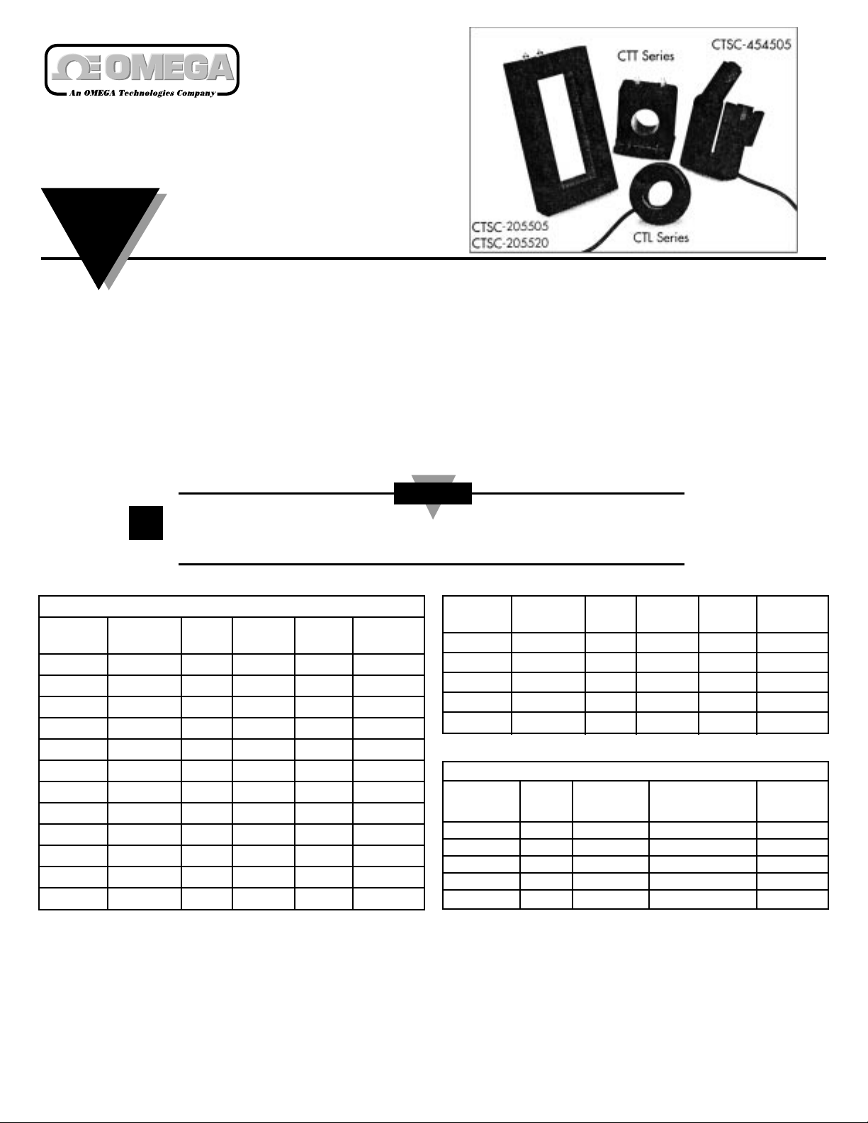
CTL/CTT/CTSC Series
Current Transformers
INSTRUCTION
SHEET
M1858/1097
General Description
For AC currents over 5A, a current transformer (CT) is
normally used to step down the maximum current to
5A and isolate the meter at the same time, thus
avoiding common mode problems.
Current transformers are specified by a turns ratio such
as 100:5, where the first number is the rated input current
in amps and the second number is the 5A output. When
specifying and AC or true-RMS meter for use with a 5A
current transformer, specify the reading desired at 5A
input to the meter. Current transformers are self-isolating
from the circuit being measured.
OMEGA’s CTL/CTT/CTSC Series Current Transformers
can be used with OMEGA’s DP25-CRMS, DP2000-D7,
DP2000-G7 or DP18-RTI digital indicators, all of which
can be scaled to display current.
Accuracy is specified as a percentage of the range, and
is given for the maximum burden as expressed in volt
amperes. The total burden includes the input resistance
of the meter and the loop resistance of the wire and
connections between the current transformer and meter.
Example: Burden = 2.0 Volt Amps. Maximum Voltage
drop = 2.0 Volt Amps / 5 Amps = 0.400 Volts. Maximum
Resistance = Voltage / Current = 04.00 Volts / 5 Amps =
0.080 Ohms.
If the input resistance of the meter is 0.010 Ohms, then
0.070 Ohms is allowed for loop resistance of the wire,
and connections between the current transformer and
the meter. The length and gauge of the wire must be
considered in order to avoid exceeding the maximum
burden. If resistance in the 5 amp loop causes the
burden to be exceeded, the current will drop. This will
result in the meter reading low at higher current levels.
Current transformers may develop voltages which are hazardous to personnel
or equipment if the secondary circuit is open when primary current is present.
▲
!
CAUTION
Available Models
One Piece Current Transformers
CTL Series CTT Series Current Window Burden VA
Model No. Model No. Ratio Diameter Accuracy @ 60 Hz
CTL-050005 CTT-050005 50:5 0.50" ±1.5% 2.5
CTL-050010 CTT-050010 100:5 0.50" 1.0% 3.0
CTL-094020 CTT-094020 200:5 0.94" 1.0% 12.5
CTL-113005 CTT-113005 50:5 1.13" 3.0% 2.0
CTL-113010 CTT-113010 100:5 1.13" 1.0% 2.0
CTL-113020 CTT-113020 200:5 1.13" 1.0% 4.0
CTL-113030 CTT-113030 300:5 1.13" 1.0% 8.0
CTL-156005 CTT-156005 50:5 1.56" 2.0% 1.0
CTL-156010 CTT-156010 100:5 1.56" 2.0% 2.0
CTL-156020 CTT-156020 200:5 1.56" 1.0% 5.0
CTL-156050 CTT-156050 500:5 1.56" 1.0% 20.0
CTL-156100 CTT-156100 1000:5 1.56" 1.0% 25.0
Split Core Current Transformers
ANSI Metering
CTSC Series Current W indow Class Accuracy Burden VA
Model No. Ratio Dimensions BO.1 BO.2 BO.5 @ 60 Hz
CTSC-205505 500:5 2.00" x 5.50" 2.4 4.8 - 2.0 ±1%
CTSC-205520 2000:5 2.00" x 5.50" 0.6 0.6 0.6 30.0 ±1%
CTSC-454505 500:5 4.50" x 4.50" 4.8 4.8 - 1.5 ±1%
CTSC-454520 2000:5 4.50" x 4.50" 0.6 0.6 1.2 20.0 ±1%
CTSC-081902 200:5 0.80" x 1.95" - - - 2.5 ±4%
CTL Series CTT Series Current Window Burden VA
Model No. Model No. Ratio Diameter Accuracy @ 60 Hz
CTL-206005 CTT-156005 50:5 2.06" 3.0% 0.5
CTL-206010 CTT-206010 100:5 2.06" 1.0% 1.0
CTL-206020 CTT-206020 200:5 2.06" 1.0% 4.0
CTL-206050 CTT-206050 500:5 2.06" 1.0% 12.5
CTL-206100 CTT-206100 1000:5 2.06" 1.0% 10.0
Page 2

WARRANTY
OMEGA warrants this unit to be free of defects in materials and workmanship and to give
satisfactory service for a period of 13 months from date of purchase. OMEGA Warranty
adds an additional one (1) month grace period to the normal one (1) year product
warranty to cover handling and shipping time. This ensures that OMEGA’s customers
receive maximum coverage on each product. If the unit should malfunction, it must be
returned to the factory for evaluation. OMEGA’s Customer Service Department will issue
an Authorized Return (AR) number immediately upon phone or written request. Upon
examination by OMEGA, if the unit is found to be defective it will be repaired or replaced
at no charge. However, this WARRANTY is VOID if the unit shows evidence of having been
tampered with or shows evidence of being damaged as a result of excessive corrosion; or
current, heat, moisture or vibration; improper specification; misapplication; misuse or
other operating conditions outside of OMEGA’s control. Components which wear or which
are damaged by misuse are not warranted. This includes contact points, fuses, and triacs.
OMEGA is glad to offer suggestions on the use of its various products. Nevertheless,
OMEGA only warrants that the parts manufactured by it will be as specified and
free of defects.
OMEGA MAKES NO OTHER WARRANTIES OR REPRESENTATIONS OF ANY KIND
WHATSOEVER, EXPRESSED OR IMPLIED, EXCEPT THAT OF TITLE AND ALL
IMPLIED WARRANTIES INCLUDING ANY WAR-RANTY OF MERCHANTABILITY AND
FITNESS FOR A PARTICULAR PURPOSE ARE HEREBY DISCLAIMED.
LIMITATION OF LIABILITY: The remedies of purchaser set forth herein are
exclusive and the total liability of OMEGA with respect to this order, whether based
on contract warranty, negligence, indemnification, strict liability or otherwise, shall
not exceed the purchase price of the component upon which liability is based. In no
event shall OMEGA be liable for consequential, incidental or special damages.
Every precaution for accuracy has been taken in the preparation of this manual; however,
OMEGA ENGINEERING, INC. neither assumes responsibility for any omissions or errors
that may appear nor assumes liability for any damages that result from the use of the
products in accordance with the information contained in the manual.
SPECIAL CONDITION: Should this equipment be used in or with any nuclear installation or
activity, purchaser will indemnify OMEGA and hold OMEGA harmless from any liability or
damage whatsoever arising out of the use of the equipment in such a manner.
OMEGA’s policy is to make running changes, not model changes, whenever an
improvement is possible. This affords our customers the latest in technology and
engineering.
OMEGA is a registered trademark of OMEGA ENGINEERING, INC.
Benelux:
Postbus 8034, 1180 LAAmstelveen,
The Netherlands
Tel: (31) 20 6418405 FAX: (31) 20 6434643
Toll Free in Benelux: 06 0993344
e-mail: nl@omega.com
Czech Republic:
ul. Rude armady 1868, 733 01 Karvina-Hranice,
Czech Republic
Tel: 420 (69) 6311899 FAX: 420 (69) 6311114
e-mail: czech@omega.com
France:
9, rue Denis Papin, 78190 Trappes
Tel: (33) 130-621-400 FAX: (33) 130-699-120
Toll Free in France: 0800-4-06342
e-mail: france@omega.com
Servicing Europe:
USA and Canada:
Sales Service: 1-800-826-6342 / 1-800-TC-OMEGA
SM
Customer Service: 1-800-622-2378 / 1-800-622-BEST
SM
Engineering Service: 1-800-872-9436 /
1-800-USA-WHEN
SM
TELEX: 996404
EASYLINK: 62968934 CABLE: OMEGA
USA: ISO 9001 Cer
tified
One Omega Drive, Box 4047
Stamford, CT 06907-0047
Tel: (203) 359-1660
FAX: (203) 359-7700
e-mail: info@omega.com
Servicing North America:
For immediate technical or application assistance:
Mexico and Latin America:
Tel: (95) 800-TC-OMEGA
SM
FAX: (95) 203-359-7807
En Espan~ol: (203) 359-7803
e-mail: espanol@omega.com
Germany/Austria:
Daimlerstrasse 26, D-75392
Deckenpfronn, Germany
Tel: 49 (07056) 3017 FAX: 49 (07056) 8540
Toll Free in Germany: 0130 11 21 66
e-mail: germany@omega.com
United Kingdom: ISO 9002 Cer
tified
•25 Swannington Road, Broughton Astley,
Leicestershire, LE9 6TU, England
Tel: 44 (1455) 285520 FAX: 44 (1455) 283912
•P.O. Box 7, Omega Drive, Irlam,
Manchester, M44 5EX, England
Tel: 44 (161) 777-6611 FAX: 44 (161) 777-6622
Toll Free in England: 0800-488-488
e-mail: uk@omega.com
Canada:
976 Bergar
Laval (Quebec) H7L 5A1
Tel: (514) 856-6928
FAX: (514) 856-6886
e-mail: canada@omega.com
®
OMEGAnetSMOn-Line Service Internet e-mail
http://www.omega.com info@omega.com
CTL/CTT/CTSC Series Current Transformers
Primary/Secondary Turns Ratio
Modification
The nameplate current ratio of the current transformer
is based on the condition that the primary conductor
will be passed once through the transformer opening. If
necessary, this rating can be reduced in even multiples
by looping this conductor two or more times through
the opening. Atransformer having a rating of 300
amperes will be changed to 75 amperes if four loops or
turns are made with the primary cable as illustrated.
The ratio of the current transformer can be also
modified by altering the number of secondary turns by
forward or back-winding the secondary lead through
the window of the current transformer.
By adding secondary turns, the same primary
amperage will result in a decrease in secondary output.
By subtracting secondary turns, the same primary
amperage will result in greater secondary output.
Again using the 300:5 example, adding two secondary
turns will require 310 amps on the primary to maintain
the 5 amp secondary output or 62/1p = 310p/5s.
Subtracting two secondary turns will only require 290
amps on the primary to maintain the 5 amp secondary
output or 58s/5p = 290p/5s. The ratio modifications are
achieved in the following manner:
To add secondary turns, the white lead should be wound
through the CT from the side opposite the polarity mark.
To subtract turns, the white lead should be wound
through the CT from the same side as the polarity mark.
*Formula: Ns
= Ip where: Ns = Number of Secondary Turns
Np Is Np = Number of Primary Turns
Ip = Primary Amperage
Is = Secondary Amperage
Example of Primary/Secondary Turn Ratio Modification
with a 300:5 Current Transformer
UUSASA
MADE
ININ
 Loading...