

Page 1
omega.com
e-mail: info@omega.com
For latest product manuals:
omegamanual.info
User’s Guide
CS7500 / CS7600
M-4382/1006
Shop online at
Page 2

Servicing North America:
USA: One Omega Drive, P.O. Box 4047
ISO 9001 Certified Stamford CT 06907-0047
TEL: (203) 359-1660 FAX: (203) 359-7700
e-mail: info@omega.com
Canada: 976 Bergar
Laval (Quebec) H7L 5A1, Canada
TEL: (514) 856-6928 FAX: (514) 856-6886
e-mail: info@omega.ca
For immediate technical or application assistance:
USA and Canada: Sales Service: 1-800-826-6342 / 1-800-TC-OMEGA
®
Customer Service: 1-800-622-2378 / 1-800-622-BEST
®
Engineering Service: 1-800-872-9436 / 1-800-USA-WHEN
®
TELEX: 996404 EASYLINK: 62968934 CABLE: OMEGA
Mexico: En Espan˜ol: (001) 203-359-7803 e-mail: espanol@omega.com
FAX: (001) 203-359-7807 info@omega.com.mx
Servicing Europe:
Benelux: Postbus 8034, 1180 LA Amstelveen, The Netherlands
TEL: +31 (0)20 3472121 FAX: +31 (0)20 6434643
Toll Free in Benelux: 0800 0993344
e-mail: sales@omegaeng.nl
Czech Republic: Frystatska 184, 733 01 Karviná, Czech Republic
TEL: +420 (0)59 6311899 FAX: +420 (0)59 6311114
Toll Free: 0800-1-66342 e-mail: info@omegashop.cz
France: 11, rue Jacques Cartier, 78280 Guyancourt, France
TEL: +33 (0)1 61 37 2900 FAX: +33 (0)1 30 57 5427
Toll Free in France: 0800 466 342
e-mail: sales@omega.fr
Germany/Austria: Daimlerstrasse 26, D-75392 Deckenpfronn, Germany
TEL: +49 (0)7056 9398-0 FAX: +49 (0)7056 9398-29
Toll Free in Germany: 0800 639 7678
e-mail: info@omega.de
United Kingdom: One Omega Drive, River Bend Technology Centre
ISO 9002 Certified Northbank, Irlam, Manchester
M44 5BD United Kingdom
TEL: +44 (0)161 777 6611 FAX: +44 (0)161 777 6622
Toll Free in United Kingdom: 0800-488-488
e-mail: sales@omega.co.uk
OMEGAnet®Online Service Internet e-mail
www.omega.com info@omega.com
It is the policy of OMEGA to comply with all worldwide safety and EMC/EMI regulations that
apply. OMEGA is constantly pursuing certification of its products to the European New Approach
Directives. OMEGA will add the CE mark to every appropriate device upon certification.
The information contained in this document is believed to be correct, but OMEGA Engineering, Inc. accepts
no liability for any errors it contains, and reserves the right to alter specifications without notice.
WARNING: These products are not designed for use in, and should not be used for, human applications.
Page 3

TABLE OF CONTENTS
SPECIFICATIONS 2
UNPACKING AND STARTUP 3
OPERATIONAL FEATURES 5
MENU ACCESS 7
OPTION CONFIGURATION 9
MENU NAVIGATION 14
7600 MENU ENTRY 14
7500 MENU ENTRY 15
CAL 40, FILTER & CALIBRATION 16
CFG 50 COUNTING FUNCTIONS 17
CFG 60 RS232 CONFIGURATION 17
CAL 70 TIME AND DATE 18
CAL 80 FORMATED PRINT SLOT 18
CONTINUOUS OUTPUT PRINT CODES 19
COMMAND FORMATS 21
RS232 PIN ASSIGNMENTS 23
AVERAGE PIECE WEIGHT STORAGE 24
WEIGHING WITH/WITHOUT TARE 25
COUNTING 26
DISPLAY MESSAGES 32
STATUS CHARACTERS 33
115 TO 220 VAC CONVERSION 34
1
Page 4

SPECIFICATIONS
LOAD CELL A/D CONVERTER
TYPE: 24 bit delta sigma
EXCITATION: 5 VDC, 120 mA max .
SIGNAL INPUT: 16 mv
SENSITIVITY: 0.1 uV/grad
UPDATE RATE: 30 update/second
DISPLAY: Six (6) Decades, 0.6 inch LED
INDICATORS: Gross, Tare, Net, Zero, Stable, Base, Units, Count .
POWER INPUT: 117/217 VAC, 50-60 HZ, 20 watts, fuse 0.25 A Slo-Blow.
SERIAL PORT: RS232C
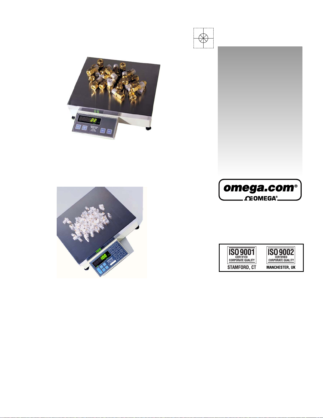
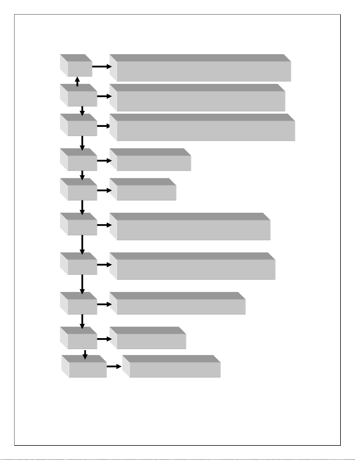
COUNTING SCALE: Cast Aluminum, 14” (L) x 15.5” (W) x 5.25 (H); 15.25 lbs.
OPTIONS:
TIME & DATE: 12/24 hr, battery backed.
AC/DC: Battery backed (counting Scale).
REMOTE DISPLAY: Wall or post mount.
DUAL CHANNEL: Independent A/D converter.
2
Page 5

Unpacking and Startup
Counting Scales:
After opening the shipping carton, remove the molded foam top from the carton. (On
2 lb. and 5 lb. capacity scales the platform is packaged on top of this foam, remove it
first and lay it aside.)
Gently lift and remove the stainless steel platform cover only.
Remove any options which may be packed with the scale.
Carefully remove scale from the packaging by grasping both sides of the base.
DO NOT LIFT SCALE BY THE TOP SPIDER OR SUB-PLATFORM ASSEMBLY.
Place the scale on a stable, level surface for operation.
Adjust the corner leveling feet until the level bubble indicates the unit is level. Firmly
tighten hex jam nuts on the leveling feet. (Any time the scale is relocated, it should be
leveled.)
Remove the protective plastic wrap from the platform and place the platform on the
spider.
To activate the scale, plug the line cord into any grounded 50/60 hertz 120 volt outlet.
3
Page 6

Operational Features
Automatic Zero-Tracking (AZT) - Maintains the system zero and is normally set to +/-
1/4 of the display resolution.
Count/Weigh - Scale is capable of both counting and weighing functions. The count
may be turned off on the 7600 if not needed.
Four Selectable Sample Sizes - Four different sample sizes may be entered into the
scale memory during programming.
Counting Functions - A variety of different counting methods may be employed,
depending on type of counting selected during calibration.
Sample Update - Piece weight accuracy may be improved after the initial sample by
adding a quantity of parts between 10% and 100% of the original sample to the
platform. When this is done the scale will recalculate the piece weight, display the new
percent error/accuracy for 2 seconds and then return to the counting mode.
Second Base - An optional second base is available to expand the capacity of the
scale.
Peak/Hold – Captures the peak reading directly (based on filter settings) or after preset
number of “stable” readings.
Accumulation – Based on count or weight.
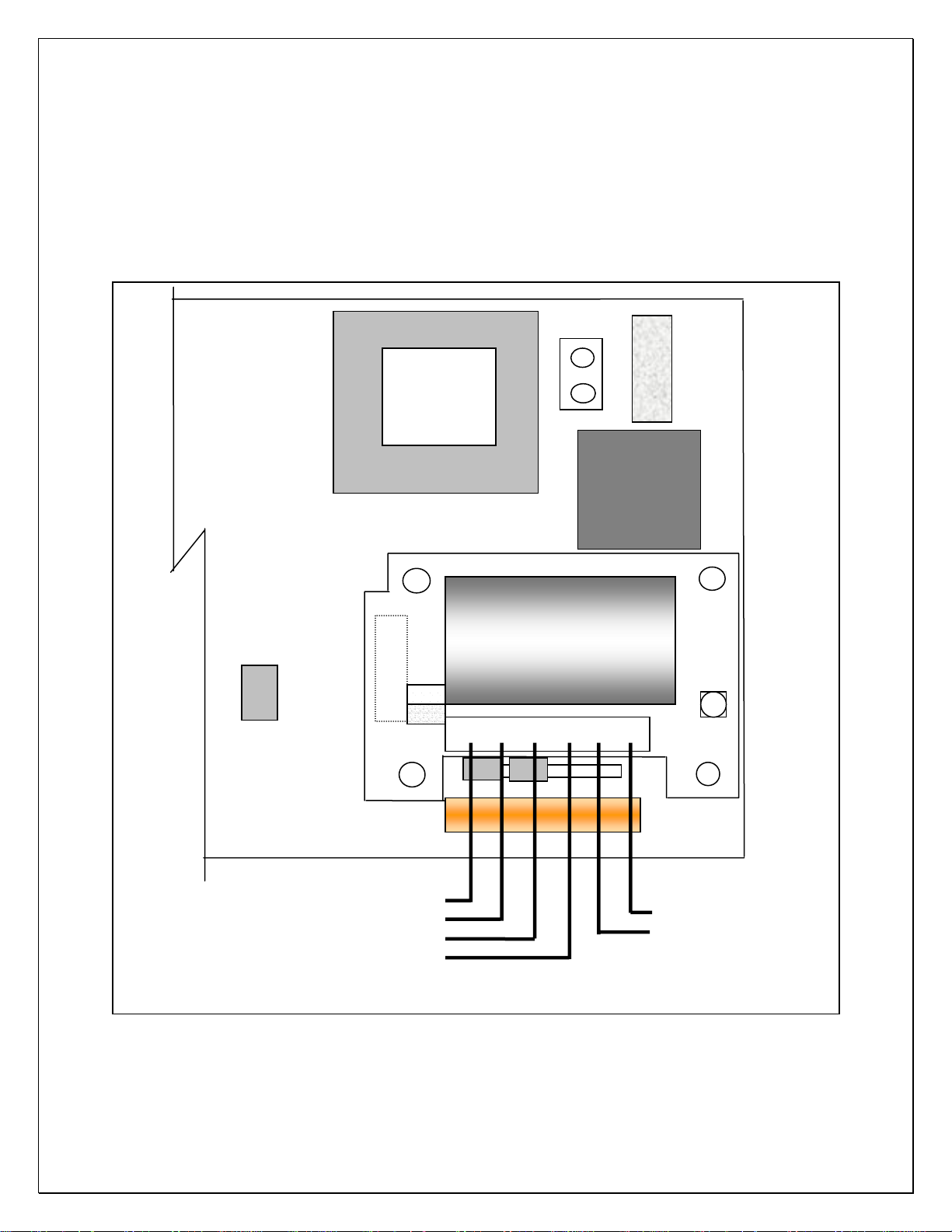
Counting Scale Connectors:
The following connectors may be accessed through the opening on the bottom of the
scale.
D-Subminiature Connector (9-pin) - Used with RS-232 Interface.
Remote Display Connector - Used to connect a remote display option to the scale.
REMOTE BASE CPC Style connector (8 pin) - Same as indicator wiring.
5
Page 7

Operational Features
Push-Button Functions
ZERO Button - Sets the scale to zero.
UNITS Button - Used to switch the scale between the primary weighing unit,
secondary weighing unit, and the count mode.
PRINT Button - Transmits formatted print to any device connected to the RS-232
port. Holding this push-button for four seconds will access the RS-232 configuration
mode.
SAMPLE SET Button - Places the scale in the sample set mode for counting
operations. Hold to access setpoint targets when enabled.
7600 18-Key: Full Numeric + Enhanced Operation
GROSS/NET Button - Switches the scale display between Gross weight and Net
weight.
PIECE WEIGHT Button - Will cause the scale to display the presently stored piece
weight, if any, and puts it into the piece weight entry mode.
TARE Button - Will tare off any weight setting on the platform and enter it into the tare
memory.
KEYPAD TARE Button - Will display whatever tare is presently stored in the tare
memory and puts the scale into the keypad tare entry mode.
BASE Button - Used to switch the scale between base 1 and base 2, when the
second base option is installed.
% Button - Used to display the percent of error, or percent of accuracy. (Only if these
features have been selected during programming.)
ID Button - Will display whatever ID number is presently stored in the ID memory
and puts the scale into the ID entry mode.
CHECK Button - Pressing this button will cause the scale to initiate the diagnostic
countdown. It may also be used as a continue key if the scale should freeze on any of
the diagnostic numbers during countdown.
CLEAR Button - Used when the scale is in one of the data entry modes. Pressing this
button once will put a decimal point onto the display and pressing it a second time will
clear the display.
ENT Button - Used when the scale is in one of the data entry modes. Button is used
to enter information into the system memory.
6
Page 8

Menu Access:
To access instrument configuration, calibration or to enable options, depress the “Zero”
key for five seconds.
The Audit Trail counters (“Pxxxx” and “Cxxxx”) are displayed first followed by access
code request (“AC?”). The initial factory setting is “0000” which is entered “AC0000” and
“Print”. If no entry is made, instrument returns to operate mode. Stepping the “Zero” key
when “AC?” is on, will display software version, display check and keypad test.
Configuration and Calibration
Key Functions
The 7500 4-Key access functions (------)
ZERO
(DP/Clear)
DP/Clear: Enters a decimal point or double push clears the display.
Increment: Scrolls selection of sub parameters or increments value for numeric entry.
Advance: Multiplies a numeric entry by “10”.
Enter: Stores entry and steps to the next parameter or exit.
The 7600 (18-Key) uses direct key entry.
The access code can be changed to any four digit combination when exiting setup and
display is “AC ?”, either input change and enter or use enter alone to exit.
SAMPLE
(Increment)
UNITS
(Advance)
PRINT
(Enter)
Front panel access is inhibited if conventional “sealing” is applied by
setting jumper J1-1 in the B position. The internal “CAL” button is
then used for access.
subsequent stepping of the button will select 7300, 7400, 7500, 7600, etc. Leave on
current model and allow time out to incorporate.
Holding the “CAL”, will display the current “7X00” and
7
Page 9
Menu Layout:
CAL1
Options: Dual / Triple Range, Peak Hold, Remote Inputs,
Setpoints, UPS Worldship, Accumulate, Analog Output
CAL 10
Capacity, Auto Configuration, Initial Zero, Enable Count,
Enhance Mode
CAL 20
Capacity, Resolution, Zero Range, Units, Print, Overrange,
Zero Tracking
CAL 30
Secondary Resolution
CAL 40
Filter, Zero, Span
CFG50
Counting Functions, Sample Size, Switch Mode,
Percent Error, Auto Sample/Bulk, Negative Sample
CFG60
RS232 Configuration: Baud Rate, Word, Stop, Parity,
Echo, Address
CAL 70
Time & Date: 12/24 hr, AC/DC Sleep Set
CAL 80
Formatted Print Slot
CAL 200 Remote Display AC/DC only
8
Page 10
Option Configuration (Cal 1):
Step Parameter Definition
bat 1 OFF, On
dtr 2 0……15
dtr High Res. Medium Res.
0 ---- --- ---- ---1 50% X2 ---- ---2 50% X5 ---- ---3 25% X2 ---- ---4 25% X5 ---- ---5 20% X2 ---- ---6 20% X5 ---- ---7 20% X10 ---- ---8 10% X2 ---- ----
9 10% X5 ---- ---10 10% X10 ---- ---11 25% X5 50% X2
12 10% X5 50% X2
13 25% X10 50% X2
14 10% X10 50% X2
15 1% X100 10% X10
Charger enabled/disabled
(AC/DC board only)
Dual/Triple Range (0 = off)
Step Parameter Definition
Peak/Hold function, zero key clears current
PHd 3 OFF, Peak-H, Hold
peak, tare function is disabled, print code 22
and 32 are modified to value and value with
labels (xx.xxx / Peak xx.xxx lb)
HdS 3.1 0……240
Hold after “samples”: Weight must be stable
for 0 – 240 samples to “hold”.
Remote inputs,(with DIO option) Input 1:
Rln 4 no, yes
Gross/net, Input 2: Tare, Input 3: Zero,
Input 4: Print
UPS WorldShip, Parameters 25, 60-69, 80 +
UPS 5 no, yes
are hidden, format:9600/odd/7/2,“39” outputs
the UPS format.
9
Page 11
ACC 6 OFF, A-Cnt, Cnt, A-Prl, Prl
AOS 7 Gross, Net, Display
Zr 7.1 0.00
FS 7.2 Full-scale
Zr.A 7.3 Zero Cal Adjust
SP.A 7.4 Span Cal Adjust
INSTRUMENT CAL UP CAL DOWN
A-Cnt: Auto count accumulator
Cnt: Manual count accumulator
A-Pri: Auto primary units accumulator
Pri: Manual primary units accumulator
Sets the weight that the output represents:
Gross, Net, or Display.
Sets the value of weight that is equal to
4mA/0V.
Sets the value of weight that is equal to
20mA/10V.
Use the cal up/down keys (table II) to set the
output to as close to 4mA/0V that is
acceptable to one’s requirements.
Use the cal up/down keys (table II) to set the
output to as close to 20mA/10V that is
acceptable to one’s requirements.
7500 SAMPLE UNITS
7600 UNITS/4 PRINT/7
SPt 8
OFF, Tr, Prtr, drtr, drtk,
C tr, C Prtr, C drtr, C drtk
Out 8.1 CHG, dIO
dIO Relays as per SPt 8
CHG
tr : Target weight relay K1
Prtr : tr + Preact weight
Drtr : tr + Dribble weight relay K2
Drtk : tr + dr + Trickle weight relay K3
C tr : Target count relay K1
C Prtr : tr + Preact count
C drtr : tr + Dribble count relay K2
C drtk : tr + dr + Trickle count relay K3
CHG : Uses battery ckt to drive LED
dIO : Uses relay board, K1-3.
tr : LED on < tr, off > tr
Prtr : on < Pr, flashes <tr, off > tr
Drtr : on < dr, flashes <tr, off > tr
Drtk : on < dr, flashes fast < tk, slow < tr
10
Page 12
r
Option Configuration Dual Channel:
P20
Sense Jumpers
Plus….. 1-2
Minus… 3-4
1 2
A
J1
B
EW-1000 Rev…..
Excitation +
Excitation –
P5
P20
Sense +
Sense -
Transformer
1 2
3 4
6 5 4 3 2 1 TB-20
EW -1000-CH2
A/D Converter
F1
Line
Filte
0.25A
SB
CAL/SEL
Signal +
Signal -
11
Page 13

Option Configuration DIO:
AC Inputs; D1, D2 are not installed, J1 = short (underside), J2 = open, R1 – R4 = 18k
(3w, 5%, flame proof).
DC Inputs; D1, D2 are installed, J1 = open (cut trace), J2 = short, R1 – R4 = 1.5k (1/2w,
5%, carbon film).
Gross/Net IN 1
COM
COM
Tare IN 2
Zero IN 3
Print IN 4
K1
K2
K3
TB 30
1
2
3
4
5
6
D1
D2
1
2
3
4
5
6
7
8
TB 31
J1
J2
EW-1000-DIO
P4
EW-1000 Rev…
12
Page 14

r
Option Configuration Analog Output:
Transformer
P5
A
J1
B
1 2
J1
V
I
8 7 6 5 P11
EW-1000 Rev…..
6 5 4 3 2 1 TB-1
F1
Line
Filte
EW-1000-AOUT
TB 20
1 2
- +
- +
0 – 10 Vdc or 4 – 20 ma
Position J1 & J2 for V/I
0.25A
SB
J2
V
I
13
Page 15

Menu Navigation
Configuration Blocks: 50, 60, 70 and 80 may be accessed form the front panel of the
scale by pressing and holding the PRINT button for 2 seconds. The scale will then
display CFG 60. At this point, you can press ENT to select this category or key in the
number of any of the other accessible categories.
Configuration/Calibration Main Blocks: 10, 20, 30, etc can be stepped to directly
by incrementing “CAL 10” to “20” and “enter” (Options are CAL 1). The sub
parameters need to step through to the next “main” before a direct change.
From any “main” point, exit by changing to “CAL 0” and “enter”. A “store” “no”
will need to be changed to “yes” to save any changes. Changing to “CAL 0” from
within “CAL 40” allows exit prior to adjusting span.
NOTE: During the setup procedure each step will be printed to any device interfaced to
the RS-232 port. If options are not present, steps will not appear.
7600 Menu entry point:
Step Parameter Definition
bAS ? 1, 2
CAL 10
CAP 11
Full Capacity Key in the capacity of the base.
ACL 12 Yes, No
A-0 13 Yes, No
Cnt 14 Yes, No
EnH 15 Yes, No
Str 16 OFF, A
Select 1(main) or 2(remote base) and ENT.
Only when dual channel installed.
Capacity, auto-config, Initial zero, count
(Press ENT or inc/ENT to step).
Auto configuration. Use the UNITS button to
select YES or NO. If YES the scale will jump
to Cnt 14, EnH, Prt 25 and CAL 40 storing
defaults "*". If NO is selected the scale will
proceed to the next step.
Select if scale is to auto zero when first
turned on. Use the UNITS button to select
YES or NO*.
Turn count mode on or off. Use the UNITS
button to select YES* or NO.
Turn on for count “enhance” mode. (skipped
if count is off)
Enables average piece weight storage.
14
Page 16

Step Parameter Definition
CAL 20
CAP 21 Full capacity
rES 22 1, 2, 5
-0- 23 1.9, 10, 30
UnS 24 1, 2, 3, 4, …..14
Prt 25 Stable, First, Unstbl, ntEP
Cnd 26 Yes, No
0-t 27 0.00
Capacity, resolution, zero, units, print, zero
track .
By-passed when entered in CAL 10.
Resolution - Input Scale Resolution. Default
(*) entry is the capacity of the scale divided
by 5000 and rounded to the nearest 1, 2, 5.
Zero Range - Input the Zero Range in % of
full scale. The amount of weight the scale is
allowed to Zero.
Select the primary weighing unit by keying in
a number :1 = lb*, 2 = kg, 3 = g, 4 = oz t, 5 =
lb t, 6 = g, 7 = dwt, 8 = oz, 9 = c, 10 = oz f,
12 = l, 11 = ml, 13 = tons, 14 = lb - oz
Print: Select whether the scale will respond
to a print request when stable, first (positive)
stable, any time (unstable), or NTEP.
Overrange: Select YES (9d) or NO (105%)*.
Zero tracking value entered as a percent of
display resolution. Entering a 0.25* equals
25% of one display graduation. “0” disables
the zero tracking feature.
SbL 28 OFF, 1, 3, 5, 10
CAL 30
2Un 31 1, 2, 3, 4, …..14..15(user)
2rE 32 1, 2, 5, (plus user)
CnU 33 0.000001 to 999999
EPn 34 n = -4 to 4, (10^n)
PUd 39
PrI, SEC, SEC On, COUnt,
SELECt
Select motion in grads/sec.
Secondary units, resolution.
Select secondary weighing unit by keying in a
number: 1 = lb*, 2 = kg, 3 = g, 4 = oz t, 5 = lbt,
6 = g, 7 = dwt, 8 = oz, 9 = c, 10 = oz f, 12 = l,
11 = ml, 13 = tons, 14 = lb – oz, 15 = user
Secondary weighing resolution. Key in the
resolution for the secondary weighing unit.
Conversion Factor ( 31 must be set on 15)
Multiplier exponent (0.0001 to 10000)
Power up: Primary units, Secondary units,
Secondary units and Count, Count, With RTC
Gross/Net restored.
15
Page 17

Step Parameter Definition
CAL 40
FIL 41 0, 1, 2, 3, ….9, 11…15
nol 42 0.00
HLF43 XXX.XX
FUL44 XXX.XX
nol 45
Filter, zero/span calibration.
Response time: 0-9 selects conversions to
average directly. 11-15 correspond to 25,
30, 35, 40, & 50 conversions for extended
filtering.
No Load - With the platform in place but no
weight on the scale, press ENT. Display will
indicate “------“ and step if reading is
acceptable.
Entering a “0” during this sub-menu will
jump to the beginning “CAL 40” to allow
bypassing span changes. A second “0”
will exit setup and question “SAVE” to
effect changes or abort.
Half Capacity - Apply a half capacity weight
to the platform and press ENT.1/2-capacity
weight is unavailable, place a substitute
weight on the platform and key in the amount
of weight being used and press ENT. Display
will indicate “------“ and step if reading is
acceptable.
Full Capacity - Apply a full capacity weight to
the platform and press ENT. If a full-capacity
weight is unavailable, place a substitute
weight on the platform, key in the amount of
weight being used and press ENT.
No Load - Remove all weight from the
platform and enter.
16
Page 18

Step Parameter Definition
CFG 50 (7500, 7600 only) Counting functions. (Cnt 14-yes)
SS1 51 10
SS2 52 20
SS3 53 50
SS4 54 100
PCt 55 Yes, No (7600 only)
Enh 55 Yes, No (7500 only)
2S 56 Yes, No (7600 only)
Pr 57
ASb 58 Yes, No (7600 only)
nEG 59 Yes, No
CFG 60
bAU 61
P Err, P Acc, disable
(7600 only)
300,600,1200,2400,
4800, 9600*, 19200, 38400
Key in first sample size. (Normal entry is 10).
Set to “0” to turn off count mode.
Key in sample size two. (normal entry is 20)
Key in sample size three (normal entry is 50)
Key in sample size four (normal entry is 100)
Select if piece weight is to be displayed as
weight per 1000.
Turn on for count “enhance” mode. (skipped
if count is off)
Enable Two Switch counting method.
Percent of error, percent accuracy, disable
the percent error feature.
Select automatic sample-to-bulk. (dual
channel required)
Select if negative sampling will be allowed
during two switch, top end counting.
RS-232 Configuration (This step can also be
reached from the front panel by pressing and
holding the PRINT button for 2 sec.)
BAUD RATE: Select a baud rate using the
UNITS button.
LEn 62 7, 8
SPb 63 1, 2
PAr 64 None, Odd, Even
Ech 65 No Ech, Ech
Cdr 66 0…255
WORD LENGTH: Select: 7 bits*, 8 bits.
STOP BITS: Select: 1 stop bit*, 2 stop bits.
PARITY: Select: None, Even, Odd*.
Select: No Echo*, Echo.
ADDRESS: Key in a number from 0* to 255,
0 disables this feature.
17
Page 19

Step Parameter Definition
CAL 70 7600 std, 7500 option
StF 71 0, 1, 2, 3
td1 72 HH MM SS
td2 73 MM DD YY
SLP 74 0…12
Setting of time and date.
Select type of clock: 0 = Time and date OK,
skip to SLP 74, 1 = 24 hour clock, 2 = 12
hour clock, currently AM, 3 = 12 hour clock,
currently PM.
Enter the current time as HHMMSS. Based
on the type of clock selected in step 71.
Clock will begin with the pressing of the ENT
button.
Enter the current date as MMDDYY.
For AC/DC versions of the scale, enter the
amount of time the display is to remain on
before going into the battery saver sleep
mode. The time is entered in number of
minutes, from .5 to 12. Entering a zero will
disable the sleep mode for AC only scales.
CAL 80 Formatted print slot programing
BUILDING A FORMATTED PRINT
The user defined formatted print is the string of information sent from the RS-232 port
when the PRINT button is pressed, or the scale receives an SRP command from a
computer or terminal. The user selects the format of this string by entering two digit print
codes into the 20 available print slots, PSL 81 through PSL 101. When you are finished
entering data to construct the formatted print, "99" is entered to mark the end of print
formatting.
EXAMPLE OF BUILDING A FORMATTED PRINT
To build a simple formatted print that could be sent to a ticket printer the following print
codes could be entered:
PSL 81 - 30 (gross w/ prefix & suffix.) The result:
PSL 82 - 65 (CR/LF)
PSL 83 - 32 (net w/ prefix & suffix.)
PSL 84 - 65 (CR/LF)
PSL 85 - 31 (tare w/ prefix & suffix.)
PSL 86 - 65 (CR/LF)
PSL 87 - 99 (End)
GROSS 1.205 lb
NET 0.205 lb
TARE 1.000 lb
18
Page 20

FORMATTED PRINT CODES
02 Time 12 "Base" prefix 22
03 Date 13 "ID" prefix 23 Count 33 Count pre.data & suffix
net weight
(or Peak)
Net weight prefix, data,
32
suffix, (or Peak)
04 unit suffix label 14 FR”F1” 24 Piece Weight 34
"GROSS"
05
prefix
06 "TARE" prefix 16 P1 26
07 "NET" prefix 17 27 Base in use 37
"COUNT"
08
prefix
"PIECE
09
WEIGHT"
prefix
"SAMPLE
10
SIZE" prefix
"err" or "acc"
11
prefix (%=error
/ accuracy)
Note: In lb-oz mode, 20-22 will print oz only, 30-32 will print lb-oz.
15 25 Sample Size 35
% Error or
Accuracy
18 28 ID Number 38 ID Number prefix, data
19 "Pcs" suffix 29 39 UPS format
Gross weight
20 gross weight 30
21 tare weight 31
prefix, data
and suffix
Tare pre.data
& suffix
Continuous Output Print Codes
Continuous output (Formatted print will be sent continuously as long as scale is
50
turned on.)
Toggled continuous output (The formatted print will be sent continuously after the
51
PRINT button is pressed or an SRP command is received by the scale. Pressing
the PRINT or sending SRP a second time will turn off the continuous output.)
Status Character (May be used by a computer to determine the condition of the
52
scale at any given moment.
ABO Checksum (May be used in building a continuous output compatible with other
53
Pennsylvania Scales.)
Piece Weight prefix, data,
suffix
Sample Size prefix data &
suffix
Percent Error/Accuracy
36
prefix, data, and suffix
Base in Use prefix & data
40-
Print strings 1 – 9
49
54 Select Leading Zeros
19
Page 21

Print Special ASCII Characters Formatted Print Codes
60 ASCII space (SP)
61 ASCII horizontal tab (HT)
62 ASCII line-feed (LF)
63 ASCII start of header (SOH)
64 ASCII carriage return (CR)
65 ASCII carriage return and line feed (CR LF)
66 ASCII form-feed (FF)
67 Turn on large print (PA Scale printer)(SO, HEX 0EH)
68 Turn off large print (PA Scale printer)(SI, HEX 0FH)
69 ASCII null (NUL)
78 Invert print (PA Scale printer)(DC3, HEX 13H)
79 End inverted print (PA Scale printer)(DC4, HEX 14H)
80 Print accumulator name, value and units
81 Print “Accum. Total”
82 Print accumulator value
83 Print Force a clear accumulator and transaction counter
84 Print Prompt clear accumulator and transaction counter
85 Print transaction name and counter
86 Print “Transaction”
87 Print transaction counter
98 “98” is a second print string triggered by the Accumulator.
99 Marks the end of the formatted print
CAL 0 Press ENT to exit calibration.
20
Page 22

COMMAND FORMATS
The Model 7600 can be controlled from an external device (such as a computer or
terminal) by various commands, each three letters long, which represent related English
phrases or words. For example, to tell the scale to zero, type ZRO followed by a carriage return.
The basic command formats are:
[<add>]<cmd><cr>
<cmd> [<xx.xx>]<cr>
Where <cmd> is a three-letter command, <add> is a scale address number (0-255),
<cr> represents a carriage return, and <xx.xx> is a mixed number, the brackets [ ] are
used to indicate an optional part of the command.
Examples:
SRP<cr> Send a formatted print
ITW 13.43<cr> Instructs scale to set tare weight
to 13.43 in the current unit
5 SGW<cr> Instructs the scale with address #5 to
send the Gross weight.
General Commands
ATW Acquire Tare Weight
CHK Initiate self-diagnostics CHecK
LCK LoCK out keypad
RES RESet, clears tare weight and count information
SCM Select Count Mode
SSS Select Sample Size
SWM Select Weight Mode
UCK UnloCK keypad
UNP UNit Primary
UNS UNit Secondary
ZRO ZeRO scale
21
Page 23

Commands Which Enter Information into the Unit
IBA [ FLOATING POINT NUMBER ] Input BAse number (with option)
IPW [ FLOATING POINT NUMBER ] Input Piece Weight
ITW [ FLOATING POINT NUMBER ] Input Tare Weight
IID [Up to 15 characters, 0 - 9 & hyphen] Input ID
IUS [Print string, 40 – 49] Input Print string
Commands Which Request Information
SBA Send BAse in use (with second base option)
SCO Send COunt
SDT Send DaTe
SGW Send Gross Weight
SID Send Part ID
SMI Send Metrological Information
SNW Send Net Weight
SPC Send Print Codes
SPR Send PeRcent error or accuracy
SPW Send Piece Weight
SRP Send Requested Print
SSZ Send Sample siZe
STM Send TiMe
STW Send Tare Weight
SVN Send Software Version Number
NOTES: All commands and parameters must be separated by spaces. The entire
command string must be terminated with a carriage return.
22
Page 24

Custom serial string command: IUS
IUS x y, where x selects the string 1 – 10 and y is the string comprised of up to 22
characters. The strings are printed with using the format codes 40 – 49
where string 1 is 40, 2 is 41, etc.
IUS <enter>: List all strings
IUS 1<enter>: Clears string one
RS-232 PIN ASSIGNMENTS AND IMPLEMENTED FUNCTIONS
Connection to the Serial Port is made via a DB-9 female connector found in the access
area on the bottom of the scale. Instrument connection is on TB-2.
PIN EIA CODE FUNCTION DIRECTION
2 BB Transmit Data Output
3 BA Receive Data Input
5 AB Signal Ground -
GND
Tx1, RS232
Rx1, RS232
TB-2
1
2
3
DB-9
EW-1000 Rev…
23
Page 25

Average Piece Weight Storage
APW ID memory in 7600 counting scale mode (This function is not available for
other instrument selections).
Parameter 16, “STr 16” selects OFF or A.
The “A” selection is expanded storage of APW’s. Key in an ID or, using the TARE
(NEXT) or KEYPAD TARE (LAST) keys, selects a currently stored ID. If the ID exists
and has APW>0, the stored APW is loaded into the PIECE WEIGHT memory and
the count display is selected. If the ID is new or has an APW= 0 (initial value when
the ID is first entered), the “Add xx” prompt is displayed so an APW can be
established and stored to ID memory.
Key functions during ID selection/entry:
KEY FUNCTION
ZERO Clear ID
Print all IDs w/ their stored APWs and
GROSS/NET
integrity status (OK or ERR). See the text
box to the right.
TARE Select next ID
TARE
Select last ID
RECALL
Press and release to clear the currently
CLEAR
selected ID, or press and hold to access
the “clear all” prompt.
ENTER
Enter if keyed in or select the displayed
ID.
COUNTING SCALE ID MEMORY
0 1200 0.00500 OK
1 2000 0.00338 OK
2 8080 0.00484 OK
3 6800 0.00415 OK
4 6811 0.00472 OK
5 8085 0.00326 OK
6 6812 0.00470 OK
7 100000 0.00163 OK
8 80188 0.02129 OK
9 6808 0.0003 OK
10 1000 0.00334 OK
11 8051 0.00831 OK
12 80186 0.00166 OK
13 6502 0.00117 OK
14 74244 0.00014 OK
15 74573 0.00799 OK
16 100 0.00824 OK
Key in a new or existing ID and then
press the enter key to accept.
0-9
Note: While one is keying in an ID, one can press the blue zero key to abort the
entry and view the last keyed or selected ID.
Specifications:
Storage locations: 250
ID size: six-digit (0-9)
Data stored: ID, APW, and CRC verification number.
24
Page 26

WEIGHING WITHOUT TARE
1. If the second base option has been installed, press the BASE button to select
base 1 or base 2. When base 2 is selected the base 2 LED will be lit. When base
one is selected the base 2 LED will be out. If base 2 has been locked out during
calibration, the word "Error" will momentarily show on the display.
2. Press the UNITS button to select either the Primary weighing unit or the
secondary weighing unit. (Associated indicator will be lit.)
3. Verify that the "GROSS" indicator is lit. If not, press the GROSS/NET button to
light this indicator and put the scale into the gross weight mode.
4. Establish a base zero by pressing ZERO with nothing on the scale platform to
clear any existing weight readings.
5. Place the item(s) to be weighed on the platform and read the weight on the
display.
NOTE: If very light items (less then 1/4 of the display resolution) are placed
on the platform individually, the weight may be zeroed off by the AZT
feature. Add light items to the platform simultaneously.
WEIGHING WITH TARE
1. If the second base option has been installed, press the BASE button to select
base 1 or base 2. When base 2 is selected the "base 2" LED will be lit. When
base one is selected the base 2 LED will be out. If base two has been locked out
during calibration, the word "Error" will momentarily show on the display.
2. Press the UNITS button to select either the Primary or the Secondary weighing
unit. (Associated indicator will be lit.)
3. Press the ZERO button with nothing on the platform to establish a base zero.
4. A tare weight may be acquired using one of the following methods:
a. Place the container or object to be tared off on the platform and press
TARE; or
b. Press the KEYPAD TARE button and then key in the weight of the
container or object, and press ENT.
5. The net weight value will be displayed on the weight display and the NET
indicator will be lit.
6. Pressing the GROSS/NET button will toggle between gross weight and net
weight.
7. When a tare value is stored in the system, the TARE indicator will be illuminated.
8. Place the objects to be weighed in the container and read the net weight on the
display. To clear a tare value, remove all weight from the scale and press TARE,
or press KEYPAD TARE, key in 0 and press ENT.
NOTE: IF the tare has been acquired using the TARE button, the tare value may
be viewed by pressing KEYPAD TARE. Pres ENT to return to the weight display
without altering the tare weight.
25
Page 27

COUNTING
An electronic counting scale counts parts by knowing the weight of a single piece,
dividing that into the total weight on the scale and displaying the result. With the 7600,
this piece weight may
be entered into the scale by one of two methods:
FIRST: Counting out a "sample" quantity of the parts and placing them onto the
scale. The scale will take the weight of the sample, divide it by the known
quantity and derive a piece weight used to count the rest (or "bulk") of the
parts.
SECOND: If the individual piece weight of the parts is already known, this weight
value may be entered into the scale via the keypad.
SAMPLE SIZE:
If the "sample" method of piece weight entry is used, the total weight of the sample must
be at least 0.04% of platform capacity or the scale will not recognize the sample. When
sampling, it is always advantageous to use the largest sample possible. Not only does
the larger quantity tend to average variations in the weight of individual pieces, but the
heavier sample weight improves the counting accuracy of the scale itself.
NORMAL COUNTING PROCEDURE
ONE SWITCH COUNTING - The 7600 is normally shipped from the factory set
up to follow this counting procedure. Unless your 7600 has been programmed for one of
the
alternate counting choices, this procedure is the only one necessary to learn.
NORMAL COUNTING - Using Sample
1. If a container will be used to hold items being counted, place it on the platform.
2. Press the SAMPLE SET button. The scale zeroes. "AddXXX" appears on the display
(where "XXX" is one of the four pre-programmed sample sizes.). Repeated pressing
of the switch successively displays the four sample sizes entered during calibration.
3. If a different sample size is required, key in the desired sample size (do not press
ENT).
4. Place the entire sample on the platform at one time. (If the scale has been
programmed to show the percent of error; this value will be displayed momentarily at
this time.) The scale will now automatically switch to the count mode, displaying the
number of parts in the sample.
5. All of the remaining parts may now be added to the scale and counted. ZERO,
TARE and KEYPAD TARE buttons may now be used without affecting the piece
weight.
6. To count a different part, return to step one.
26
Page 28

NORMAL COUNTING - Keypad Piece Weight Entry
If the individual weight of the parts being counted is known in advance the piece weight
may be entered through the keypad. This eliminates the need for the sample set
operation. (If the percent of error feature has been selected in programming, the scale
will not calculate the percent of error when keypad entry of piece weight is used.)
1. Select the appropriate weighing unit (primary or secondary) for the piece weight
being entered by pressing the UNITS/4 switch.
2. Press the PIECE WEIGHT switch. The display will alternately show "PC" and any
previously stored piece weight.
3. Key in the weight of one piece and press ENT.
4. The scale will go into the count mode.
5. If a container will be used to hold the parts, place it onto the scale and use the
ZERO and/or TARE buttons to zero the scale. Add the parts to the scale at this time.
NOTE: The parts in a full container may also be counted by placing the full container
onto the scale and using KEYPAD TARE to key in the tare weight of the container.
ALTERNATE COUNTING METHODS
The 7600 may be programmed to perform a wide variety of different counting methods.
the following section describes these counting methods, refer to the "Calibration and
Programming Manual" for information on setting your scale to perform one of these.
Two Switch Counting
The 7600 can be programmed so that when the scale is in the sample set mode, the
sample will not be accepted until the ENT button is pressed. This allows parts to be
added to the platform one at a time, where as with the one switch method all of the
sample must be added at once.
Top-End Counting
The total number of items in an unsealed container can be determined without removing
the items from the container (except a sample). The container with parts is placed on
the platform and the piece weight is calculated when a sample quantity is either added
to (one switch) or removed from (two-switch operation) the container. Based on the
piece weight, the total number of items in the container is displayed.
Automatic Sample-to-Bulk Counting
This method requires that the scale be configured with two bases, a "sample" and a
"bulk" base. The lighter capacity "sample" base is used to calculate the piece weight,
and the parts are counted on a heavier capacity "bulk" base. In most cases, higher
counting accuracy is achieved with this method because the calculated piece is more
precise when the sample is weighed on the light-capacity sample base. In normal
operation, when the sample is placed on the sample base, the scale automatically
switches to the bulk base and items to be counted are placed on the bulk base.
27
Page 29

Counting by First Determining Error of Count (One-Switch Method using
Automatic Sample Update)
The percent error/accuracy of count can be updated by adding more items to the
sample after the initial sample size is placed on the platform and the percent
error/accuracy has been displayed. In normal operation , the sample is placed on the
platform and a percent error/accuracy is momentarily displayed, followed by the count.
More pieces are then placed on the platform in the range of 10% to 100% of the original
sample. A new piece weight is calculated based on the larger sample size, and the new
percent of error/accuracy will be momentarily displayed. This may continue until a
satisfactory percent of error/accuracy is achieved.
Counting by First Determining Error of Count (Two-Switch Method)
The percent error of count can be determined before the piece weight is established.
Sample pieces are added to the platform until the percent of error/accuracy is
acceptable. The sample size (number of pieces) is then keyed-in and entered, and the
scale is ready to be used for counting.
Piece Weight Displayed as Weight Per 1000 Pieces
If selected in calibration, the piece weight can be displayed as weight per 1000 pieces.
This option is useful when the items being counted are very light and the piece weight
for one item would be an extremely small number. When entering the piece weight
through the keypad (for normal counting), enter the weight for 1000 items if the piece
weight is to be displayed as weight per 1000 pieces.
Negative Counting
This method is used to count the number of items removed from a container without first
knowing the piece weight. The number of items removed from the container is shown on
the display as a negative number.
Normal Operation with Two Switch Counting
1. If a container will be used to hold items being counted, place it on the platform.
2. Press the SAMPLE SET button. The scale zeroes. "AddXXX" appears on the display
(Where "XXX" is one of the four pre-programmed sample sizes.). Repeated pressing
of the switch successively displays the four sample sizes entered during calibration.
3. If desired, a different sample size may be keyed into the scale. As this number is
entered, the word "Add" will disappear and only the count indicator will be lit to
indicate that the scale is in the sample entry mode.
4. The sample may now be placed onto the scale, all at once or one at a time. (If the
percent of error feature has been selected in programming, the percent of error will
be displayed as the parts are placed onto the platform. The more parts that are
added, the lower the percent of error will be.)
5. Press the ENT button. The scale will switch to the count mode and display the
sample count.
6. The remaining parts to be counted may now be placed onto the scale.
28
Page 30

Normal Operation with Automatic Sample to Bulk Feature
The second base option needs to be installed and calibrated for automatic
sample to bulk to operate. Base one is always the sample base and base two is
always the bulk base.
1. Press the BASE/1 switch to select the bulk base. (Base two indicator should
be lit)
2. Press the ZERO switch to zero the bulk base.
3. If an empty container will be used to hold items on the bulk base place it on
the platform and press either the ZERO or TARE switch.
4. If a full container will be counted on the bulk base. Place the container on the
platform, press the KEYPAD TARE switch and key in the weight of the
container, press ENT.
5. If a container will be used to hold the sample on base 1, place the container
on the scale at this time.
6. Press the SAMPLE SET button. The scale will switch to the sample base
(base 1). "AddXXX" will appear on the display (where "XXX" is one of the four
pre-programmed sample sizes). Select the desired sample size by repeatedly
pressing the SAMPLE SET switch, or key in an alternative sample size.
7. If the scale is programmed for a one-switch operation place the entire sample
on the sample base all at one time. The scale will momentarily display the
percent error/accuracy (If selected in calibration.), switch to the bulk base and
enter the counting mode. The bulk base is now ready to count the parts.
8. If the scale is programmed for a two switch operation, place the sample parts
onto the platform all at once or one at a time. The display will show the
percent of error/accuracy (If selected in calibration.). When all of the sample
parts are on the scale press ENT. The scale will switch to the bulk base and
enter the count mode. The bulk base is now ready to count the parts.
9. At this point ZERO and TARE switches may be used without affecting the
piece weight.
Top-End Counting (One-Switch Method; Sample Added)
1. Press ZERO to zero the scale.
2. Place container with parts on the platform.
3. Press KEYPAD TARE, key in the tare weight of the container, then press
ENT.
4. Remove the sample from the container.
5. Press the SAMPLE SET switch. "AddXXX" will appear on the display (where
"XXX" is one of the four pre-programmed sample sizes). Select the desired
sample size by repeatedly pressing the SAMPLE SET switch, or key in an
alternative sample size. IMPORTANT:The displayed sample size must
equal the number of sample items removed.
6. Place the sample pieces that were removed back into the container. The
scale will momentarily display the percent error/accuracy (If selected in
calibration.) and enter the count mode.
7. The display will show the total count for the items in the container.
29
Page 31

Top-End Counting (Two-Switch method; Sample Removed)
1. Press ZERO to zero the scale.
2. Press KEYPAD TARE, key in the tare weight of the container, then press
ENT.
3. Place the container with contents on the platform and press the SAMPLE
SET switch. "AddXXX" will appear on the display (where "XXX" is one of the
four pre-programmed sample sizes). Select the desired sample size by
repeatedly pressing the SAMPLE SET switch, or key in an alternative sample
size.
4. Remove the displayed sample quantity from the container. The display will show the
percent error/accuracy (If selected in calibration.). Press ENT.
5. The scale will enter the count mode and display the number of parts in the container.
6. Return the sample pieces to the container.
Counting by First Determining Error of Count using Automatic Sample
Update (Normal Operation; One-Switch Method)
1. If a container will be used to hold items being counted, place it on the
platform.
2. Press the SAMPLE SET switch. "AddXXX" appears on the display (where
"XXX" is one of the pre-programmed sample sizes). Select the desired
sample size by repeatedly pressing the SAMPLE SET switch, or key in an
alternative sample size.
3. Place the sample pieces on the platform simultaneously. The Percent
error/accuracy will be momentarily displayed and the scale will enter the
counting mode.
4. To either decrease the percent of error or increase the percent of accuracy,
place more items on the platform in the range of 10% to 100% of the original
sample quantity. A new piece weight is calculated based on the larger sample
size, the new percent of error/accuracy is momentarily displayed and the
scale returns to the count mode. This may continue until the desire percent
error/accuracy is achieved.
5. Removing the original sample or adding a quantity of parts greater than the
original sample will disable the automatic update feature.
30
Page 32

Counting by First Determining Error of Count (Two-Switch Method)
1. If a container will be used to hold the items being counted, place it on the
platform.
2. Press the SAMPLE SET switch for two seconds. "AddXXX" will appear on the
display (where "XXX" is one of the pre-programmed sample sizes). Select the
desired sample size by repeatedly pressing the SAMPLE SET button or key
in a new sample size.
3. Place the sample onto the platform all at one time (this should be done if the
parts are extremely small) or count them onto the platform one at a time.
4. The display will show the percent error/accuracy. Continue to count parts onto
the platform, as the sample increases the percent error will decrease and
accuracy will increase. When the percent error/accuracy is acceptable key in
the quantity of parts on the platform and press ENT.
Counting by First Determining Error of Count with Automatic Sample-ToBulk Feature (Two-Switch-Method)
1. Press the BASE/1 switch to select the bulk base. (BASE 2 light should be lit)
2. Press the ZERO to zero the bulk base.
3. If a container will be used to hold items on the bulk base, place the container
on the platform and press ZERO or TARE.
4. If a container will be used to hold the sample parts, place it onto the sample
base at this time.
5. Press the SAMPLE SET switch for two seconds. "AddXXX" will appear on the
display (where "XXX" is one of the pre-programmed sample sizes). Select the
desired sample size by repeatedly pressing the SAMPLE SET switch or key
in a new sample size.
6. Place the sample onto the platform all at once (this should be done if the
parts are extremely small) or count them onto the platform one at a time.
7. The display will show the percent error/accuracy. If the percent error/accuracy
is not acceptable, continue to count parts onto the platform, as the sample
increases the percent error will decrease and the percent accuracy will
increase. When the percent error/accuracy is acceptable, key in the quantity
of parts on the platform and press ENT.
8. The scale will switch to the bulk base. Items may now be counted on the bulk
base.
Negative Counting, Sample Removed (Two Switch Method)
1. With nothing on the scale platform, press the TARE to set tare to zero.
2. Place the container with contents on the platform.
3. Press the SAMPLE SET switch. “AddXXX” will appear on the display (where
“XXX” is one of the four pre-programmed sample sizes). Select the desired
sample size by repeatedly pressing the SAMPLE SET switch, or key in an
alternative sample size.
4. Remove the displayed sample quantity from the container. The display will
show the percent error/accuracy (If selected in calibration). Press ENT.
5. The scale will enter the count mode and display the number of parts removed
from the container as a negative number. Removing pieces increases the
negative count.
31
Page 33

MESSAGE DESCRIPTION
DAC D/A card detected - Displayed under the check function.
IIC.ERR IIC short - Power-up hardware failure indication.
RST EEPROM is reset by EER command - Power-up message
ON
AUTO EEPROM is reset - Power-up message
ERR6.x Key-pad key is stuck.
-232- Serial calibration/setup is active.
UPDATE Enhancement calculation in progress.
LO.BATT Low battery
D BATT Dead battery
ULULUL Under-load (-400 graduations under dead-zero)
OLOLOL
------ A/D acquisition is in progress.
7x00 Instrument mode selection.
Err 10 Number > 999999
Err 13 Number < -99999
ADC.Err A/D hardware failure (channel one only).
CHECK Check mode accessed.
rC.xxxx Lower four-digits of the ROM check-sum.
Err.80 Serial command data error.
Err.81 Unknown serial command.
-CAL- Remote calibration
Err.OFF Hardware failure of the D.C. power on/off circuitry.
RTC.RST The clock is reset to 01:01:04 12:00:00am.
RST ID
AC OK Access code entered has been accepted.
E-1234 EEPROM set 1,2,3, and/or 4 have been fixed.
Err 40
Err 31 Bad tare entry
Err 30 Push to Zero out of range
PC Err Piece Weight Entry is out of range
Displayed on power-up when the DC power push-button is
pressed.
Over-load (+9 graduations or 105% from dead-zero
reference)
The ID EEPROM has been reset since it was detected as
corrupt.
Positive or negative signal overload (check sense
connections).
32
Page 34

STATUS CHARACTERS:
@ Gr, pri, sta, non-zero U Net, sec, sta, zero
A Gr, pri, sta, zero V
B Gr, pri, unsta, non-zero W Net, sec, unsta, zero
C Gr, pri, unsta, zero X OL/UL, Net, pri, sta
D Gr, sec, sta, non-zero Z OL/UL, Net, pri, unsta
E Gr, sec, sta, zero \ OL/UL, Net, sec, sta
F Gr, sec, unsta, non-zero ^ OL/UL, Net, sec, unsta
G Gr, sec, unsta, zero ‘ Cnt, pri, sta, non-zero
H OL/UL, Gr, pri, sta a Cnt, pri, sta, zero
J OL/UL, Gr, pri, unsta b Cnt, pri, unsta, non-zero
L OL/UL, Gr, sec, sta c Cnt, pri, unsta, zero
N OL/UL, Gr, sec, unsta d Cnt, sec, sta, non-zero
Net, sec, unsta, nonzero
P Net, pri, sta, non-zero e Cnt, sec, sta, zero
Q Net, pri, sta, zero f
R Net, pri, unsta, non-zero g
S Net, pri, unsta, zero h OL/UL, Cnt, pri, sta
T Net, sec, sta, non-zero j
l OL/UL, Cnt, sec, sta n OL/UL, Cnt, sec, unsta
p
r
t
v
x OL/UL, Net, Cnt, pri, sta z
Net, Cnt, pri, sta, nonzero
Net, Cnt, pri, unsta, nonzero
Net, Cnt, sec, sta, nonzero
Net, Cnt, sec, unsta,
non-zero
Cnt, sec, unsta, nonzero
Cnt, sec, unsta, zero
OL/UL, Cnt, pri, unsta
q Net, Cnt, pri, sta, zero
s Net, Cnt, pri, unsta, zero
u Net, Cnt, sec, sta, zero
Net, Cnt, sec, unsta,
w
zero
OL/UL, Net, Cnt, pri,
unsta
33
Page 35

115 to 220 VAC Conversion : EW1000 Bottom Side
CUT CLAD
2-Places
ADD Jumper
34
Page 36

WARRANTY/DISCLAIMER
OMEGA ENGINEERING, INC. warrants this unit to be free of defects in materials and workmanship for a
period of 13 months from date of purchase. OMEGA’s WARRANTY adds an additional one (1) month
grace period to the normal one (1) year product warranty to cover handling and shipping time. This
ensures that OMEGA’s customers receive maximum coverage on each product.
If the unit malfunctions, it must be returned to the factory for evaluation. OMEGA’s Customer Service
Department will issue an Authorized Return (AR) number immediately upon phone or written request.
Upon examination by OMEGA, if the unit is found to be defective, it will be repaired or replaced at no
charge. OMEGA’s WARRANTY does not apply to defects resulting from any action of the purchaser,
including but not limited to mishandling, improper interfacing, operation outside of design limits,
improper repair, or unauthorized modification. This WARRANTY is VOID if the unit shows evidence of
having been tampered with or shows evidence of having been damaged as a result of excessive corrosion;
or current, heat, moisture or vibration; improper specification; misapplication; misuse or other operating
conditions outside of OMEGA’s control. Components which wear are not warranted, including but not
limited to contact points, fuses, and triacs.
OMEGA is pleased to offer suggestions on the use of its various products. However,
OMEGA neither assumes responsibility for any omissions or errors nor assumes liability for any
damages that result from the use of its products in accordance with information provided by
OMEGA, either verbal or written. OMEGA warrants only that the parts manufactured by it will be
as specified and free of defects. OMEGA MAKES NO OTHER WARRANTIES OR
REPRESENTATIONS OF ANY KIND WHATSOEVER, EXPRESS OR IMPLIED, EXCEPT THAT OF TITLE,
AND ALL IMPLIED WARRANTIES INCLUDING ANY WARRANTY OF MERCHANTABILITY AND
FITNESS FOR A PARTICULAR PURPOSE ARE HEREBY DISCLAIMED. LIMITATION OF
LIABILITY: The remedies of purchaser set forth herein are exclusive, and the total liability of
OMEGA with respect to this order, whether based on contract, warranty, negligence,
indemnification, strict liability or otherwise, shall not exceed the purchase price of the
component upon which liability is based. In no event shall OMEGA be liable for
consequential, incidental or special damages.
CONDITIONS: Equipment sold by OMEGA is not intended to be used, nor shall it be used: (1) as a “Basic
Component” under 10 CFR 21 (NRC), used in or with any nuclear installation or activity; or (2) in medical
applications or used on humans. Should any Product(s) be used in or with any nuclear installation or
activity, medical application, used on humans, or misused in any way, OMEGA assumes no responsibility
as set forth in our basic WARRANTY/ DISCLAIMER language, and, additionally, purchaser will indemnify
OMEGA and hold OMEGA harmless from any liability or damage whatsoever arising out of the use of the
Product(s) in such a manner.
RETURN REQUESTS/INQUIRIES
Direct all warranty and repair requests/inquiries to the OMEGA Customer Service Department. BEFORE
RETURNING ANY PRODUCT(S) TO OMEGA, PURCHASER MUST OBTAIN AN AUTHORIZED RETURN
(AR) NUMBER FROM OMEGA’S CUSTOMER SERVICE DEPARTMENT (IN ORDER TO AVOID
PROCESSING DELAYS). The assigned AR number should then be marked on the outside of the return
package and on any correspondence.
The purchaser is responsible for shipping charges, freight, insurance and proper packaging to prevent
breakage in transit.
FOR W
ARRANTY RETURNS, please have the
following information available BEFORE
contacting OMEGA:
1. Purchase Order number under which the product
was PURCHASED,
2. Model and serial number of the product under
warranty, and
3. Repair instructions and/or specific problems
relative to the product.
FOR NON-WARRANTY REPAIRS,
consult OMEGA
for current repair charges. Have the following
information available BEFORE contacting OMEGA:
1. Purchase Order number to cover the COST
of the repair,
2. Model and serial number of the product, and
3. Repair instructions and/or specific problems
relative to the product.
OMEGA’s policy is to make running changes, not model changes, whenever an improvement is possible. This affords
our customers the latest in technology and engineering.
OMEGA is a registered trademark of OMEGA ENGINEERING, INC.
© Copyright 2004 OMEGA ENGINEERING, INC. All rights reserved. This document may not be copied, photocopied,
reproduced, translated, or reduced to any electronic medium or machine-readable form, in whole or in part, without the
prior written consent of OMEGA ENGINEERING, INC.
Page 37

M-4382/1006
Where Do I Find Everything I Need for
Process Measurement and Contr ol?
OMEGA…Of Course!
Shop online at www.omega.com
TEMPERA TURE
Thermocouple, RTD & Thermistor Probes, Connectors, Panels & Assemblies
Wire: Thermocouple, RTD & Thermistor
Calibrators & Ice Point References
Recorders, Controllers & Process Monitors
Infrared Pyrometers
PRESSURE, STRAIN AND FORCE
Transducers & Strain Gages
Load Cells & Pressure Gages
Displacement Transducers
Instrumentation & Accessories
FLOW/LEVEL
Rotameters, Gas Mass Flowmeters & Flow Computers
Air Velocity Indicators
Turbine/Paddlewheel Systems
Totalizers & Batch Controllers
pH/CONDUCTIVITY
pH Electrodes, Testers & Accessories
Benchtop/Laboratory Meters
Controllers, Calibrators, Simulators & Pumps
Industrial pH & Conductivity Equipment
DA TA ACQUISITION
Data Acquisition & Engineering Software
Communications-Based Acquisition Systems
Plug-in Cards for Apple, IBM & Compatibles
Datalogging Systems
Recorders, Printers & Plotters
HEA TERS
Heating Cable
Cartridge & Strip Heaters
Immersion & Band Heaters
Flexible Heaters
Laboratory Heaters
ENVIRONMENT AL
MONITORING AND CONTROL
Metering & Control Instrumentation
Refractometers
Pumps & Tubing
Air, Soil & Water Monitors
Industrial Water & Wastewater Treatment
pH, Conductivity & Dissolved Oxygen Instruments
 Loading...