

Page 1
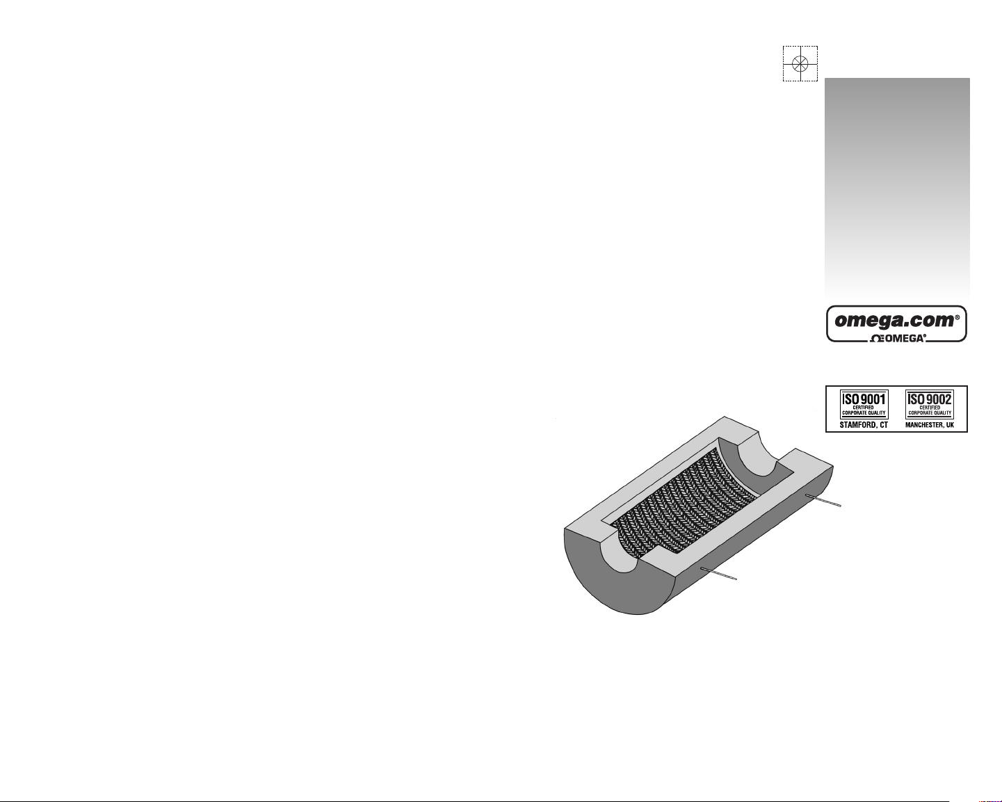
CRFC, CRWS, CRRS
and CRFP Series
Vacuum Formed Ceramic
Fiber Radiant Heaters
www.omega.com
e-mail: info@omega.com
User’s Guide
Shop online at
Where Do I Find Everything I Need for
Process Measurement and Control?
OMEGA…Of Course!
Shop online at www.omega.com
TEMPERATURE
Thermocouple, RTD & Thermistor Probes, Connectors, Panels &
Assemblies
Wire: Thermocouple, RTD & Thermistor
Calibrators & Ice Point References
Recorders, Controllers & Process Monitors
Infrared Pyrometers
PRESSURE, STRAIN AND FORCE
Transducers & Strain Gages
Load Cells & Pressure Gages
Displacement Transducers
Instrumentation & Accessories
FLOW/LEVEL
Rotameters, Gas Mass Flowmeters & Flow Computers
Air Velocity Indicators
Turbine/Paddlewheel Systems
Totalizers & Batch Controllers
pH/CONDUCTIVITY
pH Electrodes, Testers & Accessories
Benchtop/Laboratory Meters
Controllers, Calibrators, Simulators & Pumps
Industrial pH & Conductivity Equipment
DATA ACQUISITION
Data Acquisition & Engineering Software
Communications-Based Acquisition Systems
Plug-in Cards for Apple, IBM & Compatibles
Datalogging Systems
Recorders, Printers & Plotters
HEATERS
Heating Cable
Cartridge & Strip Heaters
Immersion & Band Heaters
Flexible Heaters
Laboratory Heaters
ENVIRONMENTAL
MONITORING AND CONTROL
Metering & Control Instrumentation
Refractometers
Pumps & Tubing
Air, Soil & Water Monitors
Industrial Water & Wastewater Treatment
pH, Conductivity & Dissolved Oxygen Instruments
M1187/0802
Page 2
Servicing North America:
USA: One Omega Drive, Box 4047
ISO 9001 Certified Stamford CT 06907-0047
Tel: (203) 359-1660 FAX: (203) 359-7700
e-mail: info@omega.com
Canada: 976 Bergar
Laval (Quebec) H7L 5A1
Tel: (514) 856-6928 FAX: (514) 856-6886
e-mail: info@omega.ca
For immediate technical or application assistance:
USA and Canada: Sales Service: 1-800-826-6342 / 1-800-TC-OMEGA
®
Customer Service: 1-800-622-2378 / 1-800-622-BEST
®
Engineering Service: 1-800-872-9436 / 1-800-USA-WHEN
®
TELEX: 996404 EASYLINK: 62968934 CABLE: OMEGA
Mexico: En Espan˜ol: (001) 203-359-7803 e-mail: espanol@omega.com
FAX: ( 001) 203-359-7807 info@omega.com.mx
Servicing Europe:
Benelux: Postbus 8034, 1180 LA Amstelveen, The Netherlands
Tel: +31 (0)20 3472121 FAX: +31 (0)20 6434643
Toll Free in Benelux: 0800 0993344
e-mail: sales@omegaeng.nl
Czech Republic: Rudé armády 1868, 733 01 Karviná 8
Tel: +420 (0)69 6311899 FAX: +420 (0)69 6311114
Toll Free: 0800-1-66342 e-mail: info@omegashop.cz
France: 11, rue Jacques Cartier, 78280 Guyancourt, France
Tel: +33 (0)1 61 37 29 00 FAX: +33 (0)1 30 57 54 27
Toll Free in France: 0800 466 342
e-mail: sales@omega.fr
Germany/Austria: Daimlerstrasse 26, D-75392 Deckenpfronn, Germany
Tel: +49 (0)7056 9398-0 FAX: +49 (0)7056 9398-29
Toll Free in Germany: 0800 639 7678
e-mail: info@omega.de
United Kingdom: One Omega Drive, River Bend Technology Centre
ISO 9002 Certified Northbank, Irlam, Manchester
M44 5BD United Kingdom
Tel: +44 (0)161 777 6611 FAX: +44 (0)161 777 6622
Toll Free in United Kingdom: 0800-488-488
e-mail: sales@omega.co.uk
OMEGAnet®Online Service Internet e-mail
www.omega.com info@omega.com
It is the policy of OMEGA to comply with all worldwide safety and EMC/EMI regulations that
apply. OMEGA is constantly pursuing certification of its products to the European New Approach
Directives. OMEGA will add the CE mark to every appropriate device upon certification.
The information contained in this document is believed to be correct, but OMEGA Engineering, Inc. accepts
no liability for any errors it contains, and reserves the right to alter specifications without notice.
WARNING: These products are not designed for use in, and should not be used for, patient-connected applications.
WARRANTY/DISCLAIMER
OMEGA ENGINEERING, INC. warrants this unit to be free of defects in materials and
workmanship for a period of 13 months from date of purchase. OMEGA’s Warranty
adds an additional one (1) month grace period to the normal
one (1) year product
warranty to cover handling and shipping time. This ensures that OMEGA’s
customers receive maximum coverage on each product.
If the unit malfunctions, it must be returned to the factory for evaluation. OMEGA’s
Customer Service Department will issue an Authorized Return (AR) number immediately upon phone or written request. Upon examination by OMEGA, if the unit is found to
be defective, it will be repaired or replaced at no charge. OMEGA’s WARRANTY does
not apply to defects resulting from any action of the purchaser, including but not limited to mishandling, improper interfacing, operation outside of design limits, improper
repair, or unauthorized modification. This WARRANTY is VOID if the unit shows evidence of having been tampered with or shows evidence of having been damaged as a
result of excessive corrosion; or current, heat, moisture or vibration; improper specification; misapplication; misuse or other operating conditions outside of OMEGA’s control. Components which wear are not warranted, including but not limited to contact
points, fuses, and triacs.
OMEGA is pleased to offer suggestions on the use of its various products.
However, OMEGA neither assumes responsibility for any omissions or errors nor
assumes liability for any damages that result from the use of its products in
accordance with information provided by OMEGA, either verbal or written.
OMEGA warrants only that the parts manufactured by it will be as specified and
free of defects. OMEGA MAKES NO OTHER WARRANTIES OR REPRESENTATIONS OF ANY KIND WHATSOEVER, EXPRESS OR IMPLIED, EXCEPT THAT OF
TITLE, AND ALL IMPLIED WARRANTIES INCLUDING ANY WARRANTY OF MERCHANTABILITY AND FITNESS FOR A PARTICULAR PURPOSE ARE HEREBY DISCLAIMED. LIMITATION OF LIABILITY: The remedies of purchaser set forth herein
are exclusive, and the total liability of OMEGA with respect to this order, whether
based on contract, warranty, negligence, indemnification, strict liability or otherwise, shall not exceed the purchase price of the component upon which liability
is based. In no event shall OMEGA be liable for consequential, incidental or special damages.
CONDITIONS: Equipment sold by OMEGA is not intended to be used, nor shall it be
used: (1) as a “Basic Component” under 10 CFR 21 (NRC), used in or with any nuclear
installation or activity; or (2) in medical applications or used on humans. Should any
Product(s) be used in or with any nuclear installation or activity, medical application,
used on humans, or misused in any way, OMEGA assumes no responsibility as set
forth in our basic WARRANTY/ DISCLAIMER language, and, additionally, purchaser will
indemnify OMEGA and hold OMEGA harmless from any liability or damage
whatsoever arising out of the use of the Product(s) in such a manner.
RETURN REQUESTS/INQUIRIES
Direct all warranty and repair requests/inquiries to the OMEGA Customer Service
Department. BEFORE RETURNING ANY PRODUCT(S) TO OMEGA, PURCHASER
MUST OBTAIN AN AUTHORIZED RETURN (AR) NUMBER FROM OMEGA’S
CUSTOMER SERVICE DEPARTMENT (IN ORDER TO AVOID PROCESSING DELAYS).
The assigned AR number should then be marked on the outside of the return package
and on any correspondence.
The purchaser is responsible for shipping charges, freight, insurance and proper
packaging to prevent breakage in transit.
FOR
WARRANTY RETURNS, please have
the following information available
BEFORE contacting OMEGA:
1. Purchase Order number under which
the product was PURCHASED,
2. Model and serial number of the product
under warranty, and
3. Repair instructions and/or specific
problems relative to the product.
FOR NON-WARRANTY REPAIRS,
consult
OMEGA for current repair charges. Have
the following information available
BEFORE contacting OMEGA:
1. Purchase Order number to cover the
COST of the repair,
2. Model and serial number of the product,
and
3. Repair instructions and/or specific
problems relative to the product.
OMEGA’s policy is to make running changes, not model changes, whenever an improvement is possible.
This affords our customers the latest in technology and engineering.
OMEGA is a registered trademark of OMEGA ENGINEERING, INC.
© Copyright 2002 OMEGA ENGINEERING, INC. All rights reserved. This document may not be copied,
photocopied, reproduced, translated, or reduced to any electronic medium or machine-readable form, in
whole or in part, without the prior written consent of OMEGA ENGINEERING, INC.
Page 3

i
CRFC, CRWS, CRRS, and CRFP Series
Vacuum Formed Ceramic Fiber Radiant Heaters
Page
Section 1 Introduction . . . . . . . . . . . . . . . . . . . . . . . . . . . . . . .1
1.1 General Description . . . . . . . . . . . . . . . . . . . . . . . . . . . . . . . . . . . 1
1.2 Recommended Maximum Operating Temperature . . . . . . . . 1
1.3 Tolerance . . . . . . . . . . . . . . . . . . . . . . . . . . . . . . . . . . . . . . . . . . . . . 1
Section 2 Unpacking . . . . . . . . . . . . . . . . . . . . . . . . . . . . . . . .1
Section 3 Wiring Procedures . . . . . . . . . . . . . . . . . . . . . . . . . .2
3.1 General . . . . . . . . . . . . . . . . . . . . . . . . . . . . . . . . . . . . . . . . . . . . . . 2
3.2 Heating Element Power Connection . . . . . . . . . . . . . . . . . . . . . 2
Section 4 Specifications . . . . . . . . . . . . . . . . . . . . . . . . . . . . . .5
4.1 General . . . . . . . . . . . . . . . . . . . . . . . . . . . . . . . . . . . . . . . . . . . . . . 5
4.2 Average Heat-up Rate . . . . . . . . . . . . . . . . . . . . . . . . . . . . . . . . . 5
4.3 CRFC Series . . . . . . . . . . . . . . . . . . . . . . . . . . . . . . . . . . . . . . . . . . 6
4.4 CRWS Series . . . . . . . . . . . . . . . . . . . . . . . . . . . . . . . . . . . . . . . . . . 8
4.5 CRRS Series . . . . . . . . . . . . . . . . . . . . . . . . . . . . . . . . . . . . . . . . . . 10
4.6 CRFP Series . . . . . . . . . . . . . . . . . . . . . . . . . . . . . . . . . . . . . . . . . . 12
TABLE OF
CONTENTS
14
Notes
Page 4

13ii
Notes
4.6 CRFP Series (Continued)
Without
All Dimensions in Inches Flange
Watts Volts A Dim B Dim $ C Dim D Dim Part Number #
300 60 6 4 2 8 CRFP-64/60
600 120 12 4 2 8 CRFP-124/120
400 60 6 6 2 10 CRFP-66/60
800 120 12 6 2 10 CRFP-126/120
1250 120 18 6 2 10 CRFP-186/120
1650 240 24 6 2 10 CRFP-246/240
1100 120 12 8 2 12 CRFP-128/120
1650 240 18 8 2 12 CRFP-188/240
2200 240 24 8 2 12 CRFP-248/240
1375 240 12 10 2 14 CRFP-1210/240
2050 240 18 10 2 14 CRFP-1810/240
2750 240 24 10 2 14 CRFP-2410/240
3400 240 30 10 2 14 CRFP-3010/240
1650 240 12 12 2 16 CRFP-1212/240
2460 240 18 12 2 16 CRFP-1812/240
3280 240 24 12 2 16 CRFP-2412/240
4100 240 30 12 2 16 CRFP-3012/240
3700 240 18 18 2 22 CRFP-1818/240
5000 240 24 18 2 22 CRFP-2418/240
6200 240& 30 18 2 22 CRFP-3018/240
$ Add 4" for units with flanges (forms new “D” dimension)
& Dual 240VAC circuits
Page 5

112
SECTION 1 INTRODUCTION
1.1 Description
The OMEGALUXTMCRFC, CRWS, CRRS, and CRFP Series of vacuum
formed ceramic heaters are produced using high quality, high purity,
vacuum formed ceramic with a low sodium inorganic bond. In the
CRRS and CRFP Series, helically wound quality iron-chrome-aluminum
ribbon elements are mounted in ridges which permit heat dissipation in
three directions, thereby, transferring more radiant heat energy to the
work chamber and load. By using this grooved surface, these
OMEGALUX products can more than triple the effective radiant surface.
Sections 4.3 through 4.6 show the different types of heaters that are
available from OMEGALUX as well as their specifications.
1.2 Recommended Maximum Operating Temperature
Maximum operating temperature is limited to 1800 degrees F degrees
C. For more information refer to the material safety data sheet
(MSDS-0135).
1.3 Tolerance
Because of the nature of ceramic fiber, there will be a potential variance
of ±1/4" in the size of the heaters. These products initially may shrink at
higher temperatures. This shrinkage could be up to 4% for temperatures
up to 980˚ C, resistance tolerance is ±5%.
SECTION 2 UNPACKING
Remove the Packing list and verify that all equipment has been
received. If there are any questions about the shipment, please call the
OMEGALUX Customer Service Department at 1-800-622-2378.
Upon receipt of shipment, inspect the container and equipment for any
signs of damage. Take particular note of any evidence of rough handling
in transit. Immediately report any damage to the shipping agent.
FOR YOUR INFORMATION
Care must be taken in handling the vacuum formed
ceramic heaters due to the materials used in
manufacturing them.
4.6 CRFP Series
Flat Plate – Without Flanges
(Surface is fully heated)
Flat Plate – With Unheated Flanges
Add (-C) to Part Number
Page 6

SECTION 3 WIRING PROCEDURES
3.1 General
1. Be sure that the line voltage matches the heater’s rated voltage.
2. Electric wiring to heater must be installed in accordance with Local
and National Electric Code.
3.2 Heating Element Power Connection
1. Figures 3-1, 3-2, 3-3, and 3-4 should be closely adhered to, to insure
maximum element life. L1 and L2 indicate the two power input
wires from the user’s power source. Polarity MUST always be
observed. L1 and L2 should never be connected adjacent to each
other. Failure to observe polarity may cause premature heater
failure.
2.
Recommended are mechancial terminations such as SPLIT BOLT
connections or TERMINAL STRIPS. For the all heating element
listed in this manual, the wire leads become brittle after being
brought up to maximum operating temperature (980˚ C). Caution
should be taken in handling heaters after initial operation.
3. Lead wire extending from the heater elements may be bent to
form to your specific needs. Caution must be taken so that the
integrity of the internal connection is maintained to prolong the
life of the heating element. To avoid placing excessive stress on
this junction, use soft nose pliers to hold the lead wire secure
where the wire exits from the heating element and then bend.
112
CAUTION AND WARNING!!
Fire and electrical shock may result if products are used
improperly or installed or used by non-qualified persons.
Refer to the inside front cover for additional warranty
information. The CR Series heaters are intended for
RADIANT heat only.
NEVER LET MATERIAL COME INTO
DIRECT CONTACT WITH THE FACE OF THE HEATER.
NOTE: The carrier will not honor any claims unless all shipping material is saved for
their examination. After examining and removing contents, save packing material and
carton in the event reshipment is necessary.
4.5 CRRS Series (Continued)
Without
All Dimensions in Inches Vestibules
Watts Volts A Dim* B Dim C Dim D Dim Part Number #
800 120 6 11 7 5 CRRS-67/120
1600 240 12 11 7 5 CRRS-127/240
2400 240 18 11 7 5 CRRS-187/240
3200 240 24 11 7 5 CRRS-247/240
900 120 6 12 8 6 CRRS-68/120
1800 240 12 12 8 6 CRRS-128/240
2700 240 18 12 8 6 CRRS-188/240
3600 240 24@ 12 8 6 CRRS-248/240
2250 240 12 14 10 8 CRRS-1210/240
3375 240 18 14 10 8 CRRS-1810/240
4500 240 24@ 14 10 8 CRRS-2410/240
2700 240 12 16 12 10 CRRS-1212/240
4050 240 18 16 12 10 CRRS-1812/240
5400 240 24@ 16 12 10 CRRS-2412/240
3400 240 12 19 15 13 CRRS-1215/240
5100 240 18 19 15 13 CRRS-1815/240
6800 240& 24@ 19 15 13 CRRS-2415/240
4100 240 12 22 18 16 CRRS-1218/240
6150 240& 18 22 18 16 CRRS-1818/240
8200 240& 24@ 22 18 16 CRRS-2418/240
4750 240 12 25 21 19 CRRS-1221/240
7125 240& 18 25 21 19 CRRS-1821/240
9500 240& 24@ 25 21 19 CRRS-2421/240
* Add 3 inches to “A” dimension for units with vestibules
# Unit with “-C” complete with vestibules attached
& Dual 240VAC circuits
@ Using two 12" long heaters; the indicated wattage is the total of
two 12" heaters
Page 7

310
4.5 CRRS Series
Without Vestibules
(Full Length is Heated)
With Optional Unheated
Vestibules (-C)
Figure 3-1. Full Circle Wiring Diagram (Group A)
CRFC Series
Containing one coil per half circle
(2 wires extending from ends of each half)
Figure 3-2. Half Circle Wiring Diagram (Group B)
CRWS/CRRS Series
Page 8

94
4.4 CRWS Series (Continued)
Without
All Dimensions in Inches Vestibules
Watts Volts A Dim* B Dim C Dim D Dim Part Number #
300 60 6 4 2 1.5 CRWS-62/60
600 120 12 4 2 1.5 CRWS-122/120
900 120 18 4 2 1.5 CRWS-182/120
1200 240 24 4 2 1.5 CRWS-242/240
425 120 6 5 3 2 CRWS-63/120
850 120 12 5 3 2 CRWS-123/120
1275 240 18 5 3 2 CRWS-183/240
1700 240 24 5 3 2 CRWS-243/240
565 120 6 6 4 2.5 CRWS-64/120
1130 120 12 6 4 2.5 CRWS-124/120
1700 240 18 6 4 2.5 CRWS-184/240
2250 240 24 6 4 2.5 CRWS-244/240
650 120 6 9 5 3.5 CRWS-65/120
1300 240 12 9 5 3.5 CRWS-125/120
1950 240 18 9 5 3.5 CRWS-185/240
2600 240 24 9 5 3.5 CRWS-245/240
850 120 6 10 6 4 CRWS-66/120
1700 240 12 10 6 4 CRWS-126/240
2550 240 18 10 6 4 CRWS-186/240
3400 240& 24 10 6 4 CRWS-246/240
920 240 6 11 7 5 CRWS-67/240
1840 240 12 11 7 5 CRWS-127/240
2760 240 18 11 7 5 CRWS-187/240
3680 240& 24 11 7 5 CRWS-247/240
1100 240 6 12 8 6 CRWS-68/240
2200 240 12 12 8 6 CRWS-128/240
3300 240 18 12 8 6 CRWS-188/240
4400 240& 24@ 12 8 6 CRWS-248/240
2250 240 12 14 10 8 CRWS-1210/240
3400 240& 18 14 10 8 CRWS-1810/240
4500 240& 24@ 14 10 8 CRWS-2410/240
2700 240 12 16 12 10 CRWS-1212/240
4050 240& 18 16 12 10 CRWS-1812/240
5400 240& 24@ 16 12 10 CRWS-2412/240
3400 240& 12 19 15 13 CRWS-1215/240
5100 240& 18 19 15 13 CRWS-1815/240
6800 240& 24@ 19 15 13 CRW-2415/240
4100 240& 12 22 18 16 CRWS-1218/240
6150 240& 18 22 18 16 CRWS-1818/240
8200 240& 24@ 22 18 16 CRWS-2418/240
4750 240& 12 25 21 19 CRWS-1221/240
7125 240& 18 25 21 19 CRWS-1821/240
9500 240& 24@ 25 21 19 CRWS-2421/240
* Add 3 inches to “A” dimension for units with vestibules
# Units with “-C” complete with vestibules attached
& Dual 240VAC circuits
@ Using two 12" long heaters; the indicated wattage is the total of
two 12" heaters
Containing two coils per half circle
(4 wires extending from ends of each half)
Figure 3-3. Half Circle Wiring Diagram (Group C)
Dual 240VAC
Figure 3-4. Flat Heating Wiring Diagram (Group D)
CRFP Series
(4 Heating Elements Formed into an Oven)
Page 9

5
8
SECTION 4 SPECIFICATIONS
4.1 General
Voltage: 60, 120, 240VAC single and dual circuits
Wattage: 300 to 9500
Maximum Operating CRFC, CRWS Series: 980˚ C
Temperature: CRFP, CRRS Series: 980˚ C
Dimensions: see specific sections later on
4.2 Average Heat-up Rate
4.4 CRWS Series
Without Vestibules
(Full Length is Heated)
With Optional Unheated
Vestibules (-C)
With proper installation and proper amounts of insulation,
the average heat-up time can be reached as indicated.
Figure 4-1. Average Heat-up Rate
Page 10

76
4.3 CRFC Series (Continued)
Without
All Dimensions in Inches Vestibules
Watts Volts A Dim* B Dim C Dim D Dim Part Number #
220 60 6 3 0.75 0.25 CRFC-756/60
440 120 12 3 0.75 0.25 CRFC-7512/120
250 60 6 3 1 0.5 CRFC-16/60
500 120 12 3 1 0.5 CRFC-112/120
300 60 6 3 1.25 0.75 CRFC-1256/60
600 120 12 3 1.25 0.75 CRFC-12512/120
350 60 6 3.5 1.5 1 CRFC-156/60
350 120 12 3.5 1.5 1 CRFC-1512/120
435 120 6 4 2 1.5 CRFC-26/120
870 120 12 4 2 1.5 CRFC-212/120
700 115 6 5 3 2 CRFC-36/115
1400 240 12 5 3 2 CRFC-312/240
2100 240 18 5 3 2 CRFC-318/240
900 240 6 7 4 2.5 CRFC-46/240
1800 240 12 7 4 2.5 CRFC-412/240
2700 240 18 7 4 2.5 CRFC-418/240
1130 240 6 9 5 3.5 CRFC-56/240
2260 240 12 9 5 3.5 CRFC-512/240
3390 240& 18 9 5 3.5 CRFC-518/240
4520 240& 24 9 5 3.5 CRFC-524/240
1350 240 6 10 6 4.5 CRFC-66/240
2700 240& 12 10 6 4.5 CRFC-612/240
4000 240& 18 10 6 4.5 CRFC-618/240
* Add 3 inches to “A” dimension for overall heater length
# Units with “-C” complete with vestibules attached
& Dual 240VAC circuits
With Optional Unheated
Vestibules (-C)
4.3 CRFC Series
Without Vestibules
(Full Length is Heated)
 Loading...