

Omega Products CN1632 Installation Manual
http://www.omega.com
e-mail: info@omega.com
®
User’s Guide
CN1632 SERIES
T emperature & Pr ocess
Controllers
US
C
Servicing North America:
USA: One Omega Drive, Box 4047
ISO 9001 Certified Stamford, CT 06907-0047
Tel: (203) 359-1660 FAX: (203) 359-7700
e-mail: info@omega.com
Canada: 976 Bergar
Laval (Quebec) H7L 5A1
Tel: (514) 856-6928 FAX: (514) 856-6886
e-mail: info@omega.ca
For immediate technical or application assistance:
USA and Canada: Sales Service: 1-800-826-6342 / 1-800-TC-OMEGA
SM
Customer Service: 1-800-622-2378 / 1-800-622-BEST
SM
Engineering Service: 1-800-872-9436 / 1-800-USA-WHEN
SM
TELEX: 996404 EASYLINK: 62968934 CABLE: OMEGA
Mexico and
Latin America: Tel: (95) 800-826-6342 FAX: (95) 203-359-7807
En Espan˜ol: (95) 203-359-7803 e-mail: espanol@omega.com
Servicing Europe:
Benelux: Postbus 8034, 1180 LA Amstelveen, The Netherlands
Tel: (31) 20 6418405 FAX: (31) 20 6434643
Toll Free in Benelux: 06 0993344
e-mail: nl@omega.com
Czech Republic: ul.Rude armady 1868, 733 01 Karvina-Hranice
Tel: 420 (69) 6311899 FAX: 420 (69) 6311114
e-mail: czech@omega.com
France: 9, rue Denis Papin, 78190 Trappes
Tel: (33) 130-621-400 FAX: (33) 130-699-120
Toll Free in France: 0800-4-06342
e-mail: france@omega.com
Germany/Austria: Daimlerstrasse 26, D-75392 Deckenpfronn, Germany
Tel: 49 (07056) 3017 FAX: 49 (07056) 8540
Toll Free in Germany: 0130 11 21 66
e-mail: info@omega.de
United Kingdom: One Omega Drive, River Bend Technology Centre
ISO 9002 Certified Northbank,
Irlam, Manchester
Tel: 44 (161) 777-6611 FAX: 44 (161) 777-6622
Toll Free in the United Kingdom: 0800-488-488
e-mail: info@omega.co.uk
®
OMEGAnetSMOn-Line Service Internet e-mail
http://www.omega.com info@omega.com
It is the policy of OMEGA to comply with all worldwide safety and EMC/EMI regulations that
apply. OMEGA is constantly pursuing certification of its products to the European New Approach
Directives. OMEGA will add the CE mark to every appropriate device upon certification.
The information contained in this document is believed to be correct, but OMEGA Engineering, Inc. accepts
no liability for any errors it contains, and reserves the right to alter specifications without notice.
WARNING: These products are not designed for use in, and should not be used for, patient-connected applications.

This manual is intended for use in support of installation, commissioning
and configuration of the 1/32-DIN Temperature Indicator.
The procedures described in this manual should be undertaken only by
personnel competent and authorized to do so.
CAUTION:
Read This Manual!!
!
THE INTERNATIONAL HAZARD SYMBOL IS INSCRIBED ADJACENT TO
THE REAR CONNECTION TERMINALS. IT IS IMPORTANT TO READ
THIS MANUAL BEFORE INSTALLING OR COMMISSIONING THE UNIT.
2

Table of Contents
Page
Section 1 - Installation - Panel-Mounting
1.1 Unpacking the Instrument 5
1.2 Installing the Instrument in the Mounting Panel 6
Section 2 - Installation - Wiring Connections
2.1 Mains (Line) Supply 8
2.2 Low Voltage (24V AC/DC) Supply - Option 8
2.3 Thermocouple Input 9
2.4 RTD Inputs 9
2.5 DC Inputs 9
2.6 Relay Outputs (Output 2 & Output 3) 9
2.7 dc Pulse Output (Output 1) 10
2.8 RS485 Communications 10
Section 3 - Front Panel
3.1 Indicators 11
3.2 Keys 11
Section 4 - Instrument Configuration
4.1 Entry into Instrument Configuration Mode 13
4.2 Parameter Sequence 13
4.3 Exit from Instrument Configuration Mode 17
Section 5 - Operation Mode
5.1 Normal Operation (Yellow LED OFF) 19
Section 6 - Instrument Setup (Yellow LED ON)
6.1 Adjustment Ranges 21
6.2 Default V alues/Settings 21
Section 7 - Calibration Mode
7.1 Prerequisites 22
7.2 Entry into Calibration Mode 23
7.3 Calibration Procedure 24
7.4 Exiting Calibration Mode 25
3

Appendix
A - Product Specification 26
B - Order Matrix 31
Figures & Tables
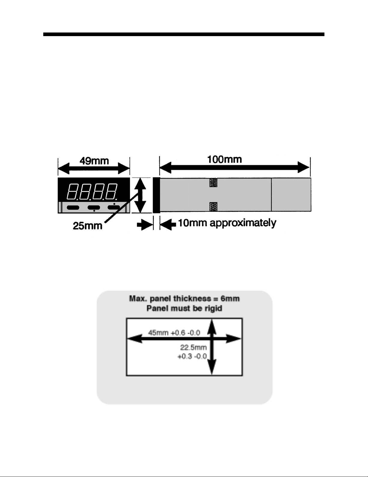
Figure 1-1 Main Dimensions 5
Figure 1-2 Panel Cut-out Dimensions 5
Figure 2-1 Rear Terminal Connections 7
Figure 2-2 Mains (Line) Supply Connections 8
Figure 2-3 Low Voltage AC/DC Supply Connections 9
Figure 2-4 RS485 Line Termination 10
Table 4-1 Sensor Selection Codes 16
Table 4-2 Output Selection Codes 16
4
Installation - Panel-Mounting
1.1 UNPACKING THE INSTRUMENT
1. Remove the Instrument from its packing. A panel gasket and a “no tools
required” fixing strap are supplied. Retain the packing for future use (e.g.
moving the Instrument to a different site).
2. Examine the delivered items for damage or deficiencies. If any are found,
notify the carrier immediately. Check that the Product Code on the label
affixed to the Instrument housing corresponds to that ordered.
FIGURE 1-1 Main Dimensions
FIGURE 1-2 Panel Cut-out Dimensions
5
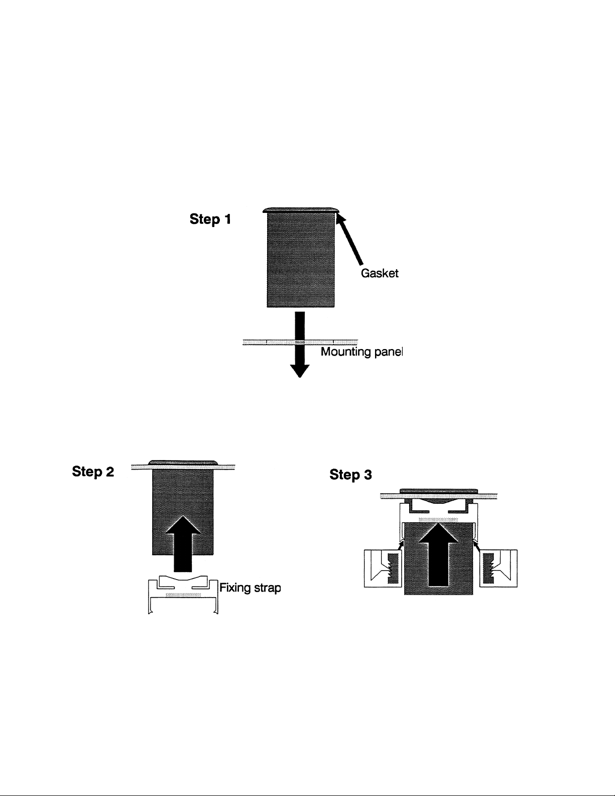
1. 2 INSTALLING THE INSTRUMENT IN THE MOUNTING PANEL
CAUTION: Do not remove the front panel gasket from the Instrument, as
this may cause inadequate clamping of the Instrument to the mounting
panel. Ensure that this gasket is not distorted and that the Instrument is
positioned squarely against the mounting panel. Apply pressure to the front
panel bezel only.
Instrument
6
Installation - Wiring Connections
dc Pulse
Line Supply
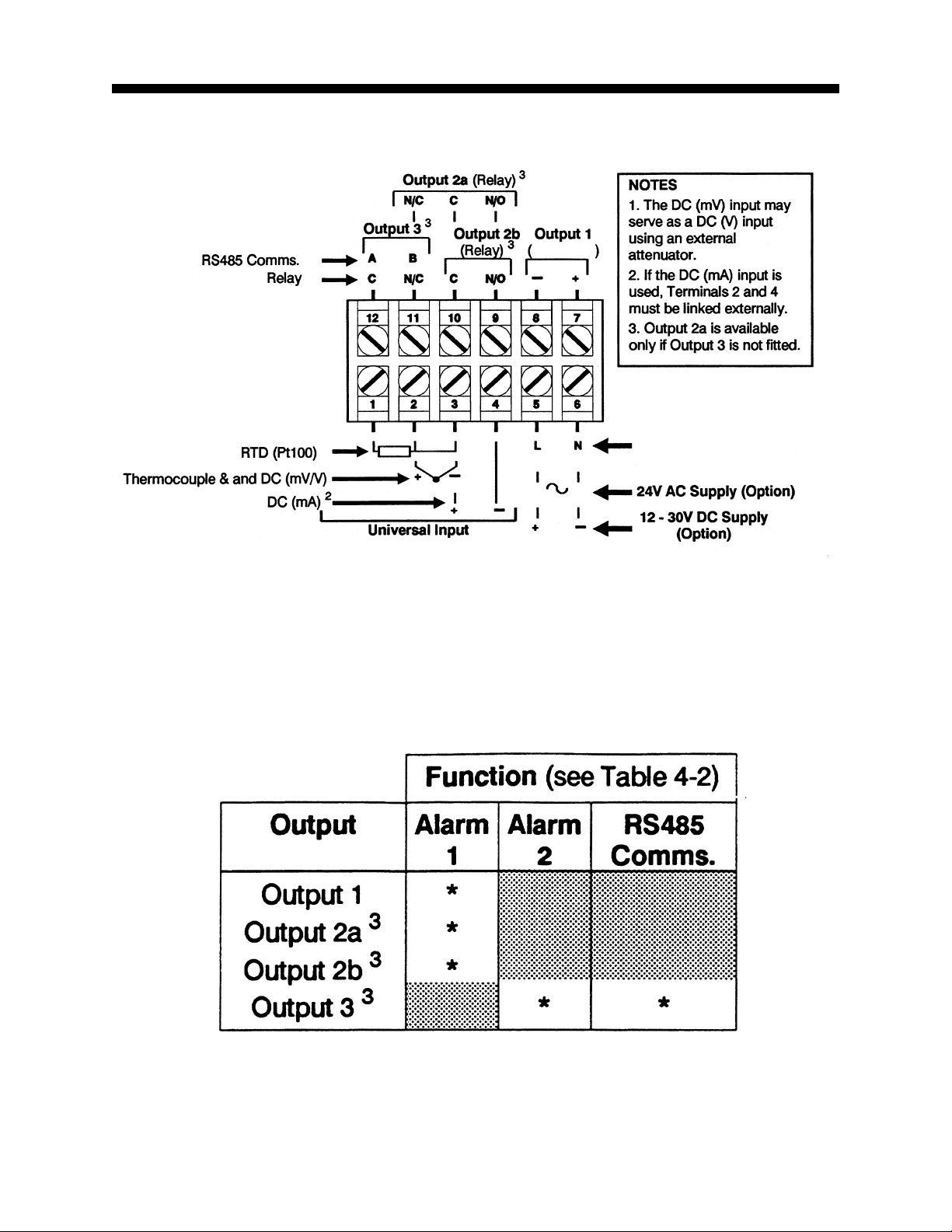
FIGURE 2-1 Rear Terminal Connections
NOTE: Terminals 7 & 8 are dedicated to those units which a dc Pulse output was ordered. If a
single output relay unit was ordered, the relay is wired between pins 9 & 10.
7
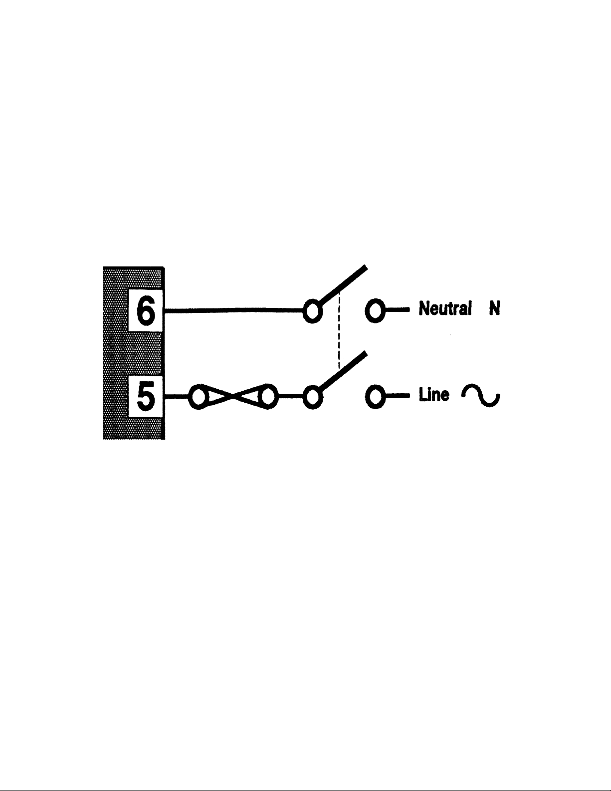
2.1 MAINS (LINE) SUPPLY
This version of the Instrument will operate on a 96 - 264V AC 50/60Hz
mains (line) supply. The power consumption is approximately 4W.
CAUTION: This equipment is designed for installation in an enclosure
which provides adequate protection against electric shock. Local
regulations regarding electrical installation should be rigidly observed.
Consideration should be given to prevention of access to the power
terminations by unauthorized personnel. Power should be connected via a
two-pole isolating switch (preferably situated near the Instrument) and a 1A
fuse, as shown in Figure 2-2.
FIGURE 2-2 Mains (Line) Supply Connections
If the contacts of the relay output(s) are used to carry mains (line) voltage, it
is recommended that the relay contacts mains (line) supply should be
switched and fused in a similar manner but should be separate from the
Instrument mains (line) supply.
2.2 LOW VOLTAGE (24V AC/DC) SUPPLY - OPTION
This version of the Instrument will operate on 12 - 24V AC 50/60Hz or 12 30V DC supply . The power consumption is approximately 4W. The
connections are shown in Figure 2-3; these should be made via a two-pole
isolating switch and a 315mA slow-blow (anti-surge Type T) fuse.
8
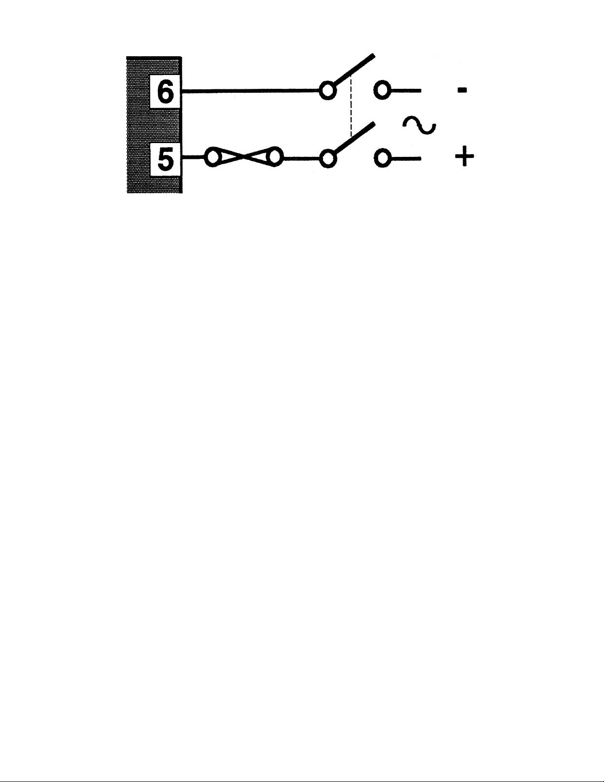
FIGURE 2-3 Low Voltage AC/DC Supply Connections
2.3 THERMOCOUPLE INPUT
The correct type of thermocouple extension leadwire or compensating cable
must be used for the full distance between the Instrument and the thermocouple, ensuring that the correct polarity is observed throughout.
NOTE: Do not run the thermocouple cables adjacent to power-carrying
conductors. If the wiring is run in a conduit, use a separate conduit for the
thermocouple wiring. If the thermocouple is grounded, this must be done at
one point only. If the thermocouple extension lead is shielded, the shield
must be grounded at one point only.
2.4 RTD INPUTS
The compensating lead should be connected to Terminal 3. For two-wire
RTD inputs, Terminals 2 and 3 should be linked. The extension leads should
be of copper and the resistance of the wires connecting the resistance
element should not exceed 5 ohms per lead (the leads should be of equal
length).
2.5 DC INPUTS
DC (mV) inputs are connected to Terminals 2 and 3 in the polarity shown in
Figure 2-1; DC (V) inputs are connected to the same terminals with the
same polarity but require an external attenuator. DC (mA) inputs are connected to Terminals 3 and 4 in the polarity shown in Figure 2-1 with Terminals 2 and 4 linked externally.
2.6 RELAY OUTPUTS (OUTPUT 2 & OUTPUT 3)
The contacts are rated at 2A resistive at 120/240V AC.
9
2.7 dc PULSE OUTPUT (OUTPUT 1)
This output produces a time-proportioned non-isolated DC signal (0 - 10V
nominal, into 500Ω minimum).
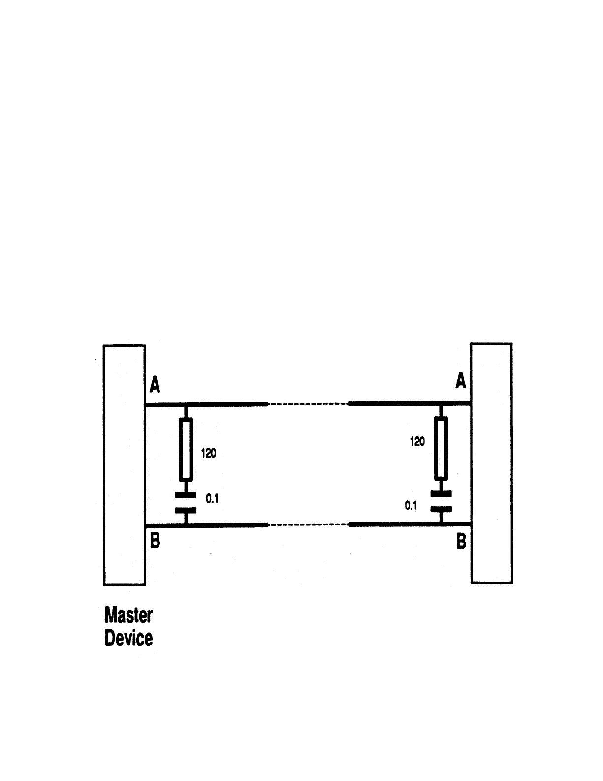
2.8 RS485 COMMUNICATIONS
The “A” terminal (Terminal 12) on the Instrument should be connected to
the “A” terminal on the master device; the “B” terminal (Terminal 11) on the
Instrument should be connected to the “B” terminal on the master device.
This instrument uses standard RS485 devices, isolated from all other inputs
and outputs. The devices present a 1/4-unit load to the RS485 line. Generally, termination will not be required but may be necessary for line lengths
greater than 100 metres. Where termination is necessary, it is recommended that a 120Ω resistance in series with a 0.1µF capacitor be used at
each end of the line (see Figure 2-4).
FIGURE 2-4 RS485 Line Termination
10
Instrument
 Loading...