

Omega Products CN1462 Installation Manual
www.omega.com
e-mail: info@omega.com
User’s Guide
CN1462
Controller
®
Shop online at

Servicing North America:
USA: One Omega Drive, P.O. Box 4047
ISO 9001 Certified Stamford CT 06907-0047
TEL: (203) 359-1660 FAX: (203) 359-7700
e-mail: info@omega.com
Canada: 976 Bergar
Laval (Quebec) H7L 5A1
TEL: (514) 856-6928 FAX: (514) 856-6886
e-mail: info@omega.ca
For immediate technical or application assistance:
USA and Canada: Sales Service: 1-800-826-6342 / 1-800-TC-OMEGA
®
Customer Service: 1-800-622-2378 / 1-800-622-BEST
®
Engineering Service: 1-800-872-9436 / 1-800-USA-WHEN
®
TELEX: 996404 EASYLINK: 62968934 CABLE: OMEGA
Mexico: En Espan˜ol: (001) 203-359-7803 e-mail: espanol@omega.com
FAX: (001) 203-359-7807 info@omega.com.mx
Servicing Europe:
Benelux: Postbus 8034, 1180 LA Amstelveen, The Netherlands
TEL: +31 (0)20 3472121 FAX: +31 (0)20 6434643
Toll Free in Benelux: 0800 0993344
e-mail: sales@omegaeng.nl
Czech Republic: Rudé armády 1868, 733 01 Karviná 8
TEL: +420 (0)69 6311899 FAX: +420 (0)69 6311114
Toll Free: 0800-1-66342 e-mail: info@omegashop.cz
France: 11, rue Jacques Cartier, 78280 Guyancourt, France
TEL: +33 (0)1 61 37 29 00 FAX: +33 (0)1 30 57 54 27
Toll Free in France: 0800 466 342
e-mail: sales@omega.fr
Germany/Austria: Daimlerstrasse 26, D-75392 Deckenpfronn, Germany
TEL: +49 (0)7056 9398-0 FAX: +49 (0)7056 9398-29
Toll Free in Germany: 0800 639 7678
e-mail: info@omega.de
United Kingdom: One Omega Drive, River Bend Technology Centre
ISO 9002 Certified Northbank, Irlam, Manchester
M44 5BD United Kingdom
TEL: +44 (0)161 777 6611 FAX: +44 (0)161 777 6622
Toll Free in United Kingdom: 0800-488-488
e-mail: sales@omega.co.uk
OMEGAnet®Online Service Internet e-mail
www.omega.com info@omega.com
It is the policy of OMEGA to comply with all worldwide safety and EMC/EMI regulations that
apply. OMEGA is constantly pursuing certification of its products to the European New Approach
Directives. OMEGA will add the CE mark to every appropriate device upon certification.
The information contained in this document is believed to be correct, but OMEGA Engineering, Inc. accepts
no liability for any errors it contains, and reserves the right to alter specifications without notice.
WARNING: These products are not designed for use in, and should not be used for, patient-connected applications.

Table of Contents
Section 1 - General Page
1.1 Product Description 1
Section 2 - Installation & Wiring
2.1 Unpacking Procedure 3
2.2 Panel Mounting 3
2.3 Preparation for Wiring 5
2.4 Input Connections 12
2.5 Output Connections 15
Section 3 - Operation
3.1 Power-up Procedure 23
3.2 Keypad Operation 23
3.3 Indicators 25
3.4 Displays 26
3.5 Alarm Status Indication 26
3.6 Viewing Operating Modes 27
3.7 Adjusting the Setpoint 27
3.8 Viewing Input Values 28
3.9 Base Mode/Off Mode Outputs 29
3.10 Viewing the Time and Day 29
3.11 Manual Control 29
3.12 Using the Pre-Tune Facility 30
3.13 Using the Self-Tune Facility 31
3.14 Enable Mode 32
Section 4 - Configuration
4.1 Entry into Configuration 34
4.2 Hardware Definition Mode 35
4.3 Configuration Mode Parameters 38
4.4 Exit from Configuration Mode 43
Section 5 - Tune Mode
5.1 Tune Parameters 45
5.2 Exiting Tune Mode 50
Section 6 - Alarm Mode
6.1 Alarm Parameters 51
6.2 Alarm Inhibit 55
6.3 Loop Alarm and Loop Alarm Time 55
i

Section 7 - Profile Define Mode
7.1 Entry into Profile Define 60
7.2 Parameters Common to All Profiles 61
7.3 Parameters which apply to a Specific Profile 64
7.4 Parameters in any/each Segment 68
7.5 Using Join, Repeat, and End Segments 71
7.6 Basic Rules to Remember 73
7.7 Exiting Program Define Mode 73
Section 8 - Programs
8.1 Selecting and Running a Program 74
8.2 Changing Timebase 74
8.3 Holding Manually 74
8.4 Jumping to Next Segment 75
8.5 Viewing Program Status 75
8.6 Aborting a Program 76
8.7 End of Progam Indication 76
8.8 Accessing Modes of the Controller 77
Section 9 - Test Mode 78
Section 10- Calibration Mode
10.1 Calibration Procedure 79
10.2 Exit From Calibration 82
10.3 Calibration Check 82
Appendices
A - Input Range Codes 83
B - Board Layout - Jumper positioning 85
Figure B-1 PCB Positions 85
Figure B-2 Output 2/Output 3 Removal 86
Figure B-3 CPU PWA 87
Figure B-4 PSU PWA with Relay or dc pulse Out.1 88
Figure B-5 PSU PWA with DC Output 1 89
Figure B-6 Option PWA DC Output 2/Output 3 90
C - Specifications 91
D - Model Number Hardware Matrix 100
E - Software Reference Sheet 101
ii

Figures
Figure 1-1 Front Panel 2
Figure 2-1 Panel Cut-Out Dimensions 3
Figure 2-2 Main Dimensions 4
Figure 2-3 Panel Mounting the controller 5
Figure 2-4 Noise Suppression 8
Figure 2-5 Noise Suppression 8
Figure 2-6 Rear Terminal Connections 10
Figure 2-6A Rear Terminal Connections 11
Figure 2-7 Main Supply 12
Figure 2-7A 24V Nominal AC/DC Supply 13
Figure 2-8 Thermocouple (T/C) Input 13
Figure 2-9 RTD Input 13
Figure 2-10 Volt, mV Input 14
Figure 2-11 mA DC Input 14
Figure 2-12 Remote Digital Communications 15
Figure 2-13 Relay Output 1 15
Figure 2-14 dc Pulse Output 1 15
Figure 2-15 mADC Output 1 16
Figure 2-16 Relay Output 2 16
Figure 2-17 dc Pulse Output 2 16
Figure 2-18 mADC Output 2 17
Figure 2-19 Transmitter Power Supply Out 2 17
Figure 2-20 Relay Output 3 17
Figure 2-21 dc Pulse Output 3 18
Figure 2-22 mADC Output 3 18
Figure 2-23 Transmitter Power Supply Out 3 18
Figure 2-24 End of Program Output 19
Figure 2-25 Event Outputs 19
Figure 2-26 Remote Program Output 20
Figure 2-27 Valve Motor Drive 21
Figure 2-28 VMD with Interlock 22
Figure 5-1 Proportional Band and Deadband/Overlap 49
Figure 6-1 Alarm Operation 57
Figure 6-2 Alarm Hysteresis Operation 59
Figure 7-1 Auto Hold Operation 67
Figure 10-1 Jumper Positions Calibration 81
Figure 10-2 Connections for Calibration 82
iii

iv

Section 1 - General
1.1 PRODUCT DESCRIPTION
This instrument is a powerful, easy-to-use 1/4 DIN setpoint programmer
with full PID control capability (complete with Self-Tune and Pre-Tune capabilities).
Its standard features include:
• Up to eight programs of up to 16 free-format (e.i. dwell, ramp, join, or
end) segments each.
• Facility to join programs to one another in any sequence (maximum
program length 121 segments)
• User can change currently-running program segment.
• Delayed Start of Program facility
• End of Program relay output
• Universal input-thermocouple, RTD (PT100) or DC linear user-selectable.
• Universal power supply (90 -264V AC 50/60 Hz)
• Configurable from front panel
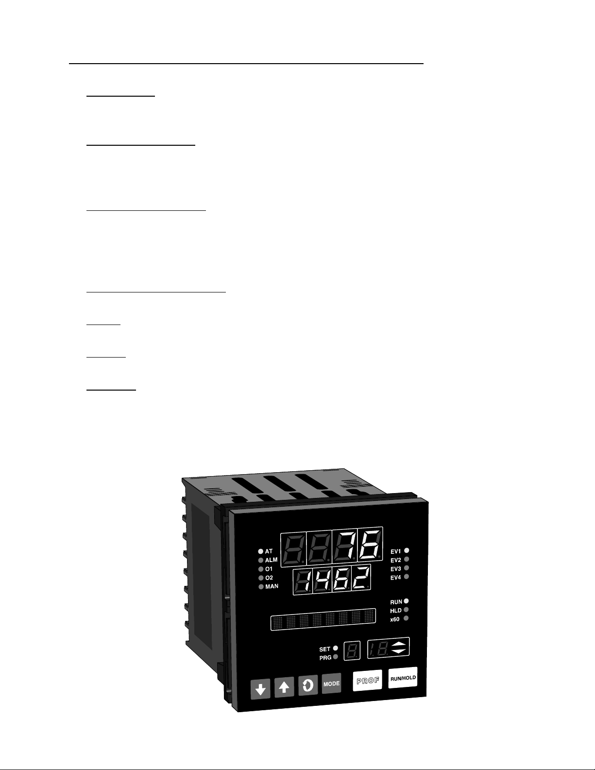
• Comprehensive front panel displays
• Front panel sealing to NEMA 4 standard
• Behind-panel depth only 100mm (3.94 inches)
• Power Failure Recovery
Optional features include:
• Remote control and selection of program (plug-in option)
• Up to four Event relay outputs (plug-in option)
• Second control output
• Recorder output (setpoint or process variable)
• RS-485 serial communications
• User-definable program tag names
• Support software (Off-line Configurator, On-line Graphic Program
Editor) - operates via RS-485 communications link.
• Real Time Clock
1
The Setpoint Programmer has numerous operating modes:
Base Mode: Day to day PID control operations with no program running.
In this mode, a program may be selected to run.
Profile Run Mode: A selected program is running, held or waiting for a
pre-defined delay before starting. In this mode, the operator can view
status and program information.
Profile Define Mode: Used to view/create/edit programs. this mode is
entered either from Base Mode (selected program may be edited/created) or from Program Run Mode (currently-running program may be
edited).
Controller Define Mode: Used to define the controller characteristics.
Tune: Used to adjust tuning parameters
Alarm: Used to define and set alarms
Enable: Provides a means of enabling or disabling access to setpoint
changes and each of the non-control modes.
FIGURE 1-1
Front Panel
2
Section 2 - Installation & Wiring
2.1 UNPACKING PROCEDURE
1. Remove the instrument from its packing. The instrument is supplied
with a panel gasket and push-fit strap. Retain the packing for future use,
should it be necessary to transport the instrument to a different site or
return it to the factory for repair/testing.
2. Examine the delivered items for damage or deficiencies. If any is
found, notify the carrier immediately. Check that the model number
shown on the label affixed to the instrument housing corresponds to that
ordered (see Appendix D).
2.2 PANEL-MOUNTING THE SETPOINT PROGRAMMER
The panel on which the instrument is to be mounted must be rigid and may
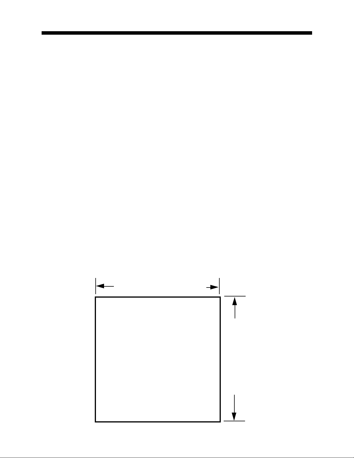
be up to 6.0 mm (.25 inches ) thick. The cutout required for a single instrument is shown in Figure 2-1.
FIGURE 2-1
Cut-Out Dimensions
92 mm +0.5 - 0.00
(3.62”+.020 - .000)
PANEL
CUTOUT
SIZE
92 mm + 0.5 - 0.0
(3.62” + .020 - .000)
3
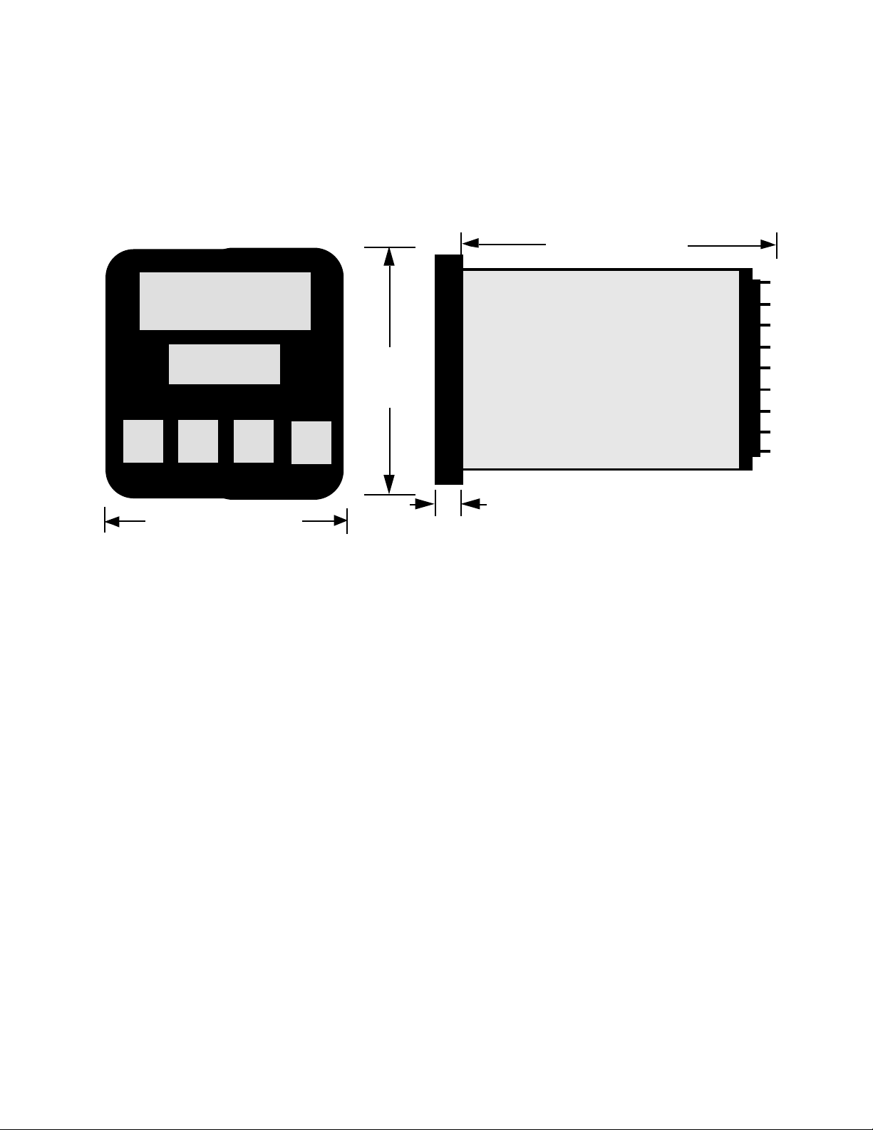
The main dimensions of the instrument are shown below.
FIGURE 2-2
Main Dimensions
100 mm (3.94 in.)
96 mm
(3.78 in)
Side View
96 mm
(3.78 in.)
Max. Panel Thickness 6.0mm (.25 inches)
10 mm (0.39 in.)
To panel-mount the instrument:
1. Insert the rear of the instrument housing through the cutout (from the
front of the mounting panel) and hold the instrument lightly in position
against the panel. Ensure that the panel gasket is not distorted and that
the instrument is positioned squarely against the mounting panel. Apply
pressure to the front panel bezel only.
Caution: Do not remove the panel gasket, as this may result
in inadequate clamping of the instrument in the panel.
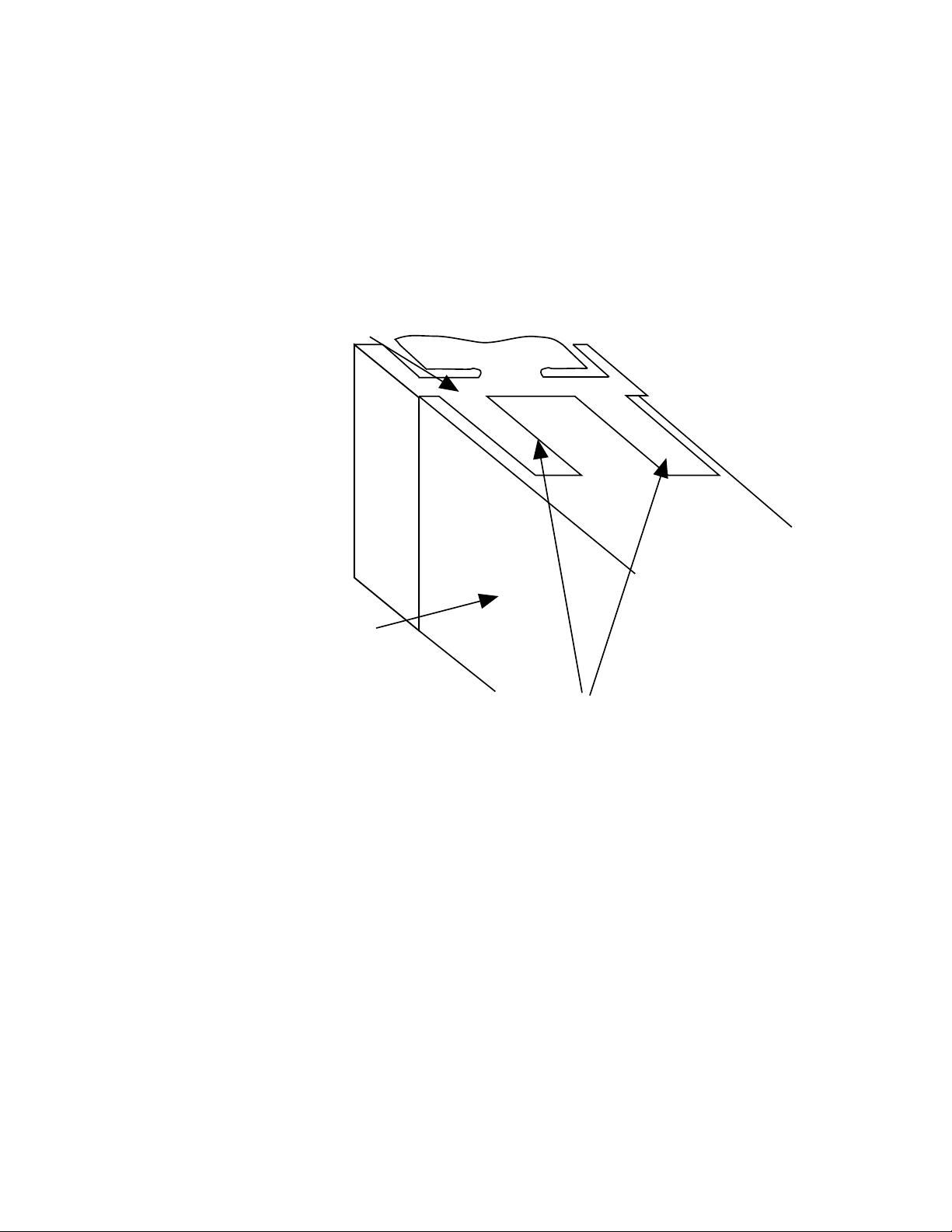
2. Slide the fixing strap in place (Figure 2-3) and push it forward until it
is firmly in contact with the rear face of the mounting panel (the tongues
on the strap should have engaged in matching rachet positions on the
instrument housing and the fixing strap springs should be pushing firmly
against the mounting panel rear face).
4
Once the instrument is installed in its mounting panel, it may be subsequently removed from its housing, if necessary, as described in Appendix B.
FIGURE 2-3
Panel-Mounting the Instrument
Mounting Clamp
Controller Housing
Tongues on mounting clamp engage in
ratchet slots on controller housing
2.3 PREPARATION FOR WIRING
Electrical noise is a phenomenon typical of industrial environments. The
following are guidelines that must be followed to minimize the effect of noise
upon any instrumentation.
2.3.1 INSTALLATION CONSIDERATIONS
Listed below are some of the common sources of electrical noise in the
industrial environment:
• Ignition Transformers
• Arc Welders
• Mechanical contact relay(s)
• Solenoids
5

Before using any instrument near the device listed, the instructions below
should be followed:
1. If the instrument is to be mounted in the same panel as any of the
listed devices, separate them by the largest distance possible. For
maximum electrical noise reduction, the noise generating devices should
be mounted in a separate enclosure.
2. If possible, eliminate mechanical contact relay(s) and replace with
solid state relays. If a mechanical relay being powered by an instrument
output device cannot be replaced, a solid state relay can be used to
isolate the instrument.
3. A separate isolation transformer to feed only instrumentation should
be considered. The transformer can isolate the instrument from noise
found on the AC power input.
4. If the instrument is being installed on existing equipment, the wiring in
the area should be checked to insure that good wiring practices have
been followed.
2.3.2 AC POWER WIRING
Neutral (For 115 VAC)
It is good practice to assure that the AC neutral is at or near ground potential. To verify this, a voltmeter check between neutral and ground should be
done. On the AC range, the reading should not be more than 50 millivolts.
If it is greater than this amount, the secondary of this AC transformer supplying the instrument should be checked by an electrician. A proper neutral
will help ensure maximum performance from the instrument.
2.3.3 WIRE ISOLATION
Four voltage levels of input and output wiring may be used with the unit:
• Analog input or output (i.e. thermocouple, R TD, VDC, mVDC, or
mADC)
• SPDT Relays
• SSR driver outputs
• AC power
6

The only wires that should run together are those of the same category. If
they need to be run parallel with any of the other lines, maintain a minimum
6 inch space between wires. If wires must cross each other, do so at 90
degrees. This will minimize the contact with each other and reduces "cross
talk". "Cross Talk" is due to the EMF (Electro Magnetic Flux) emitted by a
wire as current passes through it. This EMF can be picked up by other
wires running in the same bundle or conduit.
In applications where a High Voltage Transformer is used (i.e. ignition systems) the secondary of the transformer should be isolated from all other
cables.
This instrument has been designed to operate in noisy environments, however, in some cases even with proper wiring it may be necessary to suppress the noise at the source.
2.3.4 USE OF SHIELDED CABLE
Shielded cable helps eliminate electrical noise being induced on the wires.
All analog signals should be run with shielded cable. Connection lead
length should be kept as short as possible, keeping the wires protected by
the shielding. The shield should be grounded at one end only. The preferred grounding location is the sensor, transmitter, or transducer.
2.3.5 NOISE SUPPRESSION AT THE SOURCE
Usually when good wiring practices are followed no further noise protection
is necessary. Sometimes in severe electrical environments, the amount of
noise is so great that it has to be suppressed at the source. Many manufacturers of relays, contactors, etc. supply "surge suppressors" which
mount on the noise source.
For those devices that do not have surge suppressors supplied. RC (resistance-capacitance) networks and/or MOV (metal oxide varistors) may be
added.
Inductive Coils - MOV's are recommended for transient suppression in
inductive coils connected in parallel and as close as possible to the coil.
See Figure 2-4. Additional protection may be provided by adding an RC
network across the MOV.
7
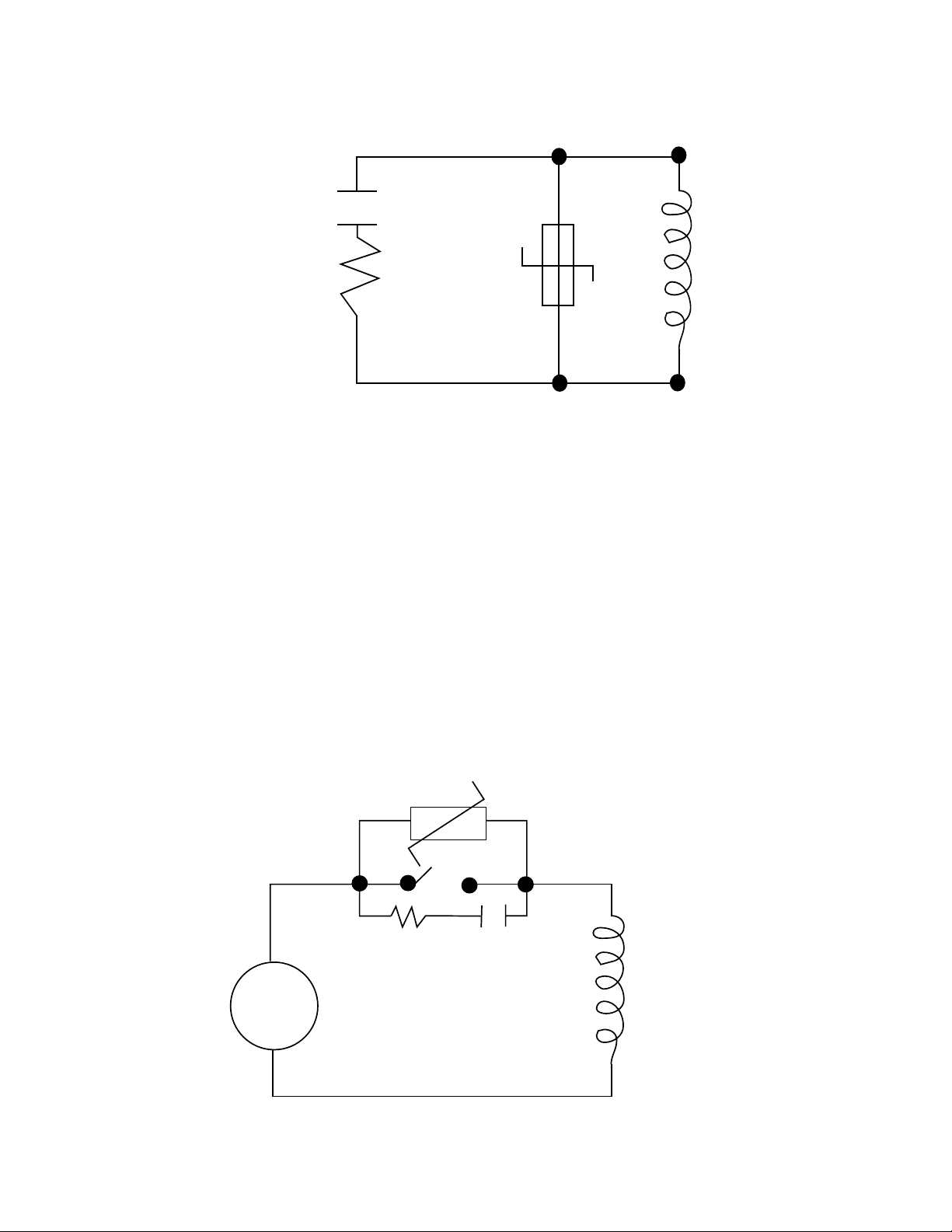
FIGURE 2-4
0.5
mfd
1000V
115V 1/4W
230V 1W
220
ohms
Inductive
Coil
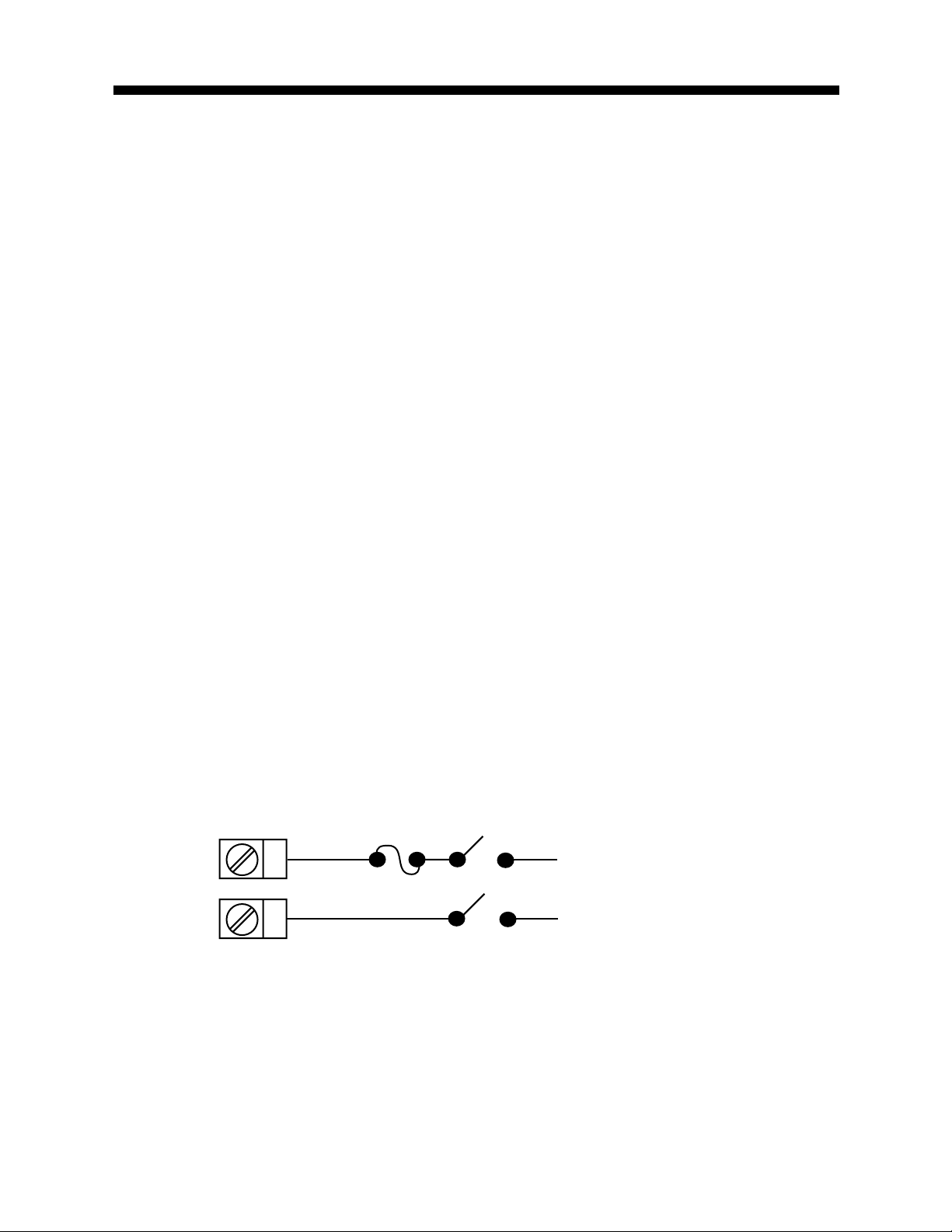
Contacts - Arcing may occur across contacts when the contact opens and
closes. This results in electrical noise as well as damage to the contacts.
Connecting a RC network properly sized can eliminate this arc.
For circuits up to 3 amps, a combination of a 47 ohm resistor and 0.1 microfarad capacitor (1000 volts) is recommended. For circuits from 3 to 5
amps, connect 2 of these in parallel. See Figure 2-5, below.
FIGURE 2-5
AC
MOV
R C
Inductive
Coil
8

2.3.5 SENSOR PLACEMENT (THERMOCOUPLE OR RTD)
Two wire RTD's should be used only with lead lengths less than 10 feet.
If the temperature probe is to be subjected to corrosive or abrasive condi-
tions, it should be protected by the appropriate thermowell. The probe
should be positioned to reflect true process temperature:
In liquid media - the most agitated area
In air - the best circulated area
9
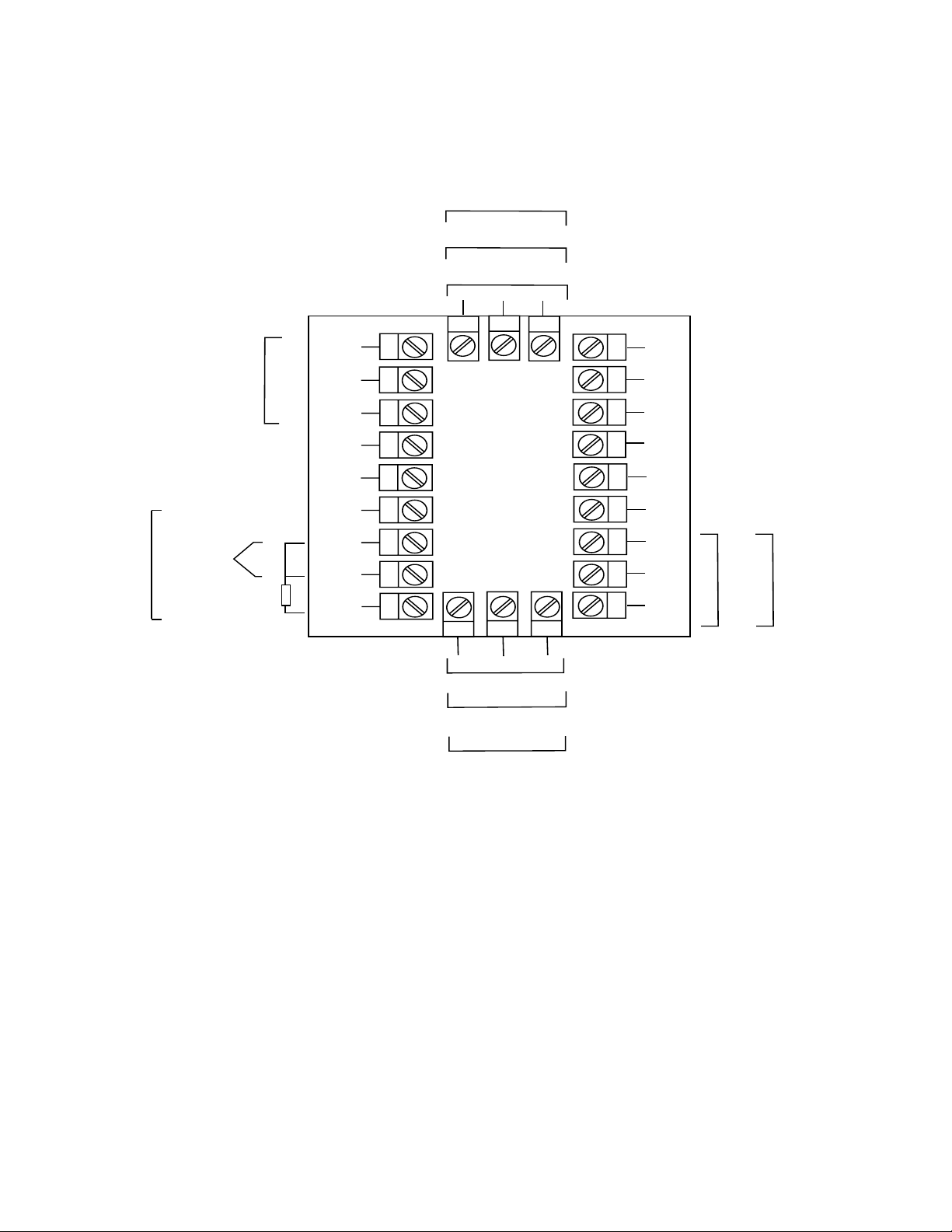
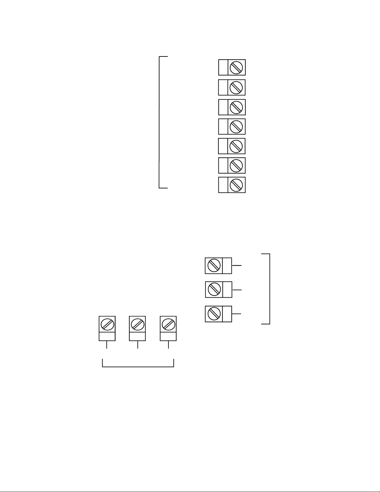
FIGURE 2-6
Rear Terminal Connections
END OF
PROGRAM
OUTPUT
+
INPUT
Linear (mA)
-
N/O
N/C
-
+
+
RTD
Linear (V/mV)
Thermocouple
Transmitter Power Supply
9
C
8
7
6
5
4
3
2
1
OUTPUT 3
-
Relay
N/C
dc Pulse
-
11
23 22
24
+
N/OC
+
MAINS (LINE)
L
N
B
A
COM
-
+
SUPPLY
24V 24V
-
AC DC
+
RS485
SERIAL
COMMS.
N/C
C
dc Pulse
N/O
Relay
OUTPUT 1
1210
13
14
15
16
17
18
19
20
21
+
dc Pulse
N/O
C
Relay
+
Transmitter Power Supply
Output 2
-
N/C
-
10
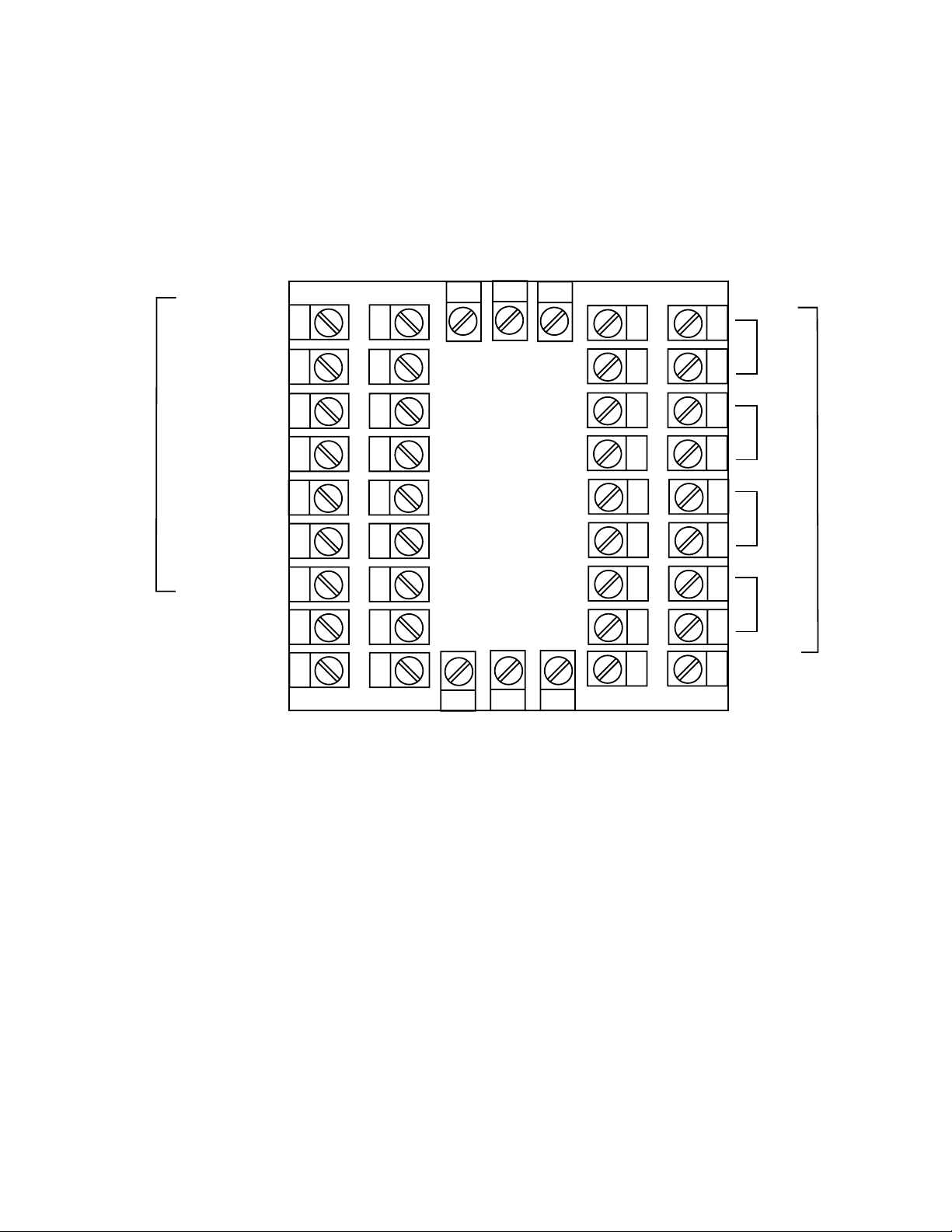
FIGURE 2-6A
RESET
RUN/HOLD
REMOTE INPUTS
X60 (FAST)
R0
R1
R2
C
33
32
31
30
29
28
27
26
25
34
#1
35
36
#2
37
38
#3
39
EVENT OUTPUTS
40
#4
41
42
11
2.4 Input Connections
In general, all wiring connections are made to the instrument after it is installed. Avoid electrical shock. AC power wiring must not be connected to
the source distribution panel until all wiring connection procedures are
completed.
Caution: This equipment is designed for installation in an
enclosure which provide adequate protection against electric shock. Local regulations regarding electrical installation should be rigidly observed. Consideration should be
given to prevention of access to the power terminations by
unauthorized personnel. Power should be connected via a
two pole isolating switch (preferably situated near the
equipment) and a 1 A fuse, as shown in Figure 2-7.
FIGURE 2-7
Main Supply
The instrument will operate on 90-264V ac 50/60 Hz mains (line) supply.
The power consumption is approximately 4 VA. If the instrument has relay
outputs in which the contacts are to carry mains (line) voltage, it is recommended that the relay contact mains (line) supply should be switched and
fused in a similar manner but should be separate from the instrument
mains (line) supply.
13
14
L
N
Line
Neutral
12
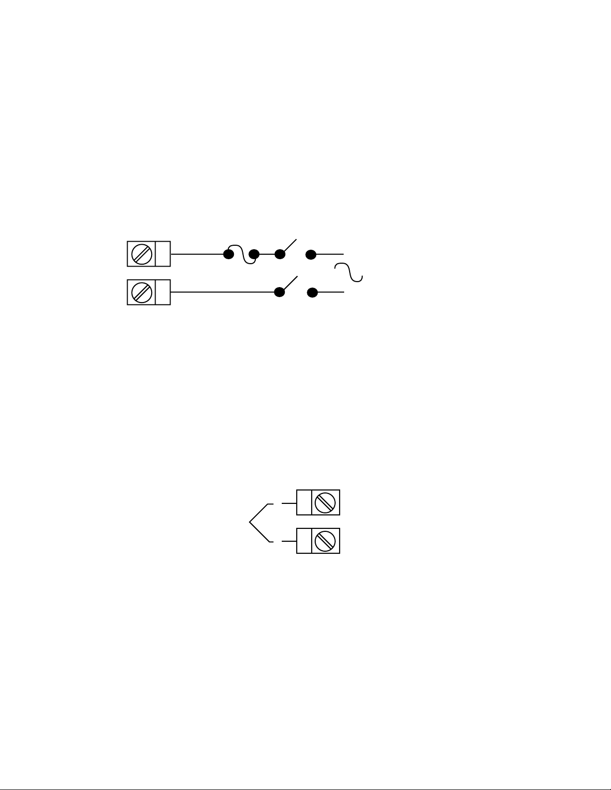
FIGURE 2-7A
24V Nominal ac/dc Supply
The supply connection for the 24V AC/DC option of the instrument are as
shown below. Power should be connected via a two pole isolating switch
and a 315 mA slow -blow (anti-surge type T) fuse. With the 24V AC/DC
supply option fitted, these terminals will accept the following supply voltage
ranges:
24V (nominal) ac 50/60Hz - 20-50V
24V (nominal) dc - 22-65V
L
13
14
N
24V ac
50/60Hz
-
24V dc
+
FIGURE 2-8
Thermocouple (T/C) Input
Make the thermocouple connections as illustrated below. Connect the
positive leg of the thermocouple to terminal 2 and the negative leg to
terminal 3.
-
+
Thermocouple
FIGURE 2-9
RTD Input
Make RTD connections as illustrated below. For a three wire RTD, connect the resistive leg of the RTD to terminal 1 and the common legs to
terminals 2 and 3. For a two wire RTD, connect one leg to terminal 2 and
the other leg to terminal 3 as shown below. A jumper wire supplied by the
customer must be installed between terminals 2 and 3. (Continued on next
page)
3
2
13
Input conditioning jumper must be positioned correctly (see Appendix B)
and Hardware Definition Code must be correct (see Appendix C).
3
2
RTD
1
FIGURE 2-10
Volt, mV Input
Make volt and millivolt connections as shown below. Terminal 2 is positive
and terminal 3 is negative. Input conditioning jumper must be positioned
correctly (see Appendix B) and Hardware Definition Code must be correct
(see Appendix C).
-
+
Linear (V/mV)
FIGURE 2-11
mAdc Input
Make mAdc connections as shown below. Terminal 4 is positive and terminal 1 is negative Input conditioning jumper must be positioned correctly
(see Appendix B) and Hardware Definition Code must be correct (see Appendix C).
+
3
2
1
4
3
Linear (mA)
-
2
1
14
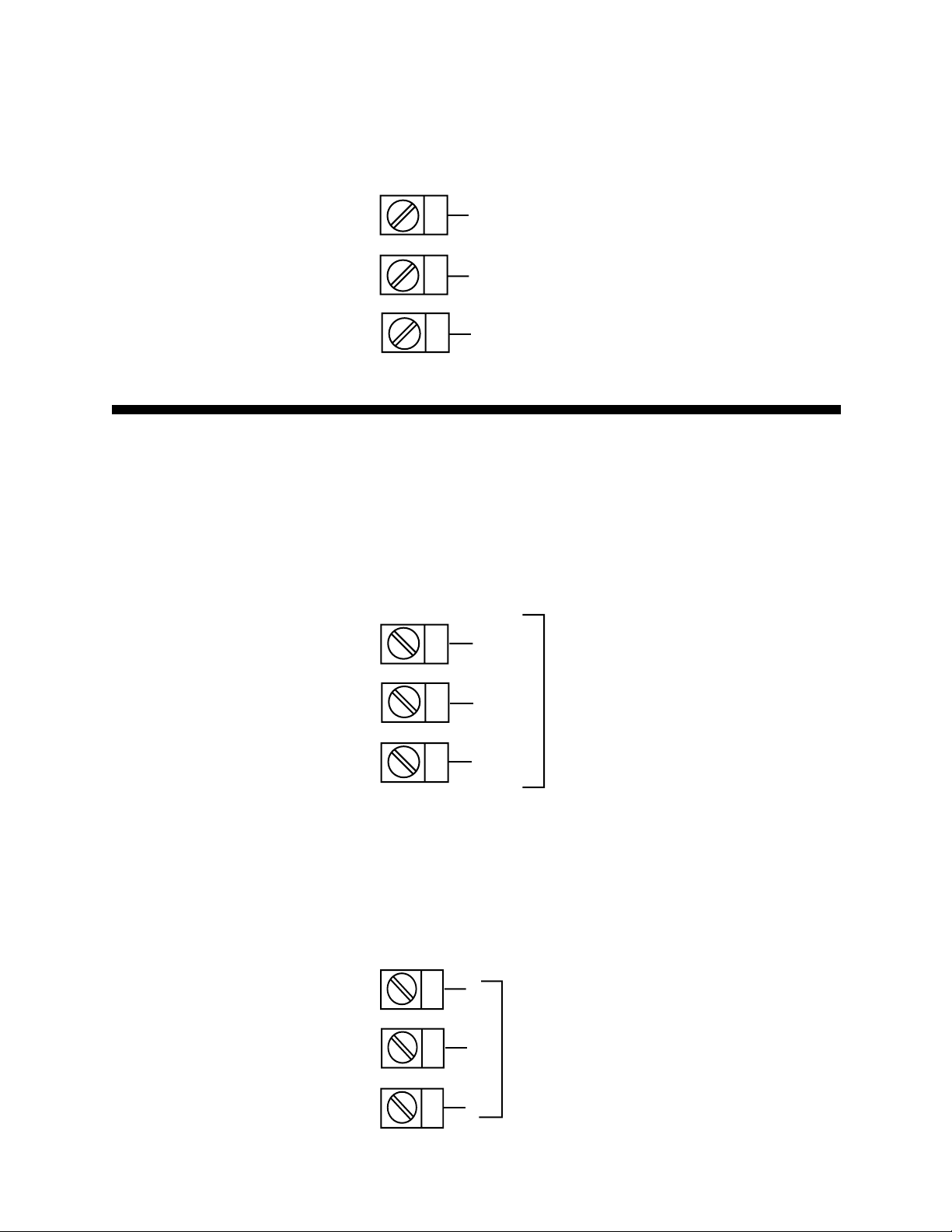
FIGURE 2-12
Remote Digital Communications - RS485
Make digital communication connections as illustrated below.
16
17
18
B
A
COM
Output Connections 2.5
FIGURE 2-13
Relay Output 1 (Control Output 1)
Connections are made to Output 1 relay as illustrated below. The contacts
are rated at 2 amp resistive, 120/240 Vac .
19
N/C
20
21
FIGURE 2-14
dc Pulse Output 1 (Control Output 1)
Connections are made to Output 1 dc Pulse as illustrated below. The solid
state relay driver is a non-isolated 0-4 Vdc nominal signal. Output impedance is 250 ohms.
19
20
21
C
Relay
N/O
-
dc Pulse
+
15
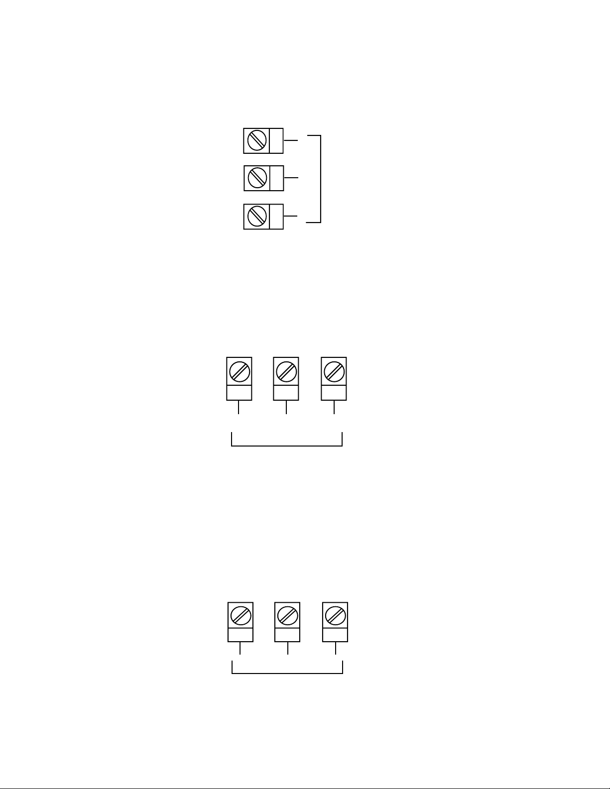
FIGURE 2-15
mAdc Output 1 (Control Output 1)
Make connections for analog dc Output 1 as illustrated below.
19
-
20
21
+
Analog dc
FIGURE 2-16
Relay Output 2 (Control Output 2 OR Alarm 2)
Connections are made to Output 2 relay as illustrated below. The contacts
are rated at 2 amp resistive, 120/240 Vac.
24 23 22
N/O
C
N/C
Relay
FIGURE 2-17
SSR Driver Output 2 (Control Output 2 OR Alarm 2)
Connections are made to Output 2 dc Pulse as illustrated below. The solid
state relay driver is a non-isolated 0-4 Vdc nominal signal. Output impedance is 250 ohms.
24 23 22
+
dc Pulse
-
16
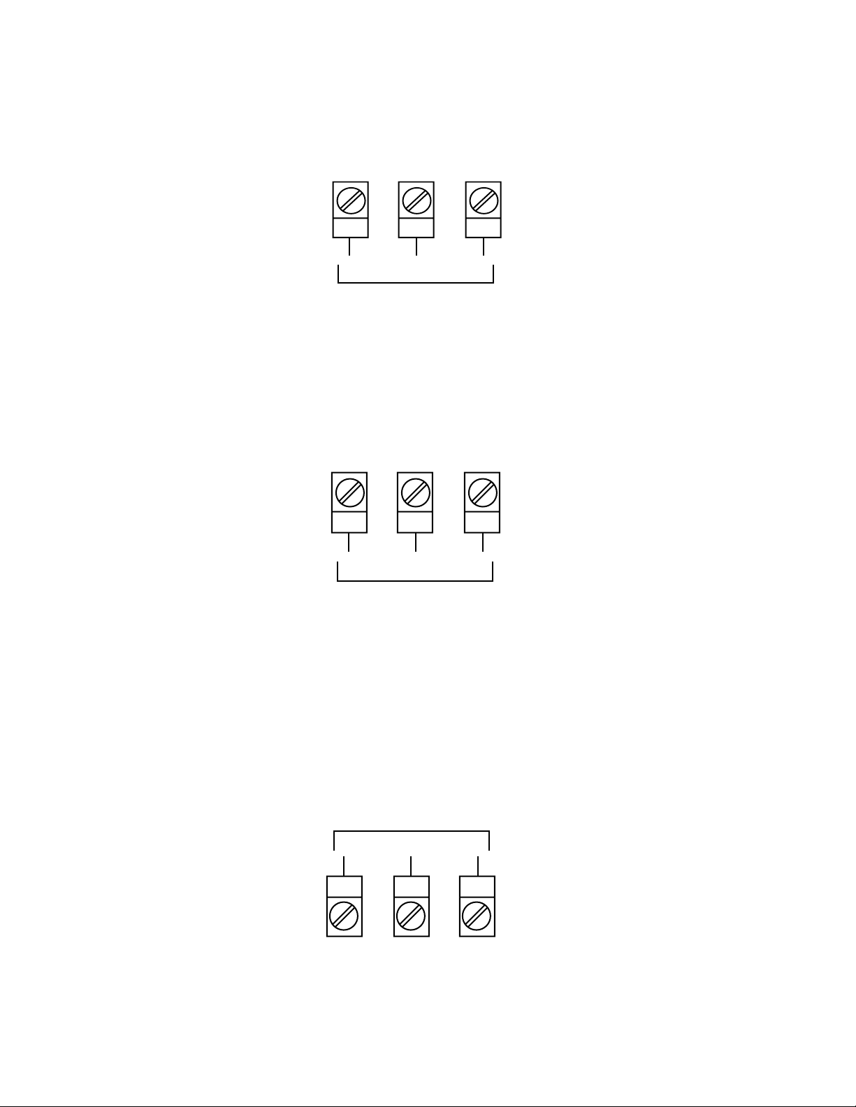
FIGURE 2-18
mAdc Output 2 (Control Output 2)
Make connections for analog dc Output 2 as illustrated below.
24 23 22
+
Analog dc
FIGURE 2-19
Transmitter Power Supply Out 2
Make connections for 24V dc transmitter power supply as illustrated below
24 23 22
+
24VDC Transmitter Power
Supply
-
-
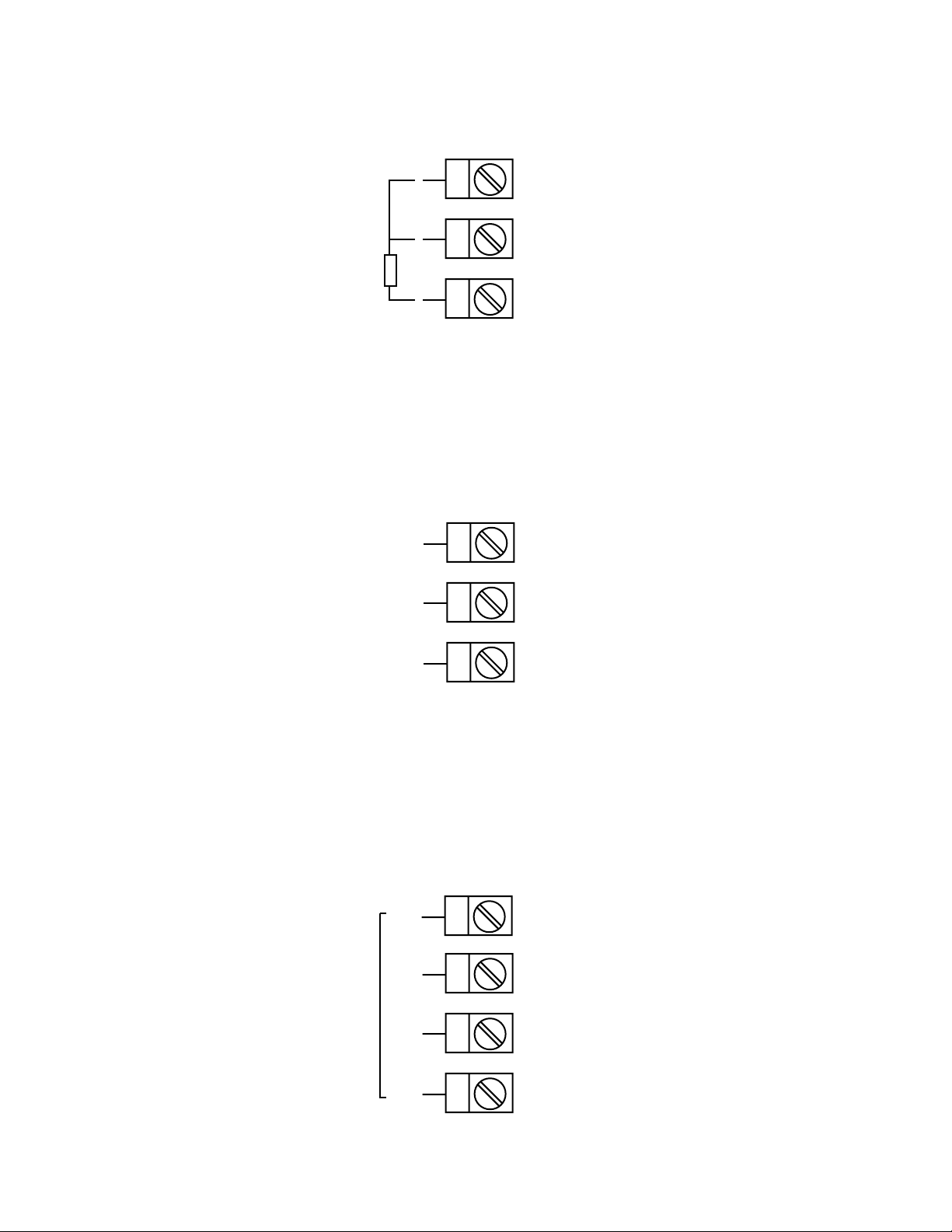
FIGURE 2-20
Relay Output 3 (Alarm 1)
Connections are made to Output 3 relay as illustrated below. The contacts
are rated at 2 amp resistive, 120/240 Vac.
Relay
N/OCN/C
10 11 12
17
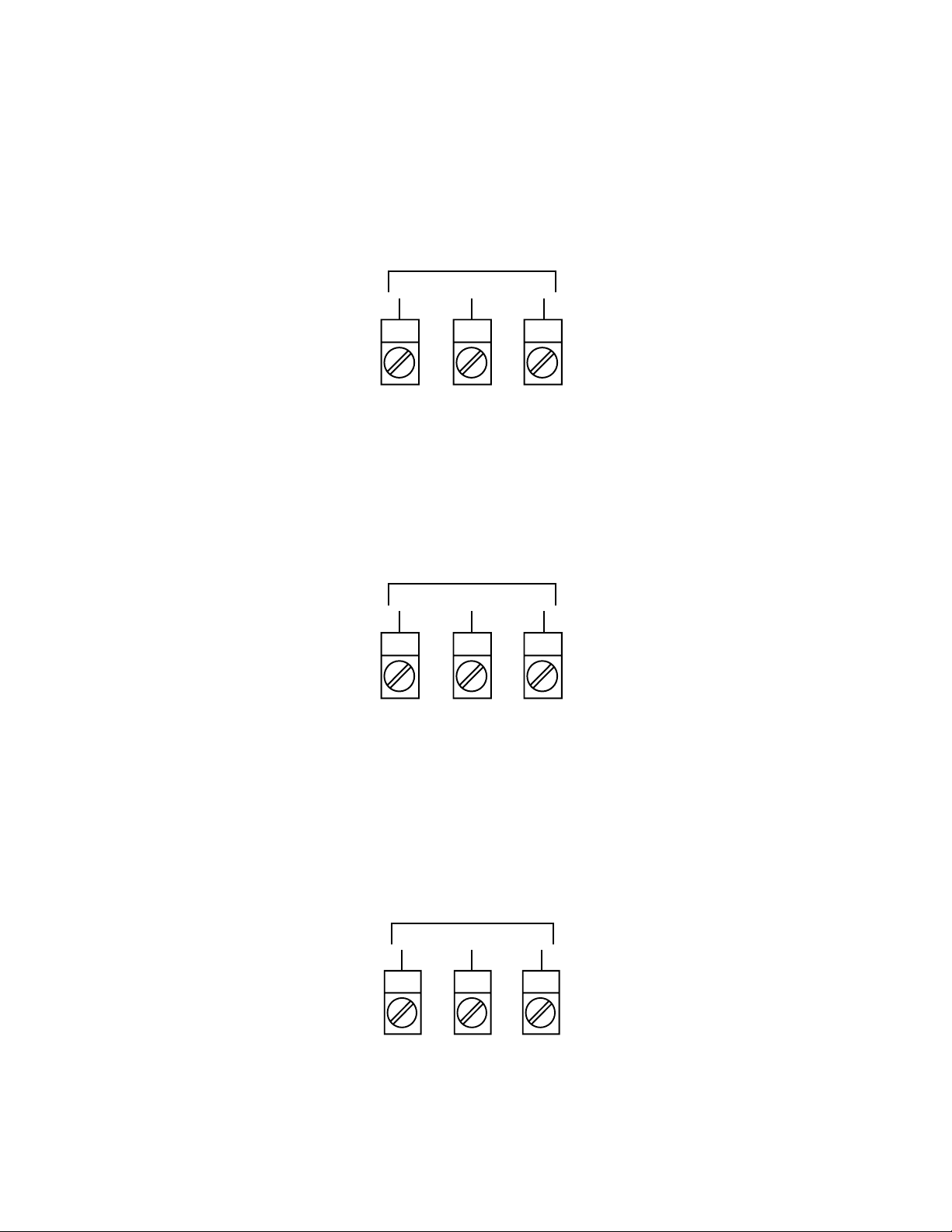
FIGURE 2-21
dc Pulse Output 3 (Alarm 1)
Connections are made to Output 3 dc Pulse as illustrated below. The solid
state relay driver is a non-isolated 0-4 Vdc nominal signal. Output impedance is 250 ohms.
dc Pulse
-
10 11 12
FIGURE 2-22
mAdc Output 3 (Recorder Output Only)
Make connections for dc output 3 as illustrated below.
Analog dc
-
10 11 12
+
+
FIGURE 2-23
Transmitter Power Supply Out 3
Make connections for 24Vdc transmitter power supply as illustrated below.
24 Vdc Transmitter
Power Supply
-
10 11 12
18
+
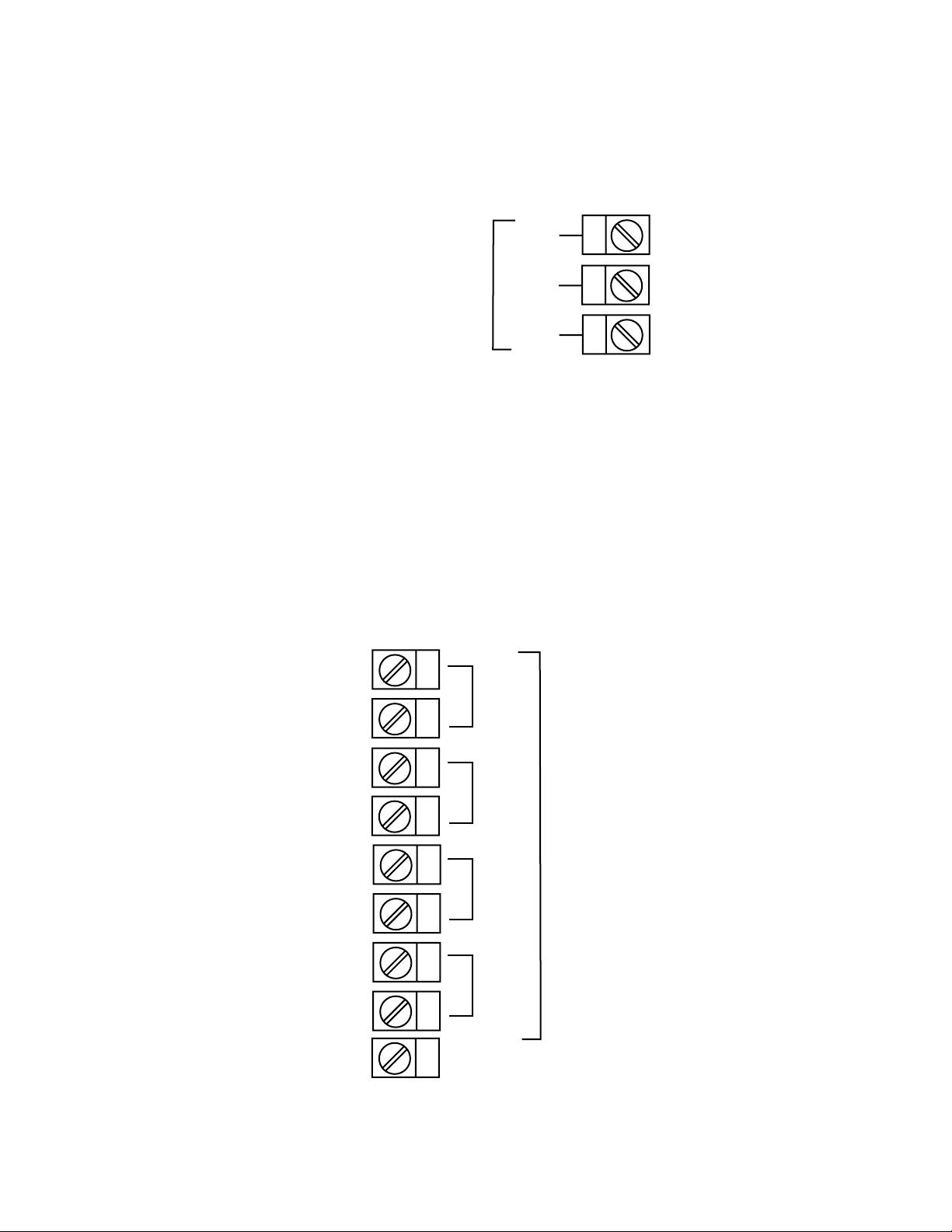
FIGURE 2-24
End of Program Output
Connections are made to End of Program Output as shown below. The
contacts are rated at 5 amp resistive, 120/240 Vac.
N/O
9
END OF
PROGRAM
C
8
OUTPUT
N/C
7
FIGURE 2-25
Event Outputs (optional)
If the Event Outputs have been specified and if the External Option parameter in Hardware Definition is set to either OUT of BOTH, Event Outputs
are available. Make connections as shown on top of next page. The contacts are rated at 5 amps, 120/240 Vac.
34
#1
35
36
37
38
39
40
41
42
#2
#3
EVENT OUTPUTS
#4
19

FIGURE 2-26
Remote Program Outputs (optional)
If the Remote Program Control Inputs has been specified, make connections as shown. These inputs can be either TTL or switch contact, selectable in Hardware Definition. The following applies:
Terminals 31 (R2) to 33 (RO) provide a binary-coded input which is used to
select the program:
Digital Inputs=TTL Level Digital Inputs=Contacts (switches)
R0 R1 R2 Progran Select R0 R1 R2 Program Select
0 0 0 Program 1 Closed Open Open Program 1
1 0 0 Program 2 Open Closed Open Program 2
0 1 0 Program 3 Closed Closed Open Program 3
1 1 0 Program 4 Open Open Closed Program 4
0 0 1 Program 5 Closed Open Closed Program 5
1 0 1 Program 6 Open Closed Closed Program 6
0 1 1 Program 7 Closed Closed Closed Program 7
1 1 1 Program 8 Open Open Open Program 8
For the Program Control Inputs, the following convention has been
adopted: for TTL inputs OFF=logic 0, ON=logic 1; for contacts (switch)
inputs OFFG=open, ON=closed.
Terminal 30 is the Program Abort control. It is EDGE SENSITIVE; an OFFON transition at any time will cause an immediate Program Abort.
Terminal 29 provides the Remote Run/Hold Program control and has an
identical effect to that of the Run/Hold key on the front panel. An OFF-ON
transition will cause the currently selected program to be run (or to be resumed if it is currently held); AN ON-OFF transition will cause the currently
running program to be held. Powering up the instrument with this terminal
ON will not cause a program to run.
Terminal 28 provides the "x60" program time base selection. This terminal
is LEVEL SENSITIVE (ON=minutes/seconds, OFF=hours/minutes). When
the instrument is powered up, the initially powered time bese will be according to the level on this terminal at power-up.
NOTE: All remote selection/control functions except the Abort function have
20
precedence over the corresponding front panel controls. The "x60" function will also take precedence over any present x60 parameter settings.
33
R0
32
R1
31
R2
RESET
RUN/HOLD
30
29
REMOTE INPUTS
C
28
27
X60 (FAST)
Note: Only one remote connection shown for clarity.
FIGURE 2-27
Valve Motor Drive (VMD) Control Relay Outputs 1 & 2
The contacts are rated at 2A resistive at 120V (motor drive). Connections
are made as shown below.
19
20
N/C
C
Relay
Output 1
24 23 22
N/O
C
Relay
Output 2
N/C
21
N/O
NOTE: With VMD control, the controller is designed to switch on either
Output 1 or Output 2 (to open or close the valve). However, under fault
conditions, both Output 1 and Output 2 relays could be switched on simultaneously. For safety purposes, an interlock can be included which connects the supply to the motor via the "normally closed" relay contacts on
the Output 1 and Output 2 relays (see Figure 2-26)
21
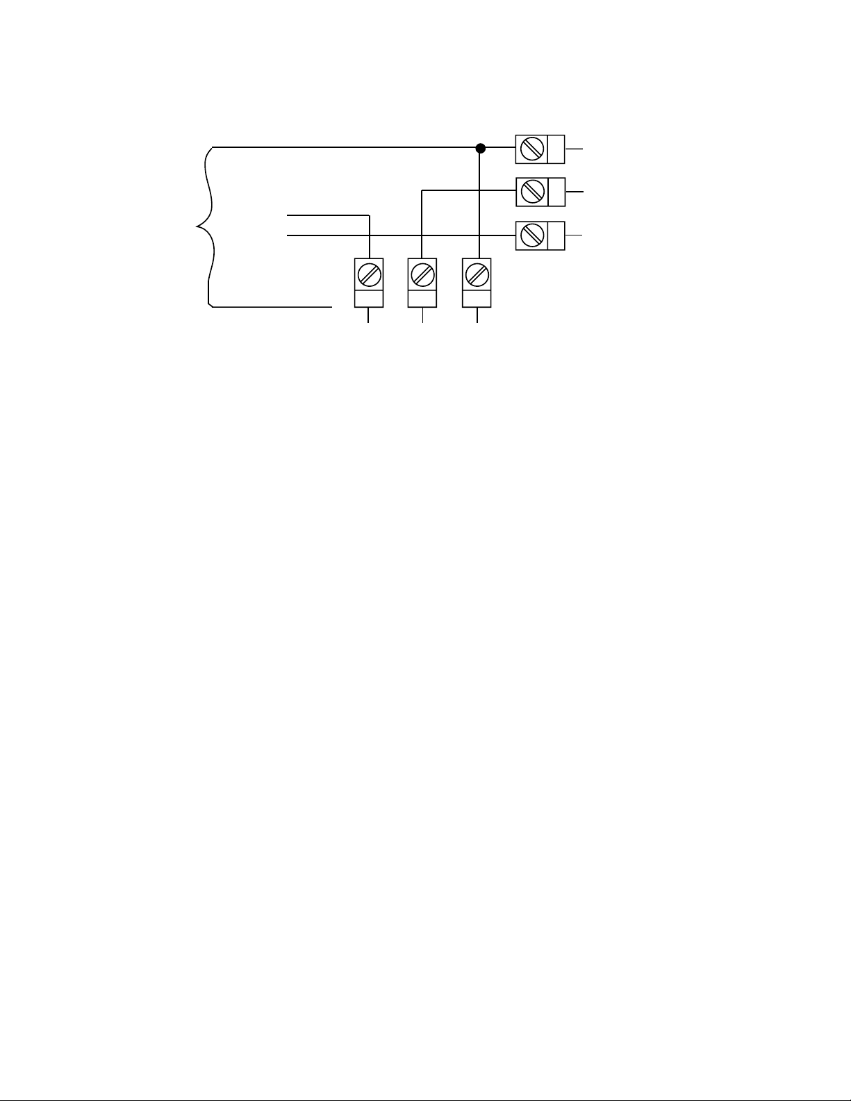
FIGURE 2-28
Motor
Supply
Close
Open
Common
24 23 22
N/O
"Close V alve" Relay
C
N/C
19
20
21
N/C
C
N/O
"Open
Valve"
Relay
22
Section 3 - Operation
3.1 POWER UP PROCEDURE
Verify all electrical connections have been properly made before applying
power to the instrument.
If the instrument is being powered for the first time, it may be desirable to
disconnect the controller output connections. The instrument will be into
control following the power up sequence and the output(s) may turn ON .
During Power up, a self-test procedure is initiated during which all LED
segments in the two front panel displays appear and all LED indicators are
ON . When the self-test procedure is complete, the instrument reverts to
normal operation.
Note: When power is first applied, a delay of approx. 3 seconds will be
seen before the displays light up.
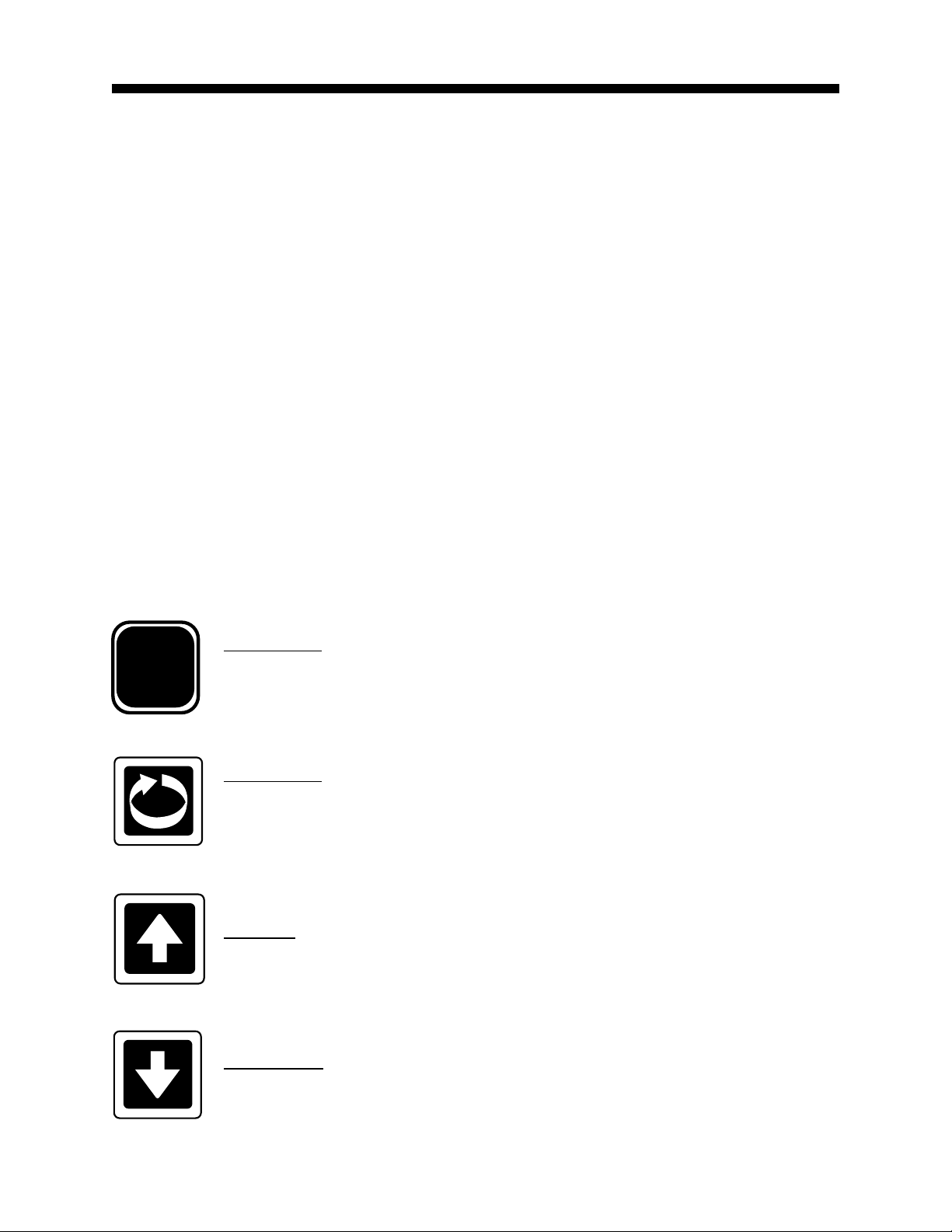
3.2 KEYPAD OPERATION
Mode Key
MODE
Cycles through modes available in the instrument.
Scroll Key
Displays the next parameter in sequence (indicated by Message display).
Up Key
Increments displayed parameter value/cycles through options.
Down Key
Decrements displayed parameter value/cycles through options.
23
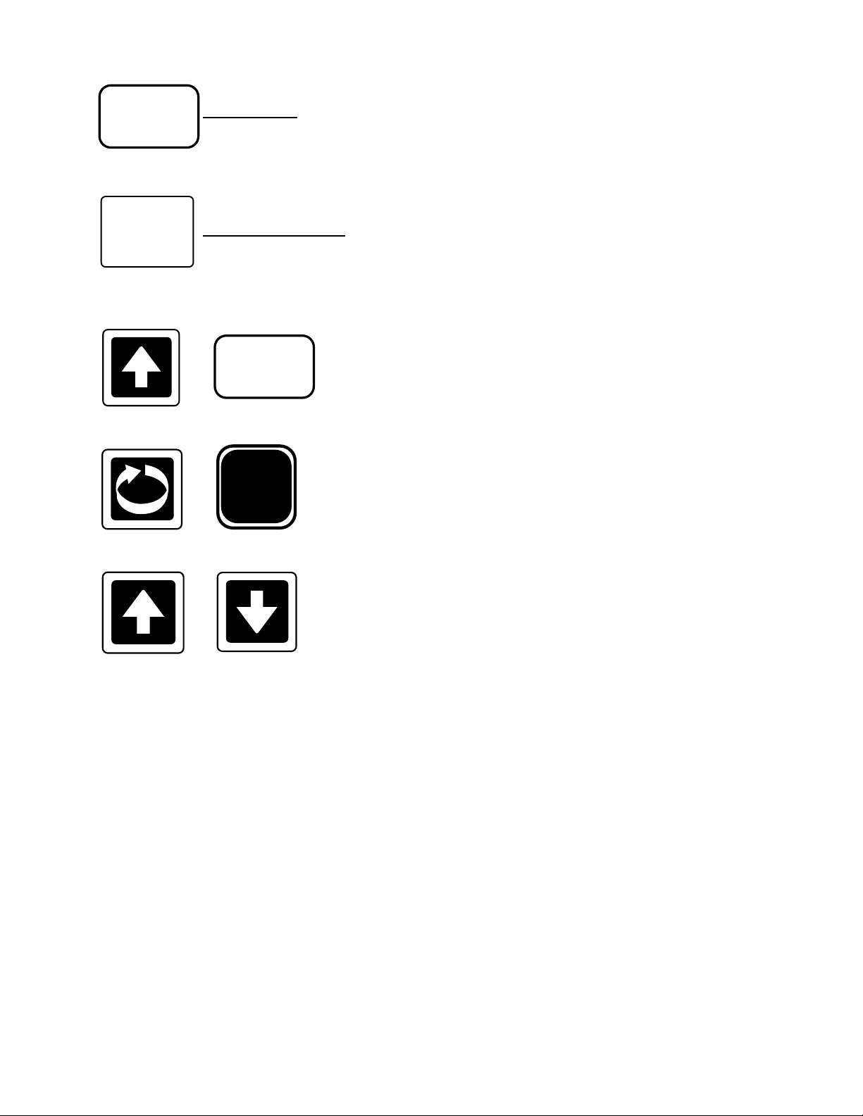
PROF
PROF Key
Cycles through Program (profile) numbers.
RUN/HOLD
RUN/HOLD Key
Runs, holds or aborts current program (profile).
+
+
+
PROF
MODE
Jumps to next segment, when program is
running.
Selects/de-selects Manual Control
Sets a segment to Dwell when defining a
program.
24
 Loading...