

Omega Products CN144-MA-DC Installation Manual

"Notice"
Please ensure that this instruction manual is given to the final user of the instrument.
Preface
This instruction manual is meant for those who will be involved in the wiring, installation, operation and routine maintenance of the CN140
series.
This manual describes the care, installation, wiring, function, and proper procedures for the operation of the CN140 series. Keep this
manual at the work site during operation of the CN140 series. While using this instrument, you should always follow the guidance provided herein.
For matters regarding safety, potential damage to equipment and/or facilities, additional instructions are indicated by the following headings:
WARNING
Exercise extreme caution as indicated. This heading indicates hazardous conditions that could cause injury or death of personnel.
CAUTION
Exercise extreme caution as indicated. This heading indicates hazardous conditions that could cause damage to equipment and/or facilities.
NOTE
This heading indicates additional instructions and/or notes.
The mark designates a protective conductor terminal. Make sure to properly ground it.
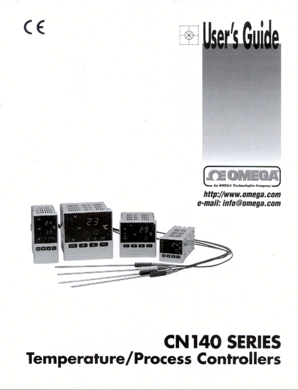
CN140 Series
Digital controller
Instruction Manual
Thank you for purchasing the Omega CN140 Series. Please check that the delivered product is the correct item you
ordered. Please do not begin operating this product until you have read this instruction manual thoroughly and
understand its contents.
- 2 -
For matters regarding safety
series controller is designed for controlling temperature, humidity
and other physical subjects. It must not be used in any way that may
adversely affect the safety, health or working conditions of those who
come into contact with the effects of its usage. When used, adequate and
effective safety countermeasures must be provided at all times. No
warranty, express or implied, is valid in the case of using this product
without the use of proper safety countermeasures correspondingly.
WARNING
To avoid damage to the connected equipment, facilities or the product
itself due to a fault of the product, safety countermeasure must be taken
before usage, such as proper installation of the fuse and the overheating
protection device. No warranty, express or implied, is valid in the case of
usage without having implemented proper safety countermeasures.
CAUTION
• The mark on the plate affixed to the instrument:
On the terminal nameplate affixed to the case of your instrument, the
mark is printed. This is to warn you of the risk of electrical shock
which may result if the charger is touched while it is energized.
• A means to allow the power to be turned off, such as a switch or a
breaker, should be installed in the external power circuit to be connected
to the power terminal of the instrument.
Fix the switch or the breaker adjacently to the instrument in a position
which allows it to be operated with ease, and with an indication that it is
a means of turning the power off. The switch or the breaker should meet
the requirements of IEC947.
• Fuse:
Since the instrument does not have a built-in fuse, do not forget to install
a fuse in the power circuit to be connected to the power terminal.
The fuse should be positioned between the switch or the breaker and the
instrument and be attached to the L side of the power terminal.
Fuse Rating: 250V AC 0.5A/medium lagged or lagged type
Use a fuse which meets the requirements of IEC127.
• Voltage/current of a load to be connected to the output
terminal and the alarm terminal should be within a rated range.
Otherwise, the temperature will rise and reduce the life of the product
and/or result in problems with the product.
For the rated voltage/current, see 7. Specifications on page 23.
The output terminal should be connected with a device which meets the
requirements of IEC1010.
• A voltage/current different from that of the input specification should
not be added on the input terminal. It may reduce the life of the product
and/or result in problems with the product.
For the rated voltage/current, see 7. Specification on page 23.
For the rated voltage (mV or V) or current (4-20mA) input, the input
terminal should be connected with a device which meets the
requirements of IEC1010 as input terminals.
• As the CT input terminal for the heater break alarm (optional), only the
attachment CT should be used. Using anything else may result in
problems with the product.
For the CT provided, refer to 1-1. Check before Use on page 11.
• The series controller is provided with a draft hole for heat
discharge. Take care to prevent metal or other foreign matter from
obstructing it. Failure to do so may result in problems with the product
and may even result in fire.
• Do not block the draft hole or allow dust or the like to adhere to it. Any
rise in temperature or insulation failure may result in a shortening of the
life of product and/or problems with the product. For spaces between
installed instruments, refer to 2-4. External Dimensions and Panel
Cutout on page 12.
• It should be noted that repeated tolerance tests against voltage, noise,
surge, etc., may lead to deterioration of the instrument.
• Remodeling the instrument or using it in an anomalous way is
prohibited.
CAUTION
Page
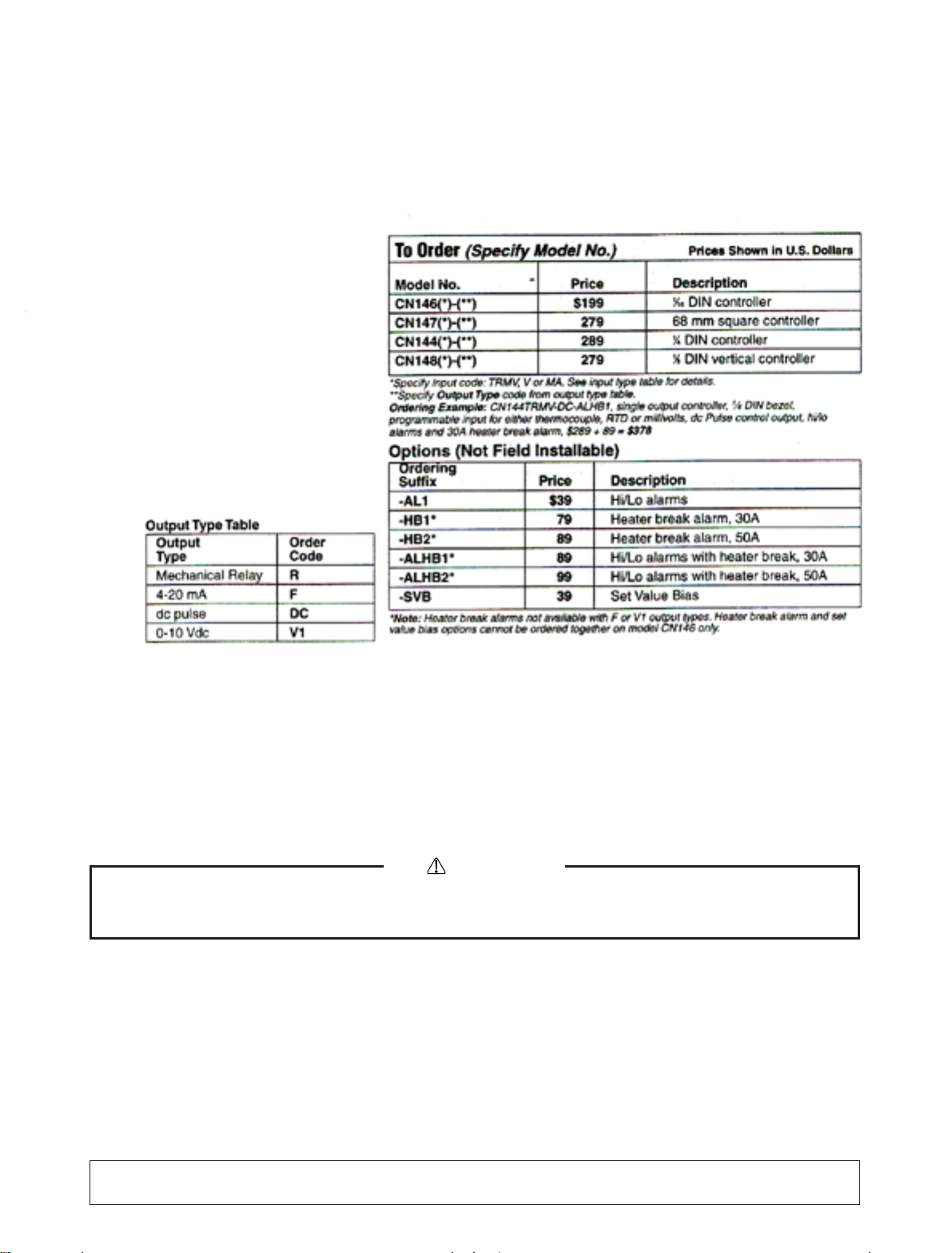
1. Introduction...................................................................................3
1-1. Check before use.....................................................................3
1-2. Caution for use........................................................................3
2. Installation and wiring.................................................................3
2-1. Installation site (environmental conditions) ...........................3
2-2. Mounting.................................................................................4
2-3. How to remove the instrument out of the case .......................4
2-4. External dimensions and panel cutout ....................................4
2-5. Wiring .....................................................................................5
2-6. Terminal arrangement.............................................................5
2-7. Terminal arrangement table ....................................................5
3. Instruction for front panel ...........................................................6
3-1. Drawing and the name of the parts .........................................6
3-2. Instruction for front panel .......................................................6
4. Screen instruction........................................................................7
4-1. Power on and initial screen display ........................................7
4-2. Screen change .........................................................................7
4-3. Screen configuration ...............................................................8
4-4. Instruction for screen change and each screen........................9
4-5. Measuring range code table ..................................................10
4-6. Alarm type code table ...........................................................10
5. Operation....................................................................................10
5-1. Setting of set value (SV).......................................................10
5-2. AT (Auto tuning) ..................................................................11
5-3. Setting of alarm.....................................................................12
6. Supplement................................................................................13
6-1. Auto return function..............................................................13
6-2. PID (Screen No.2,4 and 5 of mode 1 screen group) .............13
6-3. Control output characteristics ...............................................14
(
digit of mode 2 screen)
6-4. Error message .......................................................................14
7. Specifications.............................................................................15
Contents
1. Introduction
1-1. Check before use
This product has been fully checked for quality assurance prior to shipment. Nevertheless, you are requested to make sure that there is no error, damage or
shortage of delivered items by confirming the model codes and checking the external view of the product and the number of accessories.
1-2. Caution for use
(1) Avoid operating keys of the front panel with hard or sharp objects or motions. Lightly touch the operationg keys with finger tip
for operation.
(2) Avoid using solvents such as thinner. Wipe gently with a dry cloth.
2. Installation and wiring
2-1. Installation site (environmental conditions)
In the case where there is an intention to operate this product at one of the following sites, be aware that the occurance of fire and/
or other dangerous situations is considerable.
Exercise caution and avoid these places when selecting an operational site.
CAUTION
(1) Where flammable gas, corrosive gas, oil mist and particles that can deteriorate electrical insulation are generated or are abundant.
(2) Where the temperature is below -10˚C or above 50˚C
(3) Where the relative humidity is 90%RH or below dew point.
(4) Where highly intense vibration or impact is generated or transferred.
(5) Near high voltage power lines or where inductive interference can affect the operation of the product.
(6) Dew drops or direct exposure to sun light.
(7) Where the elevation is in excess of 2,000m.
NOTE: The environmental conditions belong to the installation category II of IEC 664 and the degree of pollution is 2.
- 3 -
2-2. Mounting
(1) Machine the mounting hole by referring to panel cutout in section 2-4.
(2) Applicable thickness of the mounting panel is from 1.0 to 3.5mm.
(3) As this product provides mounting fixture, insert the product from the front panel for installation.
2-3. How to remove the instrument out of the case
- 4 -
When the instrument is removed/replaced in the case, make sure the power is off. If it is done while the power is on, it may lead to
problems with the product and/or other problems.
CAUTION
There is no need to remove your controller out of
the case. Nevertheless, should the need arise, for example,
for replacement, follow the steps described below:
Insert a minius screwdriver of 6mm
~9mm into the opening
(where packing is exposed) of the front case and rotate the
screwdriver while pushing up the lock lever behind the
packing. Once the instrument comes out by a few
millimeters, you can remove it by hand.
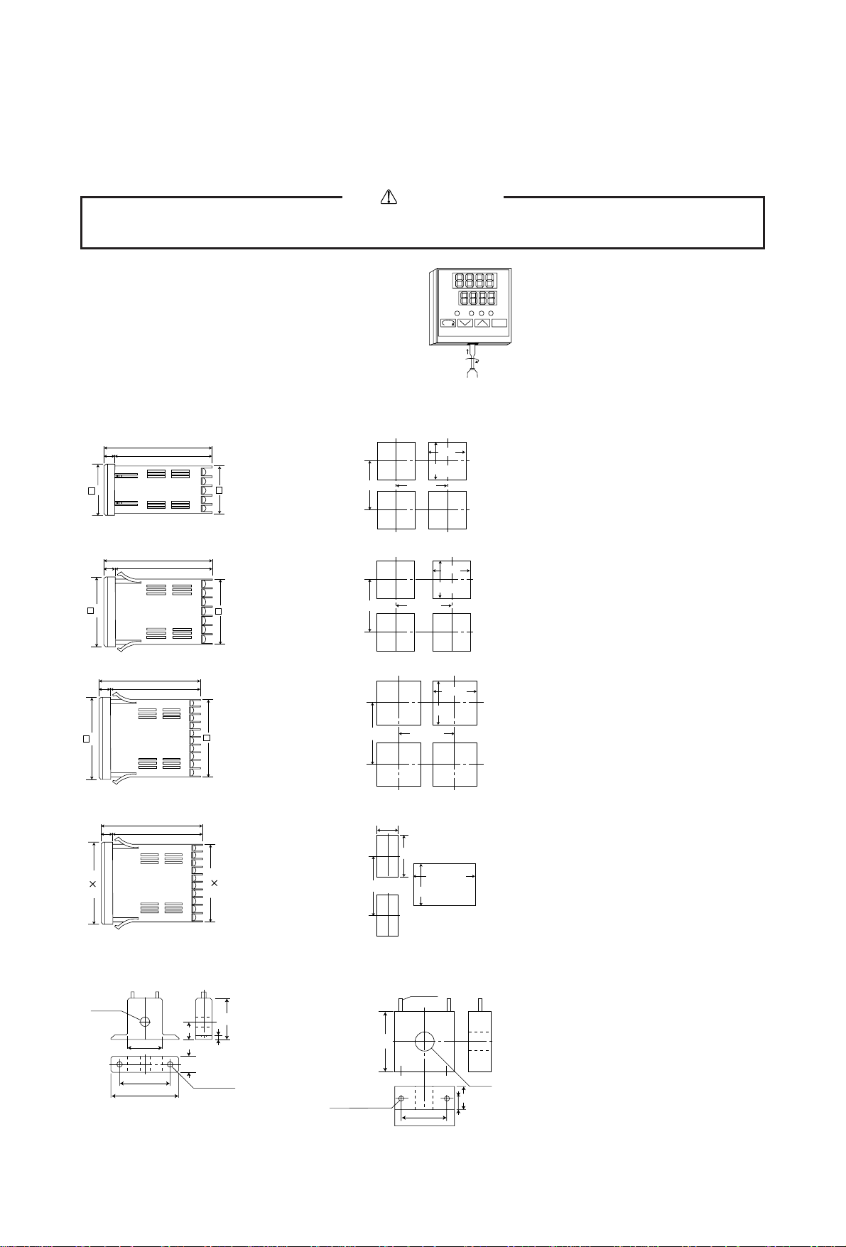
2-4. External dimensions and panel cutout
CN146 External dimensions (unit: mm)
CN147 External dimensions (unit: mm)
CN144 External dimensions (unit: mm)
CN148 External dimensions (unit: mm)
Dimension of current transformer (CT) for heater break alarm
30A (CTL-6-S) (unit: mm)
CN146 Panel cutout (unit: mm)
CN147 Panel cutout (unit: mm)
CN144 Panel cutout (unit: mm)
CN148 Panel cutout (unit: mm)
50A (CTL-12-S36-8) (unit: mm)
48
44.7
110
100
10
longer than 60
longer than
60
longer than
100
45
72
67.6
110
100
10
96
91.6
110
100
10
longer than 100
68
92
+
0.8
0
96
48
91.6
44.6
110
100
10
45
+
0.6
0
92
+
0.8
0
+
1
0
92
+
0.8
0
(48 × N-3)
ø 5.8
25
3
10.5
21
30
40
10
2— ø 3.5
40
ø 2.36
ø 12
2-M3 depth4
30
40
15
7.5
longer than
130
longer than 130
longer than 130
When N pieces are installed laterally
N=number
45
+
0.6
0
+
0.6
0
68
+
0.7
0
+
0.7
0
92
+
0.8
0
ENT
PV
SV
˚C
•••
•• •• •••••
••••••••••••••••••••
 Loading...