


Omega Products CN1166 Installation Manual
1
-DIN
16
RAMP/SOAK PROFILE
CONTROLLER
Product Manual
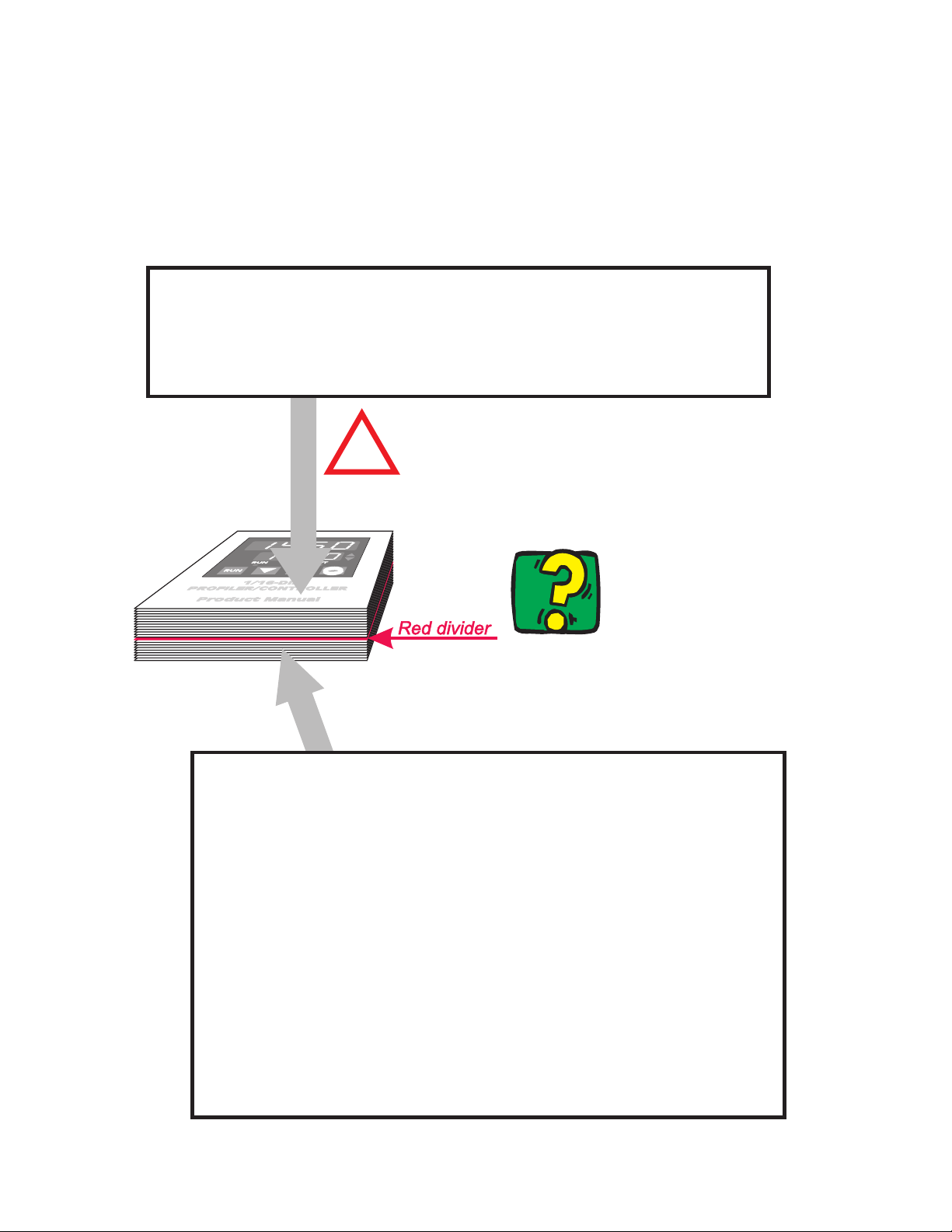
HOW TO USE THIS MANUAL
This manual comprises two volumes:
VOLUME I
INST ALLA T ION & CONF IGURA T ION INST RUC T IONS
SECTION 1 Panel-mounting and wiring-up the Profile Controller
SECTION 2 Selecting the required input/output type(s)
SECTION 3 Matching software to hardware fitted
Selecting input range, control action, alarm type(s)
and Program Mode
!
The functions described in Volum e Imust
be perform ed only by personnel who are
trained, equipped and authorised to do so.
To find a specific
topic, refer to the index
at the rear of this manual
VOLUME II
OPERATINGINSTRUCTIONS
SECTION 1 Monitoring the process and adjusting the setpoint
Starting/holding/releasing/aborting a program
Monitoring a running/held program
Manual Control
SECTION 2 Setting up the controller parameters
SECTION 3 Creating/editing a program
Using Guaranteed Soak Band
Segment Event Status
SECTION 4 Setting up and using the communications
link between the Profile Controller and your
computer
APPENDIX A Product specification
APPENDIX B Summary of front panel displays

1
-DIN RAMP/SOAK PROFILE CONTROLLER
16
PRODUCT MANUAL
VOLUME I
INSTALLATION & CONFIGURATION
INSTRUCTIONS
The procedures described in this Volume must be undertaken only by
technically-competent servicing personnel.
CONTENTS
1 INSTALLATION 1-1
1.1 UNPACKING PROCEDURE 1-1
1.2 PANEL-MOUNTING THE CONTROLLER 1-1
1.3 CONNECTIONS AND WIRING 1-2
2 INTERNAL LINKS AND SWITCHES 2-1
2.1 REMOVING THE PROFILE CONTROLLER FROM ITS HOUSING 2-1
2.2 REMOVING/REPLACING THE OUTPUT 2/OUTPUT 3 OPTION PCBs 2-3
2.3 REMOVING/REPLACING THE RS485 COMMUNICATIONS
OPTION PCB OR REMOTE RUN/HOLD OPTION PCB 2-3
2.4 REPLACING THE INSTRUMENT IN ITS HOUSING 2-3
2.5 SELECTION OF INPUT TYPE AND OUTPUT 1 TYPE 2-4
2.6 OUTPUT 2 TYPE/OUTPUT 3 TYPE 2-6
3 CONFIGURATION MODE 3-1
3.1 ENTRY INTO CONFIGURATION MODE 3-1
3.2 HARDWARE DEFINITION CODE 3-1
3.3 OPTION SELECTION 3-3
3.4 CONFIGURATION MODE PARAMETERS 3-4
3.5 EXIT FROM CONFIGURATION MODE 3-9
PM077-V1 Volume I (i)
1 INSTALLATION
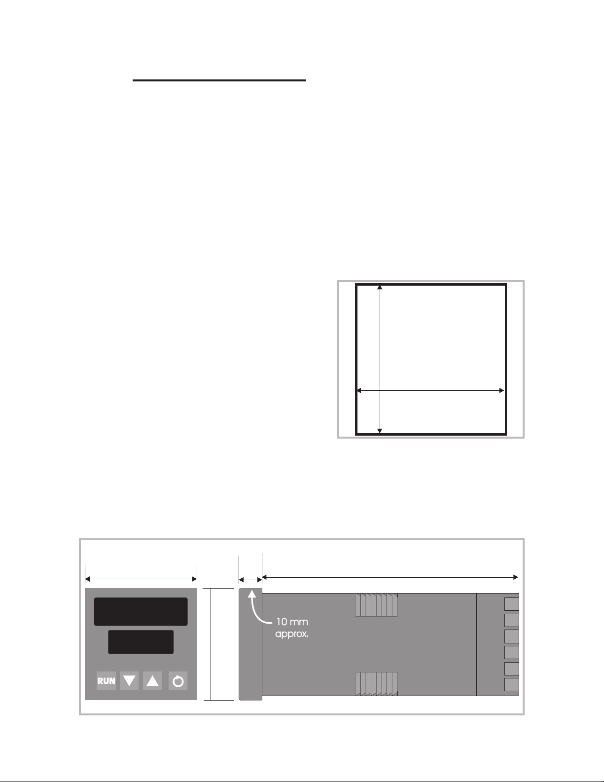
1.1
1.2
The panel on which the Profile Controller is to
be mounted must be rigid and may be up to
6.0mm (0.25 inches) thick. The cut-out required
for a single Profile Controller is as shown in
Figure 1-1.
Several instruments may be installed in a single
cut-out, side-by-side. For n Profile Controllers
mounted side-by-side, the width of the cut-out
would be:
UNPACKING PROCEDURE
1. Remove the Profile Controller from its packing. The Controller is
supplied with a panel gasket and push-fit fixing strap. Retain the
packing for future use, should it be necessary to transport the Profile
Controller to a different site or to return it to the supplier for
repair/testing.
2. Examine the delivered items for damage or deficiencies. If any is
found, notify the carrier immediately.
PANEL-MOUNTING THE CONTROLLER
45m m +0.5 -0.0
45m m +0.5 -0.0
(48n - 4) millimetres or (3.78n - 0.16) inches.
The Profile Controller is 110mm deep (measured from the rear face of the front
panel). The front panel is 48mm high and 48mm wide. When panel-mounted, the
front panel projects 10mm from the mounting panel. The main dimensions of the
Profile Controller are shown in Figure 1-2.
48m m
48m m
Figure 1-2 Main Dimensions
Figure 1-1
110m m
S077-1 Volume I 1-1
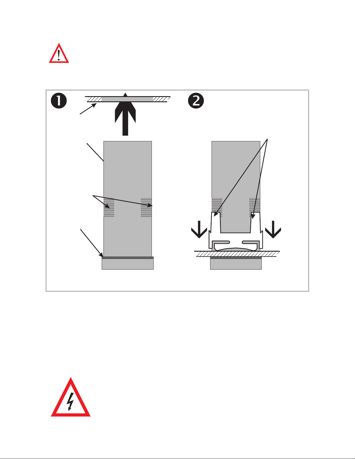
The procedure to panel-mount the Profile Controller is shown in Figure 1-3.
r
CAUTION: Do not remove the panel gasket, as this may result in
inadequate clamping of the instrument in the panel.
NOTE: When installing several instruments side-by-side in one
cut-out, use the ratchets on the top/bottom faces.
Slid e m o u n ting c lam p ove
Profile Controlle r housing towa rd s
rear face of mounting panel
Mounting panel
Profile
until tongues engage in ratchets
a n d Profile Co ntrolle r is c lam pe d
firm ly in p o sition.
Controlle r
Ho u sin g
Ratc hets
Gasket
Hold Profile Controlle r firm ly in p osition
(apply pressure to bezelonly)
Figure 1-3 Panel-Mounting the Profile Controller
Once the Profile Controller is installed in its mounting panel, it may be
subsequently removed from its housing, if necessary, as described in Subsection
2.1.
1.3
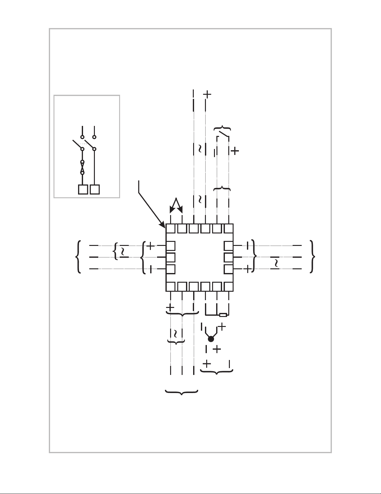
CONNECTIONS AND WIRING
The rear terminal connections are illustrated in Figure 1-4.
This instrument is designed for installation in an enclosure
which provides adequate protection against electric shock.
All pertinent local regulations should be rigidly observed.
Consideration should be given to prevention of access to the
rear terminals by unauthorised personnel.
1-2 Volume I S077-1
POWER
OU
U
INPUT
24VDC *
REMOTE
Lor -
Nor +
*Option
RUN/HOLD
24V
50/60Hz *
POWER C ONNECTION
RECOMMENDED MODE OF
9
10
N/O
C
Re la y
OUT PUT 3
N/C
appropr iate) for fuse ratings.
See Subsection 1.3.1 or 1.3.2 (as
Solid State
Top of Controller
No external connections
to be made to these
terminals.
7
8
DC/SSR Dr iv e
16 17 18
1
2
96 - 264V
L
9
3
SERIAL
COMMS.
50/60Hz
N
A
10
11
4
5
B
12
13 14 15
6
Output 1 is always the primary control
(HEAT) o u tp u t - re la y, SSR d riv e , solid
state or DC.
Re la y
T2
TP
N/C
C
DC/SSR Dr iv e
Solid State
N/O
RS485
RTD
DC/SSR Dr iv e
Th e rm o c o u p l e
Solid State
UNIVERSAL
C
N/O
Output3isusedeitherasalarm output
(relay, SSR drive or solid state) or
Output2isusedasSecondary
Con tro l (C OOL) outp u t (re la y, SSR
d riv e , solid st a te o r DC), a la rm out p ut,
EventoutputorProgram Activeoutput
(relay, SSR drive or solid state)
recorder output (DC only for SP orPV)
Re la y
OUT PUT 1
N/C
INPUT
Linear (V/m V)
Linear (m A)
Figure 1-4 Rear Terminal Connections
S077-1 Volume I 1-3

1.3.1 Mains (Line) Input
The Profile Controller will operate on 96 - 264V AC 50/60Hz mains (line) supply.
The power consumption is approximately 4 VA. Power should be connected via a
two-pole isolating switch (preferably situated near the equipment) and a 1A fuse.
If the Profile Controller has relay outputs in which the contacts are to carry mains
(line) voltage, it is recommended that the relay contact mains (line) supply should
be switched and fused in a similar manner but should be separate from the Profile
Controller mains (line) supply.
1.3.2 24V (Nominal) AC/DC Supply
The supply connections for the 24V AC/DC option of the Profile Controller are as
shown in Figure 1-4. Power should be connected via a two-pole isolating switch
and a 315mA slow-blow (anti-surge Type T) fuse.
With the 24V AC/DC supply option fitted, these terminals will accept the following
supply voltage ranges:
24V (nominal) AC 50/60Hz - 20 - 50V
24V (nominal) DC - 22 - 65V
1.3.3 Thermocouple Input
The correct type of thermocouple extension leadwire or compensating cable must
be used for the entire distance between the Profile Controller and the
thermocouple, ensuring that the correct polarity is observed throughout. Joints in
the cable should be avoided, if possible. The CJC facility must be enabled (normal
conditions) for this input (see Subsection 3.4).
NOTE: Do not run thermocouple cables adjacent to power-carrying
conductors. If the wiring is run in a conduit, use a separate conduit for the
thermocouple wiring. If the thermocouple is grounded, this must be done
at one point only. If the thermocouple extension lead is shielded, the shield
must be grounded at one point only.
1.3.4 RTD Inputs
The compensating lead should be connected to Terminal 4. For two-wire RTD
inputs, Terminals 4 and 5 should be linked. The extension leads should be of
copper and the resistance of the wires connecting the resistance element should
not exceed 5 ohms per lead (the leads should be of equal resistance).
1-4 Volume I S077-1

1.3.5 Linear Inputs
For linear mA input ranges, connection is made to Terminals 4 and 6 in the
polarity shown in Figure 1-4. For linear mV and V ranges, connection is made to
Terminals 4 and 5 in the polarity shown in Figure 1-4. For details of the linear
input ranges available, refer to Appendix A.
1.3.6 Remote Run/Hold Input
With this option fitted, Terminals 11 and 12 are used for external Run/Hold
control of the currently-selected program; this has an effect identical to that of the
front panel RUN key. These terminals may be connected to (a) the voltage-free
contacts of a switch or relay, or (b) a TTL-compatible voltage. This is an
edge-sensitive input for which the following convention has been adopted:
For TTL input, OFF = logic 1 and ON = logic 0
For a voltage-free input, OFF = open and ON = closed
Program control is as follows:
OFF-ON transition: The currently-selected program will run (or
will resume running if it is currently held).
ON-OFF transition: The currently-running program will be
held.
NOTE: When this input is used, the front panel RUN key can be
used only to abort a program. Powering-up the Profile Controller
whilst this input is ON will not cause a program to run. The RS485
Serial Communications option and the Remote Run/Hold option are
mutually exclusive.
1.3.7 Relay Outputs
The contacts are rated at 2A resistive at 120/240V AC.
1.3.8 SSR Drive Outputs
These outputs produce a time-proportioned non-isolated DC signal (0 - 4.2V
nominal into 1k
W minimum).
1.3.9 Solid State Outputs
These outputs provide up to 1A AC drive with a longer lifetime than an
electromechanical relay. For further details, refer to Appendix A.
S077-1 Volume I 1-5

1.3.10 DC Outputs
See Appendix A.
1.3.11 RS485 Serial Communications Link
The cable used should be suitable for data transfer at the selected rate (1200,
2400, 4800 or 9600 Baud) over the required distance. Transmitters/receivers
conform to the recommendations in the EIA Standard RS485.
The “A” terminal (Terminal 11) on the Profile Controller should be connected to
the “A” terminal on the master device; the “B” terminal (Terminal 12) on the
Profile Controller should be connected to the “B” terminal on the master device.
Where several Profile Controllers are connected to one master port, the master
port transceiver in the active state should be capable of driving a load of 12k
Profile Controller; the master port transceiver in the passive state must have
pull-up/pull-down resistors of sufficiently low impedance to ensure that it remains
in the quiescent state whilst supplying up to ±100
mA each to the Profile Controller
transceivers in the high impedance state.
NOTE: The RS485 Serial Communications option and the Remote
Run/Hold option are mutually exclusive.
W per
1-6 Volume I S077-1
2 INTERNAL LINKS AND SWITCHES
C
2.1 REMOVING THE PROFILE CONTROLLER FROM ITS
HOUSING
CAUTION: Before removing the instrument from its housing, ensure
that all power has been removed from the rear terminals.
To withdraw the instrument from its housing, simply grip the side edges of the
front panel (there is a finger grip on each edge) and pull the instrument forwards.
This will release the instrument from its rear connectors in the housing and will
give access to the instrument PCBs. Take note of the orientation of the instrument
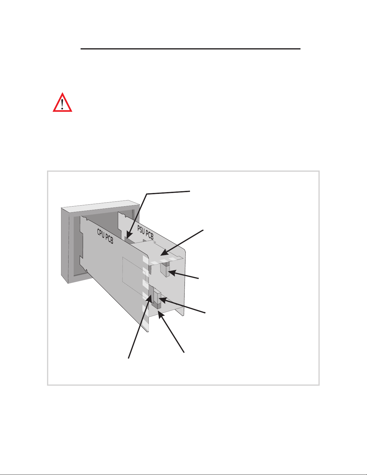
for subsequent replacement into the housing.The positions of the PCBs in the
instrument are shown in Figure 2-1.
RS485CommunicationsOption P
or
Front Panel (top edge)
Remote Run/Hold Option PCB
DC Output 1 PCB (if fitted)
Figure 2-1 PCB Positions
Out p ut 3 Op t io n PCB
(Relay, SSR Drive,
Solid State or DC Output)
Output 3 Link Jumpers
(DC Output onl y)
Output 2 Link Jumpers
(DC Output onl y)
Out p ut 2 Op t io n PCB
(Relay, SSR Drive,
Solid State or DC Output)
S077-2 Volume I 2-1
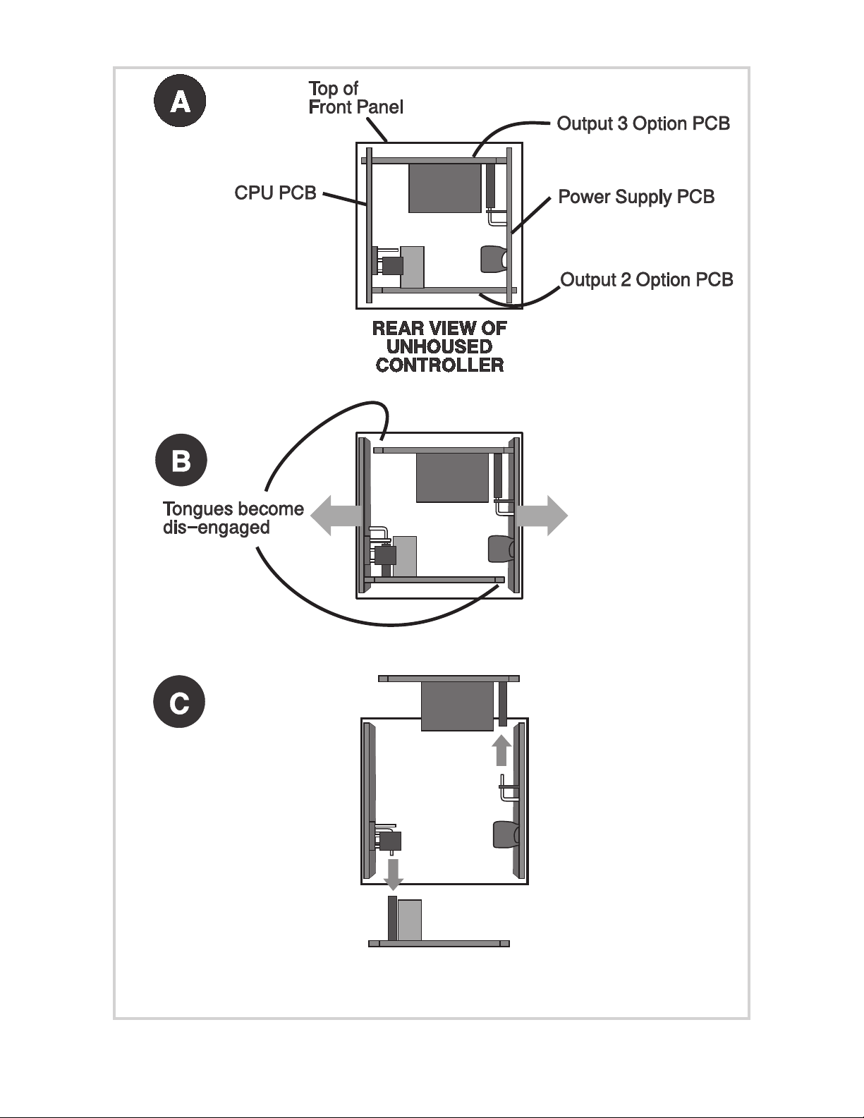
Figure 2-2 Removing the Output 2/Output 3 Option PCBs
2-2 Volume I S077-2

2.2 REMOVING/REPLACING THE OUTPUT 2/OUTPUT 3 OPTION
PCBs
With the instrument removed from its housing:
1. Gently push the rear ends of the CPU PCB and Power Supply PCB apart
slightly, until the two tongues on each of the Output 2/Output 3 Option
PCBs become disengaged - see Figure 2-2B; The Output 2 Option PCB
tongues engage in holes in the Power Supply PCB and the Output 3 Option
PCB tongues engage in holes on the CPU PCB.
2. Carefully pull the required Option PCB (Output 2 or Output 3) from its
connector (Output 2 Option PCB is connected to the CPU PCB and Output
3 Option PCB is connected to the Power Supply PCB) - see Figure 2-2C.
Note the orientation of the PCB in preparation for its replacement.
Adjustments may now be made to the link jumpers on the CPU PCB, the Output
2/Output 3 Option PCBs (if DC output) and (if fitted) the DC Output 1 PCB. The
replacement procedure is a simple reversal of the removal procedure.
2.3 REMOVING/REPLACING THE RS485 COMMUNICATIONS
OPTION PCB OR REMOTE RUN/HOLD OPTION PCB
The RS485 Communications Option PCB or Remote Run/Hold Option PCB is
mounted on the inner surface of the Power Supply PCB and can be removed when
the instrument is removed from its housing (see Subsection 2.1) Figure 2-3
illustrates the removal/replacement procedure. It is not necessary to remove the
Output 2/Output 3 Option PCBs to perform this procedure.
2.4 REPLACING THE INSTRUMENT IN ITS HOUSING
To replace the instrument, simply align the CPU PCB and Power Supply PCB with
their guides and connectors in the housing and slowly but firmly push the
instrument into position.
CAUTION: Ensure that the instrument is correctly orientated. A stop
will operate if an attempt is made to insert the instrument in the
wrong orientation (e.g. upside-down). This stop must not be
overridden.
S077-2 Volume I 2-3
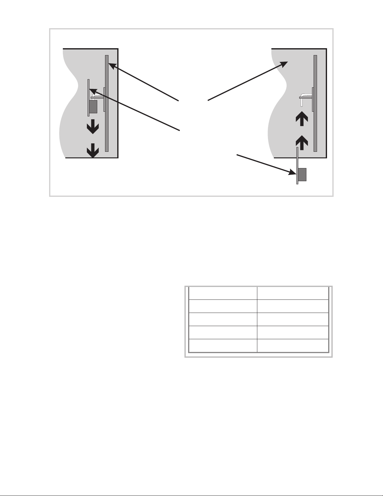
REMOVAL REPLACEMENT
View of Controller from the rear.
For clarity, the Output 2 and Output 3
Option PCBs are not shown.
PSUPCB
RS485 Serial Comms. Option PCB
or
Remote Run/Hold Option PCB
Figure 2-3 Removing the RS485 Communications Option PCB
or the Remote Run/Hold Option PCB
2.5 SELECTION OF INPUT TYPE AND OUTPUT 1 TYPE
The selection of input type and Output 1 type is accomplished on link jumpers on
the CPU PCB. The CPU PCB may be either of two forms: (a) for a relay, solid state
or SSR drive Output 1 (see Figure 2-4) or for a DC Output 1 (see Figure 2-5).
2.5.1 Input Type
The required input type is selected on
link jumpers LJ1/LJ2/LJ3 on the CPU
PCB (see Figure 2-4 or 2-5, as
appropriate, and Table 2-1).
Table 2-1 Selection of Input Type
Input Type Link Jumpers Fitted
RTD or DC (mV) None (Parked)
Thermocouple LJ3
DC (mA) LJ2
DC (V) LJ1
2-4 Volume I S077-2
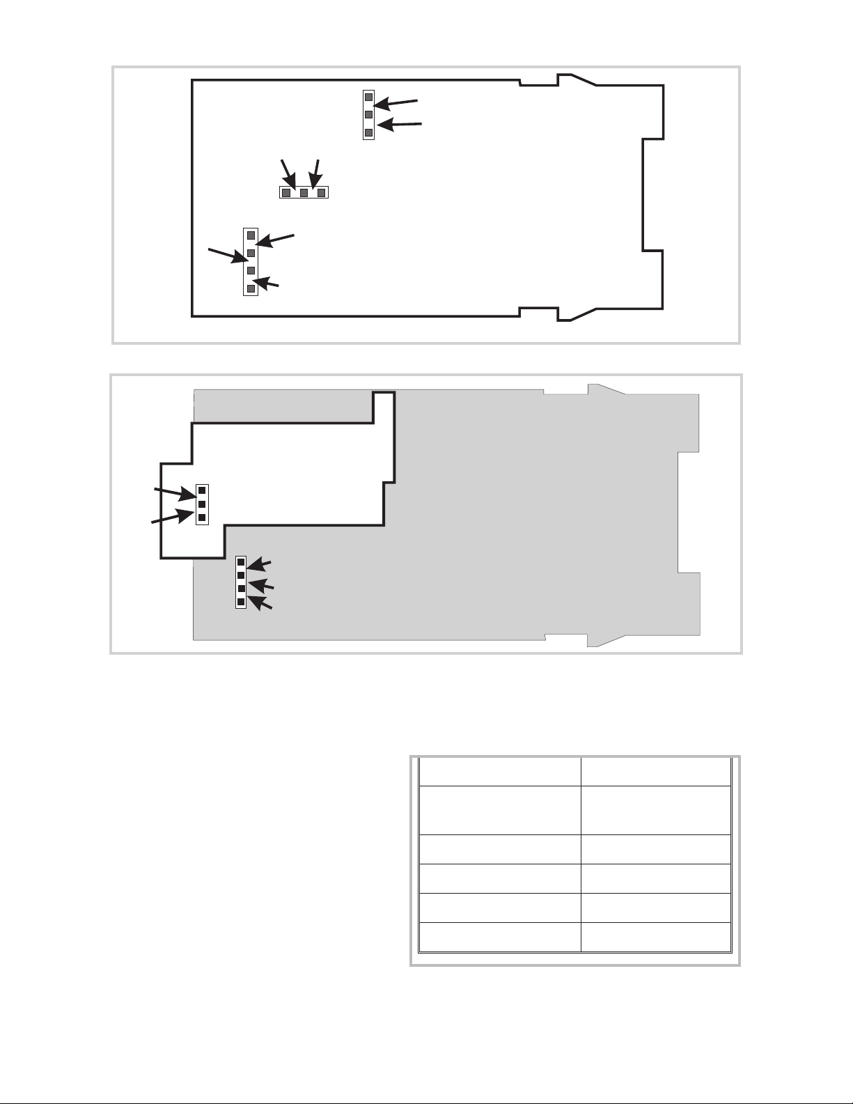
LJ6
LJ4
LJ5
LJ7
LJ8
LJ9
LJ2
LJ1
LJ3
Figure 2-4 CPU PCB (Relay/SSR Drive/Solid State Output 1)
LJ1
LJ2
LJ3
Figure 2-5 CPU PCB (DC Output 1)
2.5.2 Primary Output (Output 1) Type
The required type of Output 1 is
selected by Link Jumpers LJ4, LJ5,
LJ6 and LJ7 on the Relay/SSR
Drive/Solid State Output 1 CPU PCB
(see Figure 2-4 and Table 2-2) or, on
the DC Output 1 CPU PCB, Link
Jumpers LJ8 and LJ9 (see Figure 2-5
and Table 2-2).
Table 2-2 Selection of Output 1 Type
Relay or Solid
DC (0 - 10V) LJ8
DC (0 - 20mA) LJ9
Output 1 Type Link Jumpers Fitted
LJ5 & LJ6
State
SSR Drive LJ4 & LJ7
DC (0 - 5V) LJ8
S077-2 Volume I 2-5
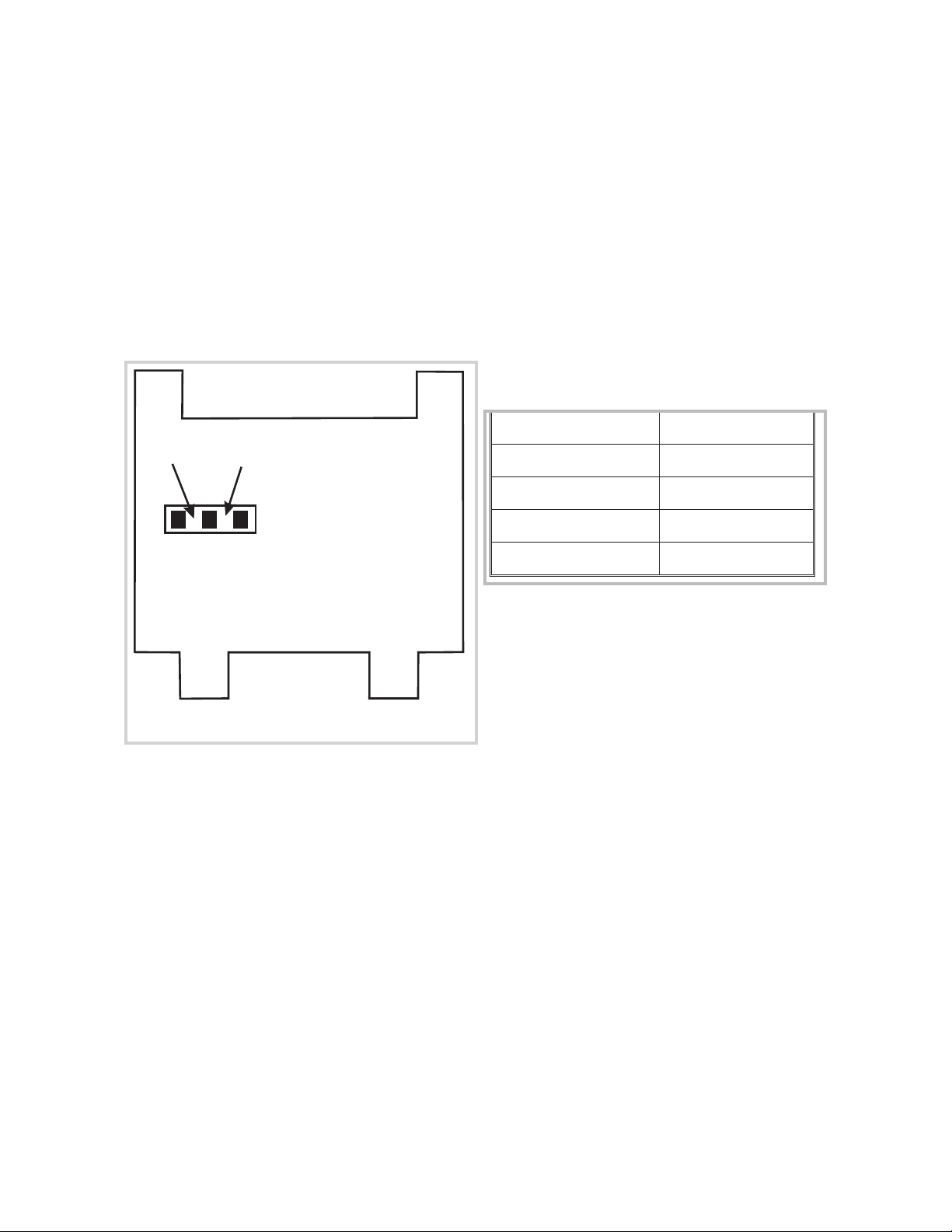
2.6 OUTPUT 2 TYPE/OUTPUT 3 TYPE
The type of output for Output 2 and Output 3 is determined by the Option PCB
fitted in the appropriate position (see Figure 2-1) and, in the case of the DC
Output Option PCB being fitted, the setting of Link Jumpers LJ8 and LJ9 on that
Option PCB (see Figure 2-6 and Table 2-3). There are three types of option PCB
which may be used for Output 2 and Output 3:
1. Relay Output Option PCB (no link jumpers)
2. Solid State Output Option PCB (no link jumpers)
3. SSR Drive Output Option PCB (no link jumpers)
3. DC Output Option PCB (link jumpers as shown in Figure 2-6)
Table 2-3 Selection of Output 2 &
Output 3 Type
DC Output Range Link Jumpers Fitted
LJ9 LJ8
DC (0 - 10V) LJ8
DC (0 - 20mA) LJ9
DC (0 - 5V) LJ8
Figure 2-6 DC Output Option PCB
(Output 2/Output 3)
DC (4 - 20mA) LJ9
2-6 Volume I S077-2
3 CONFIGURATION MODE
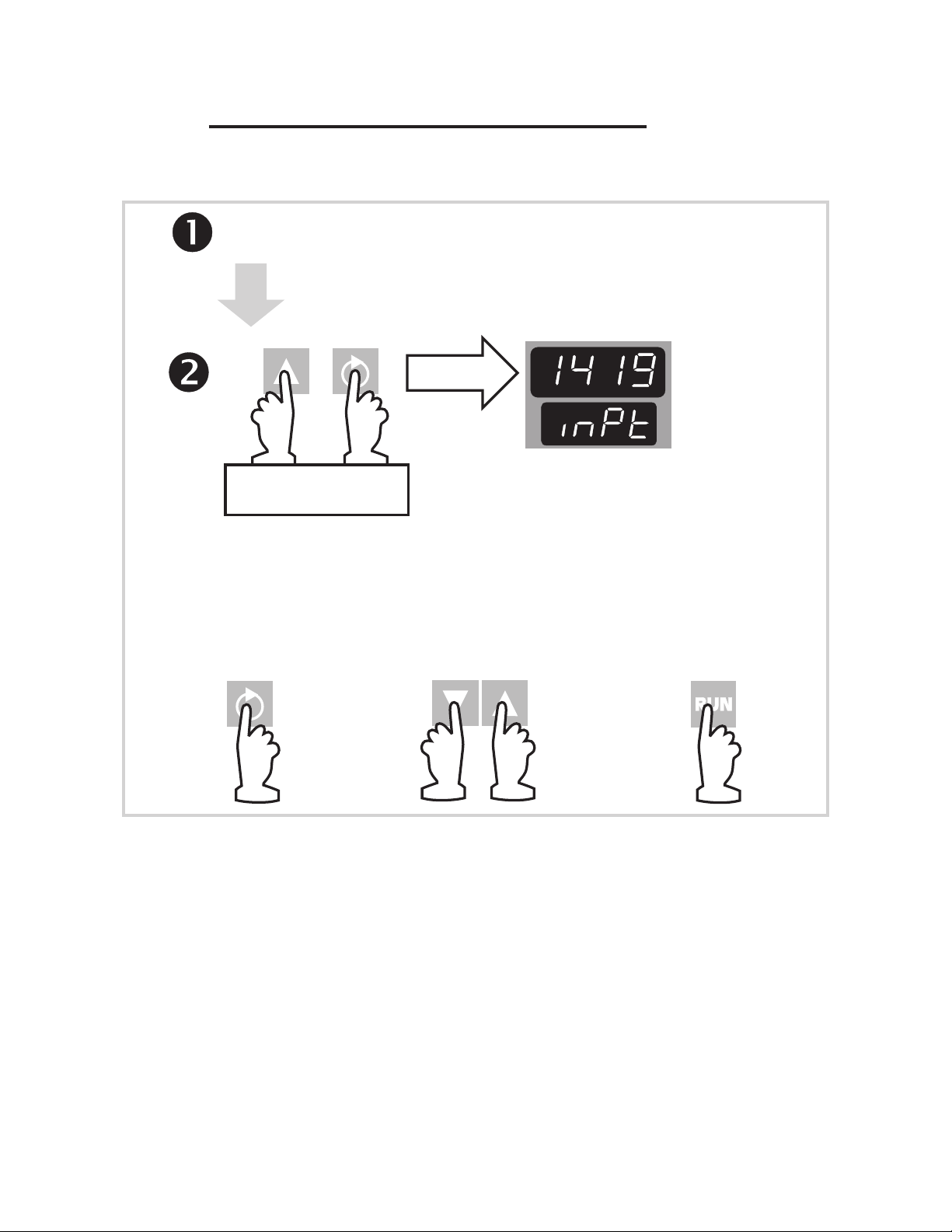
3.1 ENTRY INTO CONFIGURATION MODE
Pow e r-up the Profile C o ntrolle r.
Within 30 secs. as 1st
key action after power-up.
To di spl ay
HOLD DO WN
SIM U LTA N EO U S LY
For five seconds
In Configurat ion Mode:
To s el ec t
parameter
To c hange val ue
(upper display flashes)
Va l u e
Identifier
Profile Controller is in
Configuration Mode and
displays current input code
To c on fi r m new
value (upper
display is static)
Figure 3-1 Entry into Configuration Mode
NOTE: Changes to the value/setting of certain Configuration Mode
parameters (e.g. input range, output use and type) will cause the Set
Up Mode parameters to be automatically set to their default values
the next time Set Up Mode is entered (see also Volume II, beginning
of Section 2).
3.2 HARDWARE DEFINITION CODE
This parameter is a special facility in Configuration Mode, which is used to
represent the hardware fitted (input type, Output 1 type, Output 2 type and
Output 3 type); this must be compatible with the hardware actually fitted. For
access to, and adjustment of, the Hardware Definition Code, see Figure 3-2 and
Table 3-1.
S077-3 Volume I 3-1
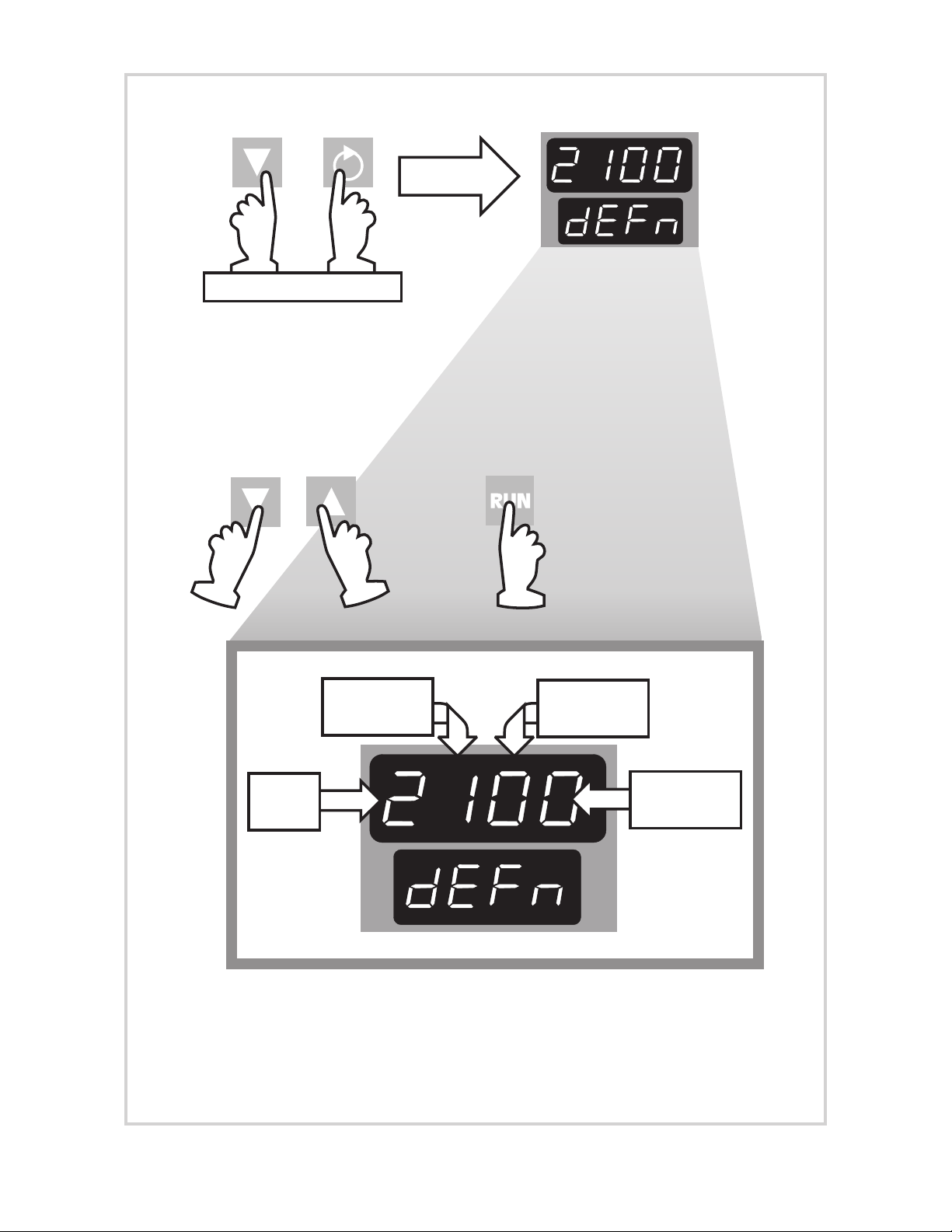
C
urrentHardwar e
In Conf igurat ion Mode:
Defini tion Code
To di spl ay
SIM U LTA N EO U S LY
Use these keys also to return
to Configuration Mode.
With Hardware Definition Code displayed:
To conf ir m new
To change val ue
(upper display flashes)
value (upper
display is static)
OR
Input
Type
Output 1
Type
See also Table 3-1
Output 2
Type
Output 3
Type
Figure 3-2 Hardware Definition Code - Access and Adjustment
3-2 Volume I S077-3
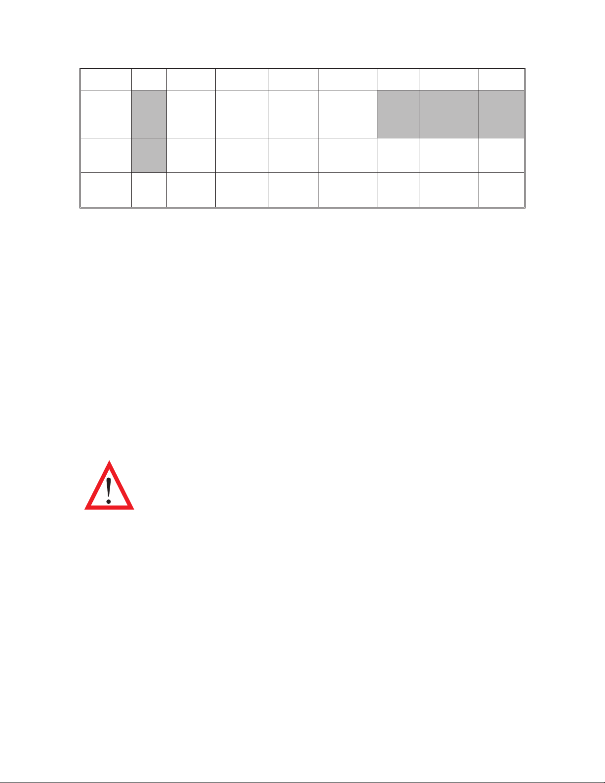
Table 3-1 Hardware Definition Code - Input/Output Type Selection
Value 0 1 2 3 4 5 7 8
Input RTD/
Linear
DC mV
Output
1
Output
2/3
Not
fitted
Relay SSR
Relay SSR
Thermocouple
Drive
Drive
Linear
DC mA
DC
0 - 10VDC0 - 20mADC0-5VDC4 - 20mA
DC
0 - 10VDC0 - 20mADC0-5VDC4 - 20mA
Linear
DC V
* Output 2 only
NOTES:
1. If Output 2 is a relay/SSR drive/solid state output, it may be a control
output (COOL), an event output or an alarm output; if it is set to be a DC
output, it can only be a control output (COOL).
2. If Output 3 is a relay/SSR drive output (it cannot be a solid state output),
it can only be an event output or an alarm output; if it is set to be a DC
output, it can only be a recorder (i.e. retransmitted process variable or
setpoint) output.
Solid
State
Solid
State*
The maximum setting available for this code is 4887. For example, the code for a
thermocouple input, DC 4 - 20mA primary output (Output 1) and relay Output 3
would be 2701.
NOTE: It is essential that this code is changed promptly
whenever there is a change to the instrument’s hardware
configuration (change of input/output type, alarm/recorder
output added/removed etc.). The instrument software depends
upon this code to ensure that the instrument operates
correctly.
This code may be viewed as a Read Only display in Base Mode (see Volume II,
Subsection 1.11).
3.3 OPTION SELECTION
This indicates the option fitted (Communications Option, Remote Run/Hold option
or no option at all). It is accessed whilst the Hardware Definition Code is
displayed (see Figure 3-3).
S077-3 Volume I 3-3
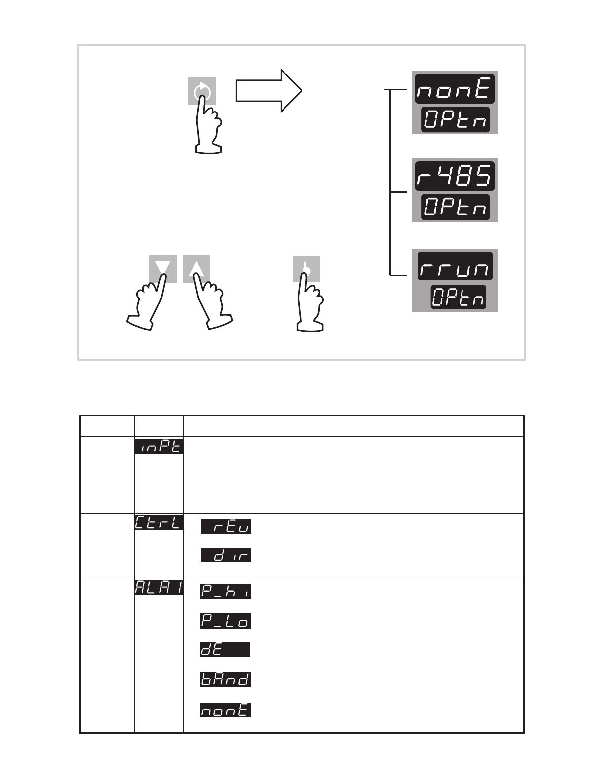
With Hardw are Definition Code displayed:
To di spl ay
Use this key also to return to
the Hardware Definition Code
To confi r m new
To change selection
(upper display flashes)
selection (upper
display is static)
OR
Figure 3-3 Option Selection
One of three
No option
RS485
Rem ote
Run/Hold
3.4 CONFIGURATION MODE PARAMETERS
Parameter Identifier Description
Input
Range
Output
1
Action
Alarm 1
Type
A four-digit code (see Appendix A). Default settings:
Thermocouple - 1419 (Type J, 0 - 761°C)
RTD/Linear mV - 7220 (RTD Pt100 0 - 800°C)
Linear mA - 3414 (4 - 20mA)
Linear V - 4446 (0 - 10V)
Reverse-acting
Direct-acting
Process High Alarm
Process Low Alarm
Deviation Alarm
Band Alarm
No alarm
3-4 Volume I S077-3
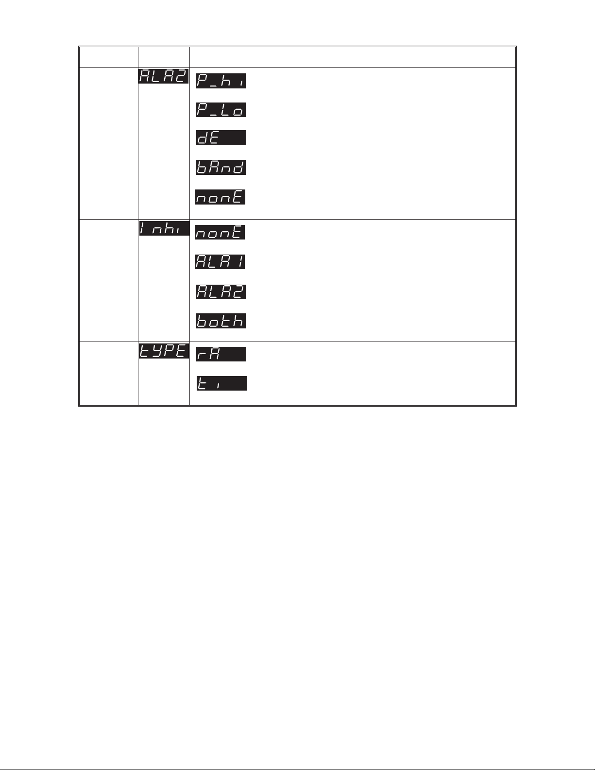
Parameter Identifier Description
Alarm 2
Type
Alarm
Inhibit
Program
Mode
Process High Alarm
Process Low Alarm (default)
Deviation Alarm
Band Alarm
No alarm
No alarms inhibited
Alarm 1 inhibited
Alarm 2 inhibited
Both Alarm 1 & Alarm 2 inhibited
Rate
Time
S077-3 Volume I 3-5
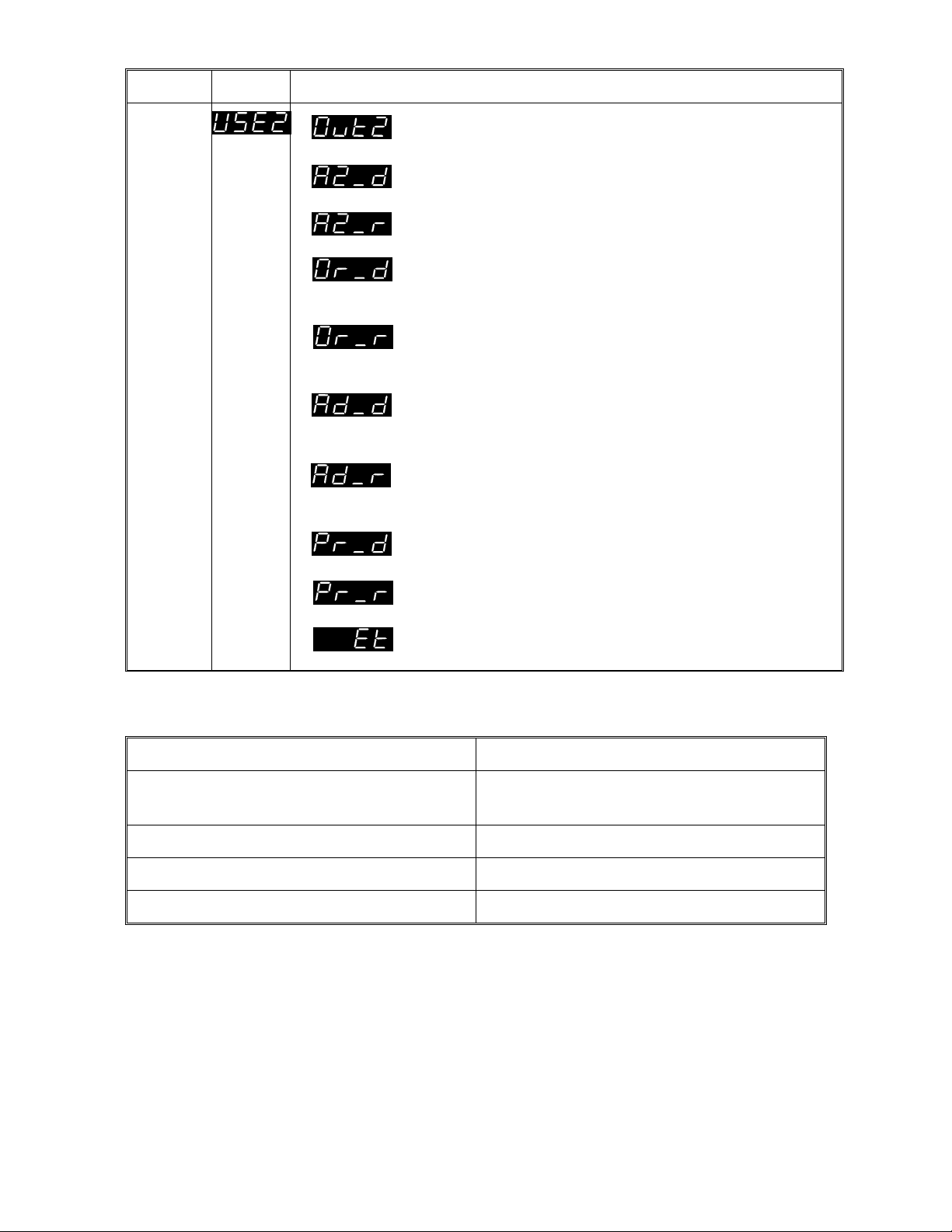
Parameter Identifier Description
Output
2
Usage
Output 2 secondary control (COOL) output
Alarm 2 hardware output, direct-acting. Available only if relay/SSR drive/solid state output.
Alarm 2 hardware output, reverse-acting. Available only if relay, SSR drive or solid state output.
Direct-acting output for Logical OR of Alarm 1
and Alarm 2. Available only if relay, SSR drive,
or solid state output.
Reverse-acting output for Logical OR of Alarm 1
and Alarm 2. Available only if relay, SSR drive,
or solid state output.
Direct-acting output for Logical AND of Alarm 1
and Alarm 2. Available only if relay, SSR drive,
or solid state output.
Reverse-acting output for Logical AND of Alarm
1 and Alarm 2. Available only if relay, SSR drive,
or solid state output.
Profile Active output, direct-acting. Available
only if relay, SSR drive or solid state output.
Profile Active output, reverse-acting. Available
only if relay, SSR drive or solid state output.
Event output, direct-acting. Available only if
relay, SSR drive or solid state output.
Example of Logical Combination of Alarms - Logical OR of Alarm 1 & Alarm 2.
Direct-acting Reverse-acting
AL1 OFF, AL2 OFF: Relay
de-energised
AL1 OFF, AL2 OFF: Relay
energised
AL1 ON, AL2 OFF: Relay energised AL1 ON, AL2 OFF: Relay de-energised
AL1 OFF, AL2 ON: Relay energised AL1 OFF, AL2 ON: Relay de-energised
AL1 ON, AL2 ON: Relay energised AL1 ON, AL2 ON: Relay de-energised
3-6 Volume I S077-3
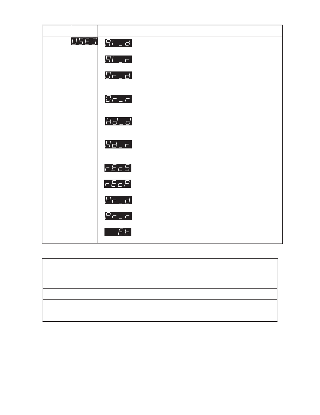
Parameter Identifier Description
Output
3
Usage
Alarm 1 hardware output, direct-acting. Available only if relay/SSR drive/solid state output.
Alarm 1 hardware output, reverse-acting. Available only if relay, SSR drive or solid state output.
Direct-acting output for Logical OR of Alarm 1
and Alarm 2. Available only if relay, SSR drive,
or solid state output.
Reverse-acting output for Logical OR of Alarm 1
and Alarm 2. Available only if relay, SSR drive,
or solid state output.
Direct-acting output for Logical AND of Alarm 1
and Alarm 2. Available only if relay, SSR drive,
or solid state output.
Reverse-acting output for Logical AND of Alarm
1 and Alarm 2. Available only if relay, SSR drive,
or solid state output.
Recorder Output - Setpoint (DC output only)
Recorder Output - Process Variable
(DC Output only)
Profile Active output, direct-acting. Available
only if relay or SSR drive output.
Profile Active output, reverse-acting. Available
only if relay or SSR drive output.
Event output, direct-acting. Available only if
relay or SSR drive output.
Example of Logical Combination of Alarms - Logical AND of Alarm 1 & Alarm 2
Direct-acting Reverse-acting
AL1 OFF, AL2 OFF: Relay
de-energised
AL1 OFF, AL2 OFF: Relay
energised
AL1 ON, AL2 OFF: Relay de-energised AL1 ON, AL2 OFF: Relay energised
AL1 OFF, AL2 ON: Relay de-energised AL1 OFF, AL2 ON: Relay energised
AL1 ON, AL2 ON: Relay energised AL1 ON, AL2 ON: Relay de-energised
S077-3 Volume I 3-7
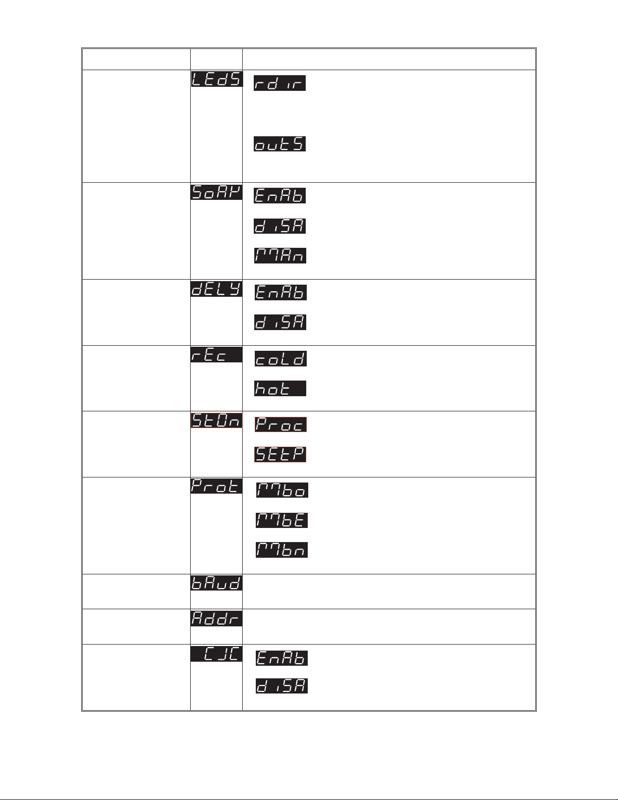
Parameter Identifier Description
D & Ñ LEDs
Usage
(on Front Panel)
Guaranteed Soak
Enable/Disable
(see Volume II,
Subsection 3.2.5)
Delayed Start
Enable/Disable
Power Loss
Recovery
Ramp direction:
D = positive ramp
Ñ = negative ramp
both = soak
Output state:
D = Output 1 ON
Ñ = Output 2 ON
Enabled
Disabled
Manual
Enabled
Disabled
Cold Start (program re-started from
beginning)
Warm Start (program resumed from
point at which power failed)
Start On Start program with setpoint at
current process variable value
Start program with setpoint at
Controller Setpoint value
Communications
MODBUS with odd parity
Protocol
MODBUS with even parity
MODBUS with no parity
Communications
Selectable: 1200, 2400, 4800, 9600 Baud
Baud Rate
Communications
Address
Cold Junction
Unique address assigned to the Profile Controller;
in the range 1 - 255.
Enabled (default)
Compensation
Enable/Disable*
Disabled
* Appears only if a thermocouple input is selected (see Hardware Definition Code).
3-8 Volume I S077-3
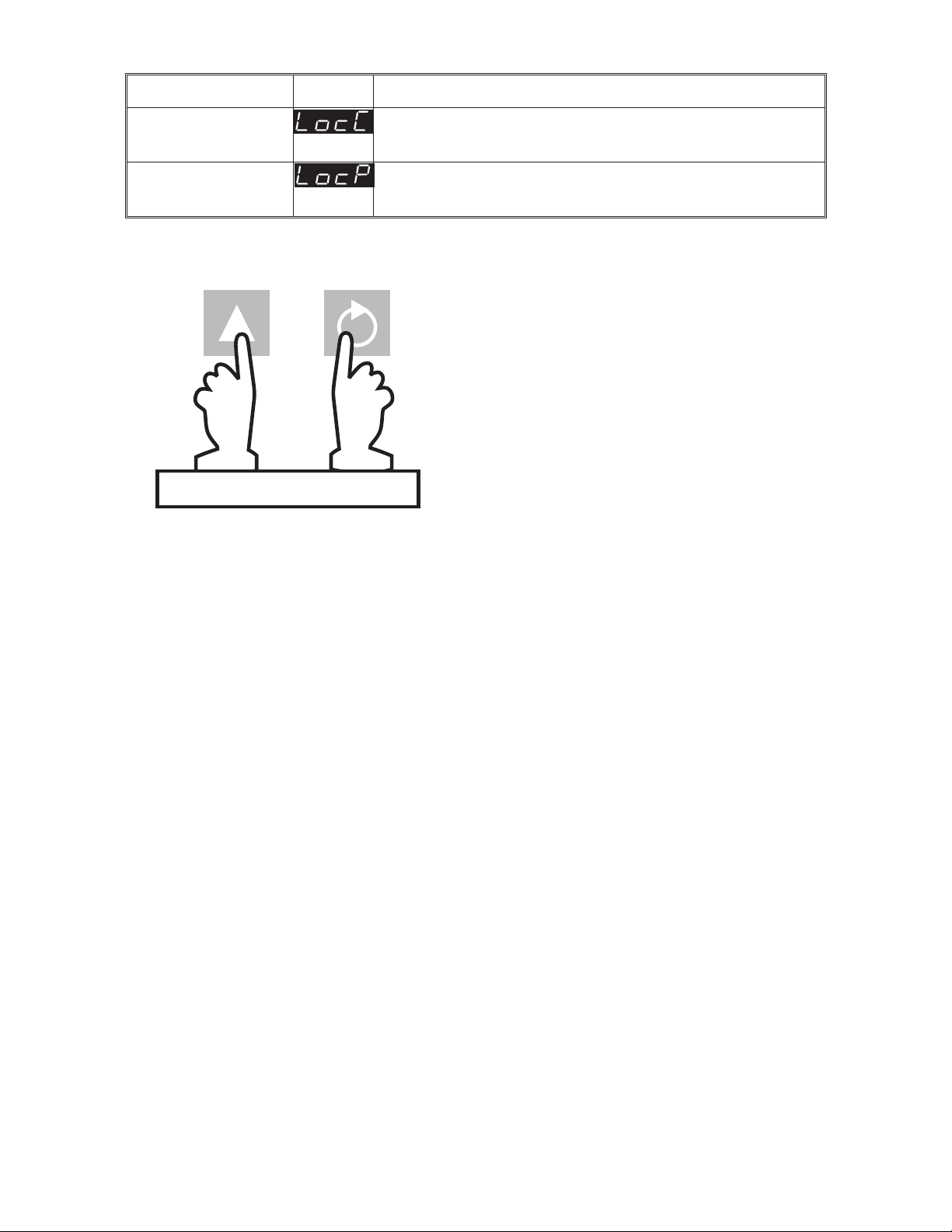
Parameter Identifier Description
Controller Set-Up
Mode Lock Code
Program Define
Mode Lock Code
Read Only display of current four-digit Set Up
Mode Lock Code.
Read Only display of current four-digit Program
Define Mode Lock Code.
3.5 EXIT FROM CONFIGURATION MODE
NOTE: An automatic exit to Operator
Mode will be made if, in Configuration
Mode, there is no front panel key
activity for two minutes.
The exit is made via the power-up self-test
routines which include a lamp test.
SIMU LTA N EO U SLY
S077-3 Volume I 3-9

1
-DIN RAMP/SOAK PROFILE CONTROLLER
16
PRODUCT MANUAL
VOLUME II
OPERATING INSTRUCTIONS
In normal operation, the operator must not remove the Ramp/Soak
Profile Controller from its housing or have unrestricted access to the
rear terminals, as this would provide potential contact with hazardous
live parts.
Installation and configuration must be undertaken only by
technically-competent servicing personnel. This is covered in Volume I
of this manual.
CONTENTS
1 BASE MODE 1-1
1.1 DISPLAY SEQUENCE - NO PROGRAM RUNNING 1-1
1.2 STARTING A PROGRAM 1-2
1.3 PUTTING A PROGRAM IN HOLD 1-2
1.4 RELEASING A PROGRAM FROM HOLD 1-2
1.5 ABORTING A PROGRAM 1-2
1.6 DISPLAY SEQUENCE - PROGRAM RUNNING 1-3
1.7 RaPID CONTROL FEATURE 1-4
1.8 PRE-TUNE FEATURE 1-4
1.9 ENGAGING BOTH PRE-TUNE AND RaPID FEATURES 1-5
1.10 INDICATION OF PRE-TUNE AND RaPID STATUS 1-5
1.11 VIEWING THE HARDWARE DEFINITION CODE 1-6
1.12 MANUAL CONTROL 1-7
PM077-V2 Volume II (i)