

Page 1

Page 2

lenueV\l 6u!~eJado
6UnJ!8IUes6unU8!p8B
!o/dwa,p apojIV
.AI46noJO4~ lenuew S!4~
peeJ eseeld '~!un S!4~ 6u!~eJedo eJo~e8
Bw4euqB!J~Bqul JBp JOII B!S UBSBl
4:>Jnp WeS'tJBWJne 6Un~!BIUV BSB!P
I 9J1-1-9W 9P 1-Ue/\v
IU9W9/\!1-U91-1-e 9J!1
'9:J!/\J9S U9 1!9Jedde,
"!OldW9,P 9pOW 9:J :
llOJJuo:) pUB Ju9W9JnSeew ss9:JOJd JoJ peeN I 6u!LlJAJ9A3 PU!:l1 °0 eJeLiM
9SJno:) JO ...YD3WO
sw9~sAS 1994M9IPped/9U!qJn.L .3yn.LVY3dW3.L
'SJO~:J9UUO:) 's9qOJd
SJ9110J~uo:) 4:J~e8 13 sJ9z!le~°.L. JO~S!WJ94.L 13 a.L~ '9Idno:JoWJ94.L .
A.L1/\1.L:)nONO:)/Hd S9!lqw9SSV 13 sI9ued
S9!JOSS9:J:JV JO~S!WJ94.L 13 a.L~
3:)YO:l ONY NIYY.LS '3ynSS3Yd
~u9wd!nb3
9JeMjJos SJ9:JnpSUeJ.L~U9W9:Jelds!a .
sw9~sAS
13 SJ9~S9.L 'S9pOJ~:J913 Hd .'9Idno:JoWJ94.L :9J!M .
SJ9~9V11AJo~eJoqel/do~4:JU98. S9:JU9J9J9~ ~U!Od 9:J1 13 sJO~eJq!le:) .
'sJO~eJq!le:) 'SJ9110J~UO:) .ss9:JOJd 13 SJ9110J~uo:) 'SJ9pJO:J9~ .
sdwnd 13 sJo~elnw!s SJO~!UOVII
A~!I\!~:Jnpuo:) 13 Hd le!J~snpul .SJ9~9WOJAd p9JeJJui .
NOI.LISlnU:)Y Y.Lya s96neD u!eJ~S 13 SJ9:JnpSUeJ.L .
6U!J99U!6U3 13 Uo!~!s!nb:JV e~ea .s96neD 9JnSS9Jd 13 S119:) peal .
Uo!~!s!nb:JVP9se8-SUO!~e:J!unwwo:) .S9!JOSS9:J:JV 13 uo!~e~u9wnJ~sul .
SH3.LWH
~U9W~e9J.l
9lqe:) 6U!~e9H .
SJ9~e9H 9Iq!X91,j .
sJe~eeH d!J~S q 96P!J~e:) .
SJ9~e9H AJo~eJoqel .
10H.LNO:>ONV
SJ9~9WO~eJ!9~ .
6u!qn.l q sdwnd .
S~U9WnJ~SUI u96AxO
SJ9~e9H pueg q UO!SJ9WWI .
DNIHO.LINOW1V.LN3WNOHI/\N3
uo!~e~ueWnJ~suIIOJ~uO:) q 6u!Je~eVIJ .
SJO~!uoVIJ J9~eM q liaS 'J!V .
J9~eM9~SeM q J9~eM le!J~snpul .
P9/\IOSS!O q A~!/\!~:>npuo:) 'Hd .
'91ddv JoJ spJe:) u!-6nld .13/\31 ~ M01:1
s9Iq!~edwo:) 13 VII 8 I SJ9~9WMOI:J sse VII seD 'SJ9~9We~o~ .
sw9~sAS 6u!66ole~ea .sJ9~ndwo:) Mol:J 13
SJ9~~Old 13 SJ9~U!Jd 'SJ9pJO:J9~ .SJO~e:J!pUI A~!:JOI9J\ J!V .
9690n917l~
96. J9qW9jd9S "qnd /'':"IN ""9/{/9t 99Z' #
Page 3
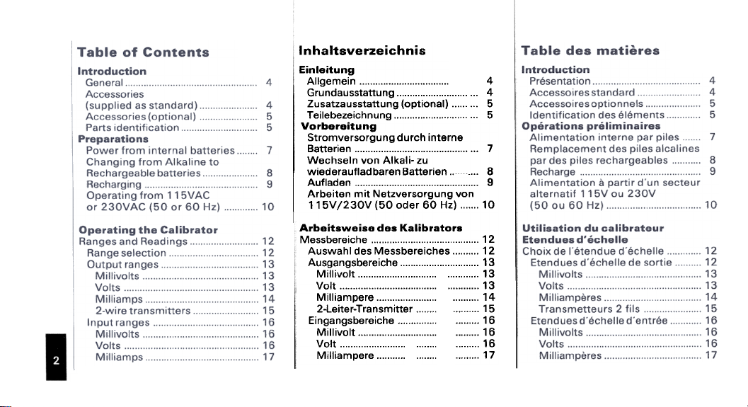
Inhaltsverzeichnis
Einleitung
Allgemein 4
Grundausstattung 4
Zusatzausstattung (optional) 5
Teilebezeichnung 5
Vorbereitung
Stromversorgung durch interne
Batterien 7
Wechseln von Alkali- zu
wiederaufladbaren Batterien 8
Aufladen 9
Arbeiten mit Netzversorgung von
115V /230V (50 oder 60 Hz) 10
Arbeitsweise des Kalibrators
Messbereiche 12
Auswahl des Messbereiches 12
Ausgangsbereiche 13
Millivolt 13
Volt 13
Milliampere 14
2-Leiter-Transmitter 15
Eingangsbereiche 16
Millivolt 16
Volt 16
Milliampere 17
Page 4

epow tes
epow tndtno
SUO!Je3!l!3SdS
SJett!WSUeJt eJ!M-Z
lellel tndtno e4t 6u!6ue4:)
pedAe>lle:>!JeWnU 4t!M
sdets uo!teJq!le:> PBX!:!
sde~s dn 6u!~tes
sde~s ~nd~no °.l
6u!dweJ :>!~ewo~n"
sdweJ dn 6u!~~es
sdweJ ~nd~no °.l
8~ed pUB A!edsA 'S:I!AASS
~S!I s~ed 9Jeds
H3WI~:>Slal A.LNWH"M
LL
8L
'..' '..,eu6!s e tnd~no °.l
8L
8L
6L
6L
sAe>l 1'/~ uMop/dn 4t!M
6L
snpows6ue6sn'tj
OZ
OZ
ZZ
£Z
£Z
tZ
9"l
Ll
6u!pu!! ~Ine! pue UO!~eJq!le:>-91:1
££
pun AnJe.ledoH 'O:J!J\A9S
v£
9£
L l Jeu!wsueJJ.-Jo~!el-Z
8l Sleu6!s Sou!e ueqe6sn'tj
8l (snpoll'J J.3S) snpowlle~su!3
8l (snpoll'J J.ndJ.nO)
6l se~eMeqe6sn'tj sop ules4:JeM
6l ue~se~uJewwnN Uop ~!II'J
6l """"""'1'/-!- ue~se~I!O!d uep ~!II'J
OZ OU!J4:JSJe!Jq!le)l e~se:J
OZ e~~!J4:JS Jep uelle~su!3
ZZ e~~!J4:JS Jep ueqe6sn'tj
£Z uO!~>lun!uedwe~e4:JS!~eWo~n'tj
£Z edwe~ Jep uelle~Su!3
vZ edwe~ Jep ueqe6sn'tj
9Z """"",.,..,."""""""""""""" °1!°JzJesA3
LZ e4:JnsJeI4e:J pun 6urue!Jq!le>l4:JeN
££ e~s!lel!e~~esJ3
v£ U9UO!Je>ly!zodS
9£ H3WIV1:>SIC/A.lNWH"M
L L Sl!! l Jne~~ewsueJ.L
8L leUD!S un.p uo!~eJ~u~~
8 L eDeID~J epoVli
np epn~!ldwe.1 ep eDelD~ij
~e uo!~e.led9.1 'ue!~e.l~u3
8 L e!~os epoVli
6 L e!~Jos ep leUD!S
6L enb!J~wnu Je!l\el:J np ep!e.1 V
6L 'f'/-lt se4:Jno~ ssp ep!e.1 V
Ol eDeuuole~~.p sex!! S~U!Od
Ol ...sex!! s~u!od epow ue eDessed
U sex!! s~u!od ssp uo!~ewWeJDOJd
£l enb!~ewo~ne edweij
£l adweJ eun.p uo!~ewWeJDOJd
vl sadweJ sap JaJ~U~D JnOd
9l se:l~!d ep epuewwo:l
a aDeuued~p ~a aDeuuole~3
££ sa:J~!d sap a~s!l
v£ sanb9S!.I~~:le.le:>
9£ H3WIV1:>SIC/AJ.NWH'rIM
Page 5
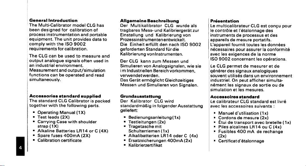
General Introduction
The Multi-Calibrator model CLG has
been designed for calibration of
process instrumentation and portable
equipment. The unit provides data to
comply with the ISO 9002
requirements for calibration.
The CLG can be used to measure and
output analogue signals often used in
an industrial environment.
Measurement and output/simulation
functions can be operated and read
simultaneously.
Accessories standard supplied
The standard CLG Calibrator is packed
together with the following parts.
.Operating Manual (1X)
.Test leads (2X)
.Carrying Case with shoulder
strap (1X)
.Alkaline Batteries LA 14 or C (4X)
.Spare fuses 400mA (2X)
.Calibration certificate
Allgemeine Beschreibung
Der Multikalibrator CLG wurde als
trag bares Mess- und Kalibriergeriit zur
Einstellung und Kalibrierung van
Prozessinstru menten entwickelt.
Die Einheit erfullt den nach ISO 9002
geforderten Standard fur die
Kalibrierung vonlnstrumenten.
Der CLG kann zum Messen und
Simulieren van Analogsignalen. wie sie
i m Industriellen Bereich vorkommen.
verwendetwerden.
Das Geriit ermoglicht Gleichzeitiges
Messen und Simulieren van Signalen.
Grundausstattung
Der Kalibrator CLG wird
standardmaBig in folgender Ausstattung
geliefert:
.Bedienungsanleitung(1x)
.Testleitungen (2x)
.Tragetasche mit
Schulterriemen (1x)
.Alkalibatterien LA 14 oder C (4x)
.Ersatzsicherungen 400mA (2x)
.Kalibrierzertifikat
Presentation
Le multicalibrateur CLG est con9u pour
Ie contr61e et I'etalonnage des
instruments de processus et des
appareils de mesure portatifs.
L'appareil fournit to utes les donnees
necessaires pour assurer la conformite
avec les exigences de la norme
ISO 9002 concernant les operations.
Le CLG permet de mesurer et de
generer des signaux analogiques
souvent utilises dans un environnement
Industriel. On peut afficher simulta-
nement les signaux de sortie ou de
simulation et les mesures.
Accessoires standard
Le calibrateur CLG standard est livre
avec les accessoires suivants :
.Manuel d'utilisation (1x)
.Cordons de mesure (2x)
.Etui de transport avec bretelle (1 x)
.Piles alcalines LR 14 ou C (4x)
.Fusibles 400 mA de rechange
(2x)
.Certificatd'etalonnage
Page 6
S9!,IOSS9:J:JR ,Ruondo
/Jo~depv 9U!1I\OEZ .
OEZ/Sd81:)J96Je4:)
9https://manualmachine.com/Sd81:)
:Jeq.l8J8!1 LI:>!lzJ~snz
J96Je4:)/Jo~depv 9U!ll\g ~ ~ .
9LL/Sd81:>
OEZ/Sd81:>
~!1Je6epel/-z~eN 1\ OEZ .
~!1Je6epel /-z~eN 1\ 9 L L .
Sl8UUondo S8~!OSS8:J:JV
Jne6Je4:>/Jne1-:>esepJne1-e1-depv .
OEZ/Sd81:) e:>ueJ~!~J /\OEZ
Jne6Je4:>/Jne1-:>esepJne1-e1-depv .
9 L L /Sd81:) e:>ueJ~!~J /\9 L L
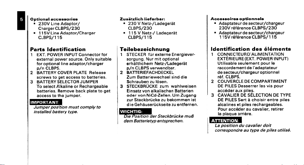
UO!~&:)!I!~Uepl SJA&d
'Sd81'J u/d
"J9dwn! 94~ o~ SS9:>:>e
_..'~7'.:[.r:1'.'11
"9dAJ AJ9JJeq p9ffeJsU!
6unUII:)!8z8q81!8.l !
JO! JO~:>9UU°'J .lndNI ij3MOd ".lX3 L
9Iqe~!ns AIUO "9:>Jnos J9MOd leUJ9~X9
J96Je4:>/Jo1.depe 9U!lleUO!~do JO!
9se919ij 3.l'l7'1d ij3/\O'J Aij3.l.lV8 "l
"S9!J9~~eq O~ SS9:>:>e 1.96 01. SM9J:>S
ij3dVIJnr ijO.l'J313S Aij3.l.lV8 £
91qe96Je4:>9ij JO 9U!le>lIV ~:>919S °.l
~96 O~ 9~eld >I:>eq 9/\OW9ij "S9!J9~~eq
OJ Afdwoa Jsnw uo!J!sod J9dwnr
'Jeqpu9MJ9/\Sd81:> u/d
13>1:>3aH:>V:l31~3.L1V8 Z
'U9SQI nz u9qneJ4:JS
-J9/\9!CJ9U3 9UJ91-X9 JO~ ~3>1:>3.LS I-
leUo!1-do 1-!W JnN "cuncJos
1-!!J9C9pel/-n9N w94:J!I1-I!!4J9
9!P PUIS 19S4:J9M9!J9"e8 wnz
U9S!9MI4eM wnz 3>1:>n~8>1:>3.LS £
U9!J91-1-e8 u94:Js!le>jle UO/\ nesu!3
cuecnz Wn 'U9119Z-P:>!N UO/\ J9pO
IS91!d 9JlU9 J!S!Olj:> ~ lJ9S S31ld 30
1-S! U9WWO>j9q nz 9>j:JOJq>j:J91-S JnZ
'U9UJ9~1-U9 nz 91-!9S>j:JOJ9Sn!!49~ 9!P
fJnw 9>1:J!]Jq>l:J91S J9~~~~:!~.,.,
'U91j:J9JdS1U9 dA19!J9neg W9p
'Sd81:> '~~J
'S91!d xne J9p~:>:>e
'9J~!JJe 9nbeld el
-,,[.].~,,~..,-;.
J!OP J9!feAea np uo!J!sod e7
sJuaw'I' sap UO!J8:J!J!Juapl
NOIIVIN3i1"IlV.0~n31:>3NNO:> L
UndNI ~3MOd 'lX3)3~n31~31X3
91 Jnod lU9W91n9S 9IQeS!I!ln
Jn9leldepe.19p lU9W9pJO:>:>eJ
19UUO!ldo Jn95Jelj:>/ Jn9l:>9S 9P
IN3i1"ll~Vdil"O:>30 31:>~3J\nO:> Z
Jnod S!/I s91 J9JJ9SS90 S31ld 30
3dAJ. 30 NO11:>313S 30 ~3IlVJ\V:> £
'S9Iqe95Jelj:>9J S91!d 19 S9U!le:>le
J9J!l9J .J9!le/le:> ne J9p~:>:>e Jnod
'f1S!f!Jn S9f!d 9P 9dAJ ne 9JpUOdS9JJOO
Page 7
r, "_boo~
-" --
-.c
1Ii..
'\
:
.
.
.
:
:
'-,I."'~,,~.
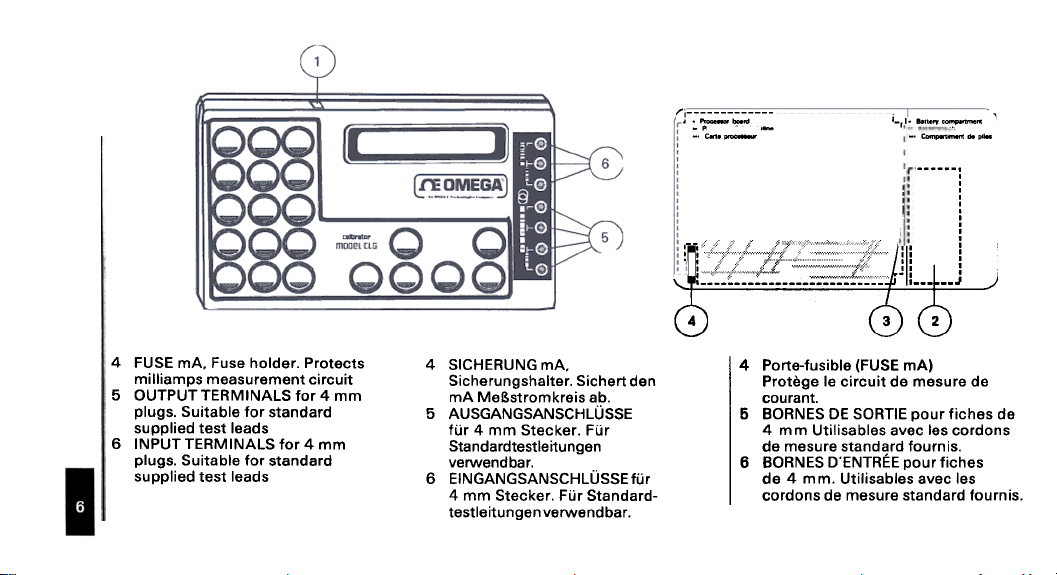
4 FUSE mA. Fuse holder. Protects
milliamps measurement circuit
5 OUTPUT TERMINALS for 4 mm
plugs. Suitable for standard
supplied test leads
6 INPUT TERMINALS for 4 mm
plugs. Suitable for standard
supplied test leads
4 SICHERUNG mA.
Sicherungshalter. Sichert den
mA MeBstromkreis ab.
5 AUSGANGSANSCHLUSSE
fur 4 mm Stecker. Fur
Standardtestie itu ngen
verwendbar.
6 EINGANGSANSCHLUSSEfur
4 mm Stecker. Fur Standardtestieitungen verwendbar.
4 Porte-fusible (FUSE mAl
Protege Ie circuit de mesure de
courant.
5 BORNES OE SORTIE pour fiches de
4 mm Utilisables avec les cordons
de mesure standard fournis.
6 BORNES D'ENTREE pour fiches
de 4 mm. Utilisables avec les
cordons de mesure standard fournis.
Page 8
SUo!te,leds,Id
'9Z!S :) JO Aqea 'V L ij
'uo!~elle~su! 9JO~9q S910d
S9!J9~~eq 9U!le>lIV lo 9Sn
(pJepue~S se p9!lddns)
'Jo~e:l!pu!.. .1va ..6u!>lU!lq
6unJ!aJaqJo/\
se'.leJJeq leu.leJu! WO.lJ .leMod
WOJl p9U!e~qo S! J9MOd leUJ9~ul
Xv JO S9!J9~~eq 9u!le>lIV s~loA g' L Xv
19poVII 'S9!J9~~eq 91qe96Je4:19J s~loA Z' L
noA 9JOl9q llo Jo~eJq!le:l 94~ 4:1~!MS
94~ 9/\OW9ij 'S9!J9~~eq M9U Ile~su!
4~oq 9Se919J pue 9Se:l 6u!AJJe:l
AJ9~~eq 94~ lo SM9J:lS 6u!~unoW
94~ u9dO .J9/\O:l ~u9w~Jedwo:l
M9U 94~ 9:1eld pue ~u9w~Jedwo:l
uo p9~:lnJ~Su! se uo!~!sod U! S9!J9~~eq
AJ9~~eq ue91:1 JOl >1:194:) '9~eld9weu 94~
~9S 9UO 4~!M p9!lddns S! Jo~eJq!le:l 94.1
9:1eld9ij 'S9!J9~~eq 9U!le>lIV Xv lO
94~ SMo4s U99J:lS 94~ U94M S9!J9~~eq
ue!Je~eB
.9Z!S :> J9pO
.910d9!J9~~ea 9J9qnes
.UJ9n9UJ9
eUJ9JU! Lj:JJnp 6un6JoSJ9AWOJJS
u9ssel 6un6JoSJ9/\WOJ~S 9UJ9~U! 9!P J[):I
U9!J9~~ea 94:1s!le>tle A 9'1. x v 4:1!S
9JeqpelJneJ9p9!M A l'l. x v J9pO
Aqea 'v I. ~ 119p°V'J .U9PU9MJ9/\ U9!J9~~ea
W9p JO/\ Jo~eJq!le>l U9p 9!S U9~le4:1S
sep 9!S U9W49N .sne 19S4:19M9!J9uea
pun 94:1Se~96eJ.LJ9p sne ~~J9~
.19>t:l9p4:1eJ9!J9~~ea U9p 9!S U9UJ9J~U9
Jne J9p U! U9!J9~~ea 9!P 9!S U9Z~9S
UO!~!SOd U9~119~S96Jep PI!4:1SU9dA.L W9p
Jne U9Z~9SU!3 W9p JO/\ 9!S U9~4:1V 'U!9
U9!J9uea U94:1s!le>tle Uo/\ 6UnpU9MJ9A
(6UeJWnJ9J9!1 J96!~~wpJepUe~s)
U94:1S!le>tle V ~!W pJ!M JO~eJq!le>l J9a
J9p Jne uu9M .~J9J9!196 U9!J9~~ea
".LVa " 6unpl9V'J 9!P 96!9ZUV
nz U9!J9~~ea 9!P PUIS '~U!94:1SJ9
's9JdoJd
1\(;' L 9P selQee6Je4:JeJ
iJ no 17 L ~ edA~)
(pJepue~s 9Jn~!UJno~)
's9U!le:Jle Sel!d 17 ep
sa..!eU!W!I~..d suo!Je..~do
sel!d .led eu.leJu! uo!JeJuew!IY
Sel!d 17 Jed ~~uew!le ~se 1!9Jedde.1
Sel!d 17 no I\g' L ep s9u!le:Jle
S91!d sap 9:Jeld U9 eJ~~9W ep ~ue/\v
SJ04 Jn9~eJq!le:J el eJ~~ew 's9/\n9u
~9 ~JodsueJ~ ep !n~~.1 J9J!~9~ 'uo!sue~
np uo!~ex!~ 9P S!/\ xn9p sel JeJJ9SS9p
'sel!d 9P ~u9w!~edwo:J np 91:JJ9/\no:J
~e selid 9P ~u9w!~Jedwo:J el J!J/\no
9WWO:J S9/\neu S91!d s91 J9sods!p
'9nb!~~leu6!s 9nbeld el Jns ~nb!pUi
~UOS s~:Je~uo:J s91 enb JeJnsse.s
s9u!le:Jle Sel!d ep uo!~es!I!~n
n9f un :Je/\e !uJno~ ~S9 Jne~eJq!le:J 91
Jn9~e:J!pU!.1 puenb Sel!d S91 J9:Jeldw9~
ueJ:J~.1 Jns ~!eJedde ~ue~ou6!1:J ".LV8"
Page 9
Changing from Alkaline to
Rechargeable batteries
Remove the Alkaline batteries. Release
the 4 coverplate screws and take the
coverplate of. Remove the alkaline
batteries. Place the jumper next to the
compartment in the" CHARGE"
position. Install 4x rechargeable
batteries (purchased locally) and
reinstall the coverplate. Recharge
batteries when the screen shows the
blinking" BAT" indicator or when
the screen remains blank when
switching on.
i"'I":I.'II.'[~
Never use alkaline or other non-
rechargeable batteries when you
have put the jumper into
" CHARGE" position.
Wechsel yon alkalischen- zu
wiederautladbaren Batterien
Entfernen Sie die alkalischen Batterien.
Lbsen Sie die 4 Gehauseschrauben und
entfernen Sie die GehauserUckseite.
Setzen Sie die SteckbrUcke an der
Batteriefachseite in Position" CHARGE
" und lagan Sie die wiederaufladbaren
Batterien in das Batteriefach. Montieren
Sie die GehauserUckseite wieder.
Wenn auf der Anzeige " BAT"
erscheint oder wenn das Display nach
dam Einschalten dunkel bleibt, mUssen
die Batterien nachgeladen werden.
Verwenden SiB niemals alkalische
oder niGht aufladbare Batterien, wenn
siGh die Steckbriicke in Position
" CHARGE" befindet.
Remplacement des piles alcalines
par des piles rechargeables
Retirer les piles alcalines. Desserrer les
4 vis du couvercle. Mettre Ie cavalier
de selection du type de piles dans la
position" CHARGE ". Mettre en place
4 piles rechargeables (achetees
localement) et revisser Ie couvercle.
Recharger les piles quand I"indicateur
" BAT" clignotant apparait sur I"ecran
ou si I"ecran n'affiche rien a la mise
sous tension.
Ne jamais utiliser de piles alcalines
ou autres piles non rechargeables
quand Ie cavalier est dans la position
"CHARGE ".
Page 10
6u!6.1ell:Jey
uepeunv
Sd81~ N/d Je6Jelj~/Jo~depv elj~ asn
esne:> Aew ~u9wd!nba Jalj~o :AIUO
9lj~ >t:>9lj~ "JO~eJq!le:> elj~ O~ e6ewep
e:>eld pue 96e~IO/l BUll pa~e:>!pu!
" 3~~VH~ " alj~ U! lj:>~!MS J96Jelj:>
e~e!JdoJdde alj~ ~:>9UUO~ "uo!~!sod
pue Bull 9lj~ O~ s6nld J96Jelj~/Jo~depv
pue Jo~depe sv 'Jo~eJq!le:> elj~ o~
~uepUed9pU! Alln~ aJe Suo!~:>un~ Je6Jelj:>
aq ue:> JO~eJq!le:> elj~' Jelj~Olj:>e9 WOJ~
ew!~ 6u!6Jelj:>e~ "6u!6Jelj:> 91!ljM pesn
96Jelj:> Iln~ O~ 96Jelj:>s!p e~eldwo:> WOJ~
JO~ 96Jelj:> Aew noA "sJnolj 17 l S!
"sJnolj 17 l uelj~ Je6uOI spo!Jad
~ue!qwe JaMOI ~e ~elj~ a~oN
P~-!N ~o A~!:>ede:> alj~ saJn~eJ9dwe~
"J9MOI AI~ue:>!~!u6!s S! sa!Je~~eq
J!elj~ lj:>eeJ ~ou II!M se!Je~~eq elj~ ~I
SJ nolI 17 l e Je~e A~!:>ede:> lewJou
pue 6u!6Jelj:>s!p el:>A:> 'po!Jed 6u!6Jelj:>
"sew!~ "l ~seel ~e JO~ 6u!6Jelj:>
U9pel!nv wnz 9!S UepU9MJe/\
~~J969pel/-z~9N sep 4:>!I~e!14:>ssne
ueuug>t 9~~J969pel 9JepuV.Sd81:) u/d
.U9J4!)! JO~eJq!le)l we u9P~4:>S nz
~~J969pel/-z~eN we 9!P qo 9!S U9!!)Jd
~S! 6!~4:>!J 6un6JoSJ9AZ~9N 9ueq9696ue
U! J9~le4:>S U9p 9!S U94eJp pun
unu 9!S U9>t:>e~s ." 3~~VH:) " UO!~!SOd
W9p ~!W ~~J969pel/-z~9N sep
e!s U9PU!qJ9A pun U!9 J9>t:>9~SZ~9N U9p
u9pel96 unu pJ!M ~~Je~ sea .JO~eJq!le)l
S9p PU9J4~M uue>t Jo~eJqile)l J9G
9!G .U9pJ9M~Z~nu9q s6ue6JoA9pel
~~Je~ s9U9pel~U9 U!9 J!)! ~!9z9pel
9J96U~1 .U9pun~s V ~ .e:> ~6~J~eq
.~4:>!U ~~J9~ W9p uepe4:>s ue~!9zepel
-e6wn 96!Jp9!U ~ep '9!S ue~4:>ee8
UOA ~~~izede)l 9iP ueJn~eJedW9~s6unq
UU9M .UJ96U!JJ9A 4:>!I~n9p U9119Z-P:)!N
~~J9~ sep ~!9z9pel U9pun~s V ~ 4:>eu
~4:>!9JJ9 ~~~!zede)l 91ewJOu 9U!9S ~4:>!U
sep 9!S u9pel pun u9pel~u9 as '~e4 I
S6J8LjOSY I
'a6Je4:> el ~uepued
"SeJne4 V t ep snld ~uepued
9P Jne~e~depe.1 ~UeW911!Snl:>xa Jes!I!~n
~n°.l"Sd81:) u/d '~~J Jna6Je4:>/Jne~:>as
el J9JO!J~~~p 9P anbs!J 1!9Jedde eJ~ne
Jna~:>es UO!SU9~ el Je!~!JI1/\ "Jna~eJq!le:>
"" 3~~'r/H:) " uo!~!sod el suep
ep e6Je4:> eun sQJde elewJou
Jne6Je4:> np Jne~e~nwwo:> el 9J~~eW ~9
ne Jna6Je4:>/ Jne~e~depe.1 JapJo:>:>e~
sel 9WWO:) "Jne~eJq!le:> ne ~e Jn9~:>9S
~uos Jne6Je4:> ~a Jne~e~depe SUO!~:>uo~
ap eun,l se~uepued~pu! ~uewele~o~
~s!I!~n eJ~@ ~ned Jna~eJq!le:> el 'eJ~ne.1
sap Je6Je4:>eJ Jnod SeJne4 V t ~ne~ 1\
sno/\ .saI16Je4:>~p ~uawe~~ldwo:> Sel!d
e6Je4:> ue Sal!d sal JeSS!el zellnod
seJn~eJ~dwe~ sap ~,nb Je~ou 'r/
Sel!d sap ~~!:>ede:> el 'sesseq se~ue!qwe
set !s 'eJpu!ow ~uewe~~eu ~se P:)-!N
~~!:>ede:> Jnel sed ~ueu6!e~~e,U sel!d
xnep SU!OW ne Jem:>e~~e 'SeJne4 vL
Page 11
If batteries remain weak they should
be replaced. No particular brand for
Ni-Cd is recommended although cells
rated at 2.0 AH have preference over
generally available 1.8 AH cells.
Operating from 115V or
230V line voltage
(50 or 60 Hz)
Use the Adaptor/Charger PIN CLBPS
only; other equipment may cause
damage to the calibrator. Check the
indicated line voltage. Connect the
appropriate Adaptor/Charger plugs to
the line and to the calibrator.
Gerat mindestens zweimal hinter-
einander. Sollte dies niGht helfen.
so sind die NiCd-Zelien zu wechseln.
Es konnen aile handelsublichen NiCdZellen verwendetwerden. Es sind
jedoch Zellen mit einer Kapazitat van
2.0 Ah den gangigen Zellen mit
1.8 Ah vorzuziehen.
Arbeiten mit Netzversorgung
230/115V
(50 oder 60 Hz)
Verwenden Sie zum Aufladen
ausschlieBlich das Netz-/Ladegerat
pin CLBPS. Andere Ladegerate konnen
zu Schaden am Kalibrator fuhren.
Prufen Sie ob die am Netz-/Ladegerat
angegebene Netzversorgung richtigist.
Stecken Sie nun den Netzstecker ein
und verbinden Sie das Netz-/Ladegerat
mit dem Kalibrator.
cycles de decharge et de recharge.
Si les batteries restent faibles. il taut
les rem placer. La marque de pile Ni-Cd
est indifferente. mais les piles de 2.0
AH sont preferables aux piles de 1.8
AH.
Alimentation a partir d'un secteur
alternatif 115 V ou 230 V
(50 ou 60 Hz)
Utiliser exclusivement radaptateur de
secteur/chargeur ref. pin CLBPS.
Tout autre appareil risque de
deteriorer Ie calibrateur. Verifier la
tension secteur indiquee. Raccorder
radaptateur de secteur/chargeur au
secteur et au calibrateur.
Page 12
"ln9U.l9
JOleJq!le:J aliI 6u!leJado
sap as!aMSI!aq.l''
.lnaJe.lq!le:> np UO!JeS!I!Jn
s.lole.lq!le>l
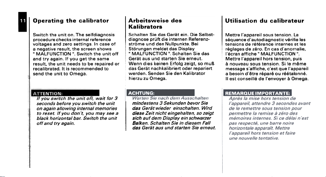
s!sou6e!p~19S 94.l"UO ~!Un 94~ 4:>~!MS
9:>UeJe~eJ leUJe~U! s>t:>e4:> 9Jnp9:>OJd
~O 9Se:> UI .s6u!~~es OJez pUB se6e~IOJ\
SMO4S ueeJ:>s e4~ '~lnS9J eJ\!~e69U e
~~O ~!Un e4~ 4:>~!MS "" NOI.l:>Nn,jlVV\I "
9WeS e4~ ~e6 noA ~I 'u!e6e AJ~ pUB
JO peJ!edeJ eq O~ speeu ~!Un e4~ '~lnS9J
"e6ewo o~ ~!un e4~ pUBS
O~ pepuewwo:>eJ S! ~I "pe~eJq!le:>eJ
'eB9WO nz nzJ9!4
Aelds!G sep ~9P19W u9BunJ9~S
E: JOj J!eM :))0 J!un al/J I/:JJ!MS noA)/
J!un al/J I/:JJ!MS noA aJojaq SpUO:J8S
S8!JOWaW /eUJ8JU! iJU!MOl/e u!eiJe uo
e 8as Aew noA 'J.UOP noA j/ .JasaJ OJ
J!un al/J I/:JJ!MS .Jeq /eJuOZ!JOI/ Jf:Je/q
.u!eiJe AJJ pue JJo
-~SqI9S 9!G 'U!9 ~!1J9~ sep 9!S u9~le4:>S
-ZU9J9!9~ U9UJ9~U! 9!P ~OJd 9souBe!p
!98 '9~)jundlinN U9p pun 9W9J~S
sep 9!S u9~le4:>S'" NOI.L:JNn:llVVIJ "
'~n9UJ9 9!S U9~e~s pun sne ~!1J9~
~nw os '~B!9Z B10!J3 U9U!9)j S9!P uu9M
~9!Jed9J J9pO ~9!Jq!le)j4:>eu ~!1J9~ sep
JO~eJq!le)t U9p 9!S U9PU9S 'U9pJ9M
9fS .l01\9q U9punJf9S E: SU9lS9PUfW
P.lfM "U9llel/:Jsuf9 .l9P9fM lfl.l9,9 sep
lfJf9Z os 'U9llel/9fJuf9ll/:JfU lf9Z 9S9fP
.l9Z.leMl/:JS Uf9 AeldsfO W9p Jne l/:JfS
lIed W9S9fP Uf 9fS u9llel/:JS "U9Jfleg
9fS U9l.lelS pun sne lfl.l9,9 sep
el 'uo!sua~ snos l!aJedde.1 9J~~9V11
S919!J!J~/\ :>!~sou6e!po~ne.p 9:>u9nb~s
s91 ~9 S9UJ9~U! 9:>U9J~J~J 9P suo!sua~
'a!lewoue.p se:> U3 'OJ~Z 9P s96e16~J
." NOI.l:JNn,jlVVII " 9lj:>!ue ueJ:>~,1
sind 'uo!sua~ SJOlj l!aJedde.1 aJ»aVII
aw~w al !S 'uo!sua~ snos nea/\nou ~
1!9Jedde.1 anb ~S9.:> 'alj:>!JJe,s 96essaw
'~uuole~~~J no ~Jed~J 9J~~,p U!OS9q e
'e6awo ~ JaAo/\ua.1 ap ~11!asuo:> ~sa II
Page 13

! Ranges and Readings
Range selection
After completion of the selfdiagnosis
the screen shows:
NONE NONE
indicating that neither an input nor an
output range has been selected yet.
Press" RANGE SELECT IN" to scroll
the measurement ranges.
Press" RANGE SELECT OUT" to scroll
the output ranges. If you have set the
desired combination. press" EXE '
to open the work screen.
Messbereiche
MeBbereich auswahlen
Nach AbschluB der Selbstdiagnose
lesen Sie auf dern Display:
NONE NONE
Dies bedeutet. daB weder ein
Eingangs- noch ein Ausgangsbereich
eingestellt ist. Drucken Sie die Taste
" RANGE SELECT IN" urn den
Eingangsbereich auszuwahlen.
Z u r Auswahl des Ausgangsbereiches
drucken Sie die Taste" RANGE
SELECT OUT". Wenn Sie die
gewunschte Kornbination eingestellt
haben drucken Sie die Taste" EXE "
und 6ffnen soden Arbeitsbildschirrn.
Etendues d'echelles
Choix de .'etendue d'echelle
A l'issue de la sequence
d'autodiagnostic,l'ecran affiche:
NONE NONE
ce qui signifie qu'aucune etendue
d'echelle n'a encore ete choisie pour
les signaux d'entree ou de sortie,
Appuyer sur" RANGE SELECT IN "
pour faire defiler les etendues
d'echelle d'entree possibles. Appuyer
sur" RANGE SELECT OUT" pour faire
defiler les etendues d'echelle de sortie
possibles. Une fois les etendues
d'echelle selectionnees, appuyer sur
" EXE " pour ouvrir I'ecran de travail.
Page 14

8'1°/\
Sllo/\!II!W
sa6ueJ Indlno
94:J!9.19qs6ue6snv-
a!~os
ap alla4:)~IP sanpuaJ3
~IOA!II!W
e4~ ~e pe~eJeue6 eq ue:> I\w O"Z L-O
s~lo/\!II!W e41. .sleu!wJe~ ~nd~no I\w
!co uo!~nloseJ e 4~!M pe~snfpe eq ue:>
wnw!u!w e4~ 6u!pee:>x3 .s~lo/\OJ:>!W 0 L
~dwOJd II!M e:>ue~s!seJ peal elqeMolle
." dOOl )f:>3H:> " 6U!UJeM e4~
-'O/\
e4~ ~e pe~eJeue6 eq ue:> s~loJ\ l L-O
eq ue:> s~loJ\ 'sleu!wJe~ ~nd~no s~loJ\
~o uo!~nloseJ e 4~!M pe~snrpe
wnw!u!w e4~ 6u!pee:>x3 's~IOI\!II!W L
~dwOJd II!M e:>ue~S!SeJ peal elqeMolle
." dDDl )f:)3H:) " 6U!UJeM e4~
uo/\ 4:>!9J9qs6ue6snv U!9 ~49~S s3
~IO/\!II!VIJ 9!G "6un60JJ9/\ Jnz /\w OZ L-O
uo/\ 6uns91Jnv J9U!9 ~!W U9UU9't
"U9pJ9M ~119~S96U!9 ~IO/\OJ't!VIJ 0 L
9PJO8 96!sS!!lnZ 9!P PJ!M
9!P ~U!94:>SJ9 os 'U9U!J4:>SJ9QO
"" dOOl >I:)3H:) " 6unUJeM
uo/\ 4:J!9J9qsBueBsnv U!9 ~49~S s3
J9a "BunB!)JJ9/\ Jnz /\ l ~-O
J9U!9~!W uue>l ~J9MSBueBsnv
~119~S9BU!9 ~IO/\!II!V\/ ~ UO/\ BunsQIJnv
9PJ!)8 9B!sS!1lnz 9!P PJ!M "U9pJ9M
9!P ~U!94:JSJ9 os 'U9»!J4:JSJ9q!)
"" dOOl )I:J3H:J " BunUJeM
...01\
" dOO1 >I:>3H:> " a6essaw
.~4:>!!!e ~sa (al:>noq
un J9J~u~6 ~nad Jn9~eJq!le:>!~lnw 91
9J~U9 9s!Jdwo:> 9pn~!ldwe,p leu6!s
9!~JOS ap S9UJOq sal Jns J\wOZ t -0
:>alle 91qe16~J ~S9 apn~!ldwe,l '" J\w "
u3 .s~IOIIOJ:>!W 0 t ap uo!~nlos~J 9un
9:>ue~S!s~J el ap ~u9w9ssed~p ap se:>
al 'alq!Ss!Wpe wnw!u!w a6Je4:> 9P
.~4:>!He ~sa (91:>noq el Ja!!!J~II)
un J9J~u~6 ~n9d Jna~eJq!le:>!~lnw a1
9J~U9 as!Jdwo:> 9pn~!ldwe,p leu6!s
a!~Jos ap sauJoq sal Jns J\Z t -0
:>alle alqel6~J ~S9 apn~!ldwe,l '" s~loJ\"
ap se:> U3 .~IOJ\!II!W t ap UO!~nIOS~J BUn
9P 9:>Ue~S!S~J el 9p ~u9wassed~p
91 '9Iq!SS!Wpe WnW!U!W J96Je4:>
el Ja!!!J~J\) " dOO1 >I:>3H:> " a6essaw
Page 15

IMilliamps
Use mA out terminals to source
0-24mA into a resistor (active mode).
Adjustments are made with
10 microamps resolution. Exceeding
the maximum allowable load resistance
will prompt the warning" CHECK
LOOP ". Press" FIXED STEPS" to
output preset 4. 8. 12. 16 or 20mA
levels. Use l' and ~ keys to select.
Press" FIXED STEPS" again to return
10 normal output mode. Press
" mA/% "to change readings from
mA to % and vice versa.
4mA = 0% and 20mA = 100%.
Milliampere
Verwenden Sie die Ausgangsterminals
0-24 mA wenn die Stromschleife nicht
fremdgespeist ist (Aktivmodus). Der
Ausgangswert kann mit einer
Auflosung van 10 Mikroampere
eingestellt werden. Wird die zuliissige
Burde uberschritten. erscheint die
Warnung "CHECK LOOP ". Wenn Sie
4. 8. 12. 16. oder 20mA ausgeben
mochten. drucken Sie die Taste
" FIXED STEPS ". Den Ausgabewert
konnen Sie mit den Tasten l' und ~
einstellen. Durch erne utes drucken der
Taste" FIXED STEPS" kehren Sie zum
normalenAusgabemodus zuruck.
Mit der Taste" mA/% " konnen Sie
den Ausgabewertwechselweise in
mA oder % zur Anzeige bringen.
4 mA = 0% und 20mA =100%.
Milliamperes
Les bornes " mA " permettent de
debiter un courant de 0 mA a
24 mA sur une resistance (mode actif).
Le courant est reglable avec une
resolution de 10 microamperes. En cas
de depassement de la resistance de
charge minimum admissible. Ie
message" CHECK LOOP" (verifier la
boucle) est affiche. Pour generer des
points fixes de 4. 8. 12. 16. ou 20mA.
appuyer sur" FIXED STEPS" et se
servir des touches l' et -.I- pour
selectionner Ie point fixe desire.
Appuyer a nouveau sur" FIXED
STEPS" pour revenir au mode de
sortie normal. Appuyer sur" mA/% "
pour passer de mA a % et vice versa.
qmA = 0% et 20mA = 100%.
Page 16

S.le"!WSUe.l~ e.l!M-Z
e 9~elnW!S O~ SleU!WJ9~ It'IIIS'.LIt'IIX 9Sn
911!Ssed) J9~~!WSUeJ~ 9J!M-l VWOl- v
4~!M 9peW 9Je S~u9w~snfpv "(9pOW
Mol O°.L 'uO!~nIOS9J sdweoJ:>!W OL
96e~lolI Alddns J9~~!WSUeJ~ leUJ9~9
>I:>3H:> " 6U!UJeM 94~ ~dwOJd II!M
o~ "Sd3.LS G3XI:I " SS9Jd '" dOO1
VWOl JO 9 L 'l L "8 "v ~9S9Jd 9~elnw!s
o~ sAa>l l' pue -J" asn 'S191191
o~ u!e6e " Sd3.LS G3XI:I " ssaJd '~:>alas
'apow uo!~elnw!s lewJou o~ UJn~aJ
s6u!peaJ a6ue4:> o~" %/vw " sSaJd
'eSJall a:>!11 pue % O~ VW WOJ~
%00 L = vwOl pue %0 = vwv
..e~!wsue...L -Je~!e,-~
sleU!WJ9~s6ue6snv 9!P 9!S U9PU9MJ91\
J9~~!WSUeJ.l U9U!9 9!S UU9M V'JIS".lV'JX
J90 isnpow-lI!ssed) U9110M U9J9!lnw!s
6unsQI~nv J9U!9 ~!W uue>t ~9Ms6uefisnv
J9p fiun6JoSJ91\ 9UJ9~X9 9!P ~sl
l' pun ~ U9~se.l U9p ~!W 9!S
"U9fiU!Jq 9fi!9ZUV Jnz % J9pO
"U9pJ9M ~119~S96u!9 9J9dweoJ>t!V'J 0 L UOII
9!P ~U!94:1SJ9 '6U!J96 nz 9~!914:1SWOJ~S
9!S uu9M'" dOOl )I:)3H:) " 6unUJeM
u9q9fisne VWOl J9pO '9 L G L '8 'v
03XI:I " 9~se.l9!p 9!S U9>t:l[jJp 'U9~4:1QW
U9UUQ>t ~J9M9qefisnv U90 "" Sd3.lS
J9p U9>t:l[jJO S9~n9UJ9 4:1Jno 'U9119~SU!9
wnz 9!S U9J49>t " Sd3.lS 03XI:I " 9~se.l
~!V'J ">t:l[jJnz snpow9qefisnv U91eWJOU
U9p 9!S U9UUQ>t " %/VW " 9~se.l J9p
VW U! 9S!9M19S4:19M ~J9M9qefisnv
"%OOL = vwOl pun %0 = VW V
'eSJ9/\9:>1/\
Sill Z s~n8JJ8wsue~.L
s91Qe16~J S91'VIIIS'l.VIIX S9UJOq
'%OOL = vwOl ~9 %0 = VW V
SI!! l 9P Jn9~~9WSUeJ~ un J9lnw!s Jnod
S91 J9S!I!~n '(!!ssed 9pOW) VW Ol -v
9P uo!~nloS~J 9un :>9/\e ~u9n~:>9H9,S
UO!SU9~ el !S 's9J~dweoJ:>!W OL
doJ~ ~S9 9Jn9!J~~X9 uo!~e~u9W!le,p
..dOOl )!:)3H:) ..96esS9W 91 '9IQ!e!
Jnod '~4:>!!!e ~S9 (91:>noq el J9!!!J~/\)
G L 'B 'v 9P S9X!! s~u!od S9p J9lnw!s
G3XI,j ..JnS J9Andde 'VWOl no 9 L
s94:>no~ S9p J!1\J9S 9S ~9 ..Sd3l.S
~U!Od 91 J9UUO!~:>91~S Jnod l' ~9 ,J.,
Jns ne9/\nou ~ J9Anddv '~J!S~P 9X!!
9pOW ne J!U9/\9J Jnod ..Sd3l.S G3XI,j ..
Jns J9Anddv 'lewJou uo!~elnw!s 9P
~9 % ~ VW 9P J9ssed Jnod ..%VW'..
Page 17

Input ranges
Millivolts
0-120mV can be measured at the mV
input terminals. The millivolts are
indicated in either polarity with a
resolution of 10 microvolts. Overrange
symbols »»> are shown when input
signal exceeds the range end.
Volts
0-120 Volts can be measured at the
Volts input terminals. Volts are
indicated in either polarity with a
resolution of 10 millivolts. Overrange
symbols »»> are shown when input
signal exceeds the range end.
Eingangsbereiche
Millivolt
Es kbnnen 0-120mV an den
m V -Ei ngangste rm i na Is ge messen
werden. Der gemessene Wert wird in
beiden Polaritaten mit einer Auflbsung
van 10 Mikrovolt angezeigt. Wird der
MeBbe re ich sendwert u bersch ritten,
erscheint auf der Anzeige »»> .
Volt
Es kbnnen 0-120 V an den
V-Eingangsterminals gemessen werden.
Der gemessene Wertwird in beiden
Polaritaten mit einer Auflbsung van
10 Millivolt angezeigt. Wird der
Me B bereic hsendwert u be rsch ritte n,
erscheint auf der Anzeige »»> .
Etendues d'echelles
d'entree
Millivolts
On peut mesurer sur les bornes
d'entree "mV "des tensions de 0 a
120mV, positives ou negatives, avec
une resolution de 10 microvolts. Si Ie
signal d'entree est hors echelle, I'ecran
affiche »»>.
Volts
On peut mesurer sur les bornes
d'entree " Volts" des tensions
de 0 a 120 V, positives ou negatives,
avec una resolution de 10 mV,
Si Ie signal d'entree est hors echelle.
I'ecran affiche »»>,
Page 18

sdwellllW
"eSJ9/19:1!/I
e~edwe!II!W
9JnSe9W °t SleU!WJ9t tndu! 'r/w 9Sn
"9:1UetS!S9J sw40 g"£ e OtU! 'r/wZg-O
J94t!9 U! p9te:l!pU! 9Je sdwe!II!V\I
sdweoJ:I!w 0 L 4t!M At!JelOd
««< sloqwAs 96ueJJ9/10 "UO!tnIOS9J
Sp99:1X91eu6!s tndu! U94M UMO4S 9Je
o~ " %/'r/W " SS9Jd "PU9 96ueJ 94~
pue % O~ 'r/W WOJl S6U!pe9J 96ue4:1
'%00 L = 'r/wOZ pue %0 = 'r/WV
UepUeMJe/\ 'uessew nz VW Zg-O wn
Jeo "sleu!WJe~s6ue6u!3-VW 9!P 9!S
"W40 g'£ ~6~J~9q pue~SJep!MU9UUI
uep!eq U! pJ!M ~JeM eu9ssewe6 Jeo
uo/\ 6uns91~nv Jeu!e ~!W U9~~~!Jelod
Jep PJ!M "~6!eze6ue eJedweoJ't!~ 0 L
'u 9U!J 4:>SJ eq rnJ 9Mp U es 4:>! eJ eq ~ e ~
.««< e6!ezuv Jep ~ne ~U!94:>sJe
9!S ueuu9't " %/vw " e~sel. Jep ~!~
U! 9S!eMles4:>eM ~eMss9~ u e p
"ue6u!Jq e6!9ZUV Jnz % J9pO VW
~U8~~8WJ9d " '\1W " 9~J~U8~~~~UJ~~-~-~~
~ 0 8P s~ueJnO:l S8p J8JnS8W 8P
8un Jns 's81\!~e6~u no S81\!~!sod "\1Wl9
8un :l81\e 'SW40 9'£ 8P 8:1Ue~S!s~J
81 !S "s8J~dweoJ:I!W 0 L 8p UO!~nIOS~J
ueJ:I~,1 '81184:1~ SJ04 ~S8 8~J~U8,p leu6!s
" %/'\1W " Jns J8Andd'\1 "««< 84:1!JJe
"eSJ81\ 8:1!1\ ~8 % ~ '\1W 8P J8ssed Jnod
"%00 L = '\1wOl ~8 %0 = '\1W V
"%OOL = VWOZ pun %0 = VW t
s.leJJ!WSue.lJ e.l!M-Z
4J!M S9!J9S U! SleU!WJ9J Jndu! VW 9Sn
JndJno 94J Je Arddns JOAtl"l 94J
9J!M-"l pe9J pue J9MOd OJ SleU!WJ9J
9Je sdwe!II!V\I "SJ9JJ!WSUeJJ VWO"l-tl
4J!M AJ!JeIOd J94J!9 U! p9Je:J!pU!
"UO!JnIOS9J sdweoJ:J!w 0 t
S6U!pe9J 96ue4:J OJ " %/VW " SS9Jd
"eSJ9/\ 9:J!/\ pue % OJ VW WOJ!
%00 t = VWO"l pue %0 = VWtl
~e"!wsue~.L ~e~!81-Z
J9~!el-Z seu!e 6ue6snv U9p e!s uueM
6UnS!9ds J9UJ9~Xe !eq 'SJeu!wsueJl.
e!p e!s ue~le4:>s 'ue~4:>9w u9ssew
9!P pun SleU!WJe~s6ue6u!3-VW
"e4!9ij U! 6un6JosJeA-:JOA tZ
uep!eq U! pJ!M ~JeM eu9ss9w96 J90
uo/\ 6uns91~nv Jeu!e ~!W U9~~~!JeIOd
Jep ~!~ '~6!eze6ue eJedwe-oJ't!~ 0 L
uep e!s ueuu9't " %/vw " 9~sel.
J9pO VW U! eS!9Mles4:>eM ~eMsse~
"ue6u!Jq e6!ezuv Jnz %
al!' Z a..n8~~8wau L
S9p J9JnSaW ~a Ja~uaW!le Jnod
9S 'VWO"l -v SI!J "l SJn9~~9WSUeJ~
U9 " VW " 9~J~U9"p saUJoq S9p J!/\J9S
xne = I\v"l uo!~e~U9w!le,1 :J9/\e 9!J~S
~UoS s~ueJno:J s91 '9!~OS 9P S9UJOq
"s9J~dweoJ:J!w 0 L 9P
"eSJ9/\ 9:J!/\ ~9 % ~ VW
UO!~nIOS~J el ~9 S9/\!~efj~u no S9/\!~!sod
9P J9ssed Jnod " %/vw " Jns J9Anddv
"%OOL = vwO"l ~9 %0 = VW V
"%OOL = Vw OZ pun %0 = VW t
Page 19

To output a signal
Set mode
In the SET mode you change the
output reading without changing the
actual output at the terminals.
Once you press" EXE ". the output
will change to the new setting.
Output mode
In the OUTPUT mode you change
both the output reading and the
actual output at the terminals.
Entering a new value through the
numerical keypad brings you back in
the SET mode.
Ausgeben eines Signals
Einstellmodus (SET Modus)
1m Einstellmodus (SET) konnen Sie den
Ausgabewert wechseln. ohne jedoch
den aktuellen Wert an den Terminals
zu verandern. Erst nach drucken der
Taste" EXE " wird der neue Wert auf
die Terminals gebracht.
I Ausgangsmodus (OUTPUT Modus)
DerAusgangsmodus(OUTPUT)
wechselt sowohl den angezeigten. als
such den aktuellen Wert an den
Terminals. Wenn Sie einen neuen Wert
mit den Nummerntasten einstellen,
wechseln Sie automatisch in den
Einstellmodus (SET).
Generation d'un signal
Mode reglage
Le mode SET (reglage) permet de
modifier la valeur affichee sans
modifier Ie signal sur les bornes de
sortie. Quand on appuie sur
" EXE ", Ie signal de sortie prend la
nouvelle valeur.
Mode sortie
Le mode OUTPUT (sortie) permet de
modifier a la fois la valeur affichee et
Ie signal sur les bornes de sortie.
En entrant une nouvelle valeur a i'aide
du clavier numerique, on revient au
mode SET.
Page 20

p8dA8)j 180!.l8WnU 81f11f1!M
"" 3~NV~ 3aIS.lnO"
e6essew e4~ ~dwOJd II!M e6ueJ
sAs>! uMop/dn SLl~ LI~!M
°peeds~uew~snfpe
leAel Indlno elll 6u!6uell:>
94~ 46noJ4~ enle/\ ~nd~no MeU e Je~u3
" 3X3 " SS9Jd pue pedA9>1le:J!J9WnU
~nd~no e4~ ~e leu6!s 94~ e~e/\!~:Je O~
e4~ ep!s~no senle/\ peJe~u3 'sleU!WJ9~
JO eseeJ:Ju! o~ sAe>t l' pUB -!- e4~ eSn
e4~ JO leu6!s" .lnd.lnO " e4~ eseeJ:Jep
e4~ 6u!PIOH °Allenuew leu6!s " .l3S "
e4~ e~eJele:J:Je AilenpeJ6 II!M UMOp Ae>t
sap ulasll:>aM
sa~aMaqe6sn"
ue~.e~u.lewwnN uep ~!W
U9~4:JSU[)M96 U9p 9!S uelle~s
'" 3X3 " e~seJ. J9p U9)f:J[)Jp 4:JeN .U!9
9!P Jne pun ~Je!J\!~)fe ~JeM J9p pJ!M
u!e PJ!M '~epues96 SleU!WJ9J.
s4:J!9JeqsseVII S9p qle4J99ne ~J9M
96!9ZUV 9!P ~6!ez 'ueqe6e6u!e
'" 3~NV~ 3GISJ.nO"
qv/lnv ue~.e"!ejd uep ~!W
U9p J9pO ~9MI19~SU!3 U9p 9!S
9~SeJ. 9!P 9!S u9~leH 'UJ9U!91)fJ9J\
.!9)f6!pU!M4:JS9~J9pU96!9~S
~!W ~J9M J9p 4:J!S ~J9pU~J9J\ '~)f:J[)Jp96
a!~.lOS ap leu6!s
ue~se~UJ9wwnN U9p ~!W ~9M9qe6snv
u9uu9)f l' pun ..j., u9~se~l!eJd uep ~!VII
J9pO UJ999J6J9J\ 119nUeW ~9M9qe6snv
Jenu!wiP 9P no J9~U9W6ne.p
np 9pn~!ldwe.1 ~uew9119nuew
'eJ~I~:>:>e.sepn~!ldwe.p
np apn~!ldwe,1 ap a6el6iJU
enb!.I,wnu .le!A81° np ep!8.1 'Iff
~ 9!~JOS 9P Jnale/\ alla/\nou aun JaJ~U3
J9Andde ~9 anb!J~wnu Ja!/\el:> np ap!e,1
Jns leuB!s al Ja/\!~:>e Jnod " 3X3 " Jns
SJO4 sJnale/\ sea 'a!tJos ap saUJoq gal
np aBe4:>!!!e,1 ~u9nbo/\oJd aIl94:>~
'" 3~NV~ 3a1S.LnO " aBessaw
l' ~8 ,J., 88,,:)no~ 88P 8p!8.1 V
~U9~~eWJ9d l' ~e ,J., se4:>no~ S91
~S9 94:>no~ el is 'e!~Jos 9P leu6!s
uo!~e!JeJ\ el 'e~:>uo!ue enue~u!ew
Page 21

Fixed calibration steps
Setting up a step mode
Press" RAMP SET-UP" when one of
the three output ranges has been
selected. Select one of the three
" STEP" modes and press" EXE ".
In the step mode the unit can
generate preset output levels in three
different ways:
.Free programmable
Select and execute
PROGRAMMABLE. Number of
steps (2 to 9) and the levels are
free programmable. Dial the
number of steps and press
" EXE " to fill out each step value.
Press" FIXED STEPS" to step.
Feste Kalibrierschritte
Einatellen der Schritte
Wenn Sie einen der drei Ausgabe-
bereiche ausgewahlt haben. so drucken
Sie die Taste" RAMP SET-UP ".
Wahlen Sie einen der drei " STEP"
Schritte und drucken Sie dann die
Taste" EXE " zur Bestatigung.
1m Schrittmodus kbnnen Sie
zwischen drei unterschiedlichen
Voreinstellungenwahlen:
.Frei Programmierbar
Stellen Sie " PROGRAMMABLE"
ein und bestatigen Sie mit
" EXE ". Die Anzahl der Schritte
(2 bis 9) und die Signalhbhe ist
frei einstellbar. Wahlen Sie die
Anzahl der Schritte und drucken
Sie " EXE ". Tragen Sie fur jeden
Schritt den gewunschten Wert ein.
Drucken Sie " FIXED STEPS ".
Points fixes d'etalonnage
Passage en mode points fixes
Appuyer sur" RAMP SET-UP" apres
avoir selectionne I'une des trois
dynamiques de sortie. Selectionner
I'un des trois modes" STEP" et
appuyer sur" EXE ". Mode points fixes.
Ie CLG peut generer des points fixes de
sortie de trois fa90ns differentes.
.Points fixes programmables
librement
Selection ner PROGRAM MABLE
Le nombre de points fixes
(2 a 9) et les valeurs
correspondantessont
programmables librement.
Composer Ie nombre de points
fixes et appuyer sur la touche
" EXE " pour donner chaque valeur
aux points fixes. Appuyer ensuite
sur" FIXED STEPS" pour avancer.
Page 22

:3.LON
sde~s %01. .
sde~s %OZ .
"dn-Jas daJs pax!J
"Sd9~S %0 L 9~n:>9X9 pue ~:>919S
S! ueds 91QewweJ6oJd 99J~ 94l.
sde~s 0 L U! pep!l\!p Alle:>!~eWo~ne
p9J!S9P 94~ ~no II!~ "4:>e9 %0 L ~o
." 3X3 " ss9Jd pue ueds %00 L
.d9~S O~ " Sd3l.S a3XI~ " SS9Jd
'Sd9~S %Ol 9~n:>9X9 pue ~:>919S
S! ueds 91QewweJ6oJd 99J~ 94l.
Sd9~S 9 U! P9P!I\!P Alle:>!~eWo~ne
p9J!S9P 94~ ~no II!~ "4:>e9 %Ol ~o
"" 3X3 " SS9Jd pue ueds %00 L
"d9~S O~ " Sd3l.S a3XI~ " SS9Jd
allJ aJalap II!M JJO J!un allJ 6U!II:1J!MS
e~~!"Lf~S %01. .
e~~!"Lf~S %OZ .
pun U!9" %OL ,,9!S U9119~S
"" 3X3 " 1.!W 9!S U9D!1.~1.S9q
4:>!9J9g 9JeqJ9!WWeJDOJd !9J~ J90
91.1.!J4:>S 0 L U! 4:>S!1.ewO1.ne pJ!M
U91.4:>SU()M9D U9p 9!S
U9DeJl"1.I!91.J91.un %0 L 9f Uo/\
U!9 ( %00 L) 1.j9MPU9S4:>!9J9q991N
"" 3X3 " 1.!W 9!S U9D!1.~1.S9q pun
'" Sd31S 03XI:I " unu 9!S U9>t:>()JO
pun U!9 " %Ol " 9!S U91191.S
'" 3X3 " 1.!W 9!S U9D!1.~1.S9q
9JeqJ9!WWeJDOJd !9J~ J90
U! 4:>s!1.ewo1.ne pJ!M 4:>!9J9g
"1.1!91.j91.un %Ol 9f nz 91.1.!J4:>S 9
U91.4:>SU()M9D U9p 9!S U9DeJl
U!9( %00 L) 1.j9MPU9S4:>!9J9q991N
'" 3X3 " 1.!W 9!S U9D!1.~1.S9q pun
'" Sd31S 03XI:I " unu 9!S U9>t:>()JO
:V.LON
:ONn>lH3WNY
'pJfM J9J/Uq:JS9fJsnu J!!J9t) sup uu9M
'U9JO/J9A u9fJun//9JSUf3 9fP U9q9fJ
'%0 L , sexy S~U!Od .
9npu9~v.1 %0 L J9UUO!~:>9IvS
9vS!J\!P ~sa 91qewweJ6oJd 91194:>v.P
s~u!od 0 L U9 ~U9W9n b!~ewo~ne
~ un:>e4:> ~uepUOdS9JJO:> S9X!!
"91194:>v.P 9npu9~v.1 9P %OL
9vJ!SvP 91194:>v.P 9npu9~v.1 J!U!!vO
"" Sd3l.S 03XI:J " Jns
%O't' , sexy S~U!Od .
'" Sd3l.S 03XI:J "
J9Anddv "" 3X3 " Jns J9Andde ~9
9npu9~v.1 %Ol J9UUO!~:>9IvS
~S9 91qewweJ6oJd 91194:>v.P
U9 ~U9W9nb!~ewo~ne 9vS!J\!P
~uepUOdS9JJO:> S9X!! s~u!od 9
9npu9~v.1 9P %Ol ~ un:>e4:>
9npu9~v.1 J!U!!vO '91194:>v.P
J9Andde ~9 9vJ!SvP 91194:>v.P
Jns JaAnddv '" 3X3 " Jns
'UO!SUal SJol/ S!W Isa l!aJedde,I!S
s~wweJb'oJd sax!) SIU!od sat
's~w!Jddns IUDS
Page 23

To output fixed steps
automatically
To switch from MANUAL to AUTO
press the numerical key with the
first digit of the timer setting you
want.
Key 1 = 10 seconds.
Key 0 = 100 seconds.
The timer sets the number of
seconds that an output level is
maintained before it changes to
the next step.
Press" FIXED STEPS" to return
to the MANUAL mode.
.Um automatisch teste
Schritte auszugeben
Zur Umschaltung van MANUAL
auf AUTO drucken Sie die
Nummertaste. die der ersten
Zahl der gewunschten Laufzeit
entspricht.
Taste 1 = 10 Sekunden.
Taste a = 100 Sekunden.
Sie geben hier die Sekundenzahl bis zum nachsten
Schrittwechsel ein.
Mit den" FIXED STEPS" kehren
Sie zum MANUAL Modus zurUck.
Pour generer des points fixes
automatiquement
Pour passer de MANUAL a AUTO.
appuyer sur la touche numerique
correspondant au premier chiffre
du compteur de temps de
maintien desire.
Touche 1 = 10 secondes.
Touche 0 = 100 secondes.
Le compteur definit Ie temps
de maintien d'un signal de
sortie avant Ie passage au point
fixe suivant.
Appuyer sur" FIXED STEPS"
pour revenir au mode MANUAL.
Page 24

6u!dweJ :J!JewoJ"V
a4:>s!~ewo~n"
anb!JewoJne adweu
uo!~>lunJuadweH
Alle:>!~eWO~ne 9~eJeue6 ue:> ~!Un 94.L
6u!seeJ:>ep JO 6u!seeJ:>U! JeeU!1 eW!~ e
o~ eeJ! eJe S~!W!lleu6!s 'leu6!s ~nd~no
~nd~no e)qel!eAe e4~!O Aue U!4~!M ~es
~es eq ue:> sele:>s eW!.L 'se6ueJ
.spuo:>es 6666 pUB L ueeM~eq
SdW8J dn 6U!»8S
Jo suo ue4M " dn- .L3S dll\JVH " SS9Jd
ueeq se4 se6ueJ ~nd~no eeJ4~ e4~
~NldIl\JVH lVN~IS ~:Jeles .pe~:JeI9s
e4.L .ueeJ:Js dn ~es e4~ ~no II!J pue
wnw!xew e4~ s~es enlell pUe-4B!4
e4~ s~es enlell pUB-Mal e4.L .~nd~no
peJ!Sep e4~ ~no 11!,j .~nd~no wnw!u!w
." 3X3 " ss9Jd
pue spuo:Jes U! ew!~ IleMp pue lelleJ~
,eu6!ss6ue6snVU8pU81leJ
adwvH .lap ualla~.u!3
S8U!8 8qe6snv 8iP 4:1il6gWJ8 ~~J8~ sea
J8pO U8PU86!8~SUe Je8U!1 4:1!I~!8Z
J8p qle4J8UU! PUIS S~!W!lleu6!s 8!a
.JeqI18~SU!8 !8JJ 84:1!8J8a u8Jeq60JJ8/\
pun L U84:1S!MZ uue)j JneIJ8/\~!8Z J8a
.U8pJ8M ~14~M86 u8pun)j8S 6666
-DQ~J911 !9Jp J9p U9U!9 9!S w9p4:1eN
U9)j:lQJp 'u9qe4 t14~M9D 94:1!9J98 U9Jeq
'" dn- J.3S dLIIJV~ " 9tSeJ. U9p 9!S
pun ~NldLIIJV~ lVN~IS 9!S u914~M
~ne 9tJ9M U9t4:1SUQM9D 9!P 9!S U9DeJt
tJ9M pu9-Mol J9a 'U!9 9D!9ZUV J9p
'tJ9MsDueDsnv U9tSU!91)j U9p tWW!tS9q
U9p twW!tS9q tJ9M PU9-4D!4 J9a
U9DeJt 4:1euea 'tJ9MsDueDsnv u9t99JD
(19I1eJt) t!9z~nel U9t4:1SUQM9D 9!P 9!S
J!OJ:> !nb e!JJOS ep leu6!s un
Juos UO!Je!Jell ep seJ!W!1 se1
t!9ZI!9MJ9/\ 9t4:1SUQM9D 9!P pun
'" 3X3 " t!W U9D!t~tS9q pun U!9 (119Mp)
Juewenb!JewoJne JeJ~u~6 Jned ~1:) e1
"sdweJ np UO!J:>uo~ ue JueweJ!e~u!1
Jne!J~Ju!.l ~ JueweJq!1 selqewweJ6oJd
"Selq!uods!p e!JJos ep senb!weuAp sep
eJJ~ Juellned sdweJ ep selle4:>~ se1
'sepuo:>es 6666 Je L ejJue se!u!~~p
edwe.l eun.p uo!Jewwe.l6o.ld
S!OJJ sep eun,1 ~uuo!J:>el~s J!olle s~JdV
Jns JeAndde 'e!JJos ep senb!weuAp
1VN~IS Jeuuo!J:>el~S"" dn-J.3S dV\lV~"
ep ueJ:>~,1 JeJ~ldwo:> Je ~NldV\lV~
J!U!~~P Jne4 lines e1 "uo!JewweJ6oJd
ep leu6!s np wnw!xew epm!ldwe,1
epm!ldwe"1 J!U!~~P seq lines e1 "e!JJos
el JeJJu3 "e!JJos ep leu6!s np wnw!u!w
ue ue!Ju!ew ep sdweJ el Je e~Jnp
"" 3X3 " Jns JeAndde Je sepuo:>es
Page 25

To .tart and stop a
.one shot n ramp
Press l' to start a one shot ramp
for signal increase and press ,J"
to start this ramp for signal decrease.
Press the" 0 " key to " freeze"
the ramp action.
To restart press l' or ,J". Press" C/CE
to return to the normal mode.
I Zum Starten Bines einmaligen
Rampen-durchlaufes
Drucken Sie die Pfeiltaste.
Mit der Pfeilrichtung legen Sie fest.
ob Werte steigend oder fallend
ausgegeben werden sollen. Um den
Ram pend urchlauf einzufrieren. drucken
Sie die Taste" 0 ". Mit den Pfeiltasten
konnen SiB erneut in beliebiger
Richtung starten. Mit " C/CE " kehren
Sie zum Normalmodus zuruck.
Demarrage/arrit d'une
rampe isolee
Appuyer s~r.1' pour appliquer une
rampe positive et sur -¥ pour
appliquer une rampe negative. Appuyer
sur la touche" 0 "pour "geler" la
rampe. Pour repartir, appuyer sur
l' ou -¥. Appuyer sur" CjCE " pour
revenir au mode normal.
Page 26

6U!I:JA:J dwe.. do~s pue ~..e~s 0.1 .
J9~e ~:>9J!P "" pUB -!- SS9Jd
SnOnU!~uo:> e ~e~s O~ J94~O 4:>ee
4~!M 6U!I:>A:> dweJ UMOp pUB dn
Mol pUB 46!4 e4~ ~e 6U!119MP
~!4 A9" MOJJe ~SJ!J 94.l"SpUe
'UO!~:>9J!P JJO-9"e~ 94~ S9U!WJ9~ep
94~ ,9ZeeJJ. O~ Ae" " 0 " 94~ SSeJd
SS9Jd ~e~S9J °.l "UO!~:>e dweJ
o~ " 3:)/:) "sseJd """ pUB -!-
'epow leWJOU e4~ o~ UJn~eJ
sau!a uaJJRJs wnz
uaLl:J!IJa!nu!Juo~
sJnRILI:JJnpuadwRH
")j:J[)JnzsnpOWleWJON
!>I9J!P 9!Se!I!9!ds!J~Mqv
J94Jo/\ J9p 6umle4U!3 J9!Un
9!a .19ZI!9MJ91\ U9!69196!S9!
91P 4:JJnp pJ!M 6um4:J!J!Je!s
U9p !!~ ""0,, 9!Se.l 9!P 9!S
"U9!Je!S 6um4:J!ij J96!q9!19q
pun -S!J~M!nv 9!P 9!S U9'1:J[)Ja
~n~1 9dweij 9!a "J9pUeU!94:Jeu
1'-1- 9!Se!119!d 9!)j:J[)Jp96 !SJ9nZ
-u9dweij U9p Wn .WW!!S9q
U9)j:J[)Jp 'U9J9!J!nZU!9 !neI4:JJnp
UI !n9UJ9 9!S U9UUg)j U9!Se!119!d
wnz 9!S U9J49)j " 3:>/:> " !!~
enb!loA:>
S!J~Mqe pun s!J~MJne SOlPU9 unu
"leWJOu epow ne
edwe.. eun.p ~, e/a6e ew~a .
Jns 1.uewe/\!sse:>:>ns JeAnddv
eun Jeu!e4:>ue Jnod l' 1.e .j"
edweJ eun 1.e e/\!1.!sod edweJ
ne 1.~JJe.p sdwe1. un :>e/\e e/\!1.e6~u
el "seq lines ne 1.e 1.ne4 lines
"edweJ el ep 1.Jed~p ep sues el
" 0 " e4:>no1. el Jns JeAnddv
Jnod "edweJ el " Jele6 " Jnod
"1' no .j"JnsJeAndde'J!1.JedeJ
J!ue/\eJ Jnod ,,3~/~ "Jns JeAnddv
eu!wJe1.~p e~4:>~I! e4:>nO1. eJ~!weJd
Page 27

Service, repair and parts
Important note:
If the unit has to be repaired or
recalibrated in the warranty period,
please send it back to Omega.
Non-Buthorized intervention may
void manufacturers warranty.
This does not apply for fuse
replacements.
Service, Reparatur und
Ersatzteile
Wichtige Anme,kung:
Senden Sie daB Gerst bei erforderlicher Reparatur innerhalb der
Garantiezeit nur an Omega.
Bei Reparaturversuchen durch niGht
autorisierte Personen erlischt die
Garantie. Dies gilt niGht fur daB
Auswechseln derSicherung.
Entretien reparation et
commande de pieces
Remarque imporlante:
Si /'appareil doit etre repare ou
reetalonne pendant la periode de
garantie, Ie renvoyer au Omega.
route intervention non autorisee peut
annuler la garantie du Fabricant. Cela
ne s'applique pas au remplacement des
fusibles.
Milliamps input fuse
replacement
Remove the cover plate to have
access to the fuse. The fuse has
special characteristics and should
only be replaced by a fuse of the
same specifications.
Sicherungswechsel fiir den
Mil/iampere-Eingang
Entfernen Sie den Gehausedeckel
urn Zugang zur Sicherung zu erhalten.
Die Sicherung hat eine besondere
Charakteristik. und Sie sol/ten
ausschlieBlich Ersatzsicherungen der
gleichen Spezifikationen verwenden.
I Remplacement du fusible
d'entree mA
Retirer Ie couvercle pour acceder au
fusible. Le fusible a des caracteristiques
particulieres et ne doit etre remplace
que par fusibles des memes
spiJcifications.
Page 28

:alnp83o.1d
Bu!PU!1 "n-I pUB UO!,B.lq!IB.?
noA pun 9LfJ 9:JIAJ9S JO 9JeJql/e:J9J 01
"PJf 9/qe:J UOISU9JX9 9LfJ p99U
9LfJ JeLfJ 9Jns 9Jfew PUg pun 9LfJ u9dO
JO P9zlPlxO JOU 9Je SUO/J:J9UUO:J AJ9JJeq
9:Je/d9J JO ue9/:J "UOISOJJo:J Aq p9J:J9JJe
{}UIJUnOW 9Se9/91:1 "AJesS9:J:J9U 11 sJ./ed
Jln:JJI:J P9JUIJd 9LfJ 9AOW9J PUg SM9J:JS
9JeJed9S PUg A/JU9{} A/qw9sse pJeoq
~~I'Ir;" UV!~u~...~ ~'I'
//eJsu/ "JS9J 9LfJ WOJl pJeoq J9MOd 9LfJ
81P 81S U8S97 'IUI91j:JS.l9 6,19U
.l9p llw 9ulle/d 91P 6111j:JIS.lOI\
:BI/:1nB.lB/I/B:/ pun 8Un.lB!.lq!/BJfI/:1BN
Buma!Jq!le){l/OeN Japo BunjrJJdJaqo Jnz
uau!a a!s uaB!19uaq SalIlJa,9 sap
.zlesl aqe){sou mal! aMI 3a II a! z ao s
91S U9//8IS pun 1~.l8.9 sep 91S U9UJJQ
IIj:JIU 8SS!7/Ij:Jsue8I.191Ieg 81P fJep '.I81j:JIS
.uofso.l.loa ap
u96,UI9!/ 'puIS l./8IpO.l.lO)f .l8pO l./81PAxo
S91P UU8M '8/181 81S U.l8n8U.l8 .l8pO
91S U8UU8.11 pun u8qne.llj:JS96elUOVV
9ulle/d .l9p UOI\ 6unl/elj:JS u91)f:Jn.lp86
91S U9fJ81/Ij:JS '/19IS6un6.1oS.l8/1 W8p llw
:a8euued!1p la a8euuo/el3
.lauued~p no .l9uuo/el~~.I.lnod
..ln91efJu%.ld a/lnej /f 'lf9.1eddej
S9/ anb .lafjf.l~1\ la /f9.1eddej .If.ll\no
S9/fd S9p lU9wfl./edwoa np Slaeluoa
no uoflepAxo.p saufJfs ap Sldw9X91UOS
luaw9//9mU91\~ .laae/dwa.l no .laAollaN
9P Sfl\ S9/.l9.1.1aSSao .Sluaw~/~ S9/
? sal./ea sap a/qwaSuaj 9P uofleXfj
aal\e fa-fn/9a .l9.1fI9.1 '~Wf.ldwf lfna.lfa
9l./ea e/.l9.1ed~s la SuOflnea~.ld
.S.lnalefJu%.ld S9/9ae/d
U9 9.1119W .s9.11ne S9p uoflelu9wf/e
'ue /9Qe)f/elz90S sep unu
Page 29

Connect input ground to output
ground with one of the test leads. All
voltage readings are related to ground.
Perform each line and see whether
you can obtain the expected readings.
If a reading differs, adjust reading with
the appropriate trimmer. If you can't
get the right reading, replace the
orinted circuit board and try again.
Please note that every" board"
replacement implies a full recalibration.
Readings with a .are readings
obtained from the calibration standard
(certified external calibration device)
otherwise from the display of the unit.
IVerbinden Sie die Anschliisselnput
ground und Output ground mit einer
Testleitung. Priifen SiB aile Leitungen
und stellen Sie fest, ob die
erforderlichen Werre erreicht werden
k6nnen. Wenn sich eine Abweichung
zeigt, stellen SiB den Wert mit dem
zustandigen Trimmer nacho Wenn sich
der gewiinschte Wert nicht einstellen
i la8t, demontieren Sie die Platine
wieder und wiederholen Sie den
Vorgang. 8itte beach ten SiB, da8 jeder
Teiletausch auf der Platine eine
komplette Neukalibrierung erforderlich
macht. Werre mit einem .gelten fiir
das Vergleichsnormal (mit Zertifikat
einerexternen offiziellen Kalibrierstelle)
und nicht fiir die Anzeige des CLG.
Relier la masse d'entree ala masse de
sortie avec l'un des cordons de
mesure. Toutes les tensions indiquees
s'entendent par rapport ala masse.
Effectuer les differentes operations
dans l'ordre indique. Si la valeur
affichee differe de la valeur du tableau.
la regler a l'aide du potentiometreI
approprie. Si Ie reglage s'avereI
impossible, remplacer la carte a circuit
imprime et repeter l'operation. Chaque
,vis qu'on remplace la carte, il taut
effectuer un reetalonnage campier. Les
valeurs reperees par un asterisque sont
des valeurs obtenues a l'aide d'un
appareil d'etalonnage exterieur certifie.
i.es BUrres sont des valeurs affichees
par l'appareil.
Page 30

U!
:eAnpeooAd uopeAqlle:)
snO9uell9:1S!W
:ua610!Ja uatt!J4:>S uapua610! uap U! ~nw 6unJa!Jq!le>lnaN ala ..
:Jeqwnu dets Aq pete:>!pu! se :a:>uanbas 6U!MOIIO! e4t U! pewJo!Jed eq tsnw uo!teJq!le:) .
:uo!teJ~do.p soJ~wnu sap aJpJo.1 suep ~m:>a!!a aJt~ t!OP a6euuOlet~.1 ...
tOU!! :6u!peaij JaWW!Jl. apo~ ON datS
~no J\w OJ9Z
~no J\W ueds
~no J\OJ9Z
~no J\ueds
~no VW OJ9Z
~no vW ueds
J\w OJ9Z
J\w uedsU!
VW uedsU!
J\ uedsU!
pJeoq~~e!eo
Jossa:>oJd ./\WO /\WO tno L
Jossa:>oJd ./\wOl L /\WOl L tno l
Jossa:>oJd ./\ 0 /\0 tno £
Jossa:>oJd ./\ l L /\ l L tno V
Jossa:>oJd .VWO VWO tno 9
Jossa:>oJd .vwOl vwOl tno 9
an6oleue /\wO /\wO ul L
Jossa:>oJd /\WOl L /\wOl L ul 8
an6oleue vwOl vwOl UI 6
Jossa:>oJd /\ Ol L /\ Ol L ul 0 L
8Jnp8:10Jd uo!~eJq!le:llo pu3
J9WW!J.l 9pOVIJ
~ou l! :6u!peeij
pJeoq.:J9~9a
s~u!od >I:l9~:1 Alddns J8MOd
"fpe"s! 1\9 uO
ou uO
ou uO
ou uO
ou uO
ou uO
916ue"lds!p uO
ou uo
ou uo
.Ld.l A9+
.Zd.l A9.£d.l A9 L+
.vd.l A9Z+
.9d.l A9 +
.9d.l A9-
el6ue Me!/\
Aelds!p ou
JeQ"ZJO4 )j:Jelq
J9MOd
J9MOd
J9MOd
J9MOd
J9MOd
J9MOd
Aelds!p
pJBoqAe>tjJeMOd
sse:>oJdjlds!p
Page 31

.Lay-out potentiometers
Processor board
..Lay-out Potentiometer
...Implantation potentiometres
.Span m ut
...S. rt ch II n
.Zero m ut
...S. rt z r mV
Prozessorkarte
Carte processeur
.Span mV in
...Entree echelle mA
.Zero mVout
...Sortie zero mV
Page 32

pJeoq en6oleuv
e~e>t6oleuv
enb,6oleue a~e:>
s~u!od ~sa~ ~ Je~ewo!~ue~od ~no-Ael .
a~>tund~sa.l ~ Je~awo!~ua~od ~no-Ael ..
~sa~ ap s~u!od ~e saJ~ewo!~ua~od uo!~e~Ueldwl ...
~
< 3 <
CD" ;: 3
~:J CD O:J
~ -.~ !Q' _.
r>yr>:J
CD ...CD _. N <
3 < 3
i:J 1B,:J ~, 0
r+0)...0) r+...
:J"C~"C :JCD
mcn[!1cn mN
Page 33

@ .5V isolated adjust
'9 ...Reglage 5V isolee
.GND in
...Entree masse
.Lay-out potentiometers & test points powerboard
..Lay-out Potentiometer & Testpunkte Versorgungskarte
...Implantation potentiometres et points de tests carte alimentation
.GND out
...TP-5
TP-6 : &:=== off
~~t~.
~.!
fi5=3-:; .~ a n
Page 34

~!>t alQe:> uo!sua~x3
m9~e6uOIOJd
S9Sn! pue spe91 ~S9.l
~!a4 U!919Qe)js6unJ96u!1IJ9A
:ss:J~!d sp SPU8WWO:)
ZH 09 ...09 AOEZ/9 L L
:uo!Jew.l°lu! 6u!.lsp.lO sJ.l8d
.oN ~ed
.oN ~ed
ZH09 ...09 AOEZ/9 L L Ja6Je4:>/Jo~depe au!l
:sl!sJzJes.l3 .lSp u.lswwnulIsJss9
u96unJ94:>!S pun u96un~!91~S9.l
zH 09'" 09 AOEZ/9 L L ~!1J969pel/-z~9N
.ON ~Jed
"IN 1!9.l
"IN 1!9.l
"IN 1!9.l
::>3G "AssV
liD "AssV
:)30 "Ass"
1.L~ 'Ass"
Sd81:)
e6e~IOI\ QU!I Al!:>eds Sd8l::>
'J3a .Ass"! e:lUeJ~!~~
s9IQ!sn! ~9 9JnS9W 9P UOpJoJ
Jn96Je4:>1 Jn9~:>9S 9P Jn9~e~depv
l.l~ .Ass,,! e:lUeJ~!~~
(Jne~:les UO!SUe~ 81 Jes!:I~Jd) Sd81'J e:lUeJy!y~
Page 35

MODEL CLG
Function
SPECIFICATONS
Range Resolution
Accuracy % of span Remarks
Measure mVolts
Output mVolts
Measure Volts
Output Volts
Measure mA
Output mA
Transmitter Sim.
Special functions
Reference
Calibration
Long term stability
Indicated accuracies
Operating temperature
Storage temperature
Warm up time
Relative humidity
Input/Output protection
0-120mV
0-120mV
0-120V
0 -12V
0-52mA
0-24mA
0-24mA
1. Fixed steps (programmable. 10% or 20% divisions)
2. Signal ramping (up/dwell/down)
22°C :!:1
Traceable to National Standards with correlation to NIST
0.02% /year of span
Specified for 15°C to 35°C. Outside these limits;
:!: 11sd max. on zero and :!:O.OO 1 % /oC of span
-10°C to + 50°C (14OF to 122OF)
-20°C to + 70°C (-4OF to 158OF)
2 minutes to rated accuracy
0 to 90% non-condensing
70Volts on millivolt input. 30Volts on outputs. 200Volts on Volts input
O,OlmV
O,OlmV
O,O1V
O,OO1V
O,OlmA
O,OlmA
O,OlmA
:!: 0.017%
:!: 0.017%
:!:0.04%
:!: 0.017%
:!:0.04%
:!:0.04%
:!:0.04%
:t 1 digit
:t 1 digit
:t 1 digit
:t 1 digit
:t 1 digit
:t 1 digit
:t 1 digit
R-input> 20 MOhms
R-output 0,2 Ohms
R-input 1 MOhms
R-output 0,2 Ohms
R-input 3,5 Ohms fused
R-max. 900 Ohms
V-max ext. 56 Volts
Page 36

Alddns
BZ!S
~no-pe9H
SB!JBuea
9J!1 AJB~~ea
SUO!~:JBUUO:>
UO!~:JB~OJd
6u!SnOH
~46!BM
uo!~elos! ~nd~no/~ndul
B6e~IOA ~nd~no
~U9JJn:> ~nd~no
J9MOd J9U!WSUeJ.l
uo!~e:J!pu! AJB~~eq MOl
Alddns JBMOd leUJB~x3
£9 dl
snonu!~uo:> ::>a1\009
4S!IDU3 U! 9nDOle!a
'.~eq. se4sell Ale~eUJe~le DU!UJeM-eJd
sDnld ~se~ wwv JOl elqe~!ns
:>!~Seld S8" ~:>edw!-4D!4 peJn~xe.l
.doOI >1:>94:>. sAelds!a 'JO~!UOW peal Aq pe~:>e~oJd
.doOI >I:>e4:>. sAelds!a 'JO~!UOW peal Aq pe~:>e~oJd
"wv£ ~e P9~!W!1 ~ueJJn:> ::>al\vz :Jesn JOl elqel!e/l"
senle/l ~nd~no pue ~ndu! lO ~no-peeJ snoeue~lnw!s
p:>!U elqeeDJe4:>9J JO (9u!le>lle ::> ez!s JO Aqea) V t H edA~ '~IOI\9' t Xv
peal "WOZ 4~!M sJno4 L '(::1089) ::>oOZ ~e se!Je~~eq eu!le>lle 4~!M SJnO4 ZZ
ZH09/09 -1\9 t t/O£Z Sd81::> u/d Jo~depe eU!I/JeDJe4:> leUo!~do Aa
ese:> DU!AJJe:> ~nO4~!M(.£. t x.L 'vx.O'8) wwZ£xL t t xooz
speel ~se~ pue ese:> Du!AJJe:> 'Se!Je~~eq DU!pnl:>U! (spunodz) D>l6'O
9:)!~OU ~nO4~!M e6ue4:) o~ ~:)erqns suO!~e:)!I!:)eds .
ue~le4eqJol\ ueq!elq 'ueue!p ~~!J4:)s~o:! ue4:)s!u4:)e~ wep e!p 'ue6unJepu\1..
s!l\e~Jd sues suo!~e:)!I!poW ~ se~~efns ~uos suo!~e:)!l!:)~ds sel ~e uo!~de:)uo:) el ...
Page 37

I WARRANTY IDISCLAIMER
OMEGA ENGINEERING, INC. warrants
this unit to be free of defects in
materials and workmanship for a period
of 13 months from date of purchase.
OMEGA Warranty adds an
additional one (1) month grace period
to the normal one (1) year product
warranty to cover handling and
shipping time. This ensures that
OMEGA's customers receive maximum
coverage on each product.
If the unit should malfunction, it must
be returned to the factory for
evaluation. OMEGA's Customer Service
Department will issue an Authorized
Return (AR) number immediately upon
phone or written request. Upon
examination by OMEGA, if the unit is
found to be defective it will be repaired
or replaced at no charge. OMEGA's
WARRANTY does not apply to defects
resulting from any action of the
purchaser, including but not limited to
mishandling, improper interfacing,
operation outside of design limits,
improper repair, or unauthorized
modification. This WARRANTY is VOID
if the unit shows evidence of having
been tampered with or shows
evidence of being damaged as a result
of excessive corrosion; or current,
heat, moisture or vibration; improper
specification; misapplication; misuse or
other operating conditions outside
of OMEGA's control. Components
which wear are not warranted,
including but not limited to
contact points, fuses, and triacs.
OMEGA is pleased to offer
suggestions on the use of its
various products. However.
OMEGA neither assumes
responsibility for any omissions
or errors nor assumes liability for
any damages that result from the
use of its products in accordance
with information provided by
OMEGA. either verbal or written,
OMEGA warrants only that the
parts manufactured by it will be
as specified and free of defects,
OMEGA MAKES NO OTHER
WARRANTIES OR
REPRESENTATIONS OF ANY KIND
WHATSOEVER. EXPRESSED OR
IMPLIED. EXCEPT THAT OF TITLE.
AND ALL IMPLIED WARRANTIES
INCLUDING ANY WARRANTY OF
MERCHANTABILITY AND FITNESS
FOR A PARTICULAR PURPOSE ARE
HEREBY DISCLAIMED. LIMITATION
OF LIABILITY: The remedies of
purchaser set forth herein are
exclusive and the total liability of
OMEGA with respect to this order.
whether based on contract.
warranty. negligence.
indemnification. strict liability or
otherwise. shall not exceed the
purchase price of the component
upon which liability is based. In no
event shall OMEGA be liable for
consequential. incidental or special
damages.
CONDITIONS: Equipment sold by
OMEGA is not intended to be used,
nor shall it be used: (1) as a « Basic
Component" under 1 0 CFR 21 (NRC),
used in or with any nuclear installation
Page 38

:>!seq Jno U! 4~O~ ~es
S3IHln'DNI
"~uew~edea e:>!/\Jes
le:>!pew U! (l) JO :A~!I\!~:>e JO
"suewn4 uo pesn JO suO!~e:>!ldde
'I1~3V\10 'AeM Aue U! pesns!w JO
se A~!I!q!suodseJ ou sewnsse
II!M JeSe4:>md 'AlleuO!~!ppe pue
"Jeuuew e 4:>ns U! (s)~:>npoJd e4~
lpue 9:>UeJnSU! '~46!9Jl'S96Je4:> 6u!dd!4S
JO U! pesn eq (s)~:>npOJd Aue Plno4S
'A~!I\!~:>e JO uo!~elle~SU! Jeel:>nu Aue 4~!M
'suewn4 uo pesn 'uO!~e:>!ldde le:>!pew
'e6en6ueI1:l3V\1I~JSla/ A.LN'I1I:1I:1'11M
'I1~3V\10 PIO4 pue 'I1~3V\10 ~!uwepu!
e6ewep JO A~!I!qe!1 Aue WOJ~ sselwJe4
~o esn e4~ ~o ~no 6u!s!Je Jel\eOS~e4M
I.~ISUeJ~ UI
IS.lS3n'D3H NHn.l3H
/s~senbeJ J!edeJ pue A~UeJJeM lie ~:>eJ!a
Jewo~snJ 'I1~3V\10 e4~ o~ se!J!nbu!
(s).1JnaOl:ld AN'I1 ~NINl:ln.131:131:10::l38
.1SnV\lI:l3S'I1HJl:lnd "I1~3V\10 0.1
(1:1'11) Nl:ln.131:1 a3ZII:IOH.1n'l1 N'I1 NI'I1.180
1:13V\10.1SnJ S, 'I1~3V\10 V\l01:I::l1:l38V\1nN
0.1 1:13a 1:1 0 NI) .1N3V\1.1I:1'11d3a 3JI1\1:I3S
e4.1 "(SA~3a ~NISS3JOl:ld aIO1\'I1
eq ue4~ Plno4s Jeqwnu 1:1'11 peu6!sse
UJn~eJ e4~ ~o ep!s~no e4~ uo pe>lJew
'e:>uepuodseJJo:> Aue uo pue e6e>l:>ed
pue
'V~3V1JO 6u!~:>e~uo:>
'J!ed9J 94~~o
JOl9IQ!SUOdS9J S! J9Se4:>Jnd 941.
UO!~eWJOlU! 6U!MOIIOl 94~ 9J\e4
94~ 4:>!4M J9pUn J9qwnu '0' d .L
'a3SVHJHnd SeM ~:>npoJd
pue 'A~UeJJeM J9pUn ~:>npoJd
'SHIVd3H A.1NVYHVM-NON H O:J
J!ed9J ~U9JJn:> JO~ V~3V1JO ~Insuo:>
6U!MOIIO~ 94~ 9J\eH 's96Je4:>
3HO:J38 9Iqel!eJ\e UO!~eWJO~U!
I6uluun.l 9~ew OJ sl AOI/od s, \t.93WO
96e)je9JQ ~U9J\9Jd O~ 6u!6e)j:>ed J9dOJd
I'9/qlssod sl JU9W91\0.ldwI ue .l91\9U9/fM
9se91d'SNHn1.3H A.1NVYHVM HO:J
I)0 ~.leW9pe.lJ p9.19JS169.1 e sl \t.93WO
'V~3V1JO 6u!~:>e~uo:> 3HO:J38 9Iqel!eJ\e
94~ lO J9qwnu le!J9S pue 19pOVIJ G
:>!~!:>9ds Jo/pue SUO!~:>nJ~SU! J!ed9H "f:
'~:>npoJd 94~ o~ 9J\!~eI9J SW91qOJd
1.S0J 94~ J9J\O:> O~ J9qwnu '0' d .L
'~:>npoJd ~o J9Qwnu le!J9S pue 19pOVIJ G
:>!~!:>9ds Jo/pue SUO!~:>nJ~Su! J!ed9H 'f:
.:>npoJd 94~ O~ 9J\!~eI9J SW91QOJd
's96ue/fo /9POW JOU 's96ue/fo
Js9Je/ 9/fJ S.l9WOJsno .lno sp.lo))e sl/f.L
'6UI.l99UI6u9 pue A60/oU/fO9J UI
'.?N/ '.9N/~33N/.9N3 \t.93WO
\t.93WO 9661 J/f6,.1Ado.? @
'p91\.l9S9.1 sJ/f6,.1I/\t '.?N/ '.9N/~33N/.9N3
'P9ldoo 9q JOU Aew JU9WnOOp SI/f.l
.10 'p9Je/SUe.lJ 'p90npo.ld9.1 'P9IdoOOJO/fd
.10 Wnlp9W °IUO.lJO9/9 Aue OJ p90np9.1
ul .10 9JO/fM UI 'W.lO) 9Jqepe9.1-9UI/fOBW
'.?NJ '.9NJ~33NJ.9N3 \t.93WO
)0 JU9SUOO U9JJI.lM .lOI.ld JnO/fJIM 'J.lBd
Page 39

I
.w
I
o~
I~
.~
~~ u ~ ~ ~ Q £ ~ :5~
0
<..~.. < .~ ~ -5 V ~ 1!.~
~ C xc.. C C .~ ~
-"a ..Q ~ ..""aN
t: --.~ "
U;u C .." ~ ..C ...U
l.~
I-'t
..~
"i .-C :0 ~"a "i
.-
~ ~
:a
E :;; 1.i .
E ...~ 0
0 u ~ C ~
QI
o~
~:::;
~.c
li)u
19
COO
.x 8J5~ &;j~ ! ~a~~ ~ ~~~ d. a~ d. "'-~~ d. d~~ d. ~~~~ d.
.5 ~-~~~~ ~ >t.E ~ ~~~S~~$~
.-coo ~-~
t "i"' 'D > "' JJ ~ ~.;J "' 1;; "' = ~ j:", ~ C", = E .~"' = C tn"' -" = ~
0 tj,!...i!? p'",~III.oC"'~""'.-"""";E""":;~'D""":=
.! ~E!:x'" .~-~"' ~N", "'~-"~"'~.. ..~...~..
D
"C
t
Z i§~- --Q D ~.E~
m ..tJ1/; ~~.~ ii~bO .i~~E ~~-" ";,g"'~ I!~u" Oo~"""&
0 ~-~~ g~!. ~~.~~9 !,~~~~~~~.g:~~E~-~~ti~-g[gs.~
'""'0$
-0
e Q
..~
=-
c~" ~ D.~~~~2<§.. E
'@ .8 ~ '" ~ ~,.. tn ~ ...:s ~ § S 0- ~ ~ 8 0 ~ c >- E -0 0';; 0
.~ ~ ~:I:. ~! I ~ u 1 ~ ~ ~ ~ ~~ ~ ~ ~ ~ j ~
..~ :;; ~
x < D :h~->," ~ ~ ~;b. ~ o~ -E
~ -~ ~ ...'" Q,'" ...
o ..~-'~ ~ ~~ ." '" -1:0- i...
'e e
'. ..
"tE
-:;; D 8~~u ~ ~~ ~ :3 §§ ij'-;
-E
o~ 0
, ~
e ~
~ ~.; "'~:J~ m 1. ~ $; ~- .~ ~
~ ~.. ~~~<,!, tio ~ 1'; ~-~ j liS
j ~gj~~ ~ ]
..~ ~ ~-
.."=tn ~ -0, ~ '"
8 ~~'" ~ :E
"a =-- v .
I ~.- ~~"!1' -~& ""'ei ~ "" o.!1~~E
i
~ ~ ~ ~~ ~;:
~-;;S;~~SE~~~S-" w "2", 0'" ~ ~ ..-~- -;: -v --I: ~- bO" ~ ~
8 ~C(§~~:;£
< bO~
E;u 6
=~Q~g~
;;;"E." "~
>~ _=2
i.-o.~.-
iE" 'i."'~ ~ ~ D.j ~.E e ~ 0 ~§~
!< c ~ ~ 5.i;~jj~~
0"< .o~
~ > ~-"
o~
.- 0 o' ~
OW ~'~
~'" ~ 0 0 .
< u~~!
w",g~e
-P-c~~o
0> -.5~ --.0
0" El:
o.~'; .~e-
8 5.~ " ,,~
E EU 8.~
"E.;w E"O
>cE ..]
~o."c~-
...~s~i~
--" .~5
~,,~ "
~.,- ."~
0-,-,,_0
~~" ."
~~> >..
:2c~ o:co
~ ° ~ ~ m"
~oo.~~~
__0..00
"C'-~ u"
..0.0...0
,,~o ~~"
,.~~ Eoo
?;"" s~.
~.,~o£~
,,"C~~~~
lJ"o.'"~~
~~"" ~
w~~8g~
"C~-~'""
c~> ..
I!!W g g'~.
~~., oO~
~" -00
_0" .-0
1Qz~E.
3iii ~g~
-co.
g,,-.oo
~o." .00
2 0'; "
- ~ u ~
~ ~ 0 -
5 <0. ."
~o. 1l ~
..u Co
"5 .
° 0
~ 0
 Loading...