

Page 1

®
C
ALIBR
A
TION
C
ELL
®
C
ALIBRA
TIO
N CELL
ON
®
THERMOCOU
PLE
S
MADE IN
User’s Guide
Shop online at
omega.com
e-mail: info@omega.com
®
For latest product manuals:
omegamanual.info
CL900 AND CL950
hot point®Calibrators and
TRCIII ice point
™
Reference Cell
Page 2

OMEGAnet®Online Service Internet e-mail
omega.com info@omega.com
Servicing North America:
U.S.A.: Omega Engineering, Inc., One Omega Drive, P.O. Box 4047
ISO 9001 Certified Stamford, CT 06907-0047 USA
Toll Free: 1-800-826-6342 TEL: (203) 359-1660
FAX: (203) 359-7700 e-mail: info@omega.com
Canada: 976 Bergar
Laval (Quebec), H7L 5A1 Canada
Toll-Free: 1-800-826-6342 TEL: (514) 856-6928
FAX: (514) 856-6886 e-mail: info@omega.ca
For immediate technical or application assistance:
U.S.A. and Canada: Sales Service: 1-800-826-6342/1-800-TC-OMEGA
Customer Service: 1-800-622-2378/1-800-622-BEST
Engineering Service: 1-800-872-9436/1-800-USA-WHEN
Mexico/ En Español: 001 (203) 359-7803 FAX: 001 (203) 359-7807
Latin America: info@omega.com.mx e-mail: espanol@omega.com
®
®
®
Servicing Europe:
Benelux: Managed by the United Kingdom Office
Toll-Free: 0800 099 3344 TEL: +31 20 347 21 21
FAX: +31 20 643 46 43 e-mail: sales@omegaeng.nl
Czech Republic: Frystatska 184
733 01 Karviná, Czech Republic
Toll-Free: 0800-1-66342 TEL: +420-59-6311899
FAX: +420-59-6311114 e-mail: info@omegashop.cz
France: Managed by the United Kingdom Office
Toll-Free: 0800 466 342 TEL: +33 (0) 161 37 29 00
FAX: +33 (0) 130 57 54 27 e-mail: sales@omega.fr
Germany/ Austria: Daimlerstrasse 26
D-75392 Deckenpfronn, Germany
Toll-Free: 0800 6397678 TEL: +49 (0) 7056 9398-0
FAX: +49 (0) 7056 9398-29 e-mail: info@omega.de
United Kingdom: OMEGA Engineering Ltd.
ISO 9001 Certified One Omega Drive, River Bend Technology Centre, Northbank
Irlam, Manchester M44 5BD United Kingdom
Toll-Free: 0800-488-488 TEL: +44 (0) 161 777-6611
FAX: +44 (0) 161 777-6622 e-mail: sales@omega.co.uk
It is the policy of OMEGA Engineering, Inc. to comply with all worldwide safety and EMC/EMI
regulations that apply. OMEGA is constantly pursuing certification of its products to the European New
Approach Directives. OMEGA will add the CE mark to every appropriate device upon certification.
The information contained in this document is believed to be correct, but OMEGA accepts no liability for any
errors it contains, and reserves the right to alter specifications without notice.
WARNING: These products are not designed for use in, and should not be used for, human applications.
Page 3

CL900 and CL950 hot point®Calibrators
CL900 & CL950 hot point®Calibrators
Table of Contents
Section ........................................................................... Page
Section 1 Introduction ......................................................................................1
1.1 Description..................................................................................1
1.2 Technical Overview ...................................................................1
1.2.1 CL900................................................................................ 2
1.2.2 CL950................................................................................ 2
Section 2 Unpacking ........................................................................................ 3
Section 3 Safety................................................................................................. 3
Section 4 Parts of the Calibrator..................................................................... 6
Section 5 Operating Procedures..................................................................... 9
5.1 Before Turning the Calibrator On ......................................... 9
5.2 Using the Calibrator .............................................................. 10
Table of
Contents
Section 6 Changing the Controller Parameter ...........................................11
Section 7 Interchangeable Test Inserts .........................................................12
7.1 Changing the Insert (CL900 Only) .......................................12
7.2 Solid Insert Drilling Information (CL911 Only) .................12
Section 8 RS232 Communications ................................................................13
Section 9 Maintenance ....................................................................................15
9.1 Calibration................................................................................15
9.2 Cleaning....................................................................................15
9.2..1 Main Body......................................................................15
9.2.2 Probe Well .......................................................................15
9.2.3 Fan and Vent Guards.....................................................15
9.3 Fuse Replacement....................................................................15
Section 10 Troubleshooting Guide .................................................................17
10.1 Troubleshooting Problems and Solutions..........................17
10.2 Spare Parts .............................................................................18
10.2.1 115 Vac Parts List ........................................................18
10.2.2 230 Vac Parts List ........................................................19
10.2.3 Inserts Parts List .........................................................20
Section 11 Specifications ..................................................................................21
11.1 Control Panel..........................................................................21
11.2 Calibrator............................................................................... 21
Section 12 Schematics ..................................................................................... 23
Patent Notice - U.S. PATENTED DES. 329,618 / CANADA 69,693
OMEGA ENGINEERING, INC. / U.K. REGISTERED 2,018,337
i
Page 4

CL900 and CL950 hot point®Calibrators
CL900 & CL950 hot point®Calibrators
List of Figures
Figure Description Page
1-1 CL900 & CL950 hot point
3-1 Bench Top Position of the hot point
4-1 CL900 & CL950 Calibrator Parts .................................................. 6
4-2 CL900 & CL950 Controller Display ............................................. 8
6-1 Controller Menu Hierarchy Showing Factory Default Parameter
Settings ........................................................................................... 11
6-2 Programming Procedure ............................................................. 11
8-1 Connecting the CL900 to a Computer's Serial Port ................. 13
®
Calibrators ....................................... 2
®
Calibrator ........................ 4
List of Tables
11-1 CL900 & CL950 Overall Dimensions ........................................ 22
12-1 CL900 & CL950 (110V) Schematic .............................................. 23
12-2 CL900 & CL950 (220V) Schematic ............................................. 24
Table Description Page
4-1 Calibrator Parts & Accessories .................................................... 7
10-1 115 Vac Parts List .......................................................................... 18
10-2 220 Vac Parts List .......................................................................... 19
10-3 Probe Well Inserts for the CL900 ................................................ 20
ii
Page 5

TRCIII ice pointTMReference Cell
Table of Contents
Section ........................................................................... Page
Section 1 Introduction .................................................................................. 25
Section 2 Unpacking ..................................................................................... 26
Section 3 Safety .............................................................................................. 26
Section 4 Parts of the ice point
Section 5 Operating Procedures .................................................................. 28
Section 6 Thermal "Loading" of the ice point
Section 7 Application Notes ........................................................................ 28
TRCIII ice point™Reference Cell
TM
Reference Cell ....................................... 27
TM
Reference Cell .............. 28
Table of
Contents
Section 8 Troubleshooting ............................................................................ 29
Section 9 Accessories .................................................................................... 30
Section 10 Specifications ................................................................................ 30
iii
Page 6

TRCIII ice point™Reference Cell
TRCIII ice pointTMReference Cell
List of Figures
Figure Description Page
List of Tables
1-1 TRCIII ice point
3-1 Bench Top Position of the ice point
4-1 Internal View of the ice point
TM
Reference Cell ............................................... 25
TM
Reference Cell .............. 26
TM
Reference Cell ........................ 27
7-1 Common Thermocouple Reference Hookup ........................... 29
10-1 Overall Dimensions ..................................................................... 31
Table Description Page
9-1 Temperature Reference Probes for ice point
TM
......................... 30
iv
Page 7

Section 1 - Introduction
1.1 Description
OMEGA’s hot point®Calibrator is a portable, solid state controlled instrument
designed for easy on-site calibration of temperature sensors. The hot point
Calibrator is designed for portability, low cost, and ease of operation. When used
properly, the instrument will continue to provide accurate calibration of
temperature probes and sensors including thermocouple, RTD, and thermistor
probes.
The following models are available:
MODEL NO. FEATURES
CL900 -110 Removable single port well insert
CL950 -110 Built-in multiport well
CL900 and CL950 hot point®Calibrators
-220
-220
1
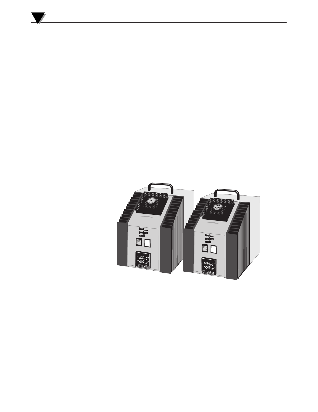
• The dual LED front panel display provides a clear view of both the block and
setpoint temperatures.
• You can easily set any temperature within the unit’s operating range using the
front keypad.
• A precision platinum RTD sensor controls the calibrator’s block temperature.
• The calibrator’s over-temperature multiple fault protection devices ensure both
user and instrument safety and protection.
To take full advantage of the calibrator’s many features, be sure to read the
operating procedures in Section 5 of this manual.
1.2 Technical Overview
• The hot point Calibrator features an aluminum-bronze block, which is
uniformly heated by four strategically located heaters.
• A powerful microprocessor-based digital PID auto-tune temperature controller
regulates the temperature.
• The calibrator is ready for use; optimum control parameters have been factory
programmed into the temperature controlling device. However, if you wish
to fine tune the calibrator for a particular operation, you may auto-tune the
PID parameters. Refer to Section 6, Changing the Controller Parameter.
1
Page 8
1
®
C
AL
IBRA
TIO
N CELL
CL900
CL950
®
C
ALIBRA
TION CELL
CL900 and CL950 hot point®Calibrators
1.2.1 CL900
The CL900 has a 6" deep test well that accepts a variety of optional inserts. These
inserts are sized to provide the best thermal contact with the test probe.
• The CL900 is shipped with an insert having a
• Optional inserts are available with 4" and 6" depths, for
probe diameters (see Section 10.2 for part numbers).
• An undrilled insert is also available, which can be drilled to the required well
diameter.
Order additional inserts separately as required for other diameter probes. For all
probes over 7" long, 6" depth wells are the best choice. See Section 10.2 for part
numbers.
1.2.2 CL950
The CL950 has a 6" deep built-in test well which accommodates 1⁄16", 1⁄8", 3⁄16", and
1
two,
⁄4" temperature probes. The multiport design allows you to:
• Calibrate more than one probe at a time.
• Use a pre-calibrated (or NIST traceable) probe and meter as a standard while
calibrating other probes.
1
⁄4" diameter well that is 6" deep.
1
⁄8", 3⁄16", 1⁄4", 5⁄16", and 3⁄8"
2
Figure 1-1. CL900 & CL950 hot point®Calibrators
Page 9

Section 2 - Unpacking
Remove the Packing List and verify that you have received all equipment. If you
have any questions about the shipment, please call the OMEGA Customer Service
Department at 1-800-622-2378 or 203-359-1660. We can be reached on the internet
at omega.com; e-mail: customerservice@omega.com
When you receive the shipment, inspect the container and equipment for any
signs of damage. Note any evidence of rough handling in transit. Immediately
report any damage to the shipping agent.
NO
The carrier will not honor any claims unless all shipping material is saved
for their examination. After examining and removing contents, save packing
material and carton in the event reshipment is necessary.
Check the shipping box to be sure you have received the following items:
CL900 CL950
CL900-110 or CL900-220 Calibrator CL950 Calibrator
CL906 Insert
1
⁄4" diameter x 6" depth well) Magnetized Reference Card
(
Insert Block Tongs Operator's Manual
Magnetized Reference Card
Operator’s Manual
CL900 and CL950 hot point®Calibrators
NOTE:
2
Section 3 - Safety
WARNING:
• NEVER touch the heated calibrator or probes without
proper protection.
• NEVER place any object (other than the CL900 insert)
into the CL900 block.
• NEVER use a voltage other than that for which your
unit is rated.
Use on a 50/60 Hz grounded outlet.
• NEVER replace either of the fuses with one of a current
rating greater than the original.
• NEVER unplug the heated calibrator until it has cooled
down to under 149°C (300°F).
• NEVER set objects on top of the calibrator.
CAUTION:
• DO NOT use the calibrator in excessively dusty or dirty
environments or near liquids.
• DO NOT attempt to alter the programmed constants (other
than the PID parameters discussed in Section 6).
• DO NOT turn off the power switch until the heated
calibrator has cooled down to under 149°C
(300°F).
3
Page 10
3
BENCH
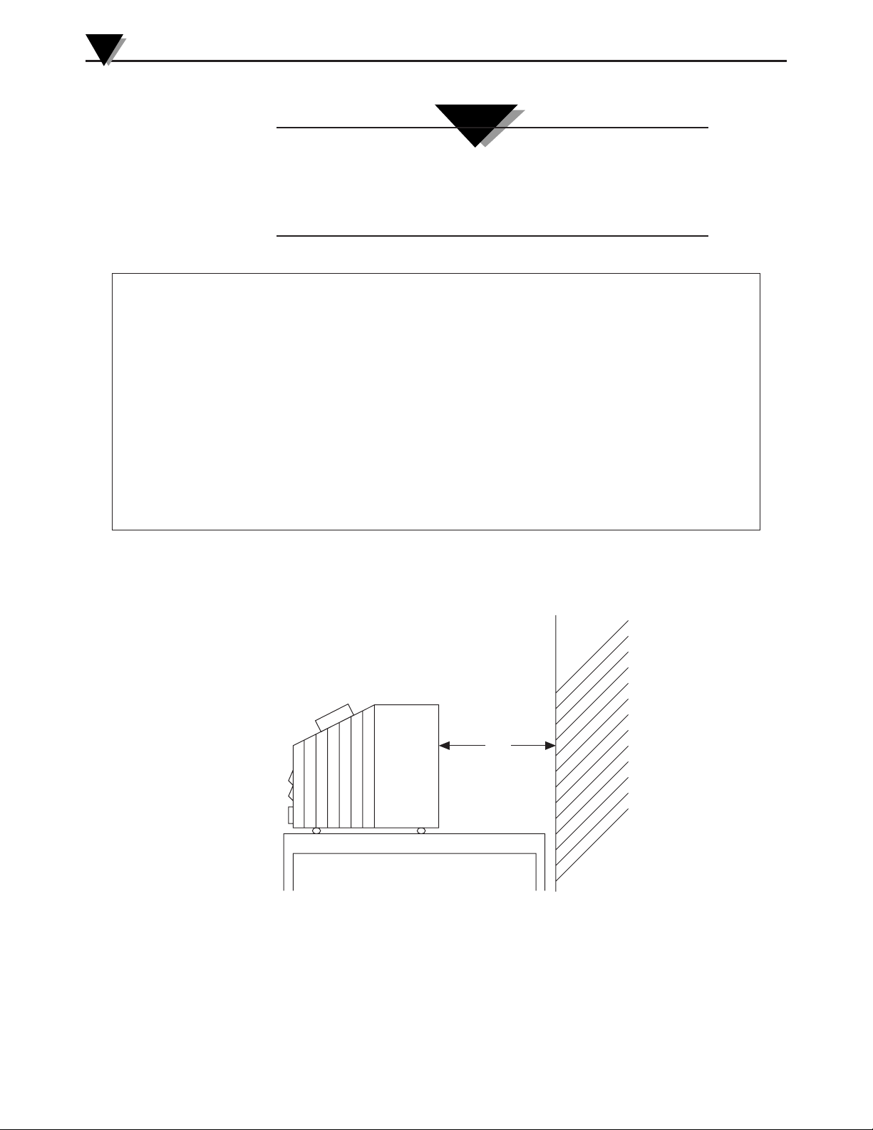
230 mm
(9")
MINIMUM
SIDE VIEW WALL
COOL-DOWN PROCEDURE
• KEEP THE CL900 PLUGGED IN WITH THE POWER SWITCH ON DURING COOL-DOWN,
SO THAT THE COOLING FAN WILL OPERATE CONTINUOUSLY.
1. Change the setpoint to 149°C (300°F) or lower, and allow the unit to cool down to
this temperature. When the CL900 has been operating in the 427°C to 482°C
(800°F to 900°F) range, it will take approximately one hour and 15 minutes to cool
down to 149°C (300°F).
2. You may unplug the unit without causing damage when it reaches 149°C (300°F).
If you turn off the power switch before reaching 149°C (300°F), the cooling fan
will still operate intermittently. This allows the unit to cool down safely. However,
when the CL900 has been operating at 482°C (900°F) and the power switch is
turned off, cooling down to 149°C (300°F) can take as long as two hours.
• DO NOT UNPLUG THE CL900 WITH THE TEMPERATURE ABOVE 149°C (300°F) OR
SEVERE DAMAGE MAY OCCUR.
CL900 and CL950 hot point®Calibrators
CAUTION:
• ALWAYS use the special tongs provided with the CL900 to
remove the insert.
• ALWAYS follow the proper procedure for cooling down the
calibrator (below).
• Operate the calibrator at ambient temperatures between 5°C and 38°C (40°F and 100°F).
• Leave at least 230 mm (9") of space between the rear of the calibrator and nearby objects
for air circulation. Keep the area around the instrument neat and clean. Position the
calibrator as shown in Figure 3-1.
4
Figure 3-1. Bench Top Position of the hot point®Calibrator
Page 11

CL900 and CL950 hot point®Calibrators
3
• The calibrator is a precision instrument. Although it has been designed for
optimum durability and trouble-free operation, it must be handled with
care.
• The calibrator generates very high temperatures. Probes can be very hot when
removed from the well. Take precautions to prevent personal injury or
damage to objects in the area.
• Allow the block to cool before exchanging CL900 inserts (see Section 7). Use the
special tongs that are supplied with the CL900 to remove the insert. Never
place anything (other than one of the CL900 inserts) into the CL900 block.
• Keep the calibrator connected to a live power source during the cooling period.
If the power switch is turned off while the calibrator is still warm, the
thermal sensor will automatically activate the cooling fan to insure a proper
cool-down. DO NOT unplug the calibrator while it is still above 149°C
(300°F); this may cause irreversible damage to the unit.
• The calibrator is equipped with two fuses, the fan fuse and load fuse.
- If either fuse should blow, first replace the defective fuse. Never replace
either of the fuses with one of a current rating greater than the original.
- If the fuse blows repeatedly, there is probably a problem with a component
in the calibrator. In this case, contact the OMEGA Customer Service
Department. To replace either fuse, unplug the calibrator. If the unit is
hot, restore power to the fan as quickly as possible to prevent internal
damage. See Section 9.3 for more details.
• The hot point Calibrator is pre-programmed and factory calibrated for
optimum performance. Refer to Section 6 for changing the factory preset
parameters.
• The calibrator cannot be field-calibrated. If you suspect that the unit is out of
calibration or in need of repair, contact OMEGA for assistance. Do not
attempt to alter the programmed constants (other than the PID parameters
as discussed in Section 6).
• Two thermal sensors provide over-temperature protection for the hot point
Calibrator. These sensors are strategically located on the calibrator’s block
cooling jacket. If the temperature exceeds normal limits, these sensors turn
off power to the heaters. Both sensors reset automatically when operating
conditions return to normal.
5
Page 12

4
6
3
5
4
CL900
1
2
7
8
9
10
12
11
Back of Calibrator
6
3
CL950
1
2
7
CL900 and CL950 hot point®Calibrators
Section 4 - Parts of the Calibrators
6
Figure 4-1. CL900 & CL950 Calibrator Parts
Page 13

CL900 and CL950 hot point®Calibrators
KEY LABEL DESCRIPTION
1POWER SWITCH The switch has 2 positions labeled ON and OFF. Use ON for nor-
mal operation. OFF disconnects power to the entire unit with the
exception of the cooling fan circuit.
2 CYCLE INDICATING The lamp is located on the front panel of the calibrator to the right
LAMP of the power switch. The red pilot light indicates the turning "on" and
"off" of the heating cycle.
3 STABILIZING BLOCK Made from aluminum bronze, specifically designed to be heated
and controlled to precise preset temperatures. The stabilizing block
is located directly under the screen on the top sloped surface of the
calibrator. The stabilizing block allows various types and sizes of
temperature sensors to be inserted for calibration.The CL900 stabilizing block has removable inserts.
4 INSERT CL900 ONLY: Made from aluminum bronze in a cylindrical form.
Designed to be inserted into the stabilizing block through an open-
ing in the top of the calibrator. The insert has a hole at one end
(called the well) with a diameter and depth chosen to accept the
size of the sensor being calibrated. Refer to Figure 10-1 for the
types of inserts available.
5 INSERT BLOCK TONGS CL900 ONLY: Designed for gripping the top end of the insert (which
has two diagonally placed holes) to remove it from the stabilizing
block.
6 HEAT SINK Consists of a dual set of aluminum fins that thermally support the
discharge of excess heat from within the calibrator.
7 DISPLAY PANEL A microprocessor-based PID auto-tune dual display controller.
Refer to Figure 4-2 for additional information.
8FAN FUSE Controls the fan circuit only. The fuse has a fast blow, 3 A G, 1/8 A,
250 V rating.
9 LOAD FUSE Controls all circuitry with the exception of the fan circuit. The fuse
has a fast blow, 3 A G, 10 A, 250 V rating.
10 POWER CORD Use only the voltage for which your unit is rated. Use only a
50/60 Hz grounded outlet.
11 AUXILIARY JACK Reserved for future use
12 RS-232-PORT 9 pin sub d connector for RS-232 communications
TABLE 4-1
CALIBRATOR PARTS & ACCESSORIES
4
7
Page 14

400 SV
P. I. D. INDICAT O R
MENU
ACCESS
KEY
RAISE
KEY
LOWER
KEY
MODE/
ENTER
KEY
SETPOINT TEMPERATURE
PROCESS TEMPERATURE
400 PV
4
CL900 and CL950 hot point®Calibrators
Temperature Controller:
The temperature controller provides a separate digital display for setpoint
temperature as well as process temperature. Buttons are provided on the
front panel for configuring the controller. The CL900/CL950 is shipped preconfigured. The customer should not alter any parameters except for the
displayed engineering units (°C/°F).
Figure 4-2. CL900 & CL950 Controller Display
P.I.D. Indicator:
When this light is illuminated, the unit is heating up the target plate.
NOTE
:
P.I.D. Control: Proportional, integral, derivative control
( P.I.D.) is a temperature control algorithm used in highend temperature controllers. The controller causes the
process to attain the desired temperature by turning the
process on or off. The process may be a heater or
refrigerator. As the process temperature approaches the
setpoint temperature, the hot or cold process will be
pulsed to reduce the corrective measures and minimize
overshooting. The controller provides a visual
representation of the process status through LED
indicators. An indicator may light continuously, blink, or
shut off entirely to indicate that the process is on, being
pulsed, or off, respectively.
8
Hold down for 3 seconds, initially, to access the programming mode. Once
in the programming mode, momentarily press this key to scroll through the
menus.
Momentarily press to increase the selected parameter or scroll upward in
the list of possible settings.
Menu Access Key:
Raise Key:
Page 15

Lower Key:
Momentarily press to decrease the selected parameter or scroll downward in the
list of possible settings.
Mode/ Enter Key:
Hold down for 3 seconds, initially, to enter the standby setup mode. Once in the
program mode viewing a parameter, use this key to save the current setting and
advance to the next parameter.
Section 5 - Operating Procedures
CL900 and CL950 hot point®Calibrators
CAUTION: CAUTION
5
• Operate the calibrator at room temperatures between
5° and 38°C (40° and 100°F).
• Always use the calibrator in an area with adequate
ventilation, where the air can move freely around the unit.
• Allow ample clearance (at least 9" at the back of the
unit for the stabilizing and cooling air to exhaust).
• Do not place the calibrator near objects subject to
heat damage.
5.1 BEFORE turning the calibrator ON
1. Make sure that the power switch is in the OFF position.
2. Trial fit the temperature probe that you want to calibrate in the insert test well
to determine whether you have selected the right size. The probe should fit
snugly inside the test well for good thermal contact. In order to maintain
stated accuracies, the sensing portion of the test probe must make good contact
with the bottom of the test well.
2a. Use probes 5" or longer in the 4" test well, and probes 7" or longer in the 6"
test well. The additional probe length will:
• Ensure that the probe reaches the bottom of the well
• Protect any connectors, junctions, etc., from heat damage or thermal gradients
2b. For long probes, the calibration process is more accurate using the 6" test well.
3. Check to see that the insert is seated properly in the stabilizing block.
4. Determine whether you are going to test probes in °C or °F. Set the
temperature through the controller menu to °C or °F.
5. Connect the probe being calibrated to the readout device (meter, controller, etc.).
6. Make sure that the top screen of the calibrator is clear so that airflow will not
be restricted.
7. Plug the calibrator into a properly grounded outlet.
9
Page 16

5
CL900 and CL950 hot point®Calibrators
5.2 Using the Calibrator
1. Check to be sure you have completed the steps in Section 5.1.
2. Turn the calibrator ON. You will hear the fan operating.
3. Select the desired temperature setpoint on the calibrator display.
3a. Use the or key on the front of the display to enter the new
temperature setpoint value. The unit will begin heating the calibrating block
to the temperature set on the setpoint display. See set @ 38°C (100°F)
3b. The setpoint variable will change at 3 different rates, depending on how long
a key is being pushed. The minimum setpoint is 38°C (100°F), the maximum
setpoint is 482°C (900°F).
4. For best results, wait approximately 15 minutes after the calibration block
reaches the setpoint to allow the internal temperature of the calibrator to
stabilize.
4a. The setpoint temperature appears on the green display.
4b. The actual temperature of the well appears on the red display.
4c. The temperature indicated on the red temperature display is your reference
temperature for calibration.
5. You are now ready to calibrate your probes.To determine probe accuracy,
compare the reference temperature displayed by the calibrator (red display)
with that shown on the probe readout device.
CAUTION:
Handle hot probes carefully.
OPERATING TIPS
• When using the CL900 to test more than one probe, group all the probes that
require the same insert size (i.e., all
1
⁄8" diameter probes together, all 3⁄16" diameter
probes together, etc.). Otherwise, you must wait for the calibrator to cool, change
the insert, then reheat the calibrator for the next probe.
• When calibrating probes at several setpoints, start at the lowest temperature
and work up to higher temperatures. Do not jump back and forth between a
very high temperature setting and a relatively cool setting. This will eliminate
waiting time for the calibrator to cool down and re-stabilize.
• Allow time for the temperature to stabilize before proceeding with calibration.
6. After calibrating each probe, remove it from the test well and place it in a safe
area for cooling. If you have another probe to test, insert it in the test well, set
the setpoint on the calibrator display panel, and wait for the temperature to
stabilize (see Steps 3 and 4). Compare the reference temperature on the
calibrator with the temperature of the probe being calibrated. Repeat for each
subsequent probe.
10
7. COOL-DOWN PROCEDURE: After you have calibrated the last probe, adjust
the setpoint value to 149°C (300°F) or lower and press the ENT key (see Step3).
After the calibrator has cooled down to this temperature, turn off the power
switch and unplug the unit (if necessary).
Page 17

CL900 and CL950 hot point®Calibrators
Menu 00 Menu 01 Menu 02 Menu 03 Menu 04 Menu 05
Key Lock SETPOINT Ac.Cd = 02 Ac.Cd = 03 Ac.Cd = 04 Ac.Cd = 05
Ac.Cd
Gn.o1 113 ALr1 925 id.no 01 SnSr P
Gr.o2 ALr2 bAUd 12.o.7 Sn.00
rAtE 24 Cy.t1 01 CAL.L dEC.P
rSEt 122 Cy.t2 CAL.H FILt
H.Hys SP.tt OFF OUt.1 Ht.P
HyS.1 L.SP.L 80 OUt.2 ALR
C.HyS L.SCL CoL.t nor
HyS.2 U.SP.L 900 A1.HL HI
C.SPr H.SCL A1.Pd Pr
SPr.2 A1.OP LAt
dPnG Nl A2.HL Hl
A2.Pd Pr
A2.OP OFF
Unit F
Section 6 - Changing the Controller Parameter
The CL900/CL950 operates at its optimum performance when left with the
factory parameter settings. The only internal parameter that most operators may
need to change is the engineering units (°C or °F). Below are two diagrams: a)
menu hierarchy with factory default settings, b) programming procedure. In the
event that some parameters have accidentally been changed, use the factory
default settings shown below.
NOTE:
Changing any parameter settings other than the engineering
units will decrease the accuracy of your calibrator.
6
Figure 6-1. Controller Menu Hierarchy Showing Factory Default Parameter Settings
WARNING:
Do not re-program the controller’s parameter settings or
change the wiring inside your unit to override the maximum
setpoint value of 482°C (900°F).
Changing the controller’s parameter settings:
1. Press the key to enter the programming mode. The lower display will
alternately display the menu level and “Ac.Cd.”
2. Use the and keys to change to the desired menu level.
3. Once you have chosen the desired menu use the key to scroll through the
parameters. To change the setting of a given parameter, use the and keys.
4. To save settings press the key. The controller now exits the programming
menu and returns to the normal operating mode.
5. To change settings on other menu levels, you must re-enter the programming
menu (from step #1).
Figure 6-2. Programming Procedure
11
Page 18

7
CL900 and CL950 hot point®Calibrators
Section 7 - Interchangeable Test Inserts
The CL900 calibrator accepts a variety of standard and metric optional inserts,
which are available in 4" and 6" depths, and for probe diameters from
An undrilled insert is also available for non-standard hole sizes.
7.1 Changing the Insert (CL900 only)
To change the insert:
1. Allow the calibrator to cool to room temperature. See Section 3 for the cooldown procedure.
2. Place the tong points in the two holes and lift the insert out of the stabilizing
block.
3. Put a new insert in the block, making sure it touches the bottom.
4. Reheat the insert to the desired temperature (see Section 5).
7.2 Solid Insert Drilling Information (CL911 only)
Have a qualified machinist drill the insert to the desired hole diameter with the
correct tolerance and depth. The hole diameter should allow the test probe to be
readily inserted with the minimum amount of clearance at
1
⁄64".
1
⁄8" to 3⁄8".
12
Page 19

CL900 and CL950 hot point®Calibrators
1
6789
6789
234 5
12 34 5
RX
TX
GND
TX
RX
GND
Section 8 - RS232 Communication
This method allows bi-directional data transfer via a three-conductor cable
consisting of signal ground, receive input, and transmit output. It is
recommended that less than 15.2 meters (50 feet) of cable be used between the
computer and this instrument. Note that multiple instruments cannot be tied to
the same port in this configuration. The RS232 port is optically isolated to
eliminate ground loop problems.
Below is a pinout diagram for the serial port of the CL900/CL950 as well as the
pinout for a 9-pin PC serial port. Use a straight DB9(female) to DB9(male)
connector cable to connect your computer to the CL900. The cable should be
attached only when the computer and CL900 are off.
Only parameters in the parameter list should be modified or queried via the
serial port. Other parameters should be viewed or querieddirectly from the
controller. It is highly recommended that baud rate for the controller be modified
on the controller directly. Note that both the CL900 and the computer must be
communicating with the same serial communications parameters to establish a
working communications link.
8
The serial communications feature can be tested using terminal emulation
package. Note that this controller does not time-out waiting for the next
character to be transmitted. Be sure not to use XON/XOFF or hardware
handshaking. Lastly, it should be noted that following a complete transmission
to the CL900, a response is sent back. If the message was valid, the changed or
queried parameter is echoed back (following the same format). If the message
was not according to acceptable format or was attempting to force a parameter
out of range, an "ERROR" message is echoed.
Note, only RS232 protocol is supported by the serial port. Voltage levels are not
to exceed ±12 Vdc. A standard 9-wire cable should be used, with shielding and
DB9 connectors. The CL900/CL950 connections are female. Most computers
have a 9-pin male connection. Hence, a male-female cable with straight-through
connections is appropriate for interfacing.
Figure 8-1. Connecting the CL900 to a Computer’s Serial Port
13
Page 20

8
CL900 and CL950 hot point®Calibrators
Parameter List (only relevant parameters shown):
PAR#: Parameter: Range/ Units:
00 Process Temp. Input determined
01 Setpoint Input determined
19 Baud Selection bAUd
Baud Selections:
Code: Baud: Parity: Data Bits: Stop Bits:
3.o.7 300 odd 72
6.o.7 600 odd 72
12.o.7 1200 odd 7 2 (factory default settings)
24.o.7 1200 odd 72
3.n.8 300 no 81
6.n.8 600 no 81
12.n.8 1200 no 81
24.n.8 2400 no 81
General Message Format:
#[controller id][command][parameter number]<new value><units>[CR/LF]
Definitions:
1
# - This character initiates an "escape sequence" that the controller will recognize.
N
[controller id] – Up to 2 numeric characters, ‘00’ to ‘99’ (factory default = ‘01’).
[command] – 1 character, upper case or lower case.
‘R’ – To read a parameter from the controller.
‘M’ – To temporarily modify a controller parameter (lost upon shutdown)
‘E’ – To modify a controller parameter in non-volatile memory (saved even
after shutdown).
[parameter #] – Up to 2 numeric characters, ‘00’ to ‘99’.
<new value> - This control word is used only when entering or modifying a
parameter.
1
N
Up to 6 characters may be entered. The first character can be a space, a ‘+’, or
a ‘-’. The next 4 characters are for entering the new parameter value. Be sure to
use the exact same field format as is currently being used. (i.e, if the XXX.X
format is used to express temperature, be sure to enter a new value that
conforms to the same format).
<units> - This optional control word is used to specify units, C for °C, F for °F.
1
N
[CR/LF] – Every transmission must be terminated with a carriage return [CR]
character. The line feed [LF] character is optional.
14
Page 21

Section 9 - Maintenance
9.1 Calibration
This unit has been fine tuned at the factory and calibrated to give optimum
performance at its full temperature range. It is recommended that the unit be
returned annually for re-calibration.
9.2 Cleaning
Remove all electrical connections and power before
attempting any maintenance or cleaning.
9.2.1 Main Body
Only a damp soft rag with a mild cleaning solution should be used when
cleaning the main body of this unit.
CL900 and CL950 hot point®Calibrators
CAUTION:
9
9.2.2 Probe Well
Send the unit back to OMEGA in the event that the probe well becomes dirty. Do
not attempt to remove the probe well from the unit.
9.2.3 Fan and Vent Guards
The fan guard and vent guards should be cleaned annually. A medium-power
vacuum cleaner with a brush attachment is recommended.
9.3 Fuse replacement
Disconnect power cord from source before replacing
fuse.
For continued protection against the risk of fire, replace with
only the same size, type, and rating fuse indicated here and
on the rear panel of your unit.
WARNING:
CAUTION:
The fuse for the fan is a 3AG fast blow type with a 1/8A, 250V rating. The main
load fuse is a 3AG fast blow type with a 10A, 250V rating. Usually a blown fuse
indicates a defective component within the calibrator. Try replacing the fuse first;
if it blows repeatedly, there probably is a defective component. Call OMEGA for
instructions.
15
Page 22

9
CL900 and CL950 hot point®Calibrators
1. Turn off the calibrator and unplug it from the wall outlet.
2. Unscrew the fuse cap and remove the blown fuse.
3 Insert a new fuse of the same type and current rating, then replace the fuse
cap.
4. Plug the calibrator into the wall outlet.
5. Turn the calibrator ON using the ON/OFF switch.
CAUTION:
If the unit is very hot, restore power to the cooling fan as soon
as possible. Otherwise, serious internal damage to the
calibrator may occur.
16
Page 23

CL900 and CL950 hot point®Calibrators
Section 10 - Troubleshooting Guide
10.1 Troubleshooting Problems and Solutions
Problem Solution
1. Unit will not turn on. a. Check all electrical connections.
2. Unit turns on but the probe a. Check that you have entered a setpoint
well will not get hot. above the ambient temperature.
10
b. Check rear panel fuses.
c. Unit may require service. If problem
persists, contact our customer service
department.
b. Verify that the controller is set to its
factory default settings.
c. Unit may require service. If problem
persists, contact our customer service
department.
d. Unit may have been operated above
ambient temperature operating range
and safety cutoff switch has disabled
heater. In that case, unit should be sent
back to factory for reset and safety check.
3. Controller display shows “Err.H” a. Unit requires service. Contact our
and the probe well will not get hot. customer service department.
4. Probe well temperature will not a. Verify that the controller parameters
stabilize to within ±0.5° of the are set to factory default settings.
setpoint temperature.
b. Line voltage is not stable.
c. Unit may requires service. Contact our
customer service department.
17
Page 24

10
DESCRIPTION PART NUMBER
Back Plate HP-0014
Barrier Terminal Strip HP-0020
Control Module HP-0022
End Plate for Heater Block HP-0003
FAN FOR 110 Va c OPERATION HP-0023 *
Front Panel with Cutouts HP-0004
Fuse Holder 200-91
FUSE, 10A, GLASS, LOAD HP-0034
FUSE, 1/8A, GLASS, FAN HP-0033
Grommet HP-0028A
Handle DIP-0029
Heater, 7", 250W HP-0024
Heatsink, Left HP-0006
Heatsink, RightHP-0007
Inner Heater CaseHP-0008
Inner Heater Case End Cover HP-0018
INSERTS (CL900 only) SEE SECTION 9.4.3
Insert Guide HP-0005
Intake Screen Bottom HP-0026
Insulating Ring, Nylon 200-0004
Jack, 3 conductor HP-0041
Label, Top Front Case HP-0011
Label, Bottom Front Case HP-0010
Label, Caution L-1103
Label, 1/8A L-1104
Label, 10A L-1102
Lockwasher, #8 Heavy SEL-0023
Lockwasher, #10 Heavy HP-0035
Magnetic Strip HP-0036
Nut, #10-32, Hex HS-0260S
Nut, #8-32, Hex DIP-0068/01
Strain Relief DIP-0046
Outer Heater Case Bottom HP-0013
Outer Heater Case Cover HP-0012
Plug, Jack HP-0040
POWER CORD, 9 FT, 16AWG DIP-0045A
Rear Enclosure HP-0015
Rear Exhaust Screen HP-0029
REFERENCE CARD MCD-0104
RTD Element HP-0019
Rubber Feet DIP-0026
* This item has a dif ferent part number in 220 Vac units.
Refer to Section 9.4.2.
CL900 and CL950 hot point®Calibrators
10.2 Spare Parts
10.2.1 115 VAC PARTS LIST
TABLE 10-1
Components that are more likely to need replacement are shown in BOLD type.
18
Page 25

DESCRIPTION PART NUMBER
Fan for 220 V
Panel Lamp for 230 Vac
ac operation HP-0023A
Switch, Rocker, ON/OFF, DPST,
for 230 Vac
DIP-0054A
DIP-0148
DESCRIPTION PART NUMBER
Screw, #10-32 x 1" Long, Socket Cap HS-0192S
Screw, #6 x 1/4" Long, Self Tap, Pan DIP-0067S
Screw, #6 x 3/8", Type F DIP-0072
Screw, #6 x 1/2" Long, Self Tap, Black DIP-0067
Screw, #8-32 x 1/2" Long, Socket Cap HS-0183S
Screw, #8-32 x 1/4" Long, Fillister Head HS-0102
Screw, #8-32 x 3/8" Long, Fillister Head HS-0339
Screw, #8-32 x 5/16" Long, Black Oxide HS-0269
Screw, #8-32 x 1/2" Long, Pan Head DIP-0065
Shield for Fan HP-0031
Socket Head, #8-32 x 1/4" Long HS-0370S
Solid State Relay HP-0021
Spacer for Fan HP-0030
Standoff, #8-32 through 1" HP-0032
Stabilizing Block (CL900) HP-0017
Stabilizing Block (CL950) HP0046
Stabilizing Block Metal Shield HP-0016
Stud, #8-32 x 3/8" Long RPI-0011
Switch, Rocker, ON/OFF, DPST, 20 A DIP-0054*
for 115 Vac
Panel Lamp for 115VAC DIP-0043
THERMAL SWITCH (above fan) HP-0025
Thermal Switch HP-0027
* This item has a different part number in 230 Vac units.
CL900 and CL950 hot point®Calibrators
115 VAC PARTS LIST (continued)
Components that are more likely to need replacement are shown in BOLD type.
10
10.2.2 230 VAC PARTS LIST
The following three components are unique to 230 Vac units.
TABLE 10-2
19
Page 26

10
CL900 and CL950 hot point®Calibrators
10.2.3 PROBE WELL INSERTS FOR THE CL900
Probe Well Inserts with "Inch Sizes" Probe Well Inserts with "Metric Sizes"
OMEGA Probe Hole Probe Hole OMEGA Probe Hole Probe Hole
Part No. Diameter Depth Part No. Diameter Depth
CL901 1/8" 4" CL901-M 2 mm 101.6 mm
CL902 1/8" 6" CL902-M 2 mm 152.4 mm
CL903 3/16" 4" CL903-M 3 mm 101.6 mm
CL904 3/16" 6" CL904-M 3 mm 152.4 mm
CL905 1/4" 4" CL905-M 4.5 mm 101.6 mm
CL906 1/4" 6" CL906-M 4.5 mm 152.4 mm
CL907 5/16" 4" CL907-M 6 mm 101.6 mm
CL908 5/16" 6" CL908-M 6 mm 152.4 mm
CL909 3/8" 4" --CL910 3/8" 6" --CL911 UNDRILLED 6" Max. ---
TABLE 10-3
20
Page 27

CL900 and CL950 hot point®Calibrators
Section 11 - Specifications
All specifications assume that the test probe is in contact with
the bottom of the well. See Section 5.1, Step 2a, for probe
length recommendations.
11.1 CONTROL PANEL
DISPLAY
PROCESS VALUE DISPLAY: Digital LED, red
SETPOINT DISPLAY: Digital LED, green
PARAMETER DISPLAY: Setpoint, Control Output, Proportional Band,
11
NOTE:
Integral Time, Derivative Time, High/Low Alarm
Limit, Cycle Time, Alarm Sensitivity, Sensor
Compensation, Lower/Upper Setting Limit
STATUS DISPLAY: Auto-Tuning, High/Low Alarm, Control Output
SETPOINT SETTING
SETTING METHOD: Front membrane keypad
SETPOINT SELECTION: Parameter check, UP, DOWN, AUTO-TUNE, ENT,
MODE KEY
SENSOR TYPE: RTD, Pt, 100Ω (alpha = 0.00385)
11.2 CALIBRATOR
TEMPERATURE RANGE: Low: Ambient +22°C (Ambient +40°F)
High: 482°C (900°F)
OPERATING AMBIENT
TEMPERATURE: 5°C to 38°C (40°F to 100°F)
ACCURACY: CL900: 101.6 mm (4") test well:
±3°F ±1 LSD of displayed resolution
152.4 mm (6") test well:
±1.5°F ±1 LSD of displayed value
CL950: ±1.5°F ±1 LSD of displayed value
CONTROL STABILITY: ±0.3°F or better
21
Page 28

11
DIMENSIONS mm (in)
216 mm
(8-1/2")
300 mm
(11-3/4")
311 mm
(12-1/4")
CL900 and CL950 hot point®Calibrators
11.2 CALIBRATOR continued
TEMPERATURE CL900: 4" test well: ±0.4%, within 2 to 25.4 mm
UNIFORMITY: (0 to 1") from the bottom of the test well
MAXIMUM PROBE CL900: 100 mm test well inserts: 101.6 mm (4")
INSERTION: 150 mm test well inserts: 152.4 mm (6")
INSERT WELL INSIDE 1/8", 3/16", 1/4", 5/16", 3/8", and nominal undrilled insert
DIAMETERS (CL900):
POWER REQUIREMENTS: Standard: 115 Vac, 50/60 Hz, 1.05 kW
6" test well: ±0.3%, within 2 to 25.4 mm
(0 to 1") from the bottom of the test well
CL950: ±0.3%, within 2 to 25.4 mm (0 to 1") from
the bottom of the test well
CL950: 150 mm (6")
Optional: 230 Vac, 50/60 Hz, 1.05 kW
WEIGHT: 10.1 kg (22.3 lb)
DIMENSIONS: Refer to Figure 11-1.
22
Figure 11-1. CL900 & CL950 Overall Dimensions
Page 29

Section 12 - Schematic
CL900 and CL950 hot point®Calibrators
12
Figure 12-1. CL900 & CL950 (110V) Schematic
23
Page 30

12
CL900 and CL950 hot point®Calibrators
24
Figure 12-2. CL900 & CL950 (220V) Schematic
Page 31

SECTION 1 - INTRODUCTION
ON
®
THERMOCOUPLES
OMEGA’s TRCIII ice point™ Reference Cell relies on the equilibrium of ice and
distilled, deionized water at atmospheric pressure to maintain six reference wells
at precisely 0°C. The well extends into a sealed cylindrical chamber (containing
the distilled, deionized water) whose outer walls are cooled by thermo-electric
cooling elements. The increase in volume produced by the creation of ice crystals
within the Reference Cell is sensed by the expansion of a bellows that operates a
microswitch and controls the cooling elements. The alternate freezing and
thawing of the ice accurately maintains a 0°C environment around the reference
wells. The ice point Reference Cell is available in two models: 115 Vac model
(part number: TRCIII) as well as the 220 Vac model (part number: TRCIII-220).
Protect the TRCIII from freezing conditions (including during
shipping). Damage will result if the unit is stored below
40°F.
TRCIII ice point™Reference Cell
CAUTION:
1
Main features of the ice point Reference Cell:
• Provides a highly accurate 0°C thermo-electric "refrigerator"
• Eliminates old-fashioned "ice bath"
• Supports versatile uses in the factory, laboratory, or instrument shop
• Calibrates all temperature instruments and temperature sensors
• Includes rugged outer case for safe portability
• Accepts up to 6 probes
Figure 1-1. TRCIII ice pointTMReference Cell
25
Page 32

2
TRCIII ice point™Reference Cell
Section 2 - Unpacking
Remove the Packing List and verify that you have received all equipment. If you have any questions
about the shipment, please call the OMEGA Customer Service Department at 1-800-622-2378 or 203-
359-1660. We can be reached on the internet at omega.com, e-mail: customerservice@omega.com
Upon receipt of shipment, inspect the container and equipment for any signs of
damage. Take particular note of any evidence of rough handling in transit.
Immediately report any damage to the shipping agent.
NOTE:
The carrier will not honor any claims unless all shipping
material is saved for their examination. After examining and
removing contents, save packing material and carton in the
event reshipment is necessary.
Make sure the following are packed in the shipping box.
• TRCIII ice point Reference Cell
• Bottle of mineral oil (approximately 1 ounce)
• Operator’s manual
Section 3 - Safety
Operate the ice point Reference Cell in ambient temperatures between 2°C and
32°C (35°F and 90°F). Allow sufficient air circulation by leaving a minimum of
50.8 mm (2") of space between the rear of the ice point Reference Cell and nearby
objects. The thermo-electric cooling modules rely on free air convection over the
two finned heat sinks. Refer to Figure 3-1.
26
Figure 3-1. Bench Top Position of the ice pointTMReference Cell
Page 33

TRCIII ice point™Reference Cell
Section 4 - Parts of the ice pointTMReference Cell
• On the top of the TRCIII is a handle for easy transportability.
• On the sloping front surface of the unit is the power switch and the power
indicator light.
• Below the power switch and light are 6 reference wells (4 .0 mm [5/32"] ID
holes) where up to 6 thermocouple probes can fit in to be tested. Refer to
Figure 4-1. These reference wells extend into a sealed cylindrical cell
containing distilled, deionized water. The Reference Cell wall is cooled by
thermo-electric modules. When ice is formed within the Reference Cell, an
increase in volume is sensed by the expansion of a bellows. This bellows
actuates a microswitch which turns off power to the modules. As the ice
within the Reference Cell begins to melt, the bellows contracts. This activates
the microswitch, that in turn energizes the cooling modules. The microswitch
actuator is factory-adjusted to maintain sufficient ice within the Reference Cell
to maintain a well temperature within 0°C ± 0.1°C. The sensitivity of the
bellows mechanism is such that the amount of formation and melting of ice
will provide stability to within ± 0.04°C.
4
Figure 4-1. Internal View of the ice pointTMReference Cell
27
Page 34

5
TRCIII ice point™Reference Cell
Section 5 - Operating Procedures
1. Place the ice point Reference Cell to allow a 50.8 mm (2") minimum of free air
space on all sides. The thermo-electric cooling modules rely on free air
convection over the two finned heat sinks. No fan is required. The rear section
of the unit contains the power supply. Convective air cooling is provided
through a perforated panel on the bottom and a louver on each side near the
top of this section. Additional cooling is supplied by a perforated sheet metal
enclosure between the rear section, which contains the power supply, and the
heat sink section, which houses the Reference Cell.
2. Plug in the unit and turn on the power switch. The red pilot light on the front panel
will illuminate (showing that power has been applied and cooling has begun).
3. After 2 to 3 hours, depending on ambient air temperature, the pilot light will
begin to cycle. This cycle period may vary 30 seconds to 2 minutes. At this
time, the equilibrium of the Reference Cell is reached and the unit may be
placed in service.
4. Add 3 to 4 drops of mineral oil or other heat-transfer fluid to each of the 6
reference wells. Place reference thermocouples into the wells, making sure that
the junctions are at the bottom of the reference wells.
5. The thermocouple wells are internally grounded to earth through the 3-wire
power cord. However, if the wells need to be grounded to an external system
so as to minimize electrical noise pickup, a standard adaptor plug may be used
on the power cord plug. The ground wire from the adaptor plug should be
connected to the external system ground.
Section 6 - Thermal “Loading” of the ice pointTMReference Cell
The thermocouple wire, which is inserted into the unit’s reference well, will
conduct some heat into the reference area. Obviously, if more thermocouples are
placed in a well and the unit is working in a high-temperature ambient
environment, more heat will be conducted into that well. The reference
temperature may be affected if too great a "thermal load" (i.e., too many
thermocouples) is placed on any given reference well. The unit is designed to
remain within the published specifications when all 6 wells are fully loaded with
6 OMEGA TRP probes. For accessory probes, refer to Section 9.
Section 7 - Application Notes
The ice point Reference Cell provides a precise 0°C temperature environment for
thermocouple reference junctions, RTD (Resistance Temperature Detector)
calibration, or any application requiring an accurate, stable reference temperature.
28
Example 1: Thermocouple Reference Junctions
The most common ice point Reference Cell application is for use in referencing
thermocouples. A thermal EMF is generated at any junction of dissimilar metals.
To avoid generating an EMF at the terminals of readout instruments or terminal
blocks, it is common practice to "reference" the thermocouple wire as shown in
Figure 7-1. Thermocouple wire is joined to copper lead wire by welding or
mechanical procedures.
Page 35

TRCIII ice point™Reference Cell
8
The junctions are maintained at exactly 0°C in the wells. The copper lead wire
is connected to the readout device (which normally has copper terminals and
wiring). Standard thermocouple calibration tables are compiled on the basis of
this arrangement; therefore, temperatures may be read directly from standard
tables. Tables may be obtained from OMEGA Engineering.
Figure 7-1. Common Thermocouple Reference Hookup
Example 2:
The ice point Reference Cell may also be used for calibrating temperature sensing
devices such as RTDs, thermistors, or standard mercury or alcohol thermometers.
To accomplish this, simply insert the device into one of the reference wells. The
reference temperature is exactly the freezing point of water.
Section 8 - Troubleshooting
The ice point Reference Cell has been designed for years of continuous,
trouble-free operation. No periodic maintenance is required.
However, in case the unit fails to operate at any time, check the following items:
• Was the unit frozen or exposed to freezing temperatures during shipment or
storage? If so, the Reference Cell may be damaged and will require factory
repair.
• Is the fuse good? The fuse is located on the back panel of the unit.
Replacement fuse size is 8AG, 2 amp.
• The microswitch may need adjustment. However, before any visual or
mechanical checking can be done, the ice point Reference Cell must be shut off
for a period of about 4 hours or until the well temperature has reached ambient
temperature. Then, locate the small hole plug on the rear panel. It must be
removed to make any adjustment. The adjustment screw can be reached by
inserting a blade-type screwdriver with a shaft length of at least 69.9 mm (2
After turning the ice point on again, note if the pilot light is on or off.
If the pilot light is ON, make the following adjustments:
1. Turn screw clockwise until the lamp turns OFF.
2. Turn screw counter-clockwise until the lamp comes ON.
3
⁄4).
3. Continue making 6 complete turns. Adjustment is then complete.
CAUTION:
If the pilot light remains lit during this adjustment
procedure, the ice point Reference Cell MUST be
returned to OMEGA for repair.
29
Page 36

9
TRCIII ice point™Reference Cell
If the pilot light is OFF, make the following adjustments:
1. Turn screw counter-clockwise until the pilot light comes ON.
2. Continue making 6 complete turns. Adjustment is then complete.
If none of the above procedures correct the condition, contact the OMEGA
Customer Service Department for help and directions on returning your
TRCIII ice point Reference Cell.
Section 9 - ACCESSORIES
The following Temperature Reference Probes (TRP) may be ordered for use with
the ice point Reference Cell:
PART NUMBER THERMOCOUPLE TYPE
TRP-K K CHROMEGA®-ALOMEGA
TRP-J J Iron - Constantan
TRP-E E CHROMEGA®- Constantan
TRP-T T Copper - Constantan
TRP-S S Pt10%Rh - Pt
TRP-R R Pt13%Rh - Pt
TRP-B B Pt30%Rh - Pt6%Rh
TRP-G G W - W26%Re
TRP-C C W5%Re - W26%Re
TRP-D D W3%Re - W25%Re
Section 10 - SPECIFICATIONS
Reference Temperature: 0°C
Accuracy: 0°C ± 0.1°C or better
Stability: ± 0.04°C for constant ambient stability
Ambient Temperature 2°C to 32°C (35°F to 90°F)
Range:
Reference Well: 6 wells, 4.0 mm (
®
5
⁄32") ID, 95.3 mm (3-3⁄4") deep.
Wells are thermally and electrically grounded to
each other.
30
Power Required: 115V, 60 Hz, 100 watts (220V also available)
Stabilization Time: 2 or 3 hours depending on ambient
temperature and thermal load
Weight: 9.2 kilograms (21 pounds)
Dimensions: Refer to Figure 10-1.
Page 37

TRCIII ice point™Reference Cell
10
Figure 10-1. Overall Dimensions
31
Page 38

TRCIII ice point™Reference Cell
NOTES:
32
Page 39

WARRANTY/DISCLAIMER
OMEGA ENGINEERING, INC. warrants this unit to be free of defects in materials and workmanship for a
period of 13 months from date of purchase. OMEGA’s WARRANTY adds an additional one (1) month
grace period to the normal one (1) year product warranty to cover handling and shipping time. This
ensures that OMEGA’s customers receive maximum coverage on each product.
If the unit malfunctions, it must be returned to the factory for evaluation. OMEGA’s Customer Service
Department will issue an Authorized Return (AR) number immediately upon phone or written request.
Upon examination by OMEGA, if the unit is found to be defective, it will be repaired or replaced at no
charge. OMEGA’s WARRANTY does not apply to defects resulting from any action of the purchaser,
including but not limited to mishandling, improper interfacing, operation outside of design limits,
improper repair, or unauthorized modification. This WARRANTY is VOID if the unit shows evidence of
having been tampered with or shows evidence of having been damaged as a result of excessive corrosion;
or current, heat, moisture or vibration; improper specification; misapplication; misuse or other operating
conditions outside of OMEGA’s control. Components in which wear is not warranted, include but are not
limited to contact points, fuses, and triacs.
OMEGA is pleased to offer suggestions on the use of its various products. However,
OMEGA neither assumes responsibility for any omissions or errors nor assumes liability for any
damages that result from the use of its products in accordance with information provided by
OMEGA, either verbal or written. OMEGA warrants only that the parts manufactured by the
company will be as specified and free of defects. OMEGA MAKES NO OTHER WARRANTIES OR
REPRESENTATIONS OF ANY KIND WHATSOEVER, EXPRESSED OR IMPLIED, EXCEPT THAT OF
TITLE, AND ALL IMPLIED WARRANTIES INCLUDING ANY WARRANTY OF MERCHANTABILITY
AND FITNESS FOR A PARTICULAR PURPOSE ARE HEREBY DISCLAIMED. LIMITATION OF
LIABILITY: The remedies of purchaser set forth herein are exclusive, and the total liability of
OMEGA with respect to this order, whether based on contract, warranty, negligence,
indemnification, strict liability or otherwise, shall not exceed the purchase price of the
co mponent upon which liability is based. In no event shall OMEGA be liable for
consequential, incidental or special damages.
CONDITIONS: Equipment sold by OMEGA is not intended to be used, nor shall it be used: (1) as a “Basic
Component” under 10 CFR 21 (NRC), used in or with any nuclear installation or activity; or (2) in medical
applications or used on humans. Should any Product(s) be used in or with any nuclear installation or
activity, medical application, used on humans, or misused in any way, OMEGA assumes no responsibility
as set forth in our basic WARRANTY/DISCLAIMER language, and, additionally, purchaser will indemnify
OMEGA and hold OMEGA harmless from any liability or damage whatsoever arising out of the use of the
Product(s) in such a manner.
RETURN REQUESTS/INQUIRIES
Direct all warranty and repair requests/inquiries to the OMEGA Customer Service Department. BEFORE
RETURNING ANY PRODUCT(S) TO OMEGA, PURCHASER MUST OBTAIN AN AUTHORIZED RETURN
(AR ) NUM BER FROM OMEGA’S CUSTOM ER SE RVI CE DE PART MEN T (IN O RDER TO AVOI D
PROCESSING DELAYS). The assigned AR number should then be marked on the outside of the return
package and on any correspondence.
The purchaser is responsible for shipping charges, freight, insurance and proper packaging to prevent
breakage in transit.
FOR WARRANTY
following information available BEFORE
contacting OMEGA:
1. Purchase Order number under which the product
was PURCHASED,
2. Model and serial number of the product under
warranty, and
3. Repair instructions and/or specific problems
relative to the product.
OMEGA’s policy is to make running changes, not model changes, whenever an improvement is possible. This affords our
customers the latest in technology and engineering.
OMEGA is a registered trademark of OMEGA ENGINEERING, INC.
© Copyright 2012 OMEGA ENGINEERING, INC. All rights reserved. This document may not be copied, photocopied,
reproduced, translated, or reduced to any electronic medium or machine-readable form, in whole or in part, without the
prior written consent of OMEGA ENGINEERING, INC.
PATENT NOTICE: This pr
69683 D OMEGA ENGINEERING, INC
RETURNS, please have the
FOR NON-WARRANTY REPAIRS,
consult OMEGA
for current repair charges. Have the following
information available BEFORE contacting OMEGA:
1. Purchase Order number to cover the COST
of the repair,
2. Model and serial number of the product, and
3. Repair instructions and/or specific problems
relative to the product.
oduct is covered by one or more of the following patents: U.S. PAT. D329,618/CANADA
./U.K. REGISTERED 2018337.
Page 40

Where Do I Find Everything I Need for
Process Measurement and Control?
OMEGA…Of Course!
Shop online at omega.com
TEMPERATURE
䡺⻬
Thermocouple, RTD & Thermistor Probes, Connectors, Panels & Assemblies
䡺⻬
Wire: Thermocouple, RTD & Thermistor
䡺⻬
Calibrators & Ice Point References
䡺⻬
Recorders, Controllers & Process Monitors
䡺⻬
Infrared Pyrometers
PRESSURE, STRAIN AND FORCE
䡺⻬
Transducers & Strain Gages
䡺⻬
Load Cells & Pressure Gages
䡺⻬
Displacement Transducers
䡺⻬
Instrumentation & Accessories
FLOW/LEVEL
䡺⻬
Rotameters, Gas Mass Flowmeters & Flow Computers
䡺⻬
Air Velocity Indicators
䡺⻬
Turbine/Paddlewheel Systems
䡺⻬
Totalizers & Batch Controllers
pH/CONDUCTIVITY
䡺⻬
pH Electrodes, Testers & Accessories
䡺⻬
Benchtop/Laboratory Meters
䡺⻬
Controllers, Calibrators, Simulators & Pumps
䡺⻬
Industrial pH & Conductivity Equipment
DATA ACQUISITION
䡺⻬
Data Acquisition & Engineering Software
䡺⻬
Communications-Based Acquisition Systems
䡺⻬
Plug-in Cards for Apple, IBM & Compatibles
䡺⻬
Datalogging Systems
䡺⻬
Recorders, Printers & Plotters
HEATERS
䡺⻬
Heating Cable
䡺⻬
Cartridge & Strip Heaters
䡺⻬
Immersion & Band Heaters
䡺⻬
Flexible Heaters
䡺⻬
Laboratory Heaters
ENVIRONMENTAL
MONITORING AND CONTROL
䡺⻬
Metering & Control Instrumentation
䡺⻬
Refractometers
䡺⻬
Pumps & Tubing
䡺⻬
Air, Soil & Water Monitors
䡺⻬
Industrial Water & Wastewater Treatment
䡺⻬
pH, Conductivity & Dissolved Oxygen Instruments
M1205A/0512
 Loading...