

Page 1
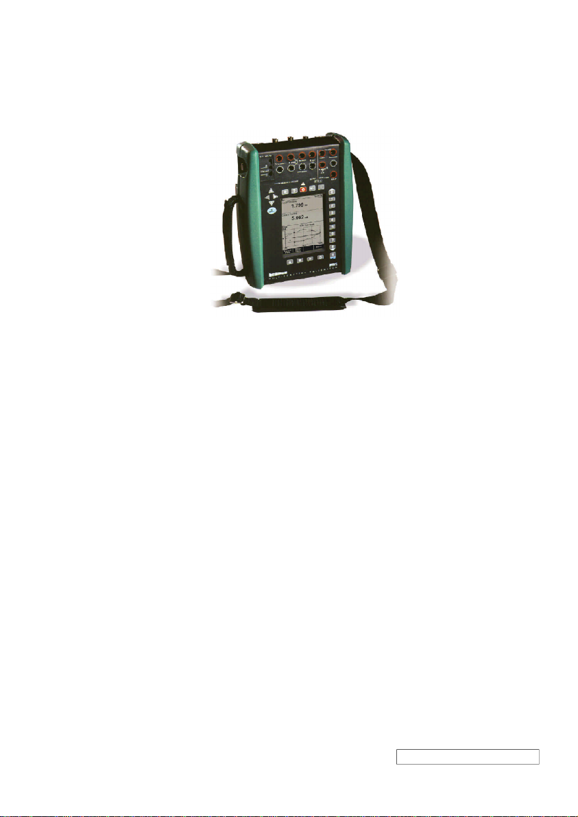
CL560
MULTIFUNCTION CALIBRATOR
User Guide
Applies for Main Firmware version 1.90
Dear user,
We have made every effort to ensure the accuracy of the contents of this manual.
Should any errors be detected, we would greatly appreciate to receive suggestions
to improve the quality of the contents of this manual.
The above not withstanding, we can assume no responsibility for any errors in this
manual or their eventual consequences.
We reserve rights to make modifications to this manual without any further notice.
(8822000) / CL560 / 012512
Page 2

Trademarks
HART® is a registered trademark of the HART Communication Foundation.
Other trademarks are property of their respective owners.
Contents
Any use of the word “HART” hereafter in
this document implies the registered trademark.
Page 3

Contents
Part A, General
Contents
Introduction 2
About This Manual .................................2
Typographical Conventions ..............3
Unpacking and Inspection......................3
CL560 Hardware 4
Operational Sections and Connections..4
The Upper Panel ..............................5
The Connectors on the
Left Side of CL560............................6
The Front Panel................................7
Memory ................................................10
Batteries ............................................... 11
About the Charger and
the Charging Procedure .................12
Removing/Replacing the
Battery Pack ...................................13
Support for Table Top Use....................14
The Wrist Strap and
the Neck Support Strap ........................14
The Optional Carrying Case.................14
CL560 Firmware 15
General Description .............................15
Startup Procedure...........................15
Basic Mode.....................................16
Maintenance ...................................16
Calibration Mode ............................16
Help Function .................................17
Printing ...........................................17
The User Interface ...............................18
The Status Bar................................18
The Function Key Bar.....................19
Menus.............................................19
The Display Area ............................20
CL560’s Modularity and Options 24
Hardware modules/options ..................24
Other Connectable devices ............25
Firmware options..................................25
Safety 26
Certifications and Compliances
(EC Declaration of Conformity) ............26
Safety Precautions and Warnings........27
General Warnings ..........................27
Warnings Concerning the use
of Electrical Modules (E and ET) ....28
General Warnings Concerning
Pressure Measurement ..................28
Warnings Concerning
High Pressure.................................29
Service 30
Firmware Update..................................30
Recalibrating CL560 ............................30
The Battery Charger.............................30
Cleaning CL560 ...................................31
Cleaning the Contacts of the
Internal Reference Junction
Module............................................31
Page 4

Contents
Part B, Startup and Basic Operation
Starting CL560 34
Startup Procedure ................................34
Basic Mode, Defined ............................35
Measuring 37
Pressure Measurement........................39
Using Internal Modules...................39
Using External Modules..................39
Zeroing a Pressure Module ............40
Current Measurement ..........................41
External supply ...............................41
Internal Supply ...............................41
Voltage Measurement ..........................42
Measuring Low Voltages ................42
Measuring Voltages up to ±50 V.....43
Resistance Measurement ....................44
Switch State Sensing ...........................45
Limit Switch Test ..................................46
Performing the Limit Switch Test ....46
Frequency Measurement .....................48
Pulse Counting.....................................49
RTD Measurement (Temperature) .......50
Thermocouple Measurement
(Temperature).......................................51
Internal Reference Junction ...........51
External Reference Junction ..........51
Special Measurements 53
Mathematical Special Measurements ..54
Minimum value ...............................54
Maximum value ..............................54
Min/Max value.................................54
Rate of Change ..............................54
Special Filtering and Resolution .....55
Deviation Measurement..................55
Special Measurements Using
Two Ports Simultaneously ....................56
Difference Measurement ................56
Redundant Measurement ...............57
Generating/Simulating 58
General ................................................58
Changing the Value of the
Generated/Simulated Signal ..........59
Current Generation ..............................60
Using the ET module’s
output terminals ..............................60
Using the E module’s
output terminals ..............................60
Voltage Generation ..............................62
Generating Voltages up to ±12 V....62
Low Voltage Generation .................62
Frequency Generation .........................64
Pulse Generation .................................65
RTD and Resistance Simulation ..........66
Thermocouple Simulation ....................67
Internal Reference Junction ...........67
External Reference Junction ..........67
Special Generations 69
Opening the Step or Ramp
Configuration Window..........................69
Stepping ...............................................70
Ramping...............................................71
Alarm Limit Settings 73
Page 5

Contents
Part C, Advanced Operation and Configurations
Configuring the Calibrator 76
Settings ................................................76
Setting Time and Date..........................78
Advanced Utilities 79
Measuring the Environment
Temperature with the ENV Sensor .......79
Display Mode Settings .........................80
Scaling............................................81
Displaying Values in Percentage ....82
Displaying Error Values ..................82
Transmitter/Switch Simulation..............83
Transmitter Simulation....................84
Switch Simulation ...........................85
Data Logging........................................86
General...........................................86
Configuring .....................................86
Starting the Data Log......................87
Viewing the Results ........................88
Transferring the Results to
a Personal Computer......................88
Generating Signals Using
External Devices ..................................89
Controlling the External Device
in Basic Mode .................................90
Pressure Controller Settings...........91
Temperature Controller Settings.....92
Printing .................................................93
Additional Information 94
Things to Consider when
Measuring Pressure .............................95
General...........................................95
Pressure Type ................................95
Pressure Modules and their
Naming Conventions ......................96
Square Rooting ..............................96
Thermocouple Measurement/Simulation,
Connections and Troubleshooting .......97
Internal Reference Junction ...........97
External Reference Junction ..........98
Error situations .............................100
Resistance and RTD Measurement,
Connections .......................................101
4-wire System...............................101
3-wire System...............................101
Using a Compensation Loop ........102
2-wire System...............................102
Current Measurement Parallel to
a Test Diode, Connections .................103
Parallel Functions in CL560 ...............104
Page 6

Part D, Calibration
Contents
General 106
Phases of Instrument Calibration .......107
As Found Calibration ....................108
Adjustment ...................................108
As Left Calibration ........................109
Required Modules for Different
Input/Output Signal Combinations .....110
Calibrating an Instrument 112
Selecting the Instrument
to Be Calibrated .................................112
The Instrument Window ..................... 113
A Calibration Procedure Using CL560 114
About Automatic Calibration .........116
About Manual Calibration .............116
Autocapture Feature..................... 117
Examples of Instrument Calibration ... 117
Pressure Transmitters
and Sensors ................................. 118
Temperature Sensors ...................120
Temperature Indicators
and Recorders ..............................122
Electrical Limit Switches ...............124
Using External Devices in
Calibration Mode ................................126
CL560’s Support for Instrument
Adjustment .........................................127
Maintaining CL560’s Instrument
Database 128
Adding New Instruments ....................128
Editing Instrument Data......................129
General Data Page.......................129
Instrument Input Page ..................130
Instrument Output Page ...............130
Calibration Settings Page .............131
Calibration Instructions Page .......132
Deleting Instruments ..........................132
Viewing Calibration Results 133
Calibration Result Windows ...............134
How to Choose Which Calibration
Run is Viewed...............................134
Deleting Calibration Results...............134
Appendix 1,
User Guide for
MC5 CL560 Option 136
Appendix 2,
Technical Data 150
Appendix 3,
Quick Guide for the
CL560 Datalog Viewer 156
Appendix 4,
Index 160
Page 7
General
Things discussed in Part A:
· An introduction to what CL560 is
and what the parts of this User
Guide concentrate on.
· A general description of CL560s
hardware.
· A general description of CL560s
firmware.
· The modularity and options of
CL560.
· Safety precautions and warnings.
· Briefly about how to service
CL560.
Page 8
General
Introduction
Congratulations for selecting the ultimate calibration tool!
CL560 is a documenting All-In-One Multifunction Calibrator with calibration capability of pressure, temperature, electrical and frequency
signals. CL560s modularity allows customized construction. If requirements increase in the future, new functionality may be added
by getting additional modules, e.g. adding temperature and/or electrical modules to an CL560 that previously only included pressure
modules.
Thanks to the logical user interface CL560 is very easy to use. The
large backlit graphical display guides the user in different languages
and it displays results both numerically and graphically.
CL560 performs automatic calibration of pressure, electrical and
temperature process instruments. It is capable of communicating
with external devices such as pressure controllers. CL560 also communicates with HART field instruments.
CL560 represents the state of the art in accuracy, adaptability and
all-round usability.
About This Manual
2
This User Guide is divided in four parts: A, B, C and D.
· Part A discusses general matters. There is also a chapter about
safety.
· Part B describes the basic use of CL560 such as measuring
and generating signals.
· Part C handles configuration level usage, some optional
software utilities and also offers some additional information
concerning pressure measurement, RTD and T/C measurement/simulation.
· Part D concentrates on calibration and matters related to
calibration like handling instrument data.
The even page header displays the title of the active part. The odd
page header displays the main subject (Heading level 1).
The header of each odd page also indicates the active part as shown
in the adjacent picture (with Part B active). Use the information provided in the headers as a quick guide when searching for a particular subject.
Page 9
Typographical Conventions
All examples of user interface texts are printed using 8 pt Arial
Black, e.g.
Selected port: ET:TCi(mea)
All front panel texts (fixed texts on MC5s cover) are printed using
8pt Eurostile, e.g.
Connectors marked T/C,LowV
Function and Menu keys are often referred to using both the key
name in 8 pt Eurostile and the corresponding text (function) displayed on the screen in 8 pt Arial Black, e.g.
Function key D/Menu
Unpacking and Inspection
At the factory each new MC5 passes a careful inspection. It should
be free of scrapes and scratches and in proper operation order
upon receipt. The receiver should, however, inspect the unit for any
damage that may have occurred during transit. If there are signs of
obvious mechanical damage, package contents are incomplete, or
the instrument does not operate according to specifications, contact the purchasing sales office as soon as possible. The standard
accessories are as follows:
· Calibration Certificate
· This User Guide
· Warranty Card
· Battery Pack, NiMH
· Charger for the Battery Pack
· Computer communication cable
· If any internal pressure modules are present:
A pressure hose set
· If the E module is present: Two test leads and clips
· If the ET module is present: Four additional test leads and
two clips
Introduction
For a description of available hardware and software options, see
CL560s Modularity and Options on page 24.
If you have to return the instrument to the factory for any reason,
use the original packing whenever possible. Include a detailed description of the reason for the return.
Warning!
The accessory polyurethane hose supplied with the calibrator
is rated to the maximum pressure of 20 bar at 21°C (290 psi at
70°F). Applying higher pressure can be hazardous.
3
Page 10

General
CL560 Hardware
General features:
· IP65 water/dust proof case (EN60529)
Battery pack IP30.
· Integrated impact protectors
· Both a wrist strap and a neck support strap
· A support for using the calibrator on the table
· Operating temperature: -10 +50 °C (14122°F).
+10 +40 °C (50104°F) when charging the batteries.
· Storage temperature: -20 +60 °C (-4140°F).
Note: The stickers and the batteries may be affected when
storing longer periods in extreme conditions.
· Humidity: 0 80 %RH
More comprehensive specifications are available in Appendix 2.
Operational Sections and Connections
E x t e r n a l
P r e s s u r e
T h e
M o d u l e s
I n t e r n a l
P r e s s u r e
M o d u l e s
E n v i r o n m e n t
T e m p e r a t u r e
S e n s o r I n t e r f a c e
C o m p u t e r /
P r i n t e r
I n t e r f a c e
A u x i l i a r y
I n s t r u m e n t
I n t e r f a c e
T h e
L e f t
S i d e
U p p e r
P a n e l
E l e c t r i c a l
M o d u l e
( E M o d u l e )
E l e c t r i c a l a n d
T e m p e r a t u r e M o d u l e
( E T M o d u l e )
R e f e r e n c e
J u n c t i o n M o d u l e
( R J M o d u l e )
T h e
F r o n t
P a n e l
All sections and connections are presented in detail on the next
pages.
Note.
Keep in mind that the previous picture (as well as all pictures of
CL560 in this manual) has an example configuration of modules.
The configuration of your CL560 may vary significantly from the
one in the picture.
4
Page 11

The Upper Panel
The upper panel has 5 places for the following modules/connectors:
External Pressure Modules
CL560 has a connector for External Pressure Modules (EXTs). The
connector is located on the right hand side of the upper panel and
is marked with PX1 in a sticker on the upper panel.
Internal Pressure Modules
Up to three Internal Pressure Modules may be installed in CL560.
One of them may be an internal barometric module. Although the
Barometric Module reserves the space allocated for an internal pressure module it does not need a connector in the upper panel, so the
space reserved for the connector may be used for, e.g. a connector
for an External Pressure Module.
The connectors for Internal Pressure modules start from the second connector on the left. The possible Barometric Module is always located as second from right and it measures the barometric
pressure through a connection in the back panel of MC5. Normally
nothing need to connected to the barometric pressure modules
connector.
Internal pressure modules are marked with P1 P3. The Barometric Module does not have an abbreviation. The whole name is
written on the module.
The recommended pressure medium for all internal pressure modules is clean air. Clean non-corrosive liquids may optionally be used
in modules with a measuring range of 20bar/300psi or more. Avoid
spilling liquid on CL560 when connecting/disconnecting pressure
hoses to/from pressure modules.
To avoid damaging the calibrator, use hand tightening only when
connecting the pressure measurement hoses (max. torque 5 Nm,
approx. 3.6 lbfft). If the use of tools is required to secure the connection (typically pressure modules with a pressure range higher
than 20 bar), apply the counterforce with a spanner on the connector bodys hexagonal part.
The overpressure protection of the internal pressure modules vents
to the back of the calibrator. Remember to be cautious when working with pressure and pressure modules. See also chapters Safety
on page 26 and Safety Precautions and Warnings on page 27.
CL560 Hardware
5
Page 12

General
The Connectors on the Left Side of CL560
The left side of CL560 (front view) has three connectors as follows:
Environment Temperature Interface
This connector is for an optional temperature measurement sensor. This sensor is only meant for environment temperature measurement. It should not be used as a reference sensor when calibrating temperature instruments.
Computer/Printer Interface
The COMP/PRT connector may be used when connecting to a serial port in a PC. The PC may have a calibration software capable of
communicating with CL560 or, e.g. a software that reads data logging results in CL560 and transfers them to a PC.
The same connector can be used when CL560 is connected to an
optional portable printer. The printer may be used for printouts of
user interface screens (e.g. calibrations results).
Warning!
Use only cables provided by Beamex when connecting CL560
to a PC or a printer.
Auxiliary Instrument Interface
The AUX connector is used when connecting pressure controllers,
temperature baths/dry blocks etc. to CL560.
Using auxiliary instruments is described in Part C of this manual.
6
Page 13
The Front Panel
The front panel has several sections. Some of them are pointed out
with a callout in the picture of Operational Sections and Connections, and some of them not (e.g. display and keyboard). The ones
with a callout are discussed first in the following paragraphs.
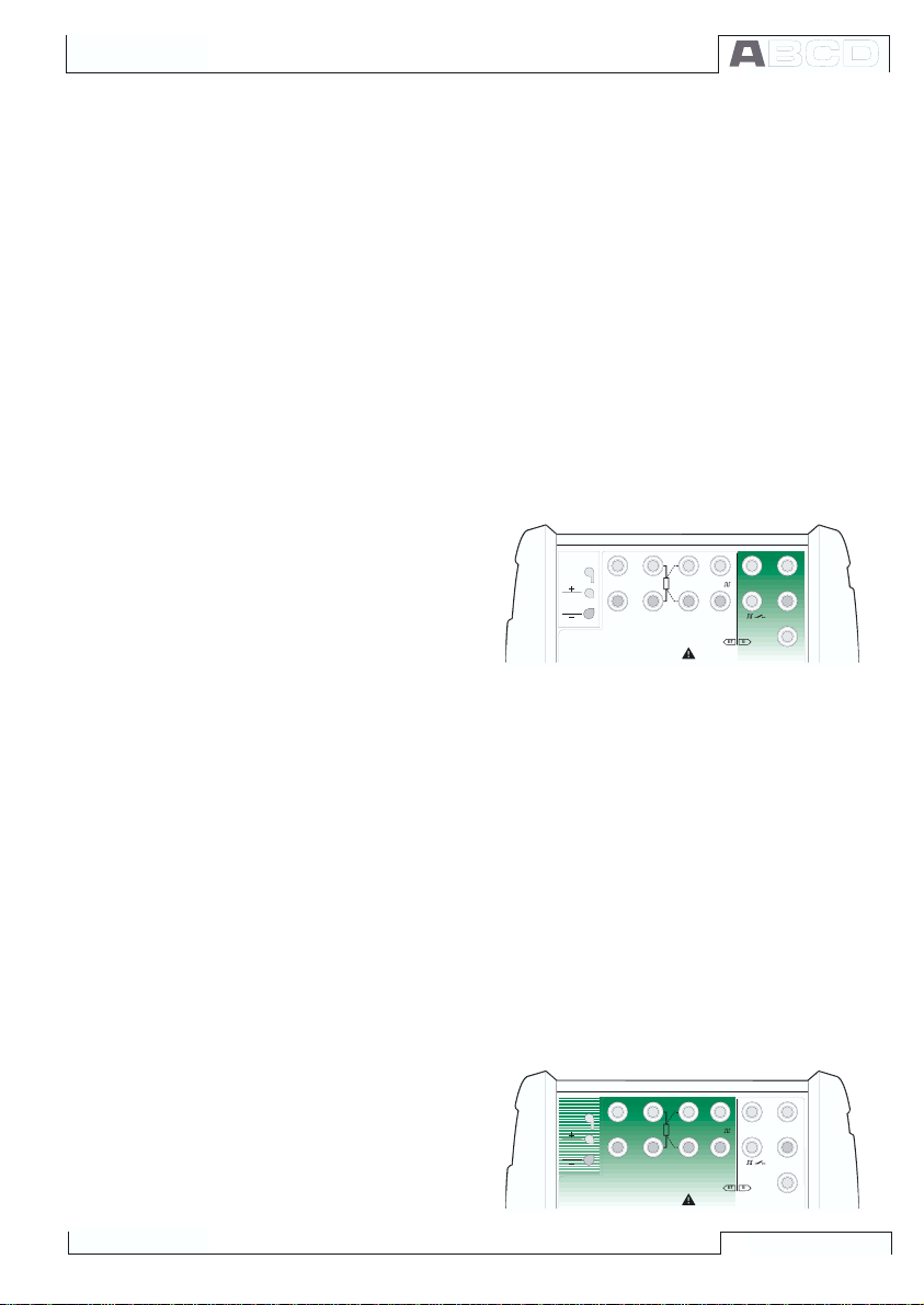
Electrical Module (E module)
The E module can measure the following quantities: voltage, current and frequency. It can also be used when counting pulses or
detecting the state of a switch. Additionally there is a possibility to
generate current and supply an instrument with a 24VDC power
supply.
The E module also includes the optional HART modem. This allows
communication with an instrument with HART capabilities. When
HART is used in conjunction with MC5s power supply, an internal
270 ohm resistor
needed for HART communication is automatically included.
Additional information
on calibrating HART instruments is in Appendix 1.
CL560 Hardware
T / C IN T . R J
T / C , L o w V
T / C O R E X T
W I R E S O N L Y
2 - w x m t r
+ 2 4 V
4 - w m e a s
R , R T D
3 & 4 - w m e a s
V , 1,
O U T P U TS E N S O R M E A S U R E & S I M U L A T E
6 0 V D C / 3 0 V A C
E T E
M a x in p u t :
V , ,
H A R T
M E A S U R E
1
m e a s / s i n k
®
L o w V
Electrical and Temperature Module (ET module)
The ET module is specially designed for temperature instrument
calibration needs. It is not however restricted to only temperature
instrument use because it can also generate voltage, current, fre-
quency and pulses.
Measuring capabilities:
· Low Voltage measurement and T/C measurement using ei-
ther the internal reference junction or the Low Voltage connectors.
· Resistance and RTD measurement.
Generation/simulation capabilities:
· T/C simulation using either the internal reference junction or
the Low Voltage
connectors.
· Resistance and
RTD simulation.
· Voltage, current,
frequency and
pulse generation
T / C IN T . R J
T / C O R E X T
W I R E S O N L Y
T / C , L o w V
2 - w x m t r
+ 2 4 V
4 - w m e a s
R , R T D
3 & 4 - w m e a s
V , 1,
O U T P U TS E N S O R M E A S U R E & S I M U L A T E
6 0 V D C / 3 0 V A C
E T E
M a x in p u t :
V , ,
H A R T
M E A S U R E
1
m e a s / s i n k
®
L o w V
7
Page 14
General
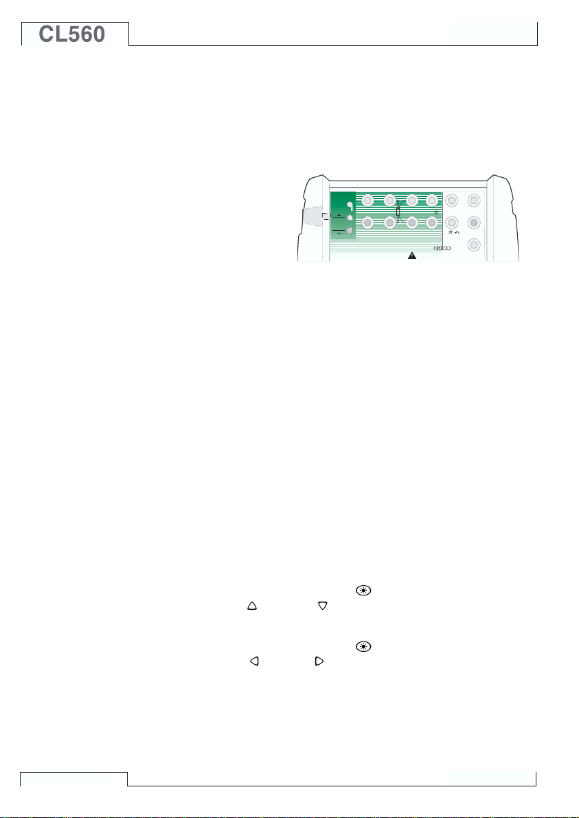
Reference Junction Module
The T/C measurement/simulation internal reference junction is an
optional addition to the ET module. It is specially designed for CL560
and therefore best suited for reference junction compensation when
calibrating thermocouples or instruments connected to a thermocouple.
The Reference Junction Module is suited for
all standard T/C plugs
and stripped wires.
Open the fixing screw
on the left side of
CL560 before connecting the wires/plug to the Reference Junction Module. Make sure to
connect the wires/plug as the polarity is indicated on the Reference
Junction Module. Remember to tighten the fastening screw when
the wires/plug are connected. Hand tightening is adequate. Do not
pull out the wires/plug without first opening the fixing screw. Otherwise you might damage the contact surface of the connectors.
T/C measurement and simulation may also be done without the
internal reference junction by using the Low Voltage terminals in
the ET module. Then the reference junction arrangements have to
be done outside CL560 and the correct reference junction settings
as well as the reference junction temperature have to be informed
to CL560.
Part B of this manual describes in detail what kind of reference
junction settings are available.
T / C IN T . R J
T / C O R E X T
W I R E S O N L Y
T / C , L o w V
2 - w x m t r
+ 2 4 V
4 - w m e a s
R , R T D
3 & 4 - w m e a s
V , 1,
O U T P U TS E N S O R M E A S U R E & S I M U L A T E
6 0 V D C / 3 0 V A C
E T E
M a x in p u t :
V , ,
H A R T
M E A S U R E
1
m e a s / s i n k
®
L o w V
Display
8
CL560 has a backlit transreflective display. The resolution of the
display is 240 x 320 pixels.
To quickly tune the contrast of the display:
· Press and hold the light button
· Use the up
and down
arrow keys to change the contrast.
down.
To quickly tune the backlight brightness:
· Press and hold the light button
· Use the left
and right
arrow keys to change the backlight
down.
brightness.
The changed settings are automatically saved as default settings.
Page 15
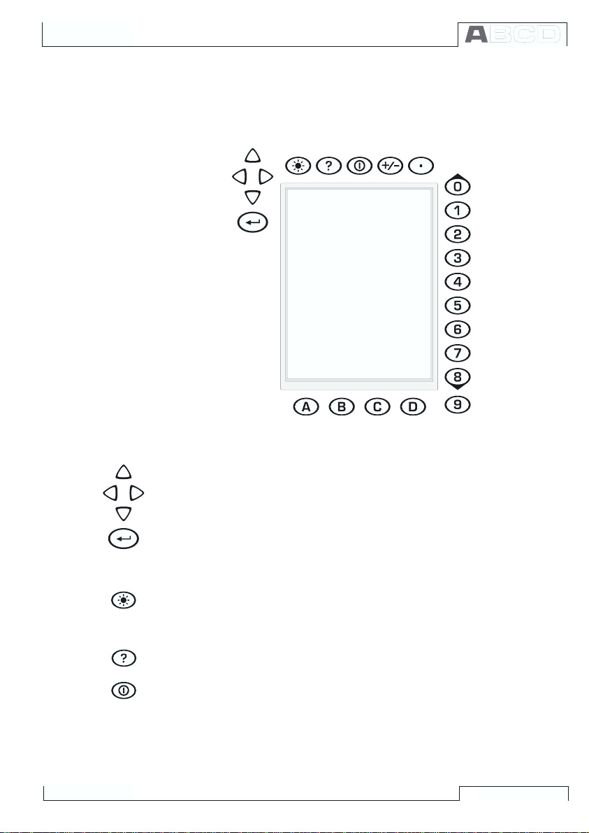
Keyboard
CL560 Hardware
The keys on the CL560s keyboard are grouped according to their
function as follows:
The Cursor Keys and the Enter Key
The Cursor keys and the Enter key are located close to the upper
left corner of the display. The Cursor keys are used when moving
the cursor on the screen. They also have several special functions
in certain situations, e.g. when tuning the contrast of the display.
The Enter key finishes the entering of values.
The Keys Above the Display
The Light key toggles the back light of the display on and off. It is
also used when setting the contrast and the brightness of the display (see chapter Display on page 8) and when printing screenshots
(see chapter Printing on page 17).
The Help key displays case sensitive help.
The On/Off key switches CL560 on and off. Press the On/Off key
for about half-a-second to switch on/off. This delayed function prevents accidental on/off switching of CL560.
9
Page 16
General
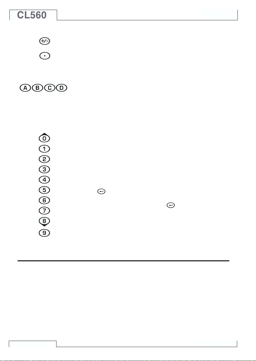
Pressing the +/- key toggles the sign of the entered numeric value.
Note. The +/- key is applicable only in numeric fields.
The Decimal key adds the decimal point to the numeric value that
is currently edited.
The Function Keys
The Function Keys are located below the display. The meaning of
each Function Key varies depending on the situation. The lower
part of the display indicates what the Function Key stands for at the
moment.
The Numeric Keys
The Numeric keys are not only used when entering numbers:
· Keys 1 to 7 are used as menu selector keys.
· Keys 0 and 8 are used to scroll through several pages of menu
options. They may also be used when browsing through options in a pop-up list.
· Key 9 can be used when accepting a selection or when finishing a data entry. The functionality of the 9 key is almost similar
to the
bers, the 9 key produces the number 9. To finish entering a
number, you will have to use the
Function Key when available.
key, except for one situation: When entering num-
key or use the D/OK
Memory
10
CL560 has a dynamic memory allocation system. This means that
there is not a specific area of memory reserved for, e.g. instrument
data. All free memory may be used for anything that requires more
memory. Thus there is no exact limit for the number of instruments
that CL560 can maintain in its memory. It all depends on how much
memory is allocated by other data.
Page 17

Batteries
Full batteries:
Empty batteries:
CL560 Hardware
CL560 supports the use of both rechargeable batteries and alkaline batteries. When using alkaline batteries, you need a Dry Battery Cartridge. CL560 automatically detects the battery type.
The alkaline batteries to be used are:
- Cell Voltage: 1.5 V
- Amount: 6
- Type: AA
The charger for rechargeable batteries operates in the following
environments:
- Voltage: 100240 VAC,
- Frequency: 50/60 Hz
The charging electronics is in the Battery Pack. Therefore the batteries may be charged although the Battery Pack is disconnected
from CL560s Base Unit. If you have two sets of rechargeable batteries you may charge the disconnected Battery Pack while at the
same time use CL560 with the connected Battery Pack.
The maximum operating time without recharging varies depending
on the usage and brightness setting of the display light. Also the
generated output current and the usage of the 24V transmitter supply affect the maximum operating time. Even with constant maximum load, the standard rechargeable batteries should last for 6
hours. A good average operating time is 10 hours.
If alkaline batteries are in use, the maximum operating time also
depends on the quality of the batteries. An average operating time
is approximately 4 hours.
The upper left corner of CL560s display shows a picture of a battery. The whiter the picture is, the more acute is the need for recharging (or changing of the alkaline batteries).
Notes.
CL560s memory and the internal clock/calendar uses a small
amount of power although the calibrator is switched off. Remember
to check the capacity of the batteries from time to time although
CL560 is not in use.
Do not leave CL560 without a Battery Pack or a Dry Battery Cartridge for a long time. CL560 may loose its settings if it is left without
a support voltage for an extended period.
11
Page 18
General
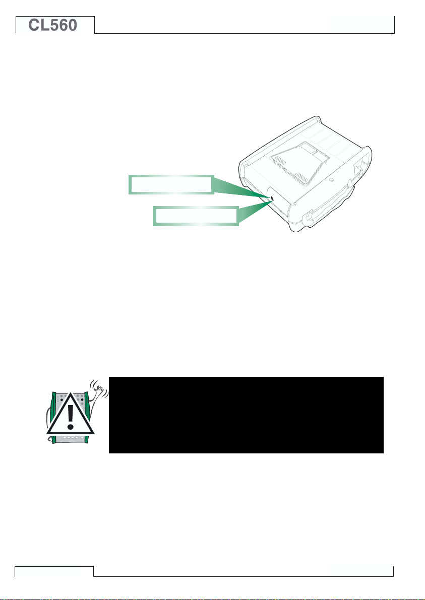
About the Charger and the Charging Procedure
The charger is connected to the charger connector at the bottom of
CL560. The charging electronics informs you of the phases of the
charging procedure with the help of the charge status light.
C h a r g e r c o n n e c t o r
C h a r g e s t a t u s l i g h t
When connecting the charger, the charging electronics first checks
the charge level of the batteries. At this stage, no light is visible in
the charge status light.
When the charge status light is red, a recharging is either starting
(blinking red light) or in progress (constant red light). CL560 may
be used during the recharging phase. Empty batteries are fully
charged in approx. 2½ hours.
When the charge status light is green, the batteries are charged. At
this stage the charging electronics provide a support voltage that
prevents the batteries from discharging
12
Warnings!
USE ONLY THE CHARGER PROVIDED WITH THE CALIBRATOR.
The charger accepts input voltages from 100 to 240VAC.
The charger should only be used indoors and the temperature
should not exceed 40 °C (104 °F).
Page 19
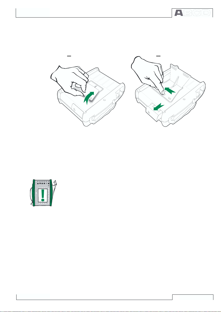
Removing/Replacing the Battery Pack
To remove or replace the Battery Pack, perform the following procedure:
1. 2.
1. Turn CL560 upside down (the display facing the table top) and
lift the support.
2. Pull the lever that is hidden under the support. The Battery
Pack pops out allowing you to pull it out.
To replace the Battery Pack, simply slide it on its place. When you
hear a click, the Battery Pack is secured in its place.
CL560 Hardware
Note.
Although the Base Unit is IP65 protected, the Battery Pack is not.
The Battery Pack has holes in order to vent generated gas and
heat. Avoid exposing the Battery Pack to liquids.
13
Page 20
General
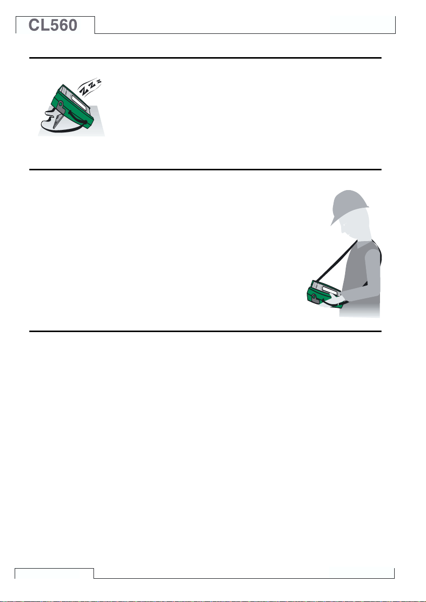
Support for Table Top Use
The support gives you a good viewing angle when CL560 is placed
on a table top. Lift the support at the back of CL560 and place
CL560 on the table top as shown in the picture.
The Wrist Strap and the Neck Support Strap
CL560 has a wrist strap to enable ease of use
when CL560 is held in one hand. The neck
support strap helps you during field calibration: Position CL560 in an angle that allows
reading the display when working. Alternatively: Hang CL560 from, e.g. a valve shaft so
that the display is on the same level as your
eyes. Then your hands are free for working
with the connections etc.
The Optional Carrying Case
CL560s soft carrying case is practical when moving from a location
to another. The carrying case can also be used for transporting
utilities, like:
· Test hoses, test leads and clips
· External pressure modules
· A pressure pump
· Temperature sensors
· Charger and its cable
· User Guide (this book)
The carrying case is suited for use in normal industrial environment.
14
Page 21
CL560 Firmware
CL560s firmware is saved in FLASH memory. Therefore it is relatively easy to update the firmware whenever a new version with
fresh capabilities is released. See Firmware Update on page 30
for more information on updating the firmware in your CL560.
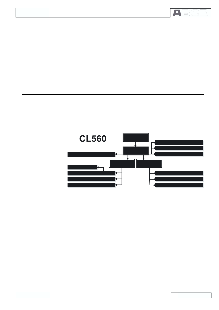
General Description
The following picture shortly describes the functions of the firmware. All main functions are marked with a black border. Each main
function has several tasks which are displayed as shaded boxes
without a black border.
M E N U S T R U C T U R E
M e a s u r e m e n t / G e n e r a t i o n / S i m u l a t i o n
I n s t r u m e n t A d j u s t m e n t
I n s t r u m e n t C a l i b r a t i o n
V i e w i n g t h e R e s u l t s
I n s t r u m e n t D a t a b a s e M a i n t e n a n c e
CL560 Firmware
S T A R T U P
S T A R T U P
P R O C E D U R E
P R O C E D U R E
B A S I C
M O D E
C A L I B R A T I O N
M O D E
M A I N T E -
M A I N T E -
N A N C E
N A N C E
T r a n s m i t t e r S i m u l a t i o n
D a t a L o g g i n g
S t e p p i n g a n d R a m p i n g
C o n f i g u r i n g t h e C a l i b r a t o r
S e t t i n g T i m e a n d D a t e
A d j u s t i n g t h e C a l i b r a t o r
Startup Procedure
The following chapters briefly describe each main function.
Every time CL560 is started the Startup Procedure checks the functionality of the device by performing a self test.
If the self-test is passed successfully, some basic calibrator data is
displayed.
After that CL560 automatically proceeds to Basic Mode. A more
comprehensive description of the Startup Procedure is in the beginning of Part B of this manual.
15
Page 22

Basic Mode
Maintenance
Calibration Mode
General
In Basic Mode you can measure and generate/simulate signals.
There are two separately configurable windows available. Basic
Mode is often used for testing connections before starting the actual calibration procedure of an instrument.
Stepping and Ramping tools enable generating/simulating signals
that vary with time.
All main functions of Basic Mode are described in part B of this
manual.
Part C concentrates on Basis States higher level functions and
additional information.
This main function handles calibrator configuration settings.
Additionally there is the possibility to recalibrate CL560 (requires a
password).
Maintenance level subjects are handled in Part C of this Manual.
CL560s main duty is calibrating instruments. Therefore very special attention was directed on this matter when creating the calibrator. CL560 may be used as a stand-alone calibrator i.e. all instrument data and calibration history data is saved in CL560s own
memory. Optionally CL560 also communicates with calibration software.
CL560 supports the use of instruction texts. They help the technician to perform the calibration as fluently as possible. You may enter three kinds of instruction texts: Starting Guide, Adjusting Guide
and Finishing Guide. Additionally, calibration notes can be entered
after the calibration procedure.
More calibration related information is available in Part D of this
manual.
Calibration Results
16
The graphical representation as well as numeric data of the calibration results may be viewed in CL560 (and printed if the optional
printer is available). Transferring the results to a calibration software makes it possible to view the results in PC environment.
More information concerning calibration results is presented in Part
D of this manual.
Page 23
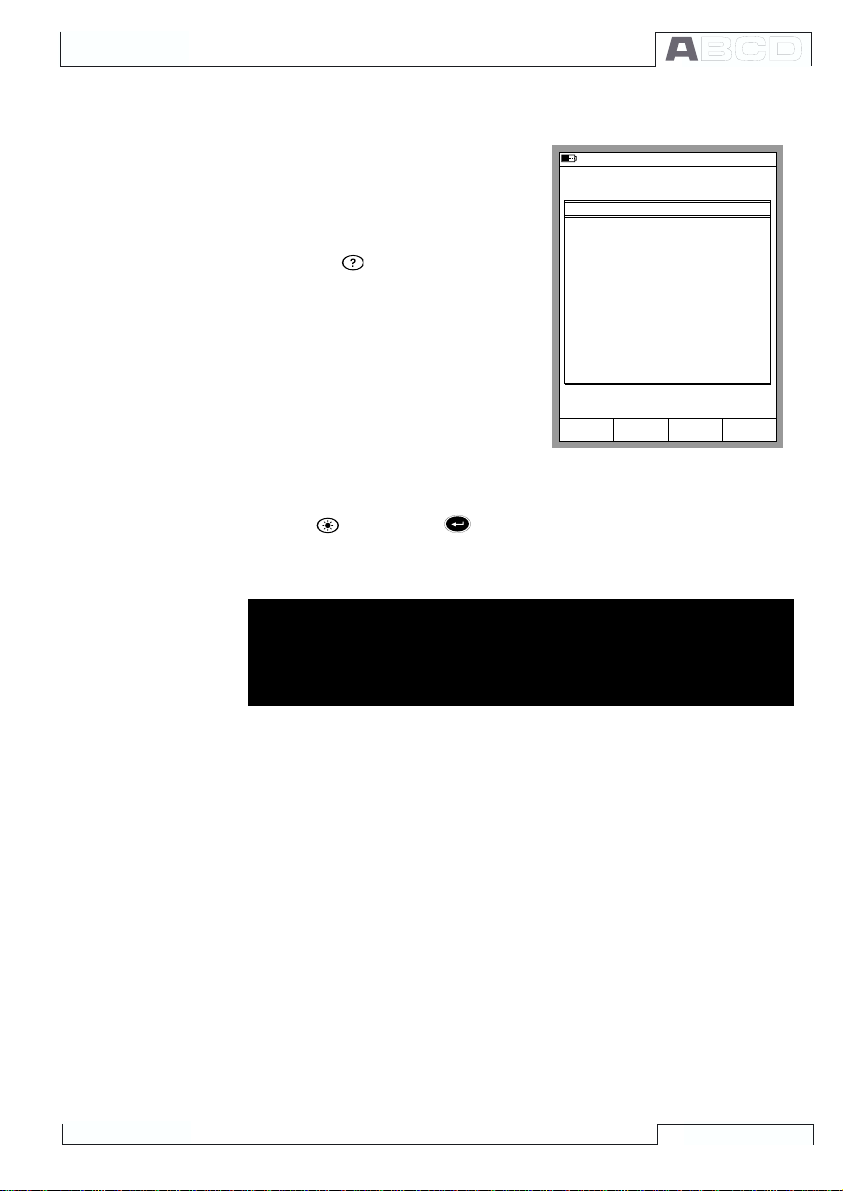
Help Function
Printing
CL560 Firmware
The Help function is not seen in the
picture of the menu structure because it is not a separate branch
but a utility available in almost any
situation. If you need help, just
press the
key. A window with
related help pops up.
2 2 . 0 9 . 2 0 0 0 1 2 : 1 5
1
V o l t a g e
E T : L o w V L o w V . S e n s o r M e a s .
B a s i c M o d e i s t h e f o c a l p o i n t o f
M C 5 ' s m e n u s t r u c t u r e .
A d v a n c e d f u n c t i o n s a r e i n D / M e n u
a n d C / O t h e r s .
T o m e a s u r e , g e n e r a t e o r s i m u l a t e ,
s e l e c t Q u a n t i t y a n d P o r t f r o m
W i n d o w 1 S e t u p o r
W i n d o w 2 S e t u p m e n u .
U s e r G u i d e :
P a r t B M e a s u r i n g
P a r t B G e n e r a t i n g / S i m u l a t i n g
C l o s e
H E L P
You can print out screenshots of any situations in CL560 by pressing the
key and the
key simultaneously.
Additional information on printing is found in part C of this manual.
Warning!
Only use the printer that is available as an option. Using any
other printers may damage the printer or CL560 or even both
of them.
17
Page 24
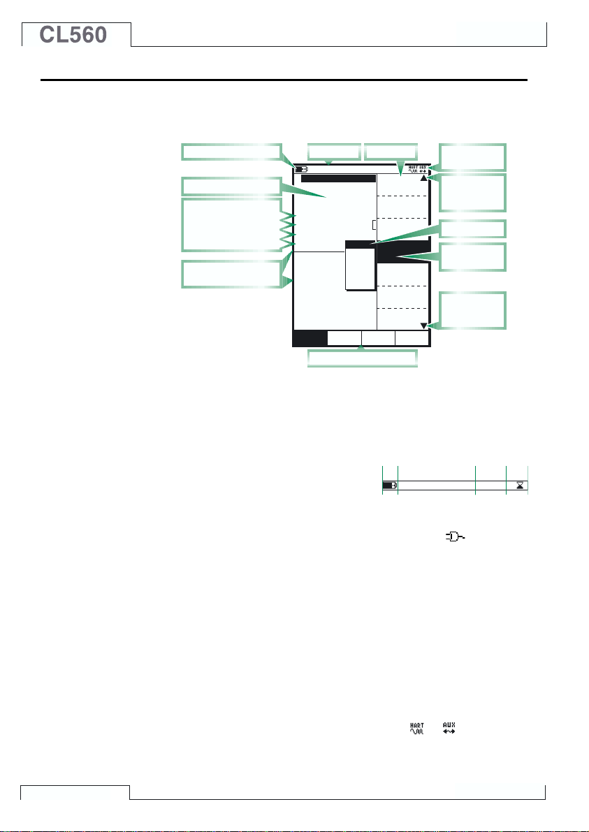
The User Interface
The main elements of the User window can be seen in the following
picture:
All possible elements are not included in the previous picture, but
the important ones are discussed in the following chapters.
The Status Bar
The Status Bar at the top
of the display is visible all
the time. It is divided into
four main sections.
The first (leftmost) section displays the charge level of the battery.
The battery symbol is replaced by a plug symbol (
using the battery charger together with the optional Dry Battery
Cartridge. In this case the battery charger acts as a battery eliminator. The second section displays the time and date. The third section displays the temperature measured with the optional environment sensor, if the sensor is connected to CL560.
The fourth section (rightmost) section displays additional information in the form of symbols, like:
Note that the fourth section is empty for most of the time. The symbols are visible only when needed.
General
B a t t e r y ' s c h a r g e l e v e l
M e a s u r e m e n t r e a d i n g
A d d i t i o n a l d a t a r o w s :
S e n s o r S u p p l y
E x t e r n a l D e v i c e
S p e c i a l M e a s u r e m e n t
E x t r a I n f o
D i s p l a y a r e a d i v i d e d
i n t o W i n d o w 1 a n d 2
S t a t u s B a r
0 6 . 0 5 . 2 0 0 2 1 3 : 5 0
P r e s s u r e
1
P 1 : I N T 2 C / - 1 . 0 0 0 0 0 0 . . . 2 b a r
0 . 4 5 2 1
E T : V o l t a g e G e n e r a t i o n
P O C 4 , b a r
M a x i m u m v a l u e : 1 . 1 2 6 2 b a r
I n t e r n a l t e m p e r a
2 C u r r e n t
E : C u r r e n t M e a s u r e m e n t
M i n i m u m v a l u e : 0 . 0 0 0 0
S e t u p S e t u p
E x a m p l e o f S t a t u s
k P a
P a
b a r
p s i
m m H
0 . 1 1 2
m m H g
F u n c t i o n k e y b a r
B a r a p p e a r a n c e
O
2
O t h e r s
M e n u
A l a r m <
Q u a n t i t y
[ P r e s s u r e ]
( g a u g e )
F u n c t / P o r t
m b a r
[ P 1 : I N T 2 C ]
0 . 5
D i s p l a y M o d e
[ E n g . U n i t ]
U n i t
[ b a r ]
H A R T
P r e s s u r e
T y p e
[ g a u g e ]
Z e r o
P r e s s u r e
M o d u l e
S e c t i o n s :
1 2 4
T i m e & D a t e
A d d i t i o n a l
i n f o r m a t i o n
I n d i c a t o r
f o r m u l t i p l e
m e n u p a g e s
b a r
P o p - u p l i s t
P r e s e n t
s e l e c t i o n
I n d i c a t o r
f o r m u l t i p l e
m e n u p a g e s
C l o s eW i n d o w 1 W i n d o w 2
M E N UM o d e
3
2 1 . 3 ° C
) if you are
· An hourglass when CL560 is working on something that takes
time.
· A question mark when an error occurred.
· A symbol indicating communication with an external device,
e.g. a HART instrument or a controller (
or
).
18
Page 25
The Function Key Bar
The Function Key Bar at the bottom of the display is visible all the
time. The meaning of the Function Keys varies depending on the
situation. A grayed Function key text means that the function is disabled at the moment.
CL560 Firmware
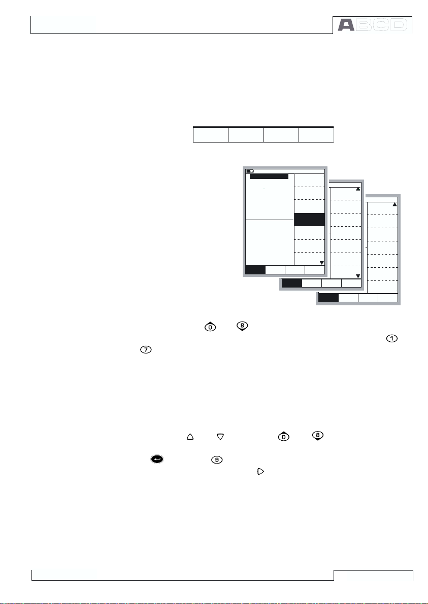
Menus
C a l i b r a t i o n
The Function Key for
opening the menu is always D/Menu. The same
key is used when closing
the menu. If a menu is not
needed for the current
subject, the fourth Function Key is used for other
needs.
If the opened menu has
several pages, the
menus uppermost and/or
lowermost item includes
F i e l d M E N U
S t o p
M o d eM o d e
R a m p i n g
0 6 . 0 5 . 2 0 0 2 1 3 : 5 7
P r e s s u r e
1
P 1 : I N T 2 C / - 1 . 0 0 0 0 0 0 . . . 2 b a r
0 . 7 0 8 3 4
2 C u r r e n t
E : C u r r e n t M e a s u r e m e n t
0 . 4 3 7 4
W i n d o w 1 W i n d o w 2
S e t u p S e t u p
C l o s e
A l a r m <
Q u a n t i t y
[ P r e s s u r e ]
( g a u g e )
F u n c t / P o r t
m b a r
[ P 1 : I N T 2 C ]
0 . 5
b a r
D i s p l a y M o d e
[ E n g . U n i t s ]
U n i t
[ b a r ]
H A R T
P r e s s u r e
T y p e
[ g a u g e ]
Z e r o
P r e s s u r e
M o d u l e
C l o s e
O t h e r s
M E N UM o d e
W i n d o w 1 W i n d o w 2
S e t u p S e t u p
S p e c i a l
A l a r m <
M e a s u r e m e n t
[ N o n e ]
( g a u g e )
A l a r m
m b a r
[ - - ( - - ) ]
S e c o n d p o r t
0 . 5
b a r
[ P 2 : E X T 1 0 0 ]
F u n c t i o n a n d
P o r t I n f o
S e c o n d
P o r t I n f o
E x t r a I n f o
C l o s e
O t h e r s
M E N UM o d e
W i n d o w 1 W i n d o w 2
S e t u p S e t u p
A l a r m <
C o n t r o l l e r
S e t t i n g s
( g a u g e )
S e n s o r S u p p l y
m b a r
[ N o n e ]
O t h e r s
b a r
0 . 5
C l o s e
M E N UM o d e
an up/down triangle. In
and
keys to browse through the available
that case, use the
menu pages. A menu option is selected with the numeric keys
to . Selecting a menu option results in one of the following events:
1. An immediate action follows and the menu closes automati-
cally, e.g. when selecting the Zero Pressure Module option
in the picture above.
2. A pop-up list opens for selecting one of the available options.
The current selection is displayed inside brackets in the menu.
Use the
and
keys or the
and
keys to scroll the
pop-up list. To select an option in the pop-up list, use either the
key or the
lecting anything, press the
key. To close the pop-up menu without se-
key or the
D/Close Function Key.
3. Another menu with new options replaces the previous menu.
Sometimes the Function Keys can also open another menu.
In the previous picture, the Window 1 setup menu is opened.
In this case Function Key B/Window2Setup and Function
Key C/Others can be used for opening other menus.
4. A new window opens for, e.g. viewing additional information or
for configuring the selected task.
19
Page 26
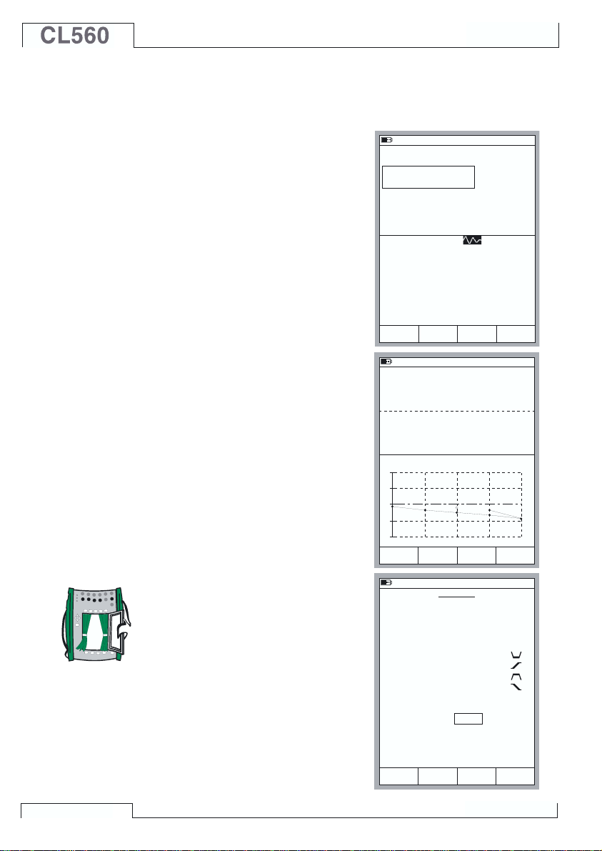
The Display Area
General
The layout of the display area varies according to the needs of the
active tasks/settings. The following
pictures give an overview of typical
elements seen in different display
area layouts.
Basic Measurement/Generation:
2 2 . 0 9 . 2 0 0 0 8 : 0 6
1
F r e q u e n c y
E T : F r e q u e n c y G e n .
1 . 0 0 0 0 0
A m p l i t u d e [ V p p ]
p o s . s q u a r e
k H z
5 . 0 0
The display area is divided into two
windows with informative texts and
numeric measurement/generation
values.
2
C u r r e n t
E : C u r r e n t M e a s u r e m e n t
1 1 . 9 8 3 7
m A
A border surrounding a numeric
value indicates that the field is
editable. It is, e.g. a generation field
for entering generation values.
If several editable fields are visible,
choose the active field with the cursor keys or the
B/Field Function
Key.
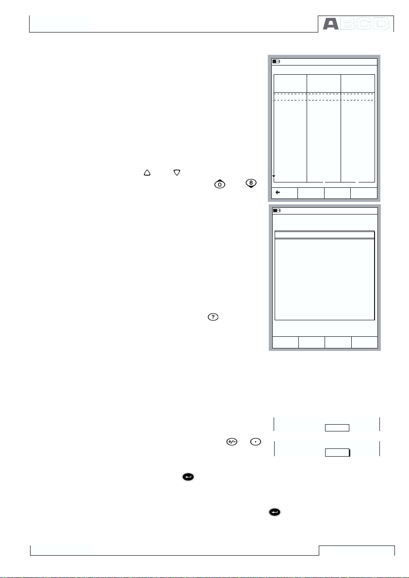
Calibration:
The display area is divided into
three windows during a calibration.
The first window displays data related to the instruments input signal. The second corresponding
data related to the output signal.
The third window displays the error graph. The error graph is also
seen among calibration result data.
Configuration Window:
There are plenty of configuration
windows in CL560. The picture beside is the configuration window for
Ramping settings.
The common thing for all configuration windows is that they reserve
the whole display area for the con-
C a l i b r a t i o n
I n p u t
O u t p u t
E r r o r
0 . 4 0
+
0
-
Q u a n t i t y
P o r t
W a i t i n 0 %
R i s e T i m e
W a i t i n 1 0 0 %
F a l l T i m e
R e p e a t s
0 = c o n t i n u o u s
F i e l d
M o d e
2 2 . 0 9 . 2 0 0 0 8 : 1 4
R T D T e m p e r a t u r e [ E T : S i m u l . ]
5 0 . 0 0
C u r r e n t [ E : M e a s . ]
1 1 . 9 9 2 5
0 % 5 0 % 1 0 0 %
F o r c e
P a u s e
A c c e p t
2 2 . 0 9 . 2 0 0 0 8 : 3 7
R A M P I N G
C u r r e n t
E : I ( g e n )
2
1
2
2
1
P t 1 0 0 =3 8 5
° C ( I T S 9 0 )
m A
- 0 . 0 5 % o f s p a n
s
s
s
s
M E N U
figuration fields.
Use the cursor keys to move between fields.
R a n g e 0 %
C a n c e l S t a r t
1 0 0 %
8 . 0 0 0 0
1 6 . 0 0 0 0
m A
20
Page 27
CL560 Firmware
Tables:
Tables are used, e.g. when viewing calibration results in numeric
format. Tables reserve the whole
display area. The tables are often
larger than the display. In that case
there are small arrows added to the
table borders. They indicate that
more information may be seen by
using the arrow keys.
and
keys scroll the list
and
The
one line at a time. The
keys scroll the list one page at a
time (if applicable).
Hint.
If the table has more columns than
can be seen, use the numeric keys
to quickly jump to corresponding
column.
Help window:
The help window is a special window. It displays help text that the
user called using the
key.
Display Area Elements that are Used for Editing Data
There are four different fields/elements that are used for editing data in the display area. Use the
B/Field Function Key to move between editable fields in Basic Mode.
In configuration windows, use the cursor keys.
Numeric Fields
There are two ways to start editing a
numeric field:
1. Press a numeric key,
or
key. Then the entered value replaces the old value.
2. Press the key or the C/Edit Function Key available in some
configuration windows. Then you can edit the old value. New
digits appear at the end of the old value.
Accept the new value by pressing the
value, use the
A/Cancel Function Key. See also Part B for special
features concerning numeric fields when generating a signal.
2 2 . 0 9 . 2 0 0 0 8 : 4 7
1 2 . 0 2 . 2 0 0 0 1 0 : 2 9 - A s F o u n d - P a s s e d
I n p u t
- 0 . 0 0 0 0 2
0 . 9 9 9 9 6
1 . 9 9 9 9 8
3 . 0 0 0 0
4 . 0 0 0 0
5 . 0 0 0 0
6 . 0 0 0 0
7 . 0 0 0 0
8 . 0 0 0 0
9 . 0 0 0 0
9 . 9 9 9 9
9 . 0 0 0 0
8 . 0 0 0 0
B a c k
2 2 . 0 9 . 2 0 0 0 1 2 : 1 5
1
V o l t a g e
E T : L o w V L o w V . S e n s o r M e a s .
B a s i c M o d e i s t h e f o c a l p o i n t o f
M C 5 ' s m e n u s t r u c t u r e .
A d v a n c e d f u n c t i o n s a r e i n D / M e n u
a n d C / O t h e r s .
T o m e a s u r e , g e n e r a t e o r s i m u l a t e ,
s e l e c t Q u a n t i t y a n d P o r t f r o m
W i n d o w 1 S e t u p o r
W i n d o w 2 S e t u p m e n u .
U s e r G u i d e :
P a r t B M e a s u r i n g
P a r t B G e n e r a t i n g / S i m u l a t i n g
C l o s e
R a n g e 0 %
R a n g e 0 %
O u t p u t
P a g e
1 0 0 %
1 0 0 %
N e x t
[ V ]
- 0 . 0 0 0 0 5
0 . 9 9 9 9 6
2 . 0 0 0 0
3 . 0 0 0 1
4 . 0 0 0 1
5 . 0 0 0 2
6 . 0 0 0 1
7 . 0 0 0 1
8 . 0 0 0 1
9 . 0 0 0 2
1 0 . 0 0 0 1
9 . 0 0 0 2
8 . 0 0 0 2
H E L P
[ V ]
1 2
4 . 0 0 0 0
1 6 . 0 0 0 0
4 . 0 0 0 0
2 0 _
E r r o r
0 . 0 0 3
0 . 0 0 0
0 . 0 0 2
0 . 0 0 1
0 . 0 0 1
0 . 0 0 2
0 . 0 0 1
0 . 0 0 1
0 . 0 0 1
0 . 0 0 2
0 . 0 0 2
0 . 0 0 2
0 . 0 0 2
[ % ]
key. To discard the edited
M E N U
m A
m A
21
Page 28
General
Notes.
You cannot add more digits if the length of the number is at its
maximum limit. Use the C/çDelete Function Key to remove unwanted digits first and then enter the new digits.
The dual function of the keys: ,
and
is not available in a
numeric field. The keys only represent numbers.
Text fields
P o s i t i o n I D
P T 1 0 6 . 1
Press any of the numeric keys or
C/Edit Function Key available
the
in some configuration windows to
start editing a text field. Then the
menu with the available characters
opens for selecting. Use the numeric keys (1 to 7) to select the
character. Use the cursor keys to
move the cursor in the text field.
Select the character with the
the
key. Use the C/çDelete
or
Function Key to remove unwanted
characters. If the character you
want to use is not seen in the list of
available characters, try the
the
key to see more alternatives.
or
1 6 . 1 0 . 2 0 0 0 1 5 : 2 1
P T 1 0 6 . 1
D e v i c e I D
D e v i c e N a m e
E r r o r C a l c . M e t h o d
R e j e c t i f
A d j u s t i f
D o n o t A d j u s t i f
A d j u s t t o
C a n c e l D e l e t e A c c e p t
% o f s p a n
>
0 . 5 0
>
0 . 3 0
<
0 . 1 0
<
0 . 1 0
A B C
D E F
G H I
J K L
M N O
P Q R
S T U
V W X
Y Z Å
Ä Ö O
Æ Ë Ï
Ü Â Ê
Î Ô
Û Ç ß
Accept the new text with the D/Accept Function Key. To discard
(cancel) the edited text, use the A/Cancel Function Key.
22
Page 29
CL560 Firmware
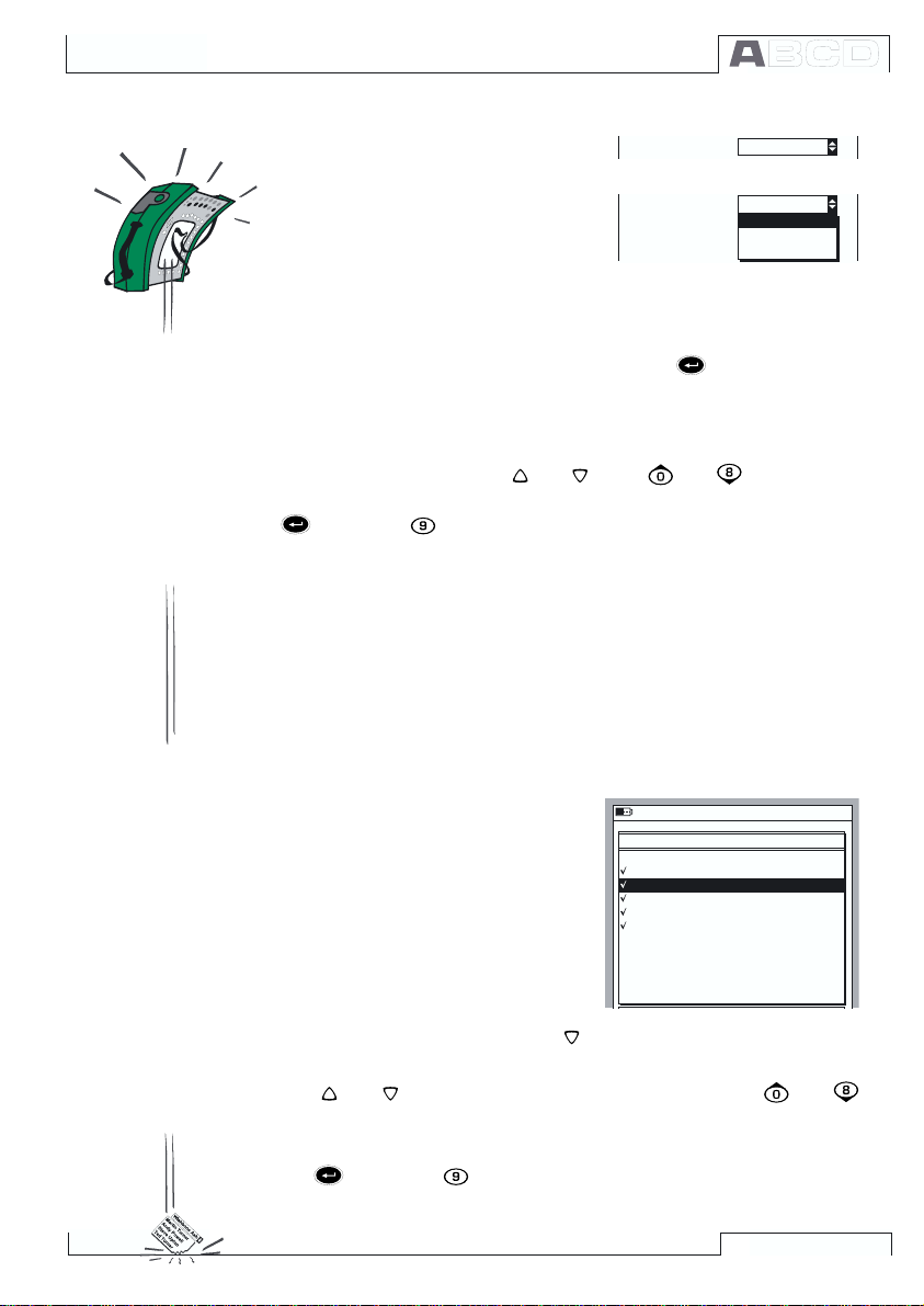
Drop Down Lists
I n p u t M e t h o d
M e a s u r e d
Drop Down Lists are used when
there is a limited amount of preset
values. You have to select one of the
available options. The list of available options is displayed either be-
I n p u t M e t h o d
M e a s u r e d
M e a s u r e d
K e y e d
C o n t r o l l e d
low or above the Drop Down List
field.
A Drop Down List opens when you press the
key or any of the
numeric keys or the C/Edit Function Key available in some configuration windows. Small arrows in the upper right and/or lower right
corner indicates that the list is longer than the visible part.
Use either the cursor keys
and
or the
and
keys to scroll
through the available options. Select one of the options with the
key or the
key.
Pop-up Lists
Pop-up Lists are similar to Drop Down Lists except that Pop-up
Lists appear in conjunction with menus. Theres a picture of a Popup List in chapter The User Interface on page 18.
Scrolling a Pop-up List can be done with an additional way (compared Drop Down Lists): Each time you push the numeric menu
key that opened the Pop-up List, the cursor advances one step.
Selection Lists
Selection lists are used when you
have to choose one of several options. Selection lists are often large,
thus almost reserving the whole
window.
Selection lists can be longer than
the visible part. When the cursor
(the row with the inverted text) is
1 6 . 1 0 . 2 0 0 0 1 5 : 2 1
P O S I T I O N / D E V I C E I D
1 0 1 - X L - 0 0 1 . 1
1 1 2 - T T - 0 0 3 . 1
1 1 2 - T T - 0 0 7 . 1
E S w
P T 1 0 6 . 1
P T 1 1 2 . 1 2
P T 1 1 2 . 1 5 - 1
P T 1 1 2 . 1 5 - 2
P T 1 1 2 . 1 6
T I
V V
on the bottom and you press the
key, the list scrolls and displays more options.
The
and
keys scroll the list one line at a time. The
and
keys to scroll the list one page at a time (if applicable).
Select one of the options with the C/Select Function Key or either
the
key or the
key.
23
Page 30
General
CL560s Modularity and Options
CL560 includes several optional modules both in hardware and firmware. This makes it possible to buy a calibrator with capabilities
according to current requirements. If additional needs arise later
on, add more modules to your CL560 and you will have a tool that
suits all demands.
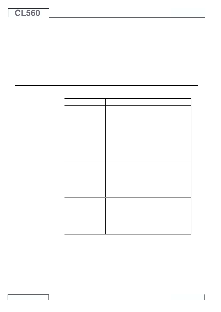
Hardware modules/options
MODULE DESCRIPTION
Base Unit (BU)
Internal Pressure
Modules
(P1, P2 and P3)
External Pressure
Module connector
(PX1)
Electrical Module
(E)
Electrical and
Temperature
Module (ET)
Internal Reference
Junction Module
(RJ)
(1
Required module. Includes the case,
display, keyboard, battery pack, common
electronics and the ENV, AUX and
COMP/PRT connectors as well as a
connector for an external pressure module
(PX1).
Modules with positive and compound
gauge pressure measurement capability
and a barometric module enabling also
absolute pressure measurement together
with other modules.
Connection for external modules capable
(1
of measuring high pressures up to 1000
bar (approx. 14500 psi).
Voltage, low voltage, current and frequency
measurement. Also pulse counting, switch
testing, HART communication
generation, and 24 V loop supply.
Resistance, RTD and thermocouple
measurement/simulation. Low voltage
measurement/generation. Voltage, current,
frequency and pulse generation.
Internal reference junction compensation
for thermocouple measurement/simulation.
Cannot be used without the ET Module.
(2
, current
24
All CL560s are built around the Base Unit (BU). All other modules
are optional, but at least one of the optional hardware modules has
to be available in order to measure/generate/simulate a signal.
1)
There are some limits on the total amount of certain modules/
connectors. See chapter The Upper Panel on page 5 for additional information concerning this matter.
2)
E modules HART communication requires that the respective
firmware option is installed.
Page 31

Other Connectable devices
There is an increasing number of devices that can be connected to
CL560. The following list includes connectable devices that are either already connectable or will be in soon to come firmware updates (valid when this manual was printed):
· External Pressure Modules (EXT)
· Environment temperature sensor (ENV)
· Battery operated portable printer (COMP/PRT)
· Pressure Controllers: POC4,
Druck DPI510 and Druck DPI 515 (AUX)
· Temperature Baths/Dry Blocks: Isotech,
TekKnow, Ametek/Jofra and HART Scientific (AUX).
Additional information on the battery operated portable printer, pressure controllers and temperature baths/dry blocks is available in
partC of this manual.
Firmware options
The standard firmware shipped with CL560 is capable of performing all normal measurement, generation/simulation and calibration
tasks. The optional tools give you additional features that enhance
CL560s functionality.
The following firmware options are either already available or will
be in soon to come firmware updates (valid when this manual was
printed):
· Special temperature sensors
· Drivers for External Devices that are connected to the AUX
interface.
· HART communication (Requires the E module)
· Multichannel datalogging
CL560s Modularity and Options
25
Page 32

General
Safety
CL560s case is water/dust proof (IP65). The battery pack does
however have holes to enable proper ventilation and heat transfer.
So be careful when working in wet conditions.
The materials of CL560s case withstand normal industrial conditions. CL560 endures shocks with the help of the built in impact
protectors
Internal pressure modules with a measuring range of 6 bar (90 psi)
or less are overpressure protected. If the measurement pressure of
a pressure module exceeds the modules maximum pressure value,
the overpressure protector vents excess pressure through a hole in
the rear of the case.
Certifications and Compliances (EC Declaration of Conformity)
CL560 conforms to the EMC directive 89/336/EEC as attested by
conformity with the following harmonized standards:
EN 50081-1 Emission,
EN 50081-1 Immunity,
EN 61000-3-2 Harmonic currents,
EN 61000-3-3 Voltage fluctuations,
and the low voltage directive 73/23/EEC as attested by conformity
with the following harmonized standard:
EN 60950 Low Voltage.
26
Page 33

Safety Precautions and Warnings
CL560 calibrator is a precision calibration tool that should be used
by skilled people. Working with CL560 involves the usage of pressure, temperature and/or electrical instruments. Be sure to know
how to work with these instruments and how to safely connect/disconnect pressure hoses as well as electrical test leads clips, etc.
Use CL560 only if you are certain of that it can be used safely. Safe
use of CL560 is no longer possible if one or more of the following
cases are true:
· When the case of CL560 is evidently damaged
· When CL560 is not functioning as expected
· After prolonged storage in unfavorable conditions
· After serious damage during transport
Sometimes it is necessary to use a portable radio transceiver while
working with the calibrator. To prevent calibration errors caused by
the radio frequency interference, keep the radio far (at least 1 meter)
from the calibrator and the circuit under calibration while sending.
General Warnings
Use only cables provided by Beamex when connecting MC5 to
a PC or a printer.
Use the CL560 battery charger in a non-hazardous indoor location only and only with this calibrator.
Only use the printer that is available as an option. Using any
other printers may damage the printer or CL560 or even both
of them.
CL560 uses alkaline batteries or a rechargeable Battery Pack.
All of these battery types are considered as hazardous waste.
Dispose used batteries properly according to local regulations.
Avoid short circuiting the batteries. The short circuit current
may cause burns to you, damage to the device or even fire.
Notice, that also new replacement batteries are shipped in
charged state.
Rechargeable batteries may vent small amounts of gas during
recharge. The vented gas mixture may be highly explosive, but
normally it diffuses rapidly into the atmosphere. To avoid danger, use only the original charger and never recharge in a gastight container.
The charger should only be used indoors and the temperature
should not exceed 40 °C (104 °F).
Safety
27
Page 34

General
Warnings Concerning the use of Electrical Modules (E and ET)
The measurement and generation terminals of CL560 are protected against over voltage and over current as far as it has
been possible without affecting the accuracy. The circuits are
designed so, that you can connect a voltage source 50VDC/2A
between any terminals without damaging the device. However,
long exposure to this kind of stress may affect the accuracy.
Although there is a galvanic isolation between CL560s ET and
E modules, it is for functional purposes only. The max. 50 V
restriction applies between these modules too.
Maximum output voltage from CL560s terminals is below 30V.
If you, however, connect together voltages from the ET and E
sections or if you connect external voltages to MC5, the resulting voltage may be high enough to be hazardous.
General Warnings Concerning Pressure Measurement
The accessory polyurethane hose supplied with an CL560 with
pressure modules is rated to the maximum pressure of 20bar
at 21°C (290psi at 70°F). Applying higher pressure can be hazardous.
To avoid damaging the calibrator, use hand tightening only
when connecting the pressure measurement hoses (max.
torque 5 Nm). If the use of tools is required to secure the connection (typically pressure modules with a pressure range of
20 bar or more), apply the counterforce with a spanner on the
connector bodys hexagonal part.
Always depressurize the system before opening or connecting
any pressure fittings or connectors. Use proper valves for venting the system. Ensure that all connections are made correctly
and that the hose and the connectors are intact.
Always use the pressure media stated in the modules sticker.
Using unsuitable pressure media may destroy the pressure
module. The internal modules sticker is located at the rear of
CL560. External modules have the sticker on the module itself.
Never exceed the maximum pressure of a pressure module, be
it internal or external. The pressure modules maximum pressure is stated on the modules sticker. The maximum pressure
of external modules is also mentioned in the Instruction Leaflet that is provided with the external module.
Never plug a hose with your hands or put the hands in front of
a gas spray coming from a leakage. A gas bubble in the blood
circulation can cause death.
28
Page 35

Warnings Concerning High Pressure
High pressure is always dangerous. Only personnel with good
experience and knowledge of high pressure liquid, air and nitrogen operations are allowed to work with the module. Read
carefully all these instructions and local safety instructions for
high pressure operations before starting the use.
When using gas, the system must not contain any liquid, especially if you do not know how they may react under pressure.
Use of clean air or nitrogen is recommended as gaseous pressure media. Liquid pressure media should be preferred when
using modules with a pressure range of 60 bar (30000 psi) or
more.
If you use nitrogen, minimize the leak to the atmosphere and
take care of sufficient ventilation. Close the valve of the nitrogen cylinder, when the system is not in use. Increase in the
percentage of nitrogen in the ambient air may cause unconsciousness and death without warning. Read carefully the
safety instructions for nitrogen and make sure that the other
people in the same space are aware of the danger.
Use of liquid pressure medium is recommended with pressure
measurement modules at higher pressure range. Use water or
suitable hydraulic oil. Check that the used liquid is not aggressive against the materials used in the transducer or tubing.
When using liquid, minimize the amount of air in the system.
So you can minimize the amount of spilled liquid in case of
leakage.
Do not use the same tubing with different liquids or gases.
Check what the local regulations say about construction and
use of pressurized vessels. The regulations normally control
construction and use of systems where the product of the pressure and volume exceeds a certain limit. The volume of this
system depends on the instrument connected to it.
High pressure gas is dangerous because it can break the container and the flying splinters may cause injury. Also small leaks
of gas may be dangerous because the high velocity of the leaking gas jet enables penetration through skin. If a gas bubble
gets into the blood circulation, it can cause death. The leak jet
is particularly penetrative, if some liquid is coming with the
gas.
Safety
29
Page 36

Service
Firmware Update
General
Only qualified service personnel may perform higher level maintenance for CL560. Never open the case unless have explicit in-
structions from Omega or a local representative.
There are, however a few things that anyone using CL560 may do.
The quickest way to see if a new firmware version is available is
checking out Omegas web site. Go to the Downloads page and
see what it says about CL560 firmware versions and downloads.
All you need is a Personal Computer and the Computer communication cable that connects MC5 to one of the serial ports in your
PC.
Remember to backup all the instrument data in CL560, using e.g. a
calibration management software. Also check for possible release
notes accompanying the updated file.
Recalibrating MC5
The Battery Charger
30
Contact Omega or your local representative for information concerning the recalibration of CL560.
The charger is not intended to be serviced. When unusable it can
be thrown away according to local waste disposal regulations.
Page 37

Service
Cleaning MC5
If CL560 needs cleaning, use cloth soaked with a mild solution of
tall oil soap (pine soap). Wait a a few minutes and then rinse using
a cloth moistened with pure water. Never use any strong detergents.
Cleaning the Contacts of the Internal Reference Junction Module
The contacts of the Internal Reference Junction Block may need
cleaning from time to time. The time period varies depending on
the environment CL560 is used in.
Carefully open the cover of the Internal Reference Junction Block
by using a screwdriver as a wrench. Now you can see the contacts.
Remove all impurities and press back the cover. The cover is secured when you hear a click.
31
Page 38

General
(Empty)
32
Page 39

Startup and Basic
Operation
Things discussed in Part B:
• What happens during the
• Measuring signals and doing
• Generating/simulating signals.
• Step and Ramp functions.
• Alarm limits.
startup procedure.
some special measurements.
Page 40

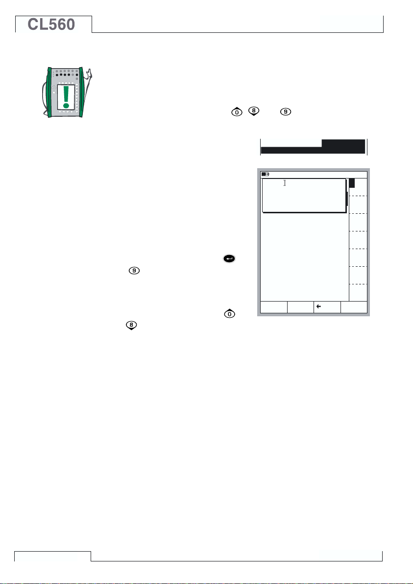
Startup and Basic Operation
Starting CL560
Startup Procedure
When CL560 is started, a startup picture appears. After a self test,
some basic information of the calibrator at hand appears in the lower
part of the screen. If you want to view the calibrator information for
a longer period, press the D/Wait function key. Then the calibrator
information is visible until you press the D/Continue function key.
25.11.2002 13:52
www.beamex.com
Serial number
Main version
E module version
ET module version
Calibration due date
23512365
1.90
1.50
1.70
20.03.2003
Wait
If a module’s version number cannot be seen, the module is not
included in the CL560 at hand.
The calibration due date that is listed in the startup window is the
earliest calibration due date for all connected modules. If the calibrator requires recalibration, CL560 stops at the calibrator information window and the text “Calibrate Soon” appears below the calibration due date row.
Page 41

35
Basic Mode, Defined
Every time CL560 is switched on, the startup procedure ends in
Basic Mode.
All non-calibration related measurements and generations are performed in the Basic Mode. Briefly: in Basic Mode CL560 works like
a high quality multimeter. When returning from CL560’s higher level
operations (calibration, viewing of calibration results, calibrator and
user configurations), you always return to the Basic Mode.
Starting CL560
Basic Mode:
Measurement
Generation...
Where
should I go
today...
In Basic Mode, the two available measurement/ generation/
simulation windows have default settings based either on factory
settings or settings defined when CL560 was previously used.
The first time the D/Menu key is pressed, the Window 1 Setup
menu is available. Other possible menus can be selected from the
function keys: B/Window 2 Setup and C/Others. The latter function
key opens a menu with some special functions and also includes
the possibility to go to higher level operations.
Page 42

Startup and Basic Operation
Example of a Basic Mode screen
with pressure measurement configured in Window 1 and current measurement configured in Window 2:
What can be done in Basic Mode
• Measure signals (*
• Generate signals (*
• Simulate signals (*
• Start special measurement (min/max value etc.)
• Perform a Limit Switch Test
• Set alarm limits
• Use the ramping function
• Use the stepping function
*) Available options depend on the installed modules.
22.05.2000 8:33
1
Pressure
P2:INT20C/-1.0000...20.6840 bar g
2.6475
2
Current
E: Current Measurement
12.4731
Calibration
Mode
gauge
bar
mA
MENU
Next…
Measuring on page 37
Generating/Simulating on page 58
Special Measurements on page 53
Alarm Limit Settings on page 73
Special Generations on page 69.
Page 43

37
Measuring
Measuring
All measurements in Basic Mode require that you first select the
Window to be used (Commands: Start with D/Menu and continue
either with A/Window 1 Setup or B/Window 2 Setup). Each measurement has its own unique 1/Quantity and 2/Function/Port set-
tings in their window’s menu. The other window menu settings, e.g.
measuring unit, refine the measurement characteristics.
When presenting measurements in this manual, the first paragraph
tells the module (or modules) that is/are required for the measurement. Because of CL560’s modularity you may or may not have the
required module. If the module is not included in your CL560, the
1/Quantity and 2/Function/Port settings needed for the measure-
ment are not available as choices in the pop-up lists.
Each measurement also has at least one picture with a circle around
some of CL560’s terminals, like the one below.
V, I,
OUTPUTSENSOR MEASURE & SIMULATE
Max input:
60 VDC/30 VAC
2-w xmtr
+24V
I
meas/sink
V, ,
®
HART
MEASURE
ET E
Low V
T/C INT. RJ
T/C OR EXT
WIRES ONLY
T/C, Low V
T/C, Low V
R, RTD
4-w meas
3 & 4-w meas
The circle indicates active terminals for each 1/Quantity and
2/Function/Port setting in the window menu.
If the picture has more than two terminals circled, then the lighter
part is somehow optional. In the following picture, the HART terminal is optional during current measurement.
2-w xmtr
V, I,
ET E
Max input:
60 VDC/30 VAC
2-w xmtr
+24V
+24V
I
I
meas/sink
V, ,
®
HART
MEASUREOUTPUTSENSOR MEASURE & SIMULATE
Low V
T/C INT. RJ
T/C OR EXT
WIRES ONLY
T/C, Low V
R, RTD
4-w meas
3 & 4-w meas
Page 44

Startup and Basic Operation
Warning!
Do not apply voltage higher than 50 V (max 2 A) between any
terminals.
Page 45

39
Measuring
Pressure Measurement
See chapter Things to Consider when Measuring Pressure on page 95 for more information on pressure measurement and internal/external pressure modules.
Required settings Options/description
Quantity Pressure
Pressure Type g gauge pressure or
abs absolute pressure.
The available pressure types may be restricted because of the selected pressure port /
pressure module. For more information concerning pressure types, see chapter Pres-
sure Type on page 95 .
Using Internal Modules
Select an internal pressure module port
with a suitable measuring range and with
an ability to measure the required pressure
type:
Port P1: INTxxxx,
P2: INTyyyy or
Using External Modules
Select an external pressure module port
with a connected pressure module and a
suitable measuring range and with an ability to measure the required pressure type,
e.g.:
Port PX1: EXTxxxx
P3: INTzzzz.
T/C INT. RJ
T/C OR EXT
WIRES ONLY
T/C, Low V
R, RTD
SENSOR MEASURE & SIMULATE
4-w meas
3 & 4-w meas
V, I,
+24V I MEAS/SINK
V, HART
MEAS & IOUTPUT
ET E
2-w xmtr
®
GEN
T/C INT. RJ
T/C OR EXT
WIRES ONLY
Low V
Connecting and Removing External Pressure Modules
An external pressure module may be connected and removed at
any time. If a removed module was part of an active measurement,
CL560 automatically changes the measurement to a suitable internal pressure module. CL560 also emits a “beep” to inform you of
the fact that the external pressure module used for pressure measurement was disconnected.
T/C, Low V
R, RTD
SENSOR MEASURE & SIMULATE
4-w meas
3 & 4-w meas
2-w xmtr
MEAS/SINK
+24V I
V, I,
®
V, HART
MEAS & IOUTPUT
GEN
ET E
Low V
Page 46

Startup and Basic Operation
Configuring a Supply Voltage or Current to the Pressure Sensor
To configure the pressure
sensor supply setting, Open
the appropriate window
setup menu (select D/Menu,
A/Window 1 Setup or
B/Window 2 Setup). Con-
tinue to the third submenu
by pressing the numerical
key
twice. The adjacent
picture displays all the
submenus available when
06.05.2002 15:32
Pressure
1
P1: INT2C / -1.000000...2 bar
0.70834
2 Current
E: Current Measurement
0.4374
Window 1 Window 2
Setup Setup
Others
Window 1 Window 2
Setup Setup
Alarm <
Quantity
[Pressure]
(gauge)
Funct/Port
mbar
[P1: INT2C]
0.5
Display Mode
[Eng. Unit]
Unit
[bar]
HART
Pressure
Type
[gauge]
Zero
Pressure
Module
the selected Quantity is
Pressure.
Select 2/Sensor Supply and choose either Current or Voltage supply. A field for entering the supply Voltage/Current value appears in
the pressure measurement window.
Zeroing a Pressure Module
If the selected pressure module does not display zero gauge pressure when the applied pressure is zero, the module has to be zeroed.
Open the appropriate window setup menu (D/Menu, A/Window 1
Setup or B/Window 2 Setup) and select menu option
7/Zero Pressure Module. If a secondary pressure module is ac-
tive in the selected window, a pop-up menu will appear for choosing
either to zero the primary or the secondary pressure module.
Special
Alarm <
Measurement
[None]
(gauge)
bar
Alarm
[--(--)]
Second port
[P2: EXT100]
Function and
Port Info
Second
Port Info
Extra Info
Close
MENUMode
Others
Window 1 Window 2
Setup Setup
mbar
0.5 bar
MENUMode
Close
Alarm <
Controller
Settings
(gauge)
Sensor Supply
mbar
[None]
Others
0.5 bar
Close
MENUMode
Next…
NOTE!
Zeroing a pressure module is especially important when the
operating position of CL560 is changed or the location of CL560
is changed in the vertical direction. Both of the above mentioned factors affect notably on the pressure measurement modules. Measuring pressure below 100 mbar (approx. 40 iwc)
should be done with a firmly mounted CL560 (e.g. placed on a
table top).
Special Measurements on page 53
Alarm Limit Settings on page 73
Special Generations on page 69
Calibration, see Part D.
Page 47

41
Measuring
Current Measurement
The current measurement terminals are located in the E module.
Required settings Options/description
Quantity Current
Funct/Port E: I(meas)
External supply
When the measuring circuit includes an
external power supply, use the terminals
shown in the picture below.
2-w xmtr
V, I,
Max input:
60 VDC/30 VAC
2-w xmtr
+24V
I
I
meas/sink
meas/sink
V, ,
®
HART
MEASUREOUTPUTSENSOR MEASURE & SIMULATE
ET E
Low V
T/C INT. RJ
T/C OR EXT
WIRES ONLY
T/C, Low V
4-w meas
R, RTD
3 & 4-w meas
Based on the terminals in use, CL560 automatically acts as either a
pure current measuring unit or as a current measuring unit while at
the same time supplying the measuring circuit.
Notes.
Check the polarity of your connections. The arrows in the previous
pictures describe the correct flow of current.
If you are using a transmitter with HART capability, make also a
connection to CL560’s HART terminal. For more information concerning HART connections, see Appendix 1, chapter Connecting
CL560 and a HART Instrument on page 138. Information concerning current measurement parallel to a test diode can be found
in part C, chapter Current Measurement Parallel to a Test Diode,
Connections on page 103.
Internal Supply
When you want to use CL560’s 24 V terminal to supply the measuring circuit, use the
terminals shown in the picture below.
2-w xmtr
V, I,
OUTPUTSENSOR MEASURE & SIMULATE
60 VDC/30 VAC
ET E
Max input:
+24V
+24V
V, ,
HART
MEASURE
®
2-w xmtr
I
I
meas/sink
Low V
T/C INT. RJ
T/C OR EXT
WIRES ONLY
T/C, Low V
R, RTD
4-w meas
3 & 4-w meas
Next…
Current Generation on page 60
Special Measurements on page 53.
Alarm Limit Settings on page 73.
Calibration, see Part D.
Page 48

Startup and Basic Operation
Voltage Measurement
The E module has terminals for low voltage measurement within the range ±1 V and
terminals for voltage measurement within ±50 V range. The ET module also has low voltage measurement terminals with a range of ±500 mV. The ET module terminals are also
used when measuring/simulating thermocouples using an external Reference Junction.
Required settings Options/description
Quantity Voltage
Funct/Port ET: LowV(mea), E: LowV(mea) or E: V(meas)
Measuring Low Voltages
Select either Function/port ET: LowV(mea)
or E: LowV(mea) and choose a suitable
unit. The following pictures display the active terminals for both available ports.
CL560 displays the measured low voltage in the selected window.
Hint!
Low voltage measurement can be used for non-standard thermo-
couple measurement. You will see the measured temperature in
millivolts and need a table to convert the measured millivolt value to
corresponding temperature values. In this case, use copper extension cords to connect the non-standard thermocouple to CL560’s
terminals.
ET: LowV(mea), ±500 mV:
T/C INT. RJ
T/C OR EXT
WIRES ONLY
T/C, Low V
T/C, Low V
R, RTD
4-w meas
3 & 4-w meas
V, I,
OUTPUTSENSOR MEASURE & SIMULATE
60 VDC/30 VAC
ET E
Max input:
E: LowV(mea), ±1 V:
T/C INT. RJ
T/C OR EXT
WIRES ONLY
T/C, Low V
R, RTD
4-w meas
3 & 4-w meas
V, I,
60 VDC/30 VAC
ET E
Max input:
+24V
V, ,
HART
MEASURE
V, ,
MEASUREOUTPUTSENSOR MEASURE & SIMULATE
2-w xmtr
I
meas/sink
®
Low V
2-w xmtr
+24V
I
meas/sink
®
HART
Low V
Page 49

43
Measuring Voltages up to ±50 V
Select Function/port E: V(meas) and choose a suitable unit.
Measuring
Next…
V, I,
OUTPUTSENSOR MEASURE & SIMULATE
Max input:
60 VDC/30 VAC
2-w xmtr
+24V
I
meas/sink
V, ,
®
HART
MEASURE
ET E
Low V
T/C INT. RJ
T/C OR EXT
WIRES ONLY
T/C, Low V
R, RTD
4-w meas
3 & 4-w meas
CL560 displays the measured voltage in the selected window.
Warning!
Do not apply voltages higher than 50 V between any of CL560’s
terminals.
Voltage Generation on page 62
Thermocouple Measurement (Temperature) on page 51
Special Measurements on page 53.
Alarm Limit Settings on page 73.
Calibration, see Part D.
Page 50

Startup and Basic Operation
Resistance Measurement
Resistance measurement terminals are located in the ET module.
Required settings Options/description
Quantity Resistance
Funct/Port ET: R(meas)
The following picture displays the active
terminals:
V, I,
Max input:
60 VDC/30 VAC
2-w xmtr
+24V
I
meas/sink
V, ,
®
HART
MEASUREOUTPUTSENSOR MEASURE & SIMULATE
ET E
Low V
T/C INT. RJ
T/C OR EXT
WIRES ONLY
T/C, Low V
R, RTD
R, RTD
4-w meas
4-w meas
3 & 4-w meas
Note.
If the measured resistance value is infinite or very high (> 4000 ohm),
the text “+OVER” is displayed in the measuring window. This means
that the circuit is broken or the connection is wrong. Wrong connection may also cause erroneous reading, typically too low. If necessary, use the 2-wire ohm measurement to check the wiring before
final connection.
Next…
RTD and Resistance Simulation on page 66
RTD Measurement (Temperature) on page 50
Special Measurements on page 53.
Alarm Limit Settings on page 73.
Calibration, see Part D.
The two leftmost terminals are used in 2wire systems. CL560 automatically checks
the connection and displays the found wiring system (2-wire, 3-wire or 4-wire) in the
measuring window. For more information
concerning wiring options, see Resistance
and RTD Measurement, Connections on
page 101.
Page 51

45
Measuring
Switch State Sensing
The switch state detection terminals are located in the E module.
Required settings Options/description
Quantity Switch
Funct/Port E: Switch (selected automatically when the
corresponding Quantity setting is activated )
Also check the Sound setting. The option
Change means that CL560 beeps every
time the switch changes its state. When
using options Open or Closed the sound
is continuously on when the switch is
open respectively closed.
The contact should be free of external potential. If this is not possible, use DC voltage within the range -10 V to +30 V. CL560
Hint!
Switch state detection may also be used for binary signal detection.
Next…
Limit Switch Test on page 46
Calibration, see Part D.
shows voltages above approx. +1.5 V as
open contact and voltages below approx.
+1.5 V as closed contact.
V, I,
ET E
Max input:
60 VDC/30 VAC
2-w xmtr
+24V
I
meas/sink
V, ,
®
HART
MEASUREOUTPUTSENSOR MEASURE & SIMULATE
Low V
T/C INT. RJ
T/C OR EXT
WIRES ONLY
T/C, Low V
R, RTD
4-w meas
3 & 4-w meas
Page 52

Startup and Basic Operation
Limit Switch Test
A limit switch test displays the opening and closing point of a limit
switch. CL560 supports limit switch testing of any type of limit
switches as long as CL560 is able to either measure or generate/
simulate the switch’s input signal and is also capable of detecting
the switch state.
Notes.
Basic Mode’s limit switch test is a restricted version compared to
the limit switch test available in Calibration Mode. This test gives
you the approximates of the latest opening and closing points and
also the current switch status. The limit switch test in Calibration
Mode offers more accurate results and additionally, statistical data
of repeated switch tests. More of the limit switch test in Calibration
Mode in Part D of this manual.
In Basic Mode CL560 does not support limit switch testing when
simulating resistance or an RTD sensor. The limit switch test in
Calibration Mode also supports resistance and RTD sensor input.
Performing the Limit Switch Test
Configure, e.g. Window 1 to either measure or generate/simulate the switch’s input signal (Function keys D/Menu and
A/Window 1 Setup in Basic Mode) and
Window 2 for switch state detection (Function keys D/Menu and B/Window 2 Setup
in Basic Mode). It doesn’t matter which window is assigned for which function as long
as both the switch’s input signal and the
switch state are available for CL560.
Slowly change the switch’s input signal and
watch how the “Opened @” and “Closed
@” data is updated as the switch changes
its state.
07.01.2002 15:15
1
Voltage
ET: Voltage Generation
1.87000
Measurement V
2
Switch
E: Switch Sense
Closed
Opened @ V
Closed @ V
Calibration
Mode
Field
V
Stop
Ramping
1.86712
0.98549
1.29990
MENU
Page 53

47
Measuring
Note.
The accuracy of the “Opened @” and “Closed @” values depend
greatly on the change rate of the switch’s input signal.
Hint.
If you use CL560 to generate/simulate the switch’s input signal,
you can use ramping to create changing input signals for the switch
under test.
Where to find more information when measuring a switch’s input signal…
Pressure Measurement on page 39
Using External Modules on page 39
Voltage Measurement on page 42
Current Measurement on page 41
Thermocouple Measurement (Temperature) on page 51
RTD Measurement (Temperature) on page 50
Where to find more information when generating a switch’s input signal…
Voltage Generation on page 62
Current Generation on page 60
Thermocouple Simulation on page 67
Ramping on page 71
Page 54

Startup and Basic Operation
Frequency Measurement
The frequency measurement terminals are located in the E module.
Required settings Options/description
Quantity Freq.
Funct/Port E: f(meas)
Also check the Unit setting.
CL560 compares the external potential
against an adjustable reference voltage
(Trigger Level, range: -1 … +15 V) when
measuring the frequency.
Next…
Switch State Sensing on page 45
Pulse Counting on page 49
Frequency Generation on page 64
Calibration, see Part D.
T/C INT. RJ
T/C OR EXT
WIRES ONLY
T/C, Low V
R, RTD
4-w meas
3 & 4-w meas
V, I,
Max input:
60 VDC/30 VAC
2-w xmtr
+24V
I
meas/sink
V, ,
®
HART
MEASUREOUTPUTSENSOR MEASURE & SIMULATE
ET E
Low V
Page 55

49
Measuring
Pulse Counting
The pulse counter terminals are located in the E module.
Required settings Options/description
Quantity Pulses
Funct/Port E: Pls(count)
Also check the Trigg.Edge setting.
CL560 compares the external potential
against an adjustable reference voltage
(Trigger Level, range: -1 … +15 V) when
counting pulses.
The counter may be cleared (zeroed) by selecting D/Menu, 6/Clear
counter.
Next…
Frequency Measurement on page 48
Switch State Sensing on page 45
Pulse Generation on page 65
Calibration, see Part D.
T/C INT. RJ
T/C OR EXT
WIRES ONLY
T/C, Low V
R, RTD
4-w meas
3 & 4-w meas
V, I,
ET E
Max input:
60 VDC/30 VAC
2-w xmtr
+24V
I
meas/sink
V, ,
®
HART
MEASUREOUTPUTSENSOR MEASURE & SIMULATE
Low V
Page 56

Startup and Basic Operation
RTD Measurement (Temperature)
RTD-measurement terminals are located in the ET module.
Required settings Options/description
Quantity RTD-Temp.
Funct/Port ET: RTD(mea)
Sensor Type Available RTD sensors
The following picture displays the active
terminals:
V, I,
ET E
Max input:
60 VDC/30 VAC
2-w xmtr
+24V
I
meas/sink
V, ,
®
HART
MEASUREOUTPUTSENSOR MEASURE & SIMULATE
Low V
T/C INT. RJ
T/C OR EXT
WIRES ONLY
T/C, Low V
R, RTD
R, RTD
4-w meas
4-w meas
3 & 4-w meas
Note.
If the measured resistance value is infinite or very high (> 4000
ohm), the text “+OVER” is displayed in the measuring window. This
means that the circuit is broken or the connection is wrong. Wrong
connection may also cause erroneous reading, typically too low. If
necessary, use the 2-wire ohm measurement to check the wiring
before final connection.
Next…
RTD and Resistance Simulation on page 66
Thermocouple Measurement (Temperature) on page 51
Resistance Measurement on page 44
Special Measurements on page 53.
Alarm Limit Settings on page 73.
Calibration, see Part D.
The two leftmost terminals are used in 2wire systems. CL560 automatically checks
the connection and displays the found wiring system (2-wire, 3-wire or 4-wire) in the
measuring window. For more information
concerning wiring options, see Resistance
and RTD Measurement, Connections on
page 101.
Page 57

51
Measuring
Thermocouple Measurement (Temperature)
Thermocouple measurement terminals are located in the ET module.
Required settings Options/description
Quantity T/C-Temp
Funct/Port ET: TCi(mea) (for the internal Reference Junction), or
ET: TCx(mea) (for other RJ compensation methods)
Sensor Type Available thermocouples
Reference Junction Depends on the Function/Port setting.
See subsequent chapters.
Second port Available only if RTD sensor is not used as the Reference
Junction compensation method.
Internal Reference Junction
CL560’s Internal Reference Junction Module is an optional module. To use the Internal Reference Junction, select Function/
Port ET: TCi(mea). The Reference Junction compensation method Internal is automatically selected.
V, I,
ET E
Max input:
60 VDC/30 VAC
2-w xmtr
+24V
I
meas/sink
V, ,
®
HART
MEASUREOUTPUTSENSOR MEASURE & SIMULATE
Low V
T/C INT. RJ
T/C OR EXT
T/C OR EXT
WIRES ONLY
WIRES ONLY
T/C, Low V
R, RTD
4-w meas
3 & 4-w meas
Additional information is found in chapter
Internal Reference Junction on page 97.
External Reference Junction
To use an External Reference Junction,
select Function/Port ET: TCx(mea) and
choose one of the available Reference
Junction compensation methods: Entered,
0°C or available RTD sensors.
V, I,
ET E
Max input:
60 VDC/30 VAC
2-w xmtr
+24V
I
meas/sink
V, ,
®
HART
MEASUREOUTPUTSENSOR MEASURE & SIMULATE
Low V
T/C INT. RJ
T/C OR EXT
WIRES ONLY
T/C, Low V
T/C, Low V
R, RTD
4-w meas
3 & 4-w meas
Additional information is found in chapter
External Reference Junction on page 98.
Page 58

Next…
Startup and Basic Operation
Note.
CL560 has a comprehensive set of predefined sensor types. Addi-
tional sensor types are available as options.
Warning!
If you connect an RTD sensor to the ET module’s R, RTD con-
nectors, there is no galvanic isolation between the thermocouple and the RTD sensor.
Thermocouple Simulation on page 67
RTD Measurement (Temperature) on page 50
Voltage Measurement on page 42
Special Measurements on page 53.
Alarm Limit Settings on page 73.
Calibration, see Part D.
Problems with thermovoltage measurement? See Error situations
on page 100.
Page 59

53
Special Measurements
Special Measurements
Special measurements are extra utilities that can be activated to
perform a special function alongside the normal measurement.
Only one of the special measurements may be activated at a given
time for each window/quantity. Activating another special measurement deactivates the earlier special measurement in the same window (or the earlier special measurement using the same quantity).
All special measurements are started similarly:
• Select D/Menu followed by B/Window 2 Setup if needed.
• As the special measurement setting command is located in
the window setup’s submenu, select either the numerical key
or the cursor key
• Then select 1/Special Measurements and the type of spe-
cial measurement from the provided pop-up list (or deactivate
a special measurement by selecting the option “None”).
Some of the special measurements do not require any additional
information. They start immediately after they are activated. Rate
of Change Measurement, Special Filtering and Resolution,
Redundant Measurement and Deviation Measurement do how-
ever need some additional information. Therefore when you activate them you will have to enter the required additional information
before the special measurement is started.
to open the submenu.
Notes.
Special measurements are only available in Basic Mode.
If you change any of the main settings of the measurement (Quan-
tity, Funct/Port), the defined special measurement is deactivated.
To zero/restart a special measurement without altering any main
measurement settings, do the same menu commands you used for
starting the special measurement.
Page 60

Startup and Basic Operation
Mathematical Special Measurements
Mathematical special measurements may be assigned to all measurements.
Minimum value
Start the minimum value measurement by selecting:
D/Menu and B/Window 2 Setup, if needed,
or
,
1/Special Measurements,
Minimum Reading.
Maximum value
Start the maximum value measurement by selecting:
D/Menu and B/Window 2 Setup, if needed,
or
,
1/Special Measurements,
Maximum Reading.
Min/Max value
Start the minimum/maximum value measurement by selecting:
D/Menu and B/Window 2 Setup, if needed,
or
,
1/Special Measurements,
Min/Max Readings.
Rate of Change
Start the rate of change measurement by selecting:
D/Menu
and B/Window 2 Setup, if
needed,
or
,
1/Special Measurements,
Rate of Change….
Before the special measurement
is started CL560 prompts for the
rate of change unit which can be
selected from the following options: 1/s, 1/min and 1/h.
22.09.2000 13:22
RATE OF CHANGE MEASUREMENT
Quantity
Port
Unit
Rate of Change Unit
T/C-temperature
ET: TCi(meas)
°C
1/s
StartCancel Edit
Page 61

55
Special Filtering and Resolution
Start using special filtering and
resolution by selecting:
D/Menu
and B/Window 2 Setup, if
needed,
or
,
1/Special Measurements,
Filter and Resolution….
Select the Time Constant setting
and how many decimals should be
cut off from the actual resolution of
the current measurement. The filter is a 1st order digital filter.
None means “No additional filter-
ing” and “Use the modules own resolution” respectively.
Note.
You cannot “worsen” the resolution to less than one significant digit.
Deviation Measurement
In deviation measurement the reading of the main port is compared to
a reference value. The reference
value is subtracted from the reading of the main port.
Start the deviation measurement by
selecting:
D/Menu
and B/Window 2 Setup, if
needed,
or
,
1/Special Measurements,
Deviation Meas….
You can enter the reference value
when you start the special measurement mode.
Note.
Keep in mind that when the displayed deviation reading is small
compared to the actual reading, a significant part of the deviation
value may be measurement error. See the specifications for measurement errors at the actual measurement level.
Special Measurements
SPECIAL FILTERING AND RESOLUTION
Quantity
Port
Unit
Time Constant
Decimals
The setting -1, for instance, means one
less decimals.
Quantity
Port
Measure deviation from the value
19.05.2000 13:55
T/C-temperature
ET: TCi(meas)
°C
5
-2
22.09.2000 13:32
DEVIATION MEASUREMENT
T/C-temperature
ET: TCi(mea)
22.0000
°C
s
StartCancel Edit
StartCancel Edit
Page 62

Startup and Basic Operation
Special Measurements Using Two Ports Simultaneously
The following special measurements only apply when two ports are
simultaneously used in the same window. The Second Port setting in the window’s setup menu allows you to select another port
for the same window. The Second Port setting is enabled depend-
ing on selected quantity and available modules.
Difference Measurement
In difference measurement the difference between the reading of
the main port and the second port is calculated. The reading of the
second port is subtracted from the reading of the main port.
Start the difference measurement by selecting:
D/Menu and B/Window 2 Setup, if needed,
or
,
1/Special Measurement,
Difference Meas….
Notes.
Difference measurement is not available as an option in the list of
special measurements, unless two measurement ports are activated
in the same window.
No setting window appears, but the calculated difference is displayed in the special measurement row.
The measurement value of the second port may be assigned to the
Extra Info row at the bottom of the window.
Keep in mind that when the displayed difference reading is small
compared to the actual reading, a significant part of the difference value may be measurement error. See the specifications
for measurement errors at the actual measurement level.
If the measuring spans of the selected ports are different, make
sure you do not exceed the measurement range of either port.
Page 63

57
Redundant Measurement
In redundant measurement the
measurements of the main port and
the second port are compared with
each other. If the readings differ
more than the entered limit value,
CL560 gives an audible alarm.
Start the redundant measurement by
selecting:
D/Menu
and B/Window 2 Setup, if
needed,
or
1/Special Measurement,
Redundant Meas….
You can enter the allowed deviation between the two measurements
when you start the special measurement mode.
Notes.
Redundant measurement is not available as an option in the list of
special measurements, unless two measurement ports are selected
for use in the same window.
The measurement value of the second port is displayed on the special measurement row. You may assign the allowed deviation value
to be displayed on the Extra info row at the bottom of the window.
When setting the allowed difference, take the accuracies of the
measurements into account.
If the measuring spans of the selected ports are different, make
sure you do not exceed the measurement range of either port.
Special Measurements
22.09.2000 13:41
REDUNDANT MEASUREMENT
Main Measurement
Quantity
Port
Second Measurement
Quantity
Port
While displaying the main measurement,
compares it to the second and alarms if
readings differ more than
,
0.00100
Pressure
P1
Pressure
P2
bar
StartCancel Edit
Page 64

Startup and Basic Operation
Generating/Simulating
General
This chapter and the subchapters describe only how to generate/
simulate signals using CL560’s own modules. Part C discusses the
use of external devices connected to the auxiliary interface.
CL560 is capable to perform the following generation/simulation
functions:
• Voltage generation
• Current generation
• Frequency and pulse generation
• Thermocouple simulation
• RTD and resistance simulation
Generation/simulation in Basic Mode require that you first select
the Window to be used (Commands: Start with D/Menu and continue either with A/Window 1 Setup or B/Window 2 Setup). Each
generation/simulation has its own unique 1/Quantity and 2/Func-
tion/Port settings in their window’s menu. The other window menu
settings (generation/simulation unit etc.) refine the generation/simulation characteristics.
The presentation of each generation/simulation begins with a paragraph defining the modules that include terminals required for the
generation/simulation (Most generated/simulated signals are done
with the ET module but current generation may also be done with
the E module). Because of CL560’s modularity you may or may not
have the required module. If the module is not included in your
CL560, the 1/Quantity and 2/Function/Port settings needed for
the generation/simulation are not available as choices in the popup lists.
Each generation/simulation also has at least one picture with a circle
around some of CL560’s terminals, like the one below.
V, I,V, I,
ET E
Max input:
60 VDC/30 VAC
2-w xmtr
+24V
I
meas/sink
V, ,
®
HART
MEASUREOUTPUTSENSOR MEASURE & SIMULATE
Low V
T/C INT. RJ
T/C OR EXT
WIRES ONLY
T/C, Low V
R, RTD
4-w meas
3 & 4-w meas
The circle indicates active terminals for each 1/Quantity and
2/Function/Port setting in the window menu.
Page 65

59
Generating/Simulating
Warnings!
When selecting a generation/simulation function, CL560 always
starts with zero output (not when simulating a resistance). This
is done to prevent damages in the connected instrument.
Be careful when increasing the generated/simulated signal. If an
instrument that cannot withstand the generated signal is connected to CL560, the instrument may get seriously damaged.
Changing the Value of the Generated/Simulated Signal
Move the field indicator on the display until it surrounds the value of
generated/simulated signal (use the B/Field Function Key or the
cursor keys).
Enter the new value using the numeric keys. You may cancel the
editing by pressing the A/Cancel Function Key. The C/çDelete
Function Key removes the rightmost digit.
Accept the new value by pressing either the
Function Key.
Note.
The dual function of the keys: ,
generation field. The keys only represent numbers.
and
key or the D/OK
is not available in a
Fine Tuning the Generated/Simulated Signal
Press either of the left or right arrow
keys ( or ) to start the Fine Tuning of the selected numeric field.
Then one of the digits in the number in underlined indicating which digit can be fine tuned. If needed,
press the left or right arrow buttons again to select another digit for
Fine Tuning.
To change the value of the undelined digit, use the up and down
arrow keys (
To end Fine Tuning, press either the
tion Key. The C/Edit Function Key ends Fine Tuning and allows you
to enter a number using the numeric keys.
Notes.
You cannot exceed the minimum/maximum limit of the quantity with
the Fine Tuning utility.
The fine tuned value follows the resolution properties of the gener-
ated/simulated quantity.
). The changes take effect immediately..
1000.00
key or the D/Close Func-
Page 66

Startup and Basic Operation
Current Generation
CL560 can generate current both with the E and the ET module. Additionally the E module
can be used both in source and sink mode.
Required settings Options/description
Quantity Current
Funct/Port ET: I(gen) or E: I(control)
Using the ET module’s output
terminals
When generating current from the ET
module’s output terminals, select Funct/
Port option ET: I(gen). The following pic-
ture displays the active terminals:
Notes.
If you are simultaneously using the ET module’s output terminals
and some of the ET module’s measuring terminals, there is no galvanic isolation between the measuring circuit and the current generation.
The voltage between the output connectors of the ET module is
limited to ±15 Volts. There is no sinking possibility in the ET module.
Using the E module’s output
terminals
When generating current from the E
module’s output terminals, you can either
use CL560’s internal 24V supply (source
mode) or use an external supply and let
CL560 control the current (sink mode).
V, I,V, I,
OUTPUTSENSOR MEASURE & SIMULATE
60 VDC/30 VAC
ET E
Max input:
+24V
V, ,
MEASURE
2-w xmtr
I
meas/sink
®
HART
Low V
T/C INT. RJ
T/C OR EXT
WIRES ONLY
T/C, Low V
R, RTD
4-w meas
3 & 4-w meas
Active terminals in source mode (below):
2-w xmtr
V, I,
OUTPUTSENSOR MEASURE & SIMULATE
60 VDC/30 VAC
ET E
Max input:
+24V
+24V
V, ,
HART
MEASURE
2-w xmtr
®
I
I
meas/sink
Low V
T/C INT. RJ
T/C OR EXT
WIRES ONLY
T/C, Low V
R, RTD
4-w meas
3 & 4-w meas
Active terminals in sink mode (below):
2-w xmtr
V, I,
OUTPUTSENSOR MEASURE & SIMULATE
Max input:
60 VDC/30 VAC
2-w xmtr
+24V
I
I
meas/sink
meas/sink
V, ,
®
HART
MEASURE
ET E
Low V
T/C INT. RJ
T/C OR EXT
WIRES ONLY
T/C, Low V
R, RTD
4-w meas
3 & 4-w meas
Based on the terminals in use, CL560 automatically selects either source or sink mode.
Page 67

61
Generating/Simulating
Note.
The output current of the E module is a “pure” analog signal without
any embedded HART signal.
Notes applying to both the ET: I(gen) and the E: I(control) ports:
Check the polarity of your connections. The arrows in the previous
pictures describe the correct flow of current.
If the loop resistance of the external circuit is too high or infinite, the
message “O.LOAD” is displayed until the load is reasonable.
Warnings!
Make sure that you don’t exceed the maximum current allowed
by the instrument under test.
If you open the mA generation loop, CL560 tries to maintain the
current by increasing the output voltage. If you then close the
loop again, the current is first too high, but returns quickly to
the correct level. If this current peak could damage the components of the loop, make sure that the loop will not open or protect it against overcurrent. For the same reason, always enter
0 mA output before connecting the loop.
Next…
Current Measurement on page 41
Special Generations on page 69
Calibration, see Part D.
Page 68

Startup and Basic Operation
Voltage Generation
The ET module has terminals for voltage generation within ±12 V range and terminals for
low voltage sensor simulation with the range ±500 mV. The low voltage terminals are
also used when measuring/simulating thermocouples using an external Reference Junction.
Required settings Options/description
Quantity Voltage
Funct/Port ET: V(gen) or ET: LowV(sim)
Generating Voltages up to ±12 V
Select Function/port ET: V(gen) and
choose a suitable unit.
V, I,V, I,
ET E
Max input:
60 VDC/30 VAC
2-w xmtr
+24V
I
meas/sink
V, ,
®
HART
MEASUREOUTPUTSENSOR MEASURE & SIMULATE
Low V
T/C INT. RJ
T/C OR EXT
WIRES ONLY
T/C, Low V
R, RTD
4-w meas
3 & 4-w meas
CL560 displays both the set value and the
internally measured value for the generated
voltage in the selected window. Max. output current depends on the voltage level
as follows: 10 mA if the Voltage is within
±10 V or 3 mA if the Voltage is outside of
±10 V.
Low Voltage Generation
Select Function/port ET: LowV(sim) and
choose a suitable unit. The max. output
current is 5 mA.
V, I,
OUTPUTSENSOR MEASURE & SIMULATE
Max input:
60 VDC/30 VAC
2-w xmtr
+24V
I
meas/sink
V, ,
®
HART
MEASURE
ET E
Low V
T/C INT. RJ
T/C OR EXT
WIRES ONLY
T/C, Low V
T/C, Low V
R, RTD
4-w meas
3 & 4-w meas
CL560 displays both the set value and the
internally measured value for the generated
voltage in the selected window.
Page 69

63
Generating/Simulating
Note.
If the resistance of the external circuit in voltage generation is very
low (obvious short circuit), the message “O.LOAD” is displayed until
the load is reasonable.
Hint!
Low voltage generation can be used when calibrating instruments
with millivolt input. You can use it also to simulate special thermocouples not defined in CL560. If you simulate a thermocouple in
millivolt mode, you must convert from temperature to millivolts manually.
Warning!
If you short circuit the voltage output, CL560 tries to maintain
the voltage by increasing the output current. If you then remove
the short circuit, the voltage is first too high, but returns quickly
to the correct level. If this voltage peak could damage the components of the circuit, make sure that the circuit can not be
shorted or protect the circuit against overvoltage. For the same
reason, always enter 0 V output before connecting the circuit.
Next…
Voltage Measurement on page 42
Thermocouple Simulation on page 52
Special Generations on page 69
Calibration, see Part D.
Page 70

Startup and Basic Operation
Frequency Generation
The frequency generation terminals are located in the ET module.
Required settings Options/description
Quantity Freq.
Funct/Port ET: f(gen)
Also check the Unit and Waveform settings.
CL560 generates sine or square wave with
given amplitude and frequency. Minimum
allowed frequency is 1 Hz, but the specification is valid for frequencies above 40 Hz
only. When generating a square wave, the
output DC-level can be set to symmetric or
all positive.
The amplitude (Vpp) setting range is: 0.01 V
to 12 V.
T/C INT. RJ
T/C OR EXT
WIRES ONLY
T/C, Low V
R, RTD
4-w meas
3 & 4-w meas
V, I,V, I,
OUTPUTSENSOR MEASURE & SIMULATE
60 VDC/30 VAC
ET E
Max input:
+24V
V, ,
MEASURE
2-w xmtr
I
meas/sink
®
HART
Low V
Next…
Pulse Generation on page 65
Frequency Measurement on page 48
Special Generations on page 69
Calibration, see Part D.
Page 71

65
Generating/Simulating
Pulse Generation
The pulse generation terminals are located in the ET module. Pulse generation is similar
to square wave frequency output, but it generates a predefined count of all positive or
symmetric pulses.
Required settings Options/description
Quantity Pulses
Funct/Port ET: Pls(gen)
Also check the Polarity setting.
Enter the amount of pulses CL560 should
generate in the pulse generation window.
Also enter the amplitude and frequency
to be used.
The pulse generation starts immediately
after the amount of pulses value is entered.
Note.
If you change the frequency after the pulse generation has started,
the frequency is adjusted during the current cycle, but the frequency
is not correct until the next cycle.
Next…
Frequency Generation on page 64
Pulse Counting on page 49
Special Generations on page 69.
T/C INT. RJ
T/C OR EXT
WIRES ONLY
T/C, Low V
R, RTD
4-w meas
3 & 4-w meas
V, I,V, I,
OUTPUTSENSOR MEASURE & SIMULATE
Max input:
60 VDC/30 VAC
2-w xmtr
+24V
I
meas/sink
V, ,
®
HART
MEASURE
ET E
Low V
Page 72

Startup and Basic Operation
RTD and Resistance Simulation
CL560 mimics the RTD or the resistor to be measured by the instrument under test. The
instrument under test generates the current for the resistance measurement. CL560 controls the voltage across its terminals so that the resistance (voltage to current ratio) corresponds to the simulated temperature or resistance. CL560 can simulate resistance
between 1 to 4000 ohm.
RTD and resistance simulation terminals are located in the ET module.
Required settings Options/description
Quantity RTD-Temp. (for RTD simulation)
Resistance (for resistance simulation)
Funct/Port ET: RTD(sim) (for RTD simulation)
ET: R(sim) (for resistance simulation)
Sensor Type Available RTD sensors. Only needed
when doing RTD simulation.
The correct resistance value is between the
resistance simulation terminals of the calibrator. Use of 2-, 3- or 4-wire connection is
up to the receiver instrument. Use only the
two leftmost R, RTD terminals with every
wiring option. Connect the possible third
and fourth wire according to the requirements of the connected instrument, but use
only the two leftmost R, RTD terminals.
Notes.
In RTD and resistance simulation CL560
monitors the resistance measurement current. If the current is too high, it cannot
simulate the right resistance value. In that
case it shows the message “H.CURR”. Respectively, if the measurement current is
so low that it may affect the accuracy, the
message “L.CURR” is displayed.
Next…
Thermocouple Measurement (Temperature) on page 51
RTD Measurement (Temperature) on page 50
Resistance Measurement on page 44
Special Generations on page 69
Calibration, see Part D.
V, I,
OUTPUTSENSOR MEASURE & SIMULATE
Max input:
60 VDC/30 VAC
2-w xmtr
+24V
I
meas/sink
V, ,
®
HART
MEASURE
ET E
Low V
T/C INT. RJ
T/C OR EXT
WIRES ONLY
T/C, Low V
R, RTD
R, RTD
4-w meas
3 & 4-w meas
Accurate operation of the simulation electronics requires that the current supplied
by the instrument under test does not vary
rapidly. The simulation result is not accurate if the instrument under test uses AC
current. If the instrument under test uses
pulsed measurement current it should wait
a few milliseconds before starting the measurement after setting the current.
Page 73

67
Generating/Simulating
Thermocouple Simulation
CL560 is able to mimic a thermocouple at given temperatures. This property is called
thermocouple simulation. It enables checking and calibration of temperature indicators,
recorders, transmitters and other equipment related to temperature measurement with a
thermocouple probe.
In thermocouple simulation the original thermocouple is disconnected from the instrument under test and replaced with CL560. To the instrument under test CL560 appears
as a thermocouple at the given temperature.
Thermocouple simulation terminals are located in the ET module.
Required settings Options/description
Quantity T/C-Temp
Funct/Port ET: TCi(sim) (for the internal Reference Junction), or
ET: TCx(sim) (for other RJ compensation methods)
Sensor Type Available thermocouple types
Reference Junction Depends on the Function/Port setting.
See subsequent chapters.
Internal Reference Junction
CL560’s Internal Reference Junction Module is an optional module. To use the Internal Reference Junction, select Function/
Port ET: TCi(sim). The Reference Junction
compensation method Internal is automatically selected.
V, I,
Max input:
60 VDC/30 VAC
2-w xmtr
+24V
I
meas/sink
V, ,
®
HART
MEASUREOUTPUTSENSOR MEASURE & SIMULATE
ET E
Low V
T/C INT. RJ
T/C OR EXT
T/C OR EXT
WIRES ONLY
WIRES ONLY
T/C, Low V
R, RTD
4-w meas
3 & 4-w meas
Additional information is found in chapter
Internal Reference Junction on page 97.
External Reference Junction
To use an External Reference Junction,
select Function/Port ET: TCx(sim) and
choose one of the available Reference
Junction compensation methods: Entered,
0°C or available RTD sensors.
V, I,
Max input:
60 VDC/30 VAC
2-w xmtr
+24V
I
meas/sink
V, ,
®
HART
MEASUREOUTPUTSENSOR MEASURE & SIMULATE
ET E
Low V
T/C INT. RJ
T/C OR EXT
WIRES ONLY
T/C, Low V
T/C, Low V
R, RTD
4-w meas
3 & 4-w meas
Additional information is found in chapter
External Reference Junction on page 98.
Page 74

Startup and Basic Operation
Notes.
If the resistance of the external circuit in thermocouple simulation is
very low (obvious short circuit), the message “O.LOAD” is displayed
until the load is reasonable.
Check that the instrument under test is set for the same thermocouple type as selected in CL560. If the type is not one of the available types, you should simulate in millivolt mode and convert from
temperature to millivolts manually. More information concerning
millivolt generation is in chapter Voltage Generation on page 62.
Wire-wound thermocouple temperature indicators and recorders are calibrated with known loop resistance, commonly ten or
twenty ohms. The required resistance of the conductors is usually
marked on the device. When calibrating such a device, tune the
loop resistance to the nominal value with an additional resistor.
Use CL560’s 2-wire resistance measurement to tune the loop resistance of a wire wound device. Short circuit the measuring device
for the time of resistance measurement. The resistance measurement may damage the device, if you do not install the short circuit.
For more information on resistance measurement, see chapter
Resistance Measurement on page 44.
Warning!
If you short circuit the thermocouple simulation output, CL560
tries to maintain the voltage by increasing the output current.
If you then open the output again, the voltage is first too high,
but returns quickly to the correct level. If this voltage peak could
damage the components of the circuit, make sure that the circuit can not be shorted or protect the circuit against overvoltage. For the same reason, always enter 0°C output before connecting the circuit.
If you connect an RTD sensor to the ET module’s R, RTD connectors, there is no galvanic isolation between the thermocouple and the RTD sensor.
Next…
Thermocouple Measurement (Temperature) on page 51
RTD and Resistance Simulation on page 66
Special Generations on page 69
Calibration, see Part D.
Problems with thermovoltage simulation? See Error situations on page 100.
Page 75

69
Special Generations
Manual change of generated signals is sometimes a restriction.
Therefore CL560 includes Stepping and Ramping as standard utili-
ties for creating automatically alternating output signals (special
generations).
To be able to start the definition of a special generation, a suitable
generation/simulation field has to be active in the Basic Mode Window. If a generation/simulation is not started, select D/Menu and
either A/Window 1 Setup or B/Window 2 Setup to configure a
generation/simulation. For more information on how to configure a
generation/simulation, see chapter Generating/Simulating on page
58 and its subchapters.
Notes.
Only one of the special generations may be active at a given time.
Special generations are available only in Basic Mode.
Special Generations
Opening the Step or Ramp Configuration Window
Open the window setup menu for the generation/simulation quantity that you want to configure a Stepping function for. The menu
commands are:
• D/Menu
• and
B/Window 2 Setup,
if needed,
• Press the numeric
key to open the
second menu page
• Choose
3/Step, Ramp and
• Either 1/Step or
2/Ramp in the next
menu.
12.04.2002 12:51
1 Voltage
ET: Voltage Generation
???????
Measurement, V -------
2 Switch
E: Switch Sense
Opened @ V
Closed @ V
Window 1
Setup
Quantity
[Voltage]
12.04.2002 12:51
1 Voltage
Function/Port
V
ET: Voltage Generation
[ET: V(gen)]
Display Mode
[Eng. Unit]
Unit
[mA]
Measurement, V -------
HART
2 Switch
Open
E: Switch Sense
Opened @ V
Window 2
Others
Closed @ V
Setup
Window 1
Setup
Special
Measurements
[None]
12.04.2002 12:52
1 Voltage
Alarm
V???????
ET: Voltage Generation
[--(--)]
Step, Ramp
Function and
Port Info
Measurement, V -------
Second Port
Info
2 Switch
Open
E: Switch Sense
-------
Extra Info
-------
Opened @ V
Others
Closed @ V
Back
Open
Close
MENU
MENU
Window 2
Setup
Close
-------
-------
Step
V???????
Ramp
Close
MENU
-------
-------
Page 76

Stepping
Startup and Basic Operation
The Stepping configuration windows shown
below can are opened as described in
chapter Opening the Step or Ramp Con-
figuration Windowon page 69.
22.09.2000 14:22
STEPPING
Quantity
Port
Stepping Mode
Step Time
Repeats
0 = continuous
Starting Point
Step Size
Number of Steps
Division of Steps
Range
Current, mA
12
11
10
9
8
10-1 5 10 14
Start
0 %
100 %
Field
Current
ET:I(gen)
Up
1.00
3
From present
1.00
4
Linear
8.0000
12.0000
Stop
Edit
Ramping
s
mA
mA
StartCancel
Time, s
Configure the Stepping settings according
to your needs. The following pictures are
examples of stepping configurations. The
graph below the configuration window displays the result of the settings.
22.09.2000 14:39
STEPPING
Quantity
Port
Stepping Mode
Step Time
Repeats
0 = continuous
Starting Point
Step Size
Number of Steps
Division of Steps
Range
Current, mA
12
11
10
9
8
10-1 5 10 14
Start
Current
ET:I(gen)
Up/Down
0.50
0
From 0 %
1.50
Linear
0 %
8.0000
100 %
12.0000
Field StartCancel Edit
-------
Stop
Ramping
s
mA
mA
Time, s
Note that because of the Starting point
setting, the first repeat of the leftmost example is limited to a small starting step and
only two full steps. Generally: if the stepping settings limit the first repeat to only a
fraction of a full repeat it is still calculated
as one repeat.
You may enter either the Step Size or the
Number of Steps. Because these values
depend on each other, the value of the other
field is calculated whenever you make any
changes. Also, you can only enter an integer as the Number of Steps value. If you
enter a step size that results in a non-integer value for the Number of Steps field,
CL560 displays a dashed line instead of a
value for the Number of Steps field. This
indicates that the size of the step that
reaches the 100 % range limit is smaller
than the defined step size. See the
rightmost example.
To stop stepping press the function key
C/Stop Stepping. This applies for both a
continuous stepping (Repeats field set to
zero) and a stepping with a predetermined
amount of repeats (max. value 65535).
Page 77

71
Ramping
Time, s
Start
Start
Special Generations
Warning!
Do not configure the range settings so that they exceed the
allowed input range of the connected instrument. CL560 determines the limits of the range settings based on the selected
quantity and port, not the connected instrument.
The Ramping configuration windows shown
below can are opened as described in
chapter Opening the Step or Ramp Con-
figuration Windowon page 69.
22.09.2000 10:43
RAMPING
Quantity
Port
Wait in 0%
Rise Time
Wait in 100%
Fall Time
Repeats
0=continuous
Range
Current, mA
16
14
12
10
8
Current
ET:I(gen)
2
1
1
2
2
0 %
8.0000
100 %
16.0000
Stop
Field StartCancel Edit
Ramping
10-1 5 10 14
s
s
s
s
mA
Configure the ramping settings according
to your needs. The following pictures are
examples of ramping configurations. The
graphs presented after the configuration
windows display the result of the settings.
22.09.2000 10:52
RAMPING
Quantity
Port
Wait in 0%
Rise Time
Wait in 100%
Fall Time
Repeats
0=continuous
Range
Current, mA
16
14
12
10
8
10-1 5 10 14
0 %
100 %
Field StartCancel Edit
Current
ET:I(gen)
0 s
5
0
0
0
8.0000
16.0000
Stop
Ramping
s
s
s
mA
Time, s
To stop ramping press the function key
C/Stop Ramping. This applies for both a
continuous ramping (Repeats field set to
zero) and a ramping with a predetermined
amount of repeats (max. value 65535).
Page 78

Startup and Basic Operation
Note.
CL560 actually makes the ramp in small steps. The steps are as
small as possible, slower ramps use smaller steps.
Warning!
Do not configure the range settings so that they exceed the
allowed input range of the connected instrument. CL560 determines the limits of the range settings based on the selected
quantity and port, not the connected instrument.
Page 79

73
Alarm Limit Settings
Each main measurement in a window may have alarm limits settings. CL560 supports “higher than”, “lower than”, “high rate” and
“low rate” alarms.
To set the alarm limits, open the window settings menu of the window where the measurement is active (starting from the Basic Mode:
D/Menu followed by A/Window 1 Setup or B/Window 2 Setup if
needed). As the alarm setting command is located in the window
setup’s submenu, select the numerical key
07.05.2002 12:53
Pressure
1
P1: INT2C / -1.000000...2 bar
0.70834
2 Current
E: Current Measurement
0.4374
Window 1 Window 2
Setup Setup
Open the alarm
setting window
by selecting
2/Alarm.
Quantity
Port
Alarms activated
Window 1 Window 2
22.09.2000 15:21
ALARM SETTINGS
Alarm Limit Settings
Alarm <
Quantity
[Pressure]
(gauge)
Funct/Port
mbar
[P1: INT2C]
0.5
Display Mode
[Eng. Units]
Unit
[bar]
HART
Pressure
Type
[gauge]
Zero
Pressure
Module
Others
Setup Setup
RTD-temperature
ET: RTD(mea)
Yes
bar
Close
MENUMode
Others
Window 1 Window 2
Setup Setup
Special
Alarm <
Measurement
[None]
(gauge)
Alarm
mbar
[--(--)]
0.5 bar
Second port
[P2: EXT100]
Function and
Port Info
Second
Port Info
Extra Info
to open the submenu.
Alarm <
Controller
Settings
(gauge)
Sensor Supply
mbar
[None]
0.5 bar
Close
MENUMode
Close
Others
MENUMode
Alarm, when the Measurement
and/or
Alarm, when the Rate of Change
and/or
Cancel
24
<
>
Clear
Limit
19
???????
1<>
°C
1/h
OKEdit
Page 80

Startup and Basic Operation
High alarm
The Alarms activated field makes it possible to deactivate the
alarm limits without clearing the limits.
Set the limits as required. Individual alarm limits may be disabled
by clearing the alarm limits using the B/Clear Limit Function Key.
The “<“ (lower than) limit may have a higher value than the “>” (higher
than) limit. In that case CL560 emits an alarm when the measurement is inside the range specified by the alarm limits.
High alarm limit
>
Low alarm limit:
ALARM
No alarm
ALARM
Measured value
High alarm
limit
Low alarm
limit
High alarm limit
<
Low alarm limit:
No alarm
ALARM
No alarm
Measured value
Low alarm
limit
limit
Note.
Remember to set/check also the rate alarm unit if you set any rate
alarms.
Appearance of the alarm settings.
The alarm settings can be seen as symbols in the measuring window and in the window setup menu as follows:
Symbol Definition
[ - - ( - - )] No limit settings
[< - ( - - )] Low limit is set
[ - > ( - - )] High limit is set
[< > ( - - )] Low and high limits are set
[> < ( - - )] Low and high limits are set. Low > High
[ - - ( < - )] Low rate limit is set
[ - - ( - > )] High rate limit is set
[ - - ( < > )] Low and high rate limits are set
[ - - ( > < )] Low and high rate limits are set. Low > High
[< > ( < > )] All limits are set.
Acknowledging alarms
When an alarm limit is exceeded, CL560 emits an audible alarm.
The alarm can be acknowledged from all other keys except the
following keys: ,
and
or any key combinations including
one or more of the previously listed keys. The active alarm limit is
underlined in the measurement window as long as the alarm limit is
exceeded.
Page 81

Advanced Operation
and Configurations
Things discussed in Part C:
• How to configure CL560 to suit
your requirements.
• Advanced Utilities available in
Basic Mode.
• Additional information: Useful
during pressure measurement,
thermocouple measurement/
simulation and resistance/RTD
measurement/simulation.
Page 82

76
Advanced Operation and Configuration
Configuring the Calibrator
A group of settings are available in CL560’s Others menu’s Main-
tenance option. The following chapters tell how you can change
them and what the default settings are.
Settings
The settings window has two pages. To open the settings window
starting from Basic Mode, press D/Menu, C/Others and 1/Set-
tings. The leftmost picture is the settings page that opens first.
25.09.2000 8:53
SETTINGS
Date Format
Time Format
Language
Auto-off Delays (0=never) [min]
Calibrator
Backlight
Sound Volumes
Key Click
Alarm
Attention
Outside Span
Error
Close
Next
Page
dd.mm.yyyy
h:mm 24h
English
0
5
Low
High
Medium
Medium
Low
Edit
25.09.2000 8:56
SETTINGS
Net Frequency
Backlight Power
ENV-sensor Usage
Temperature Unit
Temperature Scale
Next
Close
Page
50 Hz
Normal
Both
°C
ITS90
Edit
You can scroll between the pages using the B/Next Page Function
Key.
Note.
All changes in settings become valid immediately.
Page 83

Configuring the Calibrator
Date Format
A drop down list of available date formats:
dd.mm.yyyy, yyyy.mm.dd and mm.dd.yyyy.
The default format is “dd.mm.yyyy”.
Time Format
A drop down list of available time formats.
24 hour format: h:mm
12 hour format: h:mm am/pm.
The default setting is the 24 hour format.
Language
A drop down list of available User Interface
languages. The default language is English.
Auto-Off Delay for the Calibrator
Wait time before auto power off is executed.
The default setting is “0” (never).
Auto-Off Delay for the Display Backlight
Wait time before the display light is automatically switched off.
The default setting is “5 min”.
Setting the time to zero disables display
backlight auto-off.
Volume Settings
CL560 has individual volume settings for
the following sounds:
Sound Default value
*Key Click Medium
*Alarm Medium
*Attention Medium
Outside Span Medium
Error Medium
Line Frequency
Select the setting that suits the local line
frequency (50 or 60 Hz).
Note that wrong line frequency setting affects the accuracy of CL560.
The default setting is “50 Hz”.
Display Backlight Power
Select the backlight power from the available options:
• Economy
• Normal
• Efficient
The default setting is “Economy”.
ENV Sensor Usage
How the Environment Sensor (ENV) should
be used during calibration. Select one of
the available options:
• Not Used
• Environment
• Instrument
• Both
The default setting is “Both”.
Temperature Unit
Select either °C (Centigrade) or °F (Fahrenheit) as the temperature unit.
The default setting is “°C”.
Temperature Scale
CL560 supports the use of both international temperature scales: ITS90 and the
older IPTS68. Select which one of them is
in use.
The default setting is “ITS90”.
All settings have three different possible
values (Low, Medium, High). The ones
starting with an asterisk (*) may also be set
to “Off”.
77
Page 84

78
Advanced Operation and Configuration
Setting Time and Date
To change the time and date (starting from Basic Mode), press
D/Menu, C/Others, 2/Maintenance and 2/Time/Date.
Notes.
The date must always be given in dd.mm.yyyy format no matter
what the configured date format is.
The time must always be given in the 24 hour format no matter
what the configured time format is.
The date and time will be updated when you press the D/Accept
Function Key.
13.06.2002 16:02
TIME/DATE SETTINGS
Date (dd.mm.yyyy)
Time (hh:mm:ss)
Cancel AcceptEdit
1613020622
2002
Page 85

79
Advanced Utilities
Advanced Utilities
All the subsequent chapters:
• Measuring the Environment Temperature with the ENV
Sensor on page 79,
• Display Mode Settings on page 80,
• Transmitter/Switch Simulation on page 83,
• Data Logging on page 86,
• Generating Signals Using External Devices on page 89
and
• Printing on page 93
describe the use of additional features that are available in CL560.
Some of the utilities are firmware options and/or they require some
additional hardware before they can be utilized.
Measuring the Environment Temperature with the ENV Sensor
The ENV-sensor is a optional environment temperature probe that can be connected to
the ENV sensor interface on the left side of CL560.
Required settings Options/description
Quantity ENV-Temp.
Funct/Port T-ENV(mea) (selected automatically when the
corresponding Quantity setting is activated )
Note!
The ENV-sensor is not accurate enough to be used as a refer-
ence sensor. Use it as a tool for obtaining the environment temperature during calibration or as a temperature measurement tool
when the accuracy of the measurement is not critical.
Page 86

Advanced Operation and Configuration
Display Mode Settings
By default, CL560 displays all measurement, generation and simulation data in engineering units. In
Basic Mode you can also select
some special Display Modes. To
change the Display Mode, select
the Window setup menu (Commands: D/Menu and B/Window 2
Setup, if needed) and choose
3/Display Mode.
All of the available special Display
Modes are described in the subsequent chapters.
Note.
All special Display Modes are reset to Engineering Units Display
Mode if the quantity or port of the window(s) assigned to the special
Display Mode are changed.
Warning!
Be careful not to mistakenly read a value shown in special Dis-
play Mode as a value shown in Engineering Units. CL560 always displays the true measurement in the window’s lowermost row (Extra Info row) when a special Display Mode is active.
14.06.2002 8:29
1
Pressure
P2: INT20C/-1.0 ... 20.7 bar g
Eng. Units
Scaling
Percentage
Error Value
2
Current
E: Current Measurement
8.3524 mA
Window 2
Window 1
Setup
Setup
Others
Quantity
[Pressure]
gauge
Function/Port
bar1.0357
[P2: INT20C]
Display Mode
[Eng. Units]
Unit
[bar]
HART
Pressure
Type
[gauge]
Zero
Pressure
Module
Close
MENU
80
Page 87

81
Scaling
Advanced Utilities
In scaling, the measured/generated/simulated value is displayed in
another, user defined quantity/unit. Start scaling as described in
chapter Display Mode Settings on page 80.
When selecting Scaling Display Mode, the following configuration
window appears:
26.04.2002 14:02
Quantity
Port
Measured Range
100 %
SCALING
0 %
Pressure
P1:INT2C
0.000
100.000
kPa
kPa
30.05.2002 10:09
Quantity
Port
Measured Range
0 %
100 %
SCALING
Pressure
P1:INT2C
0.000
100.000
kPa
kPa
0 %
100 %
Field StartCancel Edit
Current
mA
4.000
20.000
Stop
Ramping
Scaled Mode
Scaled Unit
Scaled Range
Transfer Function Linear
Scaled Mode
Scaled Unit
Scaled Range
Decimals
Transfer Function Linear
0 %
100 %
Field StartCancel Edit
Custom Units
Gallons/min
1.00
5.00
3
Stop
Ramping
You can scale the quantity either to a quantity that already exists in
CL560 or select Custom Units from the Scale Mode field. Then
you can manually enter any unit to the Scale Unit field (see the
rightmost picture above).
When scaling is active in a Basic
Mode window, the window contains
the text “SCALED”. The true value
is displayed in Extra Info row. If the
30.05.2002 10:10
1
Pressure
P2: INT20C/-1.0 ... 20.7 bar g
20.088
SCALED
Gallons/min
Extra Info row was assigned to
some other measurement before
scaling was started, the other measurement is automatically stopped.
Measurement bar
2
Current
E: Current Measurement
8.3217
1.004
mA
Note.
Remember to set the amount of
decimals to be displayed for a
Custom Unit.
Calibration
Mode
MENU
The default value is 3.
Page 88

82
Advanced Operation and Configuration
Displaying Values in Percentage
In Percentage Display Mode the
measured/generated/simulated
values are displayed as percentage of a user defined range. Start
the Percentage Display Mode as
described in chapter Display
Mode Settings on page 80 and
enter the Measured Range.
The true value is displayed in the
Extra Info row.
Displaying Error Values
The Error Display Mode utilizes
both of Basic Mode’s windows. The
measured/generated/simulated
values of both windows are treated
as percentages of user defined
ranges. The input value is considered as the “correct” value and the
output value should follow the input value, while taking the Trans-
fer Function into account.
The window from which Error Display Mode is invoked is considered
as the instrument’s output signal
and the other window as the input
signal.
26.04.2002 14:21
PERCENTAGE
Quantity
Port
Measured Range
26.04.2002 14:29
Window
INPUT
Port
Measured Range
Window
OUTPUT
Port
Measured Range
Error Calc. Method % of span
Transfer Function Linear
Pressure
P1:INT2C
0 %
0.000
100 %
100.000
Stop
Field StartCancel Edit
Ramping
ERROR DISPLAY
1
Pressure
P1:INT2C
0 %
0.000
100 %
100.000
2
Current
E: I(meas)
0 %
4.000
100 %
20.000
Stop
Field StartCancel Edit
Ramping
kPa
kPa
kPa
kPa
mA
mA
Start the Error Display Mode as described in chapter Display Mode
Settings on page 80. Enter the Measured Range for both the in-
put and the output signal, the Error Calculation Method and the
Transfer Function (input/output correlation).
The true output value is displayed in the Extra Info row.
Note.
The Error Display Mode is only available for a Basic Mode window
set for measuring a quantity.
Page 89

83
Transmitter/Switch Simulation
CL560’s Basic Mode includes a
possibility to simulate a transmitter and a switch. To start a Transmitter or as Switch simulation, configure Window 1 to measure a signal (transmitter input) and and Window 2 to either generate or simulate a signal (transmitter output),
then select D/Menu, C/Others and
6/Transmitter/Switch Simulation. A pop-up list appears where
you can select whether you want
to simulate a transmitter or a
switch.
Note.
To be able to start the Transmitter/Switch Simulation, both Ba-
sic Mode windows need to be configured accordingly. If, e.g.
window 2 is not assigned for generating/simulating a signal,
CL560 can not start transmitter simulation.
Advanced Utilities
1
Pressure
P2: INT20C/-100 ... 2068 kPa g
2
Current
E: Current Source/Sink
Transmitter Function
Switch Function
Measurement mA
Window 1
End
Setup
18.04.2002 15:15
4.0000
Window 2
Pause
Setup
Settings
gauge
kPa0.02
Maintenance
HART
Communication
Settings
Data
Logging
mA
Transmitter/
Switch
Simulation
Others
4.0000
Close
MENU
MENU
Page 90

84
Advanced Operation and Configuration
Transmitter Simulation
Start the Transmitter Simulation as described in chapter Transmitter/Switch Simulation on page 83. If the settings of the Basic Mode
windows suit Transmitter Simulation, a configuration window similar to the lower left picture is shown.
26.04.2002 14:30
TRANSMITTER SIMULATION
INPUT
Port
OUTPUT
Port
Saturation Limit Output Values
Minimum
Transfer Function
0 %
100 %
0 %
Field StartCancel Edit
Pressure
P1:INT2C
0.000
100.000
Current
E: I(control)
4.0000
20.000
3.5000
23.000
Linear
Stop
Ramping
kPa
kPa
mA
mA100 %
mA
mAMaximum
30.05.2002 10:31
1
INPUT
P2: INT20C/ (0.00 ... 100.00 kPa g)
TRANSMITTER SIMULATION
2
OUTPUT
E: I(control)/ (4.0000 ... 20.000 mA)
gauge
kPa0.06
4.0000 mA
Measurement mA
End
Pause
4.0000
MENU
Enter the input and output spans, the saturation limits and also the
transfer function.
If the saturation limits differ from the range limits, CL560 extrapolates the output value based on the input value and the Transfer
Function until the saturation limit is reached. Then if the input signal
drifts farther from the input range, the output value stays at the saturation limit.
The upper right picture shows the Basic Mode window while Transmitter Simulation is active. The second row of both windows display
the active port and the input/output range of the simulated transmitter.
Notes.
To Zero a pressure module during Transmitter Simulation, press
D/MENU and 7/Zero Pressure Module.
When pausing the Transmitter Simulation, you can change the generation/simulation signal as in Basic Mode.
Warning!
Remember to scale the output signal of the Transmitter Simu-
lation so that the instrument connected to the output signal
loop is not damaged.
Page 91

85
Switch Simulation
Advanced Utilities
Start the Switch Simulation as described in chapter Transmitter/
Switch Simulation on page 83. If the settings of the Basic Mode
windows suit Switch Simulation, a configuration window similar to
the lower left picture is shown.
26.04.2002 14:38
SWITCH SIMULATION
INPUT
Port
Nominal Points
Actuating
Deactuating
OUTPUT
Port
Switch Limits
Actuated
Deactuated
Pressure
P1:INT2C
50.000
40.000
Voltage
ET: V(gen)
5.0000
0.5000
Stop
Field StartCancel Edit
Ramping
kPa
kPa
V
V
30.05.2002 10:32
1
INPUT
P2: INT20C/ (50.00/40.00 kPa g)
SWITCH SIMULATION
2
OUTPUT
ET: V(gen)/ (5.000/0.500 V)
gauge
kPa52.034
5.0010
Measurement V
End
Pause
5.0011
MENU
Enter the actuating point and the deactuating point of the input signal. Also enter the output signal levels for an actuated output and a
deactuated output.
The upper right picture shows the Basic Mode window while Switch
Simulation is active. The second row of the upper window displays
the active port and the actuating and deactuating points. The second row of the lower window displays the actuated and deactuated
output of the switch.
Note.
To Zero a pressure module during Switch Simulation, Press D/MENU
and 7/Zero Pressure Module.
Warning!
Remember to scale the output signal of the Switch Simulation
so that the instrument connected to the output signal loop is
not damaged.
Page 92

86
Advanced Operation and Configuration
Data Logging
General
The Data Logging utility is a firmware option that allows you to collect data using CL560. The collected data may then be viewed,
transferred to a personal computer (PC) and printed using a utility
shipped together with CL560 if the Data Logging option is purchased.
The maximum amount of measuring channels can be up to seven
(valid only if your CL560 includes a sufficient amount of measuring
modules/ports).
Data Logging may be configured to collect data using different triggers and saving methods as described further on.
Configuring
To start configuring the Data Logging (starting from Basic Mode),
press
D/Menu,
C/Others,
5/Data Logging.
The upper part of the Data Logging
configuration window is reserved
for seven measurement channels
and the lower part for general settings. The following subchapters
describe how they are configured.
Assigning Measurement Ports to Channels
Move the cursor to one of the measurement channel rows in the Data
Logging configuration window.
Press C/Edit to open the following
channel settings window: Select the
measurement port first. The other
settings depend on the port setting.
To clear a channel, select port None
in the channel settings window. To
remove all channel settings, select
D/Menu, 1/Clear All Channels in
the Data Logging configuration window.
20.08.2002 14:57
DATA LOGGING SETUP
None
1
None
2
None
3
None
4
None
5
None
6
None
7
Trigger
Save Method
Interval [s]
Samples
Time [h min s]
Basic
Mode
20.08.2002 15:01
DATA LOGGING SETUP
Channel
Port
Pressure Type
Unit
Cancel OKEdit
Data
Logging
Periodic
Instant Value
2
10
0
0 20
Edit MENU
1
P3:B
Abs
bar
Page 93

87
Advanced Utilities
General Data Logging Settings
Trigger
Available options: Periodic and
Keyboard.
When Keyboard is selected, the
fields Interval, Samples and Time
are not needed and thus not shown.
Save Method
Options: Instant, Average, Minimum, Maximum, Min & Max and
All values.
Interval
Accepted values: 1 to 3600 seconds. Enter the value as an integer.
Samples
Maximum amount of samples: 70000.
Time
Automatically calculated based on the Interval and Samples settings. Alternatively, by changing the Time settings, the Samples
value is automatically changed to suit the new Time settings.
Note.
In addition to the previously mentioned limits, the maximum values
of Samples and Time settings also depend on the available free
memory. If you enter values that require more memory than is available, CL560 automatically replaces the entered value with the currently allowed maximum value.
When a data log is done, you can
enter a name for the results.
Starting the Data Log
To start logging, select B/Data Log-
ging in the Data Logging configu-
ration window. Start the Logging by
selecting C/Start Logging in the
Logging window.
20.08.2002 15:02
DATA LOGGING SETUP
P3:B bar abs
1
ET:RTD(mea) °C Pt100 α385
2
ET:TCi(mea) °C K NiCr/niAl
3
None
4
None
5
None
6
None
7
Trigger
Save Method
Interval [s]
Samples
Time [h min s]
Basic
Mode
20.08.2002 15:32
1
2
3
4
5
6
7
Count 647 38802 s
Periodic
Instant Value
60
720
12
Data
Logging
DATA LOGGING
24.17
24.39
-------
-------
-------
Logging
0 0
Edit MENU
Abs
bar1.0113
Pt100 α385
°C
K NiCr/NiAl
°C
Posit. kantti
kHz
Posit. kantti
kHz
Posit. kantti
kHz-------
Posit. kantti
kHz
Stop
MENU Back
Page 94

88
Advanced Operation and Configuration
If the Trigger setting is Periodic, you can follow how the logging
advances in the lower part of the window. Both the amount of
samples to be logged and the remaining time is displayed.
If the Trigger setting is Keyboard, accept the values by pressing
the Function Key B/Accept Readings. .
Now the lower part of the window displays the amount samples
already logged and the time since the logging was started
To stop/interrupt the logging, be it periodically triggered or triggered
from the keyboard, select C/Stop Logging.
Viewing the Results
Opening the Log Results window
can be done both from the Configuration window and the Logging window. Select D/MENU 2/View
Datalog Results.
If you have logged using more than
two channels, use the
and
cursor keys to scroll through all the
columns. Alternatively: use the numeric keys to quickly jump to a column.
Removing Datalog results
To remove a set of data logging
results, select D/MENU 3/Remove Datalog Data.
To remove all datalog results, select D/MENU 4/Remove All
Datalog Data.
Transferring the Results to a Personal Computer
A 32-bit Windows® software called Datalog.exe is shipped together
with CL560 if you bought the Data Logging option. Start this software just as any other Windows® software.
All communication between the PC and CL560 is initiated from
Datalog.exe. More information of the software in Appendix 3.
20.08.2002 13:19
Just Testing - All values
Time
04.09.2000 Pressure Pressure
14:19:38
14:20:38
14:21:38
14:22:38
14:23:38
14:24:38
14:25:38
14:26:38
14:27:38
14:28:38
14:29:38
14:30:38
14:31:38
14:32:38
Back MENU
1: Instant
[bar]
1.0113
1.0113
1.0112
1.0112
1.0112
1.0111
1.0111
1.0111
1.0111
1.0110
1.0110
1.0110
1.0109
1 2
1: Average
[bar]
1.0113
1.0113
1.0113
1.0112
1.0112
1.0112
1.0111
1.0111
1.0111
1.0111
1.0110
1.0110
1.0109
Page 95

89
Advanced Utilities
Generating Signals Using External Devices
To be able to utilize devices connected to the auxiliary instrument
interface (AUX) you need to have the required firmware option. The
following paragraph explains how to activate CL560 to use a connected external device. The instructions are also valid when the
connected device is changed.
To select an external device, open either Window 1 or Window 2
setup menu (select D/Menu and either A/Window 1 Setup or
B/Window 2 Setup in Basic Mode). Make sure the quantity setting
of the window corresponds to the external device’s quantity requirements. Continue to the third submenu by pressing the numerical
key
able when the selected Quantity is Pressure.
twice. The following picture displays all the submenus avail-
06.05.2002 15:32
Pressure
1
P1: INT2C / -1.000000...2 bar
0.70834
2 Current
E: Current Measurement
0.4374
Window 1 Window 2
Setup Setup
Alarm <
Quantity
[Pressure]
(gauge)
Funct/Port
mbar
[P1: INT2C]
0.5
bar
Display Mode
[Eng. Unit]
Unit
[bar]
HART
Pressure
Type
[gauge]
Zero
Pressure
Module
Close
Others
MENUMode
Window 1 Window 2
Setup Setup
Special
Alarm <
Measurement
[None]
(gauge)
Alarm
mbar
[--(--)]
0.5 bar
Second port
[P2: EXT100]
Function and
Port Info
Second
Port Info
Extra Info
Close
Others
MENUMode
Window 1 Window 2
Setup Setup
Alarm <
Controller
Settings
(gauge)
Sensor Supply
mbar
[None]
0.5 bar
Others
Close
MENUMode
To be able to communicate with the external device, CL560 requires
some additional data which you can enter in the window that opens
automatically after you have selected the Controller Settings menu
option. This is presented on the next page.
Page 96

90
Advanced Operation and Configuration
Select the Controller Type. The
list of available controllers varies
depending on installed options and
the selected quantity. The other
settings vary depending on the
Controller Type setting.
Note.
The Settings window for external
devices may also be opened from
Calibration Mode’s Instrument window. Additional information on how
to use external devices in Calibration Mode is in Part D chapter Us-
ing External Devices in Calibration Mode on page 118.
Controlling the External Device in Basic Mode
When an external device is configured for use, the device name is
displayed in the window it was assigned to, e.g. POC4 in the adjacent picture.
Enter target values (setpoints) for
the connected external device in
the numerical field following the
device name.
25.09.2000 9:45
CONTROLLER SETTINGS
Controller Type
Control Mode
Device Address
Serial Communication Settings
9600,N,8,1
Cancel OK
25.09.2000 9:48
1
Pressure
P2:INT20C/-1.0000...20.6840 bar g
POC4
Shut Off
0
Edit
gauge
bar0.0003
Note.
If a field indicator cannot be moved
to the external device’s setpoint
field (or the field indicator is not
seen at all), make sure the connections and the settings are in order.
When CL560 is able to communicate with the connected device, a
communication symbol is shown in
the status bar’s rightmost end (see
adjacent picture).
POC4
2
Current
E: Current Measurement
4.0073
Calibration
Mode
0.00
mA
MENU
Page 97

91
Pressure Controller Settings
The following pressure controllers were supported when this User
Guide was written:
• Beamex POC4 and
• Druck DPI510 equipped with the RS232 communication op-
tion (only gauge pressure type models).
• Druck DPI 515
The following settings apply in general to all supported pressure
controllers. If certain controllers have device specific data, it is mentioned in the general description.
Advanced Utilities
Control Mode
Possible settings: Shut Off and Continu-
ous.
Shut Off means that the Pressure Controller shuts down after the desired pressure
level is reached. When Continuous is selected, the Pressure Controller is active all
the time. Even after the setpoint value is
reached.
The first method is to be preferred because
it minimizes the amount of disturbances in
the system, provided there are no notable
pressure leaks in the system.
Notes.
Although the pressure controller does measure the generated pres-
sure, it is not passed on to CL560 in CL560’s Basic Mode. Therefore you should always connect the generated pressure also to a
pressure measurement module in CL560.
When a controller is used in Calibration Mode, Input Mode “Con-
trol” is used when the instrument’s input signal is measured with
CL560 and Input Mode “Ctrl/Mea” when the controller communicates the generated pressure to CL560.
Zero the pressure controller using its own user interface or program it to zero itself every time it generates zero pressure.
Device Address
Device address is needed if the Pressure
Controller is in addressed mode. Addressed mode also allows daisy-chain connecting several Pressure Controllers.
Serial communication settings
The communication settings shown in the
window are the ones required by CL560.
The settings vary depending on the connected pressure controller (usually the default communication settings of the pressure controller). If the settings have been
changed afterwards, refer to the pressure
controller’s manual on how to change the
communication settings.
Page 98

92
Advanced Operation and Configuration
Temperature Controller Settings
The following temperature controller manufacturers have models
that communicate with CL560 (the list was valid when this User
Guide was written):
• TekKnow,
• Isotech,
• Ametek/Jofra SE, ATC, CTC and ITC models and
• HART Scientific, most Industrial Models.
When in doubt whether your controller type or model communicates with CL560, contact Omega’s support.
The following settings apply in general to all supported temperature
controllers. If certain controllers have device specific data, it is mentioned in the general description.
Device Address
The Device Address of TekKnow TC1200
and Isotech is either 1 or 2, depending on
the device configuration.
The Device Address field is not visible for
temperature controllers that do not need
the setting.
Note.
Although the temperature controller does measure the tempera-
ture of the bath/dry block it is not passed on to CL560 in CL560’s
Basic Mode. Therefore it may be of use to also connect a temperature sensor to a suitable port in CL560.
When a controller is used in Calibration Mode, Input Mode “Con-
trol” is used when the instrument’s input signal is measured with
CL560 and Input Mode “Ctrl/Mea” when the controller communicates the temperature to CL560.
Serial communication settings
The communication settings shown in the
window are the ones required by CL560.
The settings vary depending on the connected temperature controller (usually the
default communication settings of the temperature controller). If the settings have
been changed afterwards, refer to the temperature controller’s manual on how to
change the communication settings.
Page 99

93
Printing
Advanced Utilities
When using the optional printer you may print out screenshots of
any user interface screen (e.g. calibrations results) in CL560.
You can print the screenshot by pressing the
key simultaneously. CL560 responds with a long beep to indicate
that the screen is dumped to the printer.
The printer can not be used at the same time as CL560 is connected to a computer because the printer and the computer uses
the same interface (the COMP/PRT connector).
Notes.
If you press the
serial port is unavailable for PC communication for about a minute.
The printer is configured for communication with CL560 when de-
livered. If you inadvertently alter the configuration, please contact
Omega for instructions on how to restore the settings.
and
keys and no printer is connected, the
key and the
Warning!
Only use the printer provided by Omega. Using any other print-
ers may damage the printer or CL560 or even both of them.
Use only cables provided by Omega when connecting CL560
to a PC or a printer.
Page 100

94
Advanced Operation and Configuration
Additional Information
Most of the measurements, generations and simulations presented
in this manual are straight forward: Just make the required window
settings and connect the instrument under test in the active terminals and that’s it!
Some cases require additional settings and things to check before
you can be certain that the measurement, generation or simulation
works as expected. A typical example of this is temperature measurement using a thermocouple. It is not enough to select the correct quantity and port in CL560. The Sensor type and the Reference Junction Mode has to be set accordingly, too. Wrong settings
give erroneous results.
Whenever this additional information may be of use in a measurement, generation or simulation, text describing the function refers
to one of the following chapters. An experienced user need not jump
to read this supplemental text, but for a beginner we highly recommend it.
The main subjects described here are:
Things to Consider when Measuring Pressure on page 95,
Thermocouple Measurement/Simulation, Connections and
Troubleshooting on page 97,
Resistance and RTD Measurement, Connections on page 101
Current Measurement Parallel to a Test Diode, Connections
on page 103 and
Parallel Functions in CL560 on page 104.
 Loading...