

Page 1

http://www.omega.com
e-mail: info@omega.com
CL550 - SOFT
Software Packages
Page 2

OMEGAnetSM On-Line Service
Internet e-mail
http://www.omega.com
Servicing North America:
USA:
ISO 9001 Certified
Canada:
One Omega Drive, Box 4047
Stamford, CT 06907-0047
Tel: (203) 359-1660
e-mail: info@omega.com
976 Bergar
Laval (Quebec) H7L 5A1
Tel: (514) 856-6928
e-mail: info@omega.ca
For immediate technical or application assistance:
Usa and Canada: Sales Service: 1-800-826-6342 / 1-800-TC-OMEGA
Customer Service: 1-800-622-2378 / 1-800-622-BEST
Engineering Service: 1-800-872-9436 / 1-800-USA-WHEN
TELEX: 996404 EASYLINK: 62968934 CABLE: OMEGA
Mexico and
Latin America:
Tel: (95) 800-826-6342
En Español: (95) 203-359-7803
e-mail: espanol@omega.com
Servicing Europe:
info@omega.com
FAX: (203) 359-7700
FAX: (514) 856-6886
SM
SM
SM
FAX: (95) 203-359-7807
Benelux: Postbus 8034, 1180 LA Amstelveen, The Netherlands
Tel: (31) 20 6418405
Toll Free in Benelux: 0800 0993344
e-mail: nl@omega.com
Czech Republic: ul. Rude armady 1868, 733 01 Karvina-Hranice, Czech Republic
Tel: 420 (69) 6311899
Toll free: 0800-1-66342
e-mail: czech@omega.com
France: 9, rue Denis Papin, 78190 Trappes
Tel: (33) 130-621-400
Toll Free in France: 0800-4-06342
e-mail: france@omega.com
Germany/Austria: Daimlerstrasse 26, D-75392 Deckenpfronn, Germany
Tel: 49 (07056) 3017
Toll Free in Germany: 0130 11 21 66
e-mail: info@omega.de
United Kingdom:
ISO 9002 Certified
It is the policy of OMEGA to comply with all worldwide safety and EMC/EMI regulations that apply. OMEGA is constantly
pursuing certification of its products to the European New Approach Directives. OMEGA will add the CE mark to every
appropriate device upon certification.
The information contained in this document is believed to be corrected but OMEGA Engineering Inc. accepts no liability for any errors it
WARNING: These products are not designed for use in, and should not be used for, patient connected applications.
One Omega Drive , River Bend Technology Centre
Northbank, Irlam, Manchester
M44 5EX, England
Tel: 44 (161) 777-6611
Toll Free in United Kingdom: 0800-488-488
e-mail: info@omega.co.uk
contains, and reserves the right to alter specifications without notice.
FAX: (31) 20 6434643
FAX: 420 (69) 6311114
FAX: (33) 130-699-120
FAX: 49 (07056) 8540
FAX: 44 (161) 777-6622
2
Page 3

TABLE OF CONTENTS
1 GENERAL....................................................................................................................................... 4
1.1 Setup .......................................................................................................................................................................5
1.2 Manual or Automatic calibration.............................................................................................................................5
2 PROGRAM ARCHITECTURE......................................................................................................... 6
2.1 Calibration Procedures...........................................................................................................................................6
2.2 Tags.........................................................................................................................................................................9
2.3 Test........................................................................................................................................................................10
2.4 Calendar................................................................................................................................................................12
2.5 Standards..............................................................................................................................................................12
2.6 Options..................................................................................................................................................................12
2.7 Exit.........................................................................................................................................................................13
3 APPLICATIONS............................................................................................................................14
3.1 Rtd certification.....................................................................................................................................................14
3.1.1 Standards programming..................................................................................................................................15
3.1.2 Procedure programming..................................................................................................................................15
3.1.3 Run the procedure ...........................................................................................................................................17
3.1.4 Print the test results .........................................................................................................................................17
3
Page 4

1 GENERAL
Standard Agencies and Quality Auditors require the collection, organization and analysis of traceability documents.
CalpMan 2000 (Calibration Procedure Manager) is the software package able to manage all the calibration activities as
required by the regulations. Using the Windows 95/98/NTTM software, it is easy to set both simple and complex testing
procedure using different instruments. It is possible, using the standard instrument drivers, to use all of OMEGA
temperature, pressure, and signal calibrators to test instruments in your laboratory and process.
You can set the complete calibration procedure on PC, save and recall it every time you want; and run the procedure in
laboratory synchronizing the instruments using RS232, save data in the Hard-disk and print the documentation to show
the results in compliance with ISO 9000 requirements.
The main features of CalpMan 2000 are:
• Complete Tag identification and historical documenting of test results;
• Many testing procedures for each defined Tag;
• Many Test points;
• Reference and Tags error limits programming;
• Up to two RS232 connections for multiple instruments control;
• Standards database;
• Calendar for calibration due date.
Benefits to be gained from this system are:
• Optimisation of the maintenance period. By keeping a record of the time required among necessary adjustments,
the optimum maintenance period can be determined.
• Print of the Certificate; a test report can be printed for each TAG.
• Aid in maintenance planning. Data can be used to analyse the time and cost required for instrument calibrations
and can help in planning manpower, specifying supplier, etc.
Test and calibration data are memory stored in a Microsoft Access database in PC Hard-disk to document the calibration
activity. This allows operator to build the Quality control chart/data bank from a single calibration sheet to a detailed
historical report.
Each instrument, called “Tag”, to be calibrated/inspected is identified by name, model, manufacturer and serial number.
In you calibration procedure you can use external reference instruments (non OMEGA units, or Tc, or Rtd). The software
allows you to define these standard and to include their descriptions on the calibration report.
Calibration procedure can be performed either in automatic mode (Reference and instrument are connected using
RS232) or in manual mode (values entered using keyboard).
4
Page 5

1.1 Setup
CalpMan 2000 (CL550-SOFT) runs on IBM PC under WINDOWS 95®. Minimum requirements are a Pentium CPU with
16Mb RAM and 10 Megabyte free on hard disk, Colour monitor and Microsoft mouse or compatible one.
In order to install the package, proceed as follow.
• Place the Calpman 2000 CD-ROM inside the drive on your PC;
Follows the below procedure to install the program:
• From the Windows “Start” Menu, select <RUN>;
• Enter the filename D:\Disk1\SETUP.EXE (substitute the letter D for the disk drive that contains Calpman 2000
CD-ROM);
• Follow on screen instructions making sure to provide the correct path to your Calpman 2000 directory when
prompted.
Once installed, the Calpman 2000 icon will appear on your Windows “Start” button and it will be possible to boot it by
clicking on the icon as usual.
1.2 Manual or Automatic calibration
CalpMan 2000 (CL550-SOFT) is designed to work as a sand alone calibration procedure manager. You can program
your calibration procedures for any instruments you have.
Two different calibration mode are available to match all your needs: Manual or Automatic mode.
§ In manual mode, you can input by keyboard the reference and/or the Tag measured value. This mode can be used
when you have analogic instruments or digital non compatible with OMEGA serial protocol.
§ If you have an OMEGA calibrator (all Unical and MicroCal units are compatible), you can use RS232 serial interface
to program its output or read its input. CalpMan 2000 will communicate directly with the instrument and make your
calibration certificate free from manual input errors.
5
Page 6
2 Program architecture
CalpMan 2000 (CL550-SOFT) has a typical Windows structure with a series of menu and options that can be recalled by
clicking on the name, or on the icon which represents the action the user wants to carry out.
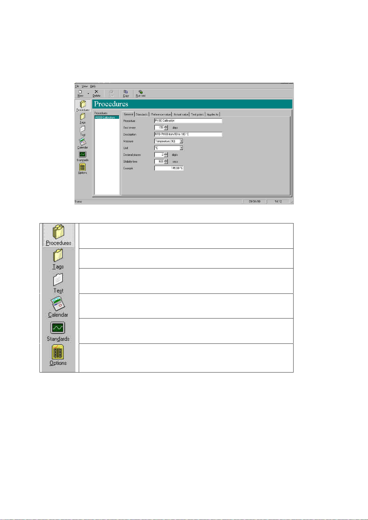
All program options are available using the main menu bar. The button functions are the following:
This option allows you to program the calibration procedure. You can input all general
information, instruments used as standards, calibrators used as simulator and as
reader, test points and error limits, Tags.
This option allows you to add, delete, modify all Tag’s information: name,
Manufacturer, model, S/N, and applied calibration procedure.
This option allows you to review and print calibration procedure results database.
This option shows the calibration due date for all Tags. When you calibrate the
instrument, the date will be changed by the software for the new expiration date.
This option allows you to set all information about instruments used as reference in
calibration activities.
This option allows you to edit al header and footer for your calibration reports
2.1 Calibration Procedures
This is the core of CalpMan 2000 (CL550-SOFT). Using this option, you can program all data for a new calibration
procedure.
6
Page 7

Create a new procedure is easy by pressing the button and selecting the “Procedure” option.
The procedure windows will be displayed. All fields assumes the pre-set values. You can modify procedure data for
compliance with your testing procedure.
Edit a procedure is possible by selecting the procedure name and changing the values directly on the windows. All
changes will be stored automatically in the PC hard-disk.
Deleting a procedure is possible by selecting the procedure name and pressing the button.
The procedures data are divided into 6 forms: General, Standards, Reference value, Actual value, Test points, and
Applies to.
GENERAL: The procedure main information should be inserted in this form: Procedure name and
description, calibration validity period (this value will be used by CalpMan to update the
calibration due date for the Tag), type of measurements (Pressure, Frequency,
Temperature, current, etc.), engineering unit, number of decimals, stability time (the
procedure will wait for this time before make the measurement from Tag).
STANDARDS: Up to 4 external standards units can be assigned to each procedure. This units will be
printed on your calibration reports. You can select between the available in “Standards”
option (see paragraph 2.5).
7
Page 8

REFERENCE VALUE: This form allows you to define how the reference values can be input by program:
Manual or automatic (by calibrator) mode.
In manual input mode, the reference values are input by typing the values using the
keyboard. This operative mode can be used when the calibrator used is not an OMEGA
unit.
In calibrator input mode, the reference values are read by an OMEGA calibrator using the
RS232 serial interface. Select the used unit and the communication parameters. The
“calibrator function” mode can be selected program the unit as generator or as meter.
ACTUAL VALUE: This form allows you to define how the actual values (measured from the tag) can be
input by program: Manual or automatic (by calibrator) mode.
In manual input mode, the actual values are input by typing the values using the
keyboard. This operative mode can be used when the Tag used is not an OMEGA unit.
In calibrator input mode, the actual values are read by an OMEGA unit using the RS232
serial interface. Select the used unit and the communication parameters. The “calibrator
function” mode can be selected program the unit as generator or as meter. If meter
mode is selected, you can choose to read the data directly or linearized (e.g. 4-20mA to
0-100mbar).
TEST POINTS: This form allows you to program all procedure test points and limits of errors. Input all
test points values, then choose for full scale error or for of reading error input. Two kind
of error can be input: Reference error and Actual error.
Reference error is the maximum error band for the generated values. The Procedure will
not accepted the generated value if it is outside the band.
Actual error is the maximum error band for the measured values. The Procedure will
mark the value as fault if it is outside the band.
8
Page 9

Press “Generate Error Data” button to calculate the error limits.
APPLIES TO: This form allows you to input the Tags to be assigned to the calibration procedure. You
can input the following information: Name, Manufacturer, Model and S/N. When you
insert a new Tag to the procedure, the calibration due date will be automatically set to
the currency day.
You can also add a new Tag using the “New Tag” function in “Tag” option.
2.2 Tags
This option allows to edit all entered Tag information. You can read all units information and the procedure assigned.
If no test procedure was performed for the Tag, you can modify all parameters. If a Test procedure was done, you cannot
change the assigned calibration procedure.
9
Page 10

To delete a Tag, you have to select it using the mouse and then pressing the button.
2.3 Test
This option allows you to browse the previous testing data and to run a new test procedure. The column on the left of the
window shows the Tags list. Choosing one Tag from list, it will be shown (if existing) the performed tests ordered by date.
To perform a new test procedure, you have to select the Tag and then to press the button. The following
window will be displayed:
Make all electrical connections and connect, if programmed, the RS232 connection cables. Press the “OK” button to run
the procedure.
If RS232 serial communication is programmed for Tag and Reference units, you have only to wait for procedure ends.
The following monitor windows will be displayed:
10
Page 11

If manual values input is programmed the program will ask for the reference and the actual values.
When all data are entered (or the automatic procedure terminate), the program will show you for the calibration results.
A red line will highlight you for procedure error.
A Yellow line will inform you for a wrong result.
A white line will inform you for a good result.
You can preview the testing report by selecting the “File – Print preview” option. And print it by pressing the button.
Another features is the possibility to insert a bitmap file (e.g. with your logo) on the report. If you save your image file
using the name “header.bmp” in CalpMan 2000 main directory, this image will be printed below the Report Header.
11
Page 12

2.4 Calendar
This option views the certification due date for each entered Tag ordered by date. If a Tag certification is expired, its
description line is highlighted using red characters.
You can select the desired Tag and run the testing procedure by pressing the button.
2.5 Standards
This option allows you to manage the Standard units database. You can add, delete, or modify the data for the reference
instruments used for the procedure. You can enter many important information: Model, S/N, internal reference, notes,
OMEGA model, Manufacturer, and next calibration date. Next calibration date field, is very important because allows you
to manage the calibration due date for your standards: the red characters will inform you that a new calibration should be
performed.
2.6 Options
This option allows you to edit Report and Page Headers and Footers for documentation printing. Each certification of
calibration can be personalized with your name, address or with a document introduction.
12
Page 13

2.7 Exit
By selecting this option on the File menu, you can quit CalPMan 2000 software.
13
Page 14

3 APPLICATIONS
RS232 COM2
connection
Typical procedures to check and certificate the most common instruments are shown in the following paragraphs.
IMPORTANT: THE FOLLOWING PARAGRAPH IS ONLY TO SHOW HOW THE PROGRAM WORKS. THE DATA ARE INDICATIVE FOR THE
DESCRIBED EXAMPLE.
3.1 Rtd certification
The application consists to certificate a resistance thermometer (Pt01) using the system described below. CalpMan 2000
(CL550-SOFT) package is designed to work with all OMEGA calibration instruments. As example we have choose to use
CL526 multifunction calibrator for Rtd temperature reading and CL551 dry block temperature calibrator for temperature
generation.
We need the following components:
§ A Personal Computer with two RS232 board (we recommend a Pentium or equivalent processor)
§ CalpMan 2000 (CL550-SOFT) software.
§ OMEGA CL551 or other OMEGA temperature calibrator completed of a multiple hole insert block.
§ OMEGA CL526 signal calibrator with RS232 communication cable.
§ The Rtd to be certified.
Connect all system components and the Rtd to be certified as follows:
RS232 COM1
Rtd
CL551
CL526
• Connect the RS232 serial communication cables among the PC and the instruments.
• Insert the resistance thermometer in CL551 dry block.
• Connect the Rtd to the CL526.
• Switch the instruments and the Personal Computer on.
Rtd specifications are:
• Model: Pt100 3w produced by UKB S.r.l.
• Tag name: Pt-01-123
• Resistance thermometer type Pt100 3-wires
• Measuring range: 30…120°C
• S/N: 97I13/04
• Certification temperature test point:
50°C max error ±1.0°C
100°C max error ±1.0°C
3 wire Pt100
Run the CalPMan 2000 calibration package.
14
Page 15

3.1.1 Standards programming
Before starting procedure programming, you have to input the data of the instruments used as Standards in calibration
procedure.
Press “Standards” menu button on the vertical menu bar.
Add the following two records for CL526 and CL551 calibrators in database table.
3.1.2 Procedure programming
Press “Procedures” menu button on the vertical menu bar.
Create a new procedure is easy by pressing the button and selecting the “Procedure” option.
The procedure windows will be displayed. All fields assumes the pre-set values. You can modify procedure data for
compliance with your testing procedure.
GENERAL
The procedure main information should be inserted in this form.
Program the form as following:
Procedure: Pt100 Calibration
Test every: 150 days
Description: RTD certification Pt100 3w from 50 to 100°C
Measure: Temperature (90)
Unit: °C
Decimal places: 2 digits
Stability time: 600 secs
STANDARDS
15
Page 16

This form allows you to define up to 4 external standards to be assigned to the procedure. We don’t have any external
standards: all field have to be set to “none”.
REFERENCE VALUE
This form allows you to define how the reference values can be input by program: Manual or automatic (by calibrator)
mode.
Program the form as following:
Manual/Calibrator: Calibrator
Standard: TCAL012 (CL550 /551)
Version: 1
COM Port: COM1
Baud Rate: 9600
Temperature: Furnace (RJ int.)
Calibration function: Generate
ACTUAL VALUE
This form allows you to define how the actual values (measured from the tag) can be input by program: Manual or
automatic (by calibrator) mode.
Program the form as following:
Manual/Calibrator: Calibrator
Standard: UCAL 023 (CL526)
Version: 4
COM Port: COM2
Baud Rate: 9600
Temperature: RTD 3 wires
RTD Type: Pt100 (.385)
Calibration function: Measure
Input type: Direct
TEST POINTS
This form allows you to program all procedure test points and error limits. Enter data as following:
APPLIES TO
This form allows you to input the Tags to be assigned to the calibration procedure.
16
Page 17

3.1.3 Run the procedure
To perform a new test procedure, you have to select the Tag and press the button. The following window will be
displayed:
Check all electrical connections. Press the “OK” button to run the procedure. The following window will be displayed:
When all test point will be performed, it will be shown the calibration result.
A red line will highlight you for procedure error.
A Yellow line will inform you for a wrong result.
A white line will inform you for a good result.
3.1.4 Print the test results
Press “Test” menu button on the vertical menu bar.
17
Page 18

Select the Tag by the list; select the procedure you have to view and/or print.
You can preview the certificate by selecting the “File – Print preview” option.
You can print the certificate by pressing the button.
18
Page 19

WARRANTY/DISCLAIMER
FOR WARRANTY RETURNS, please has the
FOR NON-WARRANTY REPAIRS, consult OMEGA for
OMEGA ENGINEERING, INC. warrants this unit to be free of defects in materials and workmanship for a period of 13
months from date of purchase. OMEGA Warranty adds an additional one (1) month grace period to the normal one (1)
year product warranty to cover handling and shipping time. This ensures that OMEGA’s customers receive maximum
coverage on each product.
If the unit should malfunction, it must be returned to the factory for evaluation. OMEGA’s Customer Service Department
will issue an Authorized Return (AR) number immediately upon phone or written request. Upon examination by OMEGA,
if the unit is found to be defective it will be repaired or replaced at no charge. OMEGA’s WARRANTY does not apply to
defects resulting from any action of the purchaser, including but not limited to mishandling, improper interfacing,
operation outside of design limits, improper repair, or unauthorized modification. This WARRANTY is VOID if the unit
shows evidence of having been tampered with or shows evidence of being damaged as a result of excessive corrosion;
or current, heat, moisture or vibration; improper specification; misapplication; misuse or other operating conditions
outside of OMEGA’s control. Components which wear are not warranted, including but not limited to contact points,
fuses, and triacs.
OMEGA is pleased to offer suggestions on the use of its various products However, OMEGA neither assumes
responsibility for any omissions or errors nor assumes liability for any damages that result from the use of its
products in accordance with information provided by OMEGA, either verbal or written. OMEGA warrants only
that the parts manufactured by it will be as specified and free of defects. OMEGA MAKES NO OTHER WARRANTIES OR REPRESENTATIONS OF ANY KIND WHATSOEVER, EXPRESSEO OR IMPUED, EXCEPT THAT OF
TITLE, AND ALL IMPLIED WARRANTlES INCLUDING ANY WARRANTY OF MERCHANTABIUTY AND RTNESS
FOR A PARTICULAR PURPOSE ARE HEREBY DISCLAIMED. LIMITATION OF LIABILITY: The remedies of
purchaser set forth herein ate exclusive and the total liability of OMEGA with respect to this order, whether
based on contract, warranty, negligence. Indemnification, strict liability or otherwise, shall not exceed the
purchase price of the component upon which liability is based. In no event shall OMEGA be liable for
consequential, incidental or special damages.
CONDITIONS: Equipment sold by OMEGA is not intended to be used, nor shall it be used: (1) as a ”Basic Component”
under 10 CFR 21 (NRC), used in or with any nuclear installation or activity; or (2) in medical applications or used on
humans. Should any Product(s) be used in or with any nuclear installation or activity, medical application, used on
humans, or misused in any way, OMEGA assumes no responsibility as set forth in our basic WARRANTY/DISCLAIMER
language, and additionally, purchaser will indemnify OMEGA and hold OMEGA harmless from any liability or damage
whatsoever arising out of the use of the Product(s) in such a manner.
RETURN REQUESTS / INQUIRIES
Direct all warranty and repair requests/inquiries to the OMEGA Customer Service Department. BEFORE RETURNING
ANY PRODUCT(S) TO OMEGA, PURCHASER MUST OBTAIN AN AUTHORIZED RETURN (AR) NUMBER FROM
OMEGA’S CUSTOMER SERVICE DEPARTMENT (IN ORDER TO AVOID PROCESSING DELAYS). The assigned AR
number should then be marked on the outside of the return package and on any correspondence.
The purchaser is responsible for shipping charges, freight, insurance and proper packaging to prevent breakage in
transit.
following information available BEFORE contacting
OMEGA:
1. P.O. number under which the product was
PURCHASED,
2. Model and serial number of the product under
warranty, and
3. Repair instructions and/or specific problems
relative to the product.
current repair charges. Have the following information
available BEFORE contacting OMEGA:
1. P.O. number to cover the COST of the repair,
2. Model and serial number of product, and
3. Repair instructions and/or specific problems relative to
the product.
OMEGA’s policy is to make running changes, not model changes, whenever an improvement is possible. This affords our customers the
latest in technology and engineering.
OMEGA is a registered trademark of OMEGA ENGINEERING, INC.
(C) Copyright 1999 OMEGA ENGINEERING, INC. All rights reserved. This document may not be copied, photocopied, reproduced,
translated, or reduced to any electronic medium or machine-readable form, in whole or in part, without prior written consent of OMEGA
ENGINEERING, INC.
19
Page 20

Where Do I Find Everything I Need for
Process Measurement and Control?
OMEGA…Of Course!
TEMPERATURE
RR Thermocouple, RTD & Thermistor Probes, Connectors, Panels & Assemblies
RR Wire: Thermocouple, RTD & Thermistor
RR Calibrators & Ice Point References
RR Recorders, Controllers & Process Monitors
RR Infrared Pyrometers
PRESSURE, STRAIN AND FORCE
RR Transducers & Strain Gauges
RR Load Cells & Pressure Gauges
RR Displacement Transducers
RR Instrumentation & Accessories
FLOW/LEVEL
RR Rotameters, Gas Mass Flowmeters & Flow Computers
RR Air Velocity Indicators
RR Turbine/Paddlewheel Systems
RR Totalizers & Batch Controllers
pH/CONDUCTIVITY
RR pH Electrodes, Testers & Accessories
RR Benchtop/Laboratory Meters
RR Controllers, Calibrators, Simulators & Pumps
RR Industrial pH & Conductivity Equipment
DATA ACQUISITION
RR Data Acquisition & Engineering Software
RR Communications-Based Acquisition Systems
RR Plug-in Cards for Apple, IBM & Compatibles
RR Datalogging Systems
RR Recorders, Printers & Plotters
HEATERS
RR Heating Cable
RR Cartridge & Strip Heaters
RR Immersion & Band Heaters
RR Flexible Heaters
RR Laboratory Heaters
ENVIRONMENTAL MONITORING AND CONTROL
RR Metering & Control Instrumentation
RR Refractometers
RR Pumps & Tubing
RR Air, Soil & Water Monitors
RR Industrial Water & Wastewater Treatment
RR pH, Conductivity & Dissolved Oxygen Instruments
20
 Loading...