

Page 1

http://www.omega.com
y
e-mail: info@omega.com
CL524 & CL525
2 channel High Accurac
Multifunction Calibrators
Page 2

OMEGAnetSM On-Line Service
Internet e-mail
http://www.omega.com
info@omega.com
Servicing North America:
USA:
ISO 9001 Certified
Canada:
One Omega Drive, Box 4047
Stamford, CT 06907-0047
Tel: (203) 359-1660
e-mail: info@omega.com
976 Bergar
Laval (Quebec) H7L 5A1
Tel: (514) 856-6928
e-mail: info@omega.ca
FAX: (203) 359-7700
FAX: (514) 856-6886
For immediate technical or application assistance:
Usa and Canada:
Mexico and
Latin America:
Sales Service: 1-800-826-6342 / 1-800-TC-OMEGA
Customer Service: 1-800-622-2378 / 1-800-622-BEST
Engineering Service: 1-800-872-9436 / 1-800-USA-WHEN
TELEX: 996404 EASYLINK: 62968934 CABLE: OMEGA
Tel: (95) 800-826-6342
En Español: (95) 203-359-7803
e-mail: espanol@omega.com
SM
SM
SM
FAX: (95) 203-359-7807
Servicing Europe:
Benelux:
Czech Republic:
France:
Germany/Austria:
United Kingdom:
ISO 9002 Certified
It is the policy of OMEGA to comply with all worldwide safety and EMC/EMI regulations that apply. OMEGA is constantly
pursuing certification of its products to the European New Approach Directives. OMEGA will add the CE mark to every
appropriate device upon certification.
The information contained in this document is believed to be corrected but OMEGA Engineering Inc. accepts no liability for any errors it
WARNING: These products are not designed for use in, and should not be used for, patient connected applications.
Postbus 8034, 1180 LA Amstelveen, The Netherlands
Tel: (31) 20 6418405
Toll Free in Benelux: 0800 0993344
e-mail: nl@omega.com
ul. Rude armady 1868, 733 01 Karvina-Hranice, Czech Republic
Tel: 420 (69) 6311899
Toll free: 0800-1-66342
e-mail: czech@omega.com
9, rue Denis Papin, 78190 Trappes
Tel: (33) 130-621-400
Toll Free in France: 0800-4-06342
e-mail: france@omega.com
Daimlerstrasse 26, D-75392 Deckenpfronn, Germany
Tel: 49 (07056) 3017
Toll Free in Germany: 0130 11 21 66
e-mail: info@omega.de
One Omega Drive , River Bend Technology Centre
Northbank, Irlam, Manchester
M44 5EX, England
Tel: 44 (161) 777-6611
Toll Free in United Kingdom: 0800-488-488
e-mail: info@omega.co.uk
contains, and reserves the right to alter specifications without notice.
FAX: (31) 20 6434643
FAX: 420 (69) 6311114
FAX: (33) 130-699-120
FAX: 49 (07056) 8540
FAX: 44 (161) 777-6622
2
Page 3

INTRODUCTORY NOTE
This manual has been with all the information you need to install, operate and maintain the 2 channels
multifunction calibrator CL520 series and its accessories.
OMEGA has used the best care and efforts in preparing this book and believes the information in this
publication are accurate. The OMEGA products are subjected to continuous improvement, in order to pursue
the technological leadership; these improvements could require changes to the information of this book.
OMEGA reserves the right to change such information without notice.
No part of this document may be stored in a retrieval system, or transmitted in any form, electronic or
mechanical, without prior written permission of OMEGA Engineering, inc..
CL520 series multifunction calibrator uses sophisticated analogic and digital technologies. Any maintenance
operation must be carried out by qualified personnel
ONLY. OMEGA supplies instructions and operative
procedures for any operation on the instrument. We recommend to contact our technicians for any support
requirements.
CL520 series is fully tested in conformity with the directive n°89/336/CEE Electromagnetic Compatibility.
OMEGA shall not be liable in any event, technical and publishing error or omissions, for any incidental and
consequential damages, in connection with, or arising out of the use of this book.
3
Page 4

TABLE OF CONTENTS
1 PERFORMANCE.................................................................................................................................. 6
1.2 Specifications ................................................................................................................................................... 7
1.3 Table of ranges and accuracy .......................................................................................................................... 8
2 GENERAL FEATURES........................................................................................................................ 9
2.1 Innovative design ............................................................................................................................................. 9
2.2 Flexibility .......................................................................................................................................................... 9
2.3 Keyboard - Display........................................................................................................................................... 9
2.4 Digital interface ................................................................................................................................................9
2.5 Firmware .......................................................................................................................................................... 9
2.6 Scale factor - Square root ................................................................................................................................9
2.7 Cold Junction compensation ..........................................................................................................................10
2.8 Calculated readings .......................................................................................................................................10
2.9 Transmitter simulation and calibration............................................................................................................ 10
2.10 Frequency - Counts........................................................................................................................................ 10
2.11 Programmable signal converter .....................................................................................................................10
2.12 Resistance thermometer ................................................................................................................................10
2.13 Remote temperature probe ............................................................................................................................ 10
2.14 Graphic mode................................................................................................................................................. 10
2.15 Simulation programs ...................................................................................................................................... 10
2.16 Power supply.................................................................................................................................................. 11
2.17 Report of Calibration ...................................................................................................................................... 11
2.18 CL520-CPS Software - Documents calibration data ...................................................................................... 11
2.19 CL520-LGM Software for data acquisition ..................................................................................................... 11
2.20 CL520-SLS Software for special linearizations .............................................................................................. 11
3 PHYSICAL DESCRIPTION................................................................................................................ 12
4 FUNCTIONAL DESCRIPTION........................................................................................................... 13
4.1 Power supply.................................................................................................................................................. 13
4.2 Keyboard........................................................................................................................................................ 14
4.3 Input circuit..................................................................................................................................................... 14
4.4 Microcontroller................................................................................................................................................ 15
4.5 Firmware ........................................................................................................................................................ 15
4.6 Display ........................................................................................................................................................... 15
4.7 Digital to analog converter ............................................................................................................................. 16
4.8 External battery charger or mains line operation............................................................................................ 16
4.9 Digital interface ..............................................................................................................................................17
4.10 Resistance and RTD measurements ............................................................................................................. 17
4.11 Resistance and RTD simulation ..................................................................................................................... 17
4.12 Thermocouples input/output circuit ................................................................................................................ 17
5 PRE-OPERATIONAL CHECK ........................................................................................................... 19
5.1 Unpacking ......................................................................................................................................................19
5.2 Case............................................................................................................................................................... 19
5.2.1 Portable cases........................................................................................................................................... 19
5.2.2 Panel mounting .........................................................................................................................................19
5.2.3 Table top use............................................................................................................................................. 19
6 POWER SUPPLY............................................................................................................................... 20
6.1 Power supply.................................................................................................................................................. 20
6.1.1 Rechargeable battery ................................................................................................................................ 20
6.1.2 Charging the battery.................................................................................................................................. 20
6.1.3 How to maximize the life span of the battery............................................................................................. 20
7 ELECTRICAL CONNECTIONS ......................................................................................................... 21
7.1 Wiring practice ...............................................................................................................................................21
7.2 Thermocouple wires....................................................................................................................................... 22
7.3 Remote connections ...................................................................................................................................... 22
7.3.1 External contact......................................................................................................................................... 22
7.3.2 Remote Rj ................................................................................................................................................. 23
8 OPERATION & APPLICATIONS....................................................................................................... 24
8.1 Power ON ...................................................................................................................................................... 24
8.2 Configuration Reset ....................................................................................................................................... 25
8.3 Next Calibration date...................................................................................................................................... 25
8.4 Display adjustments ....................................................................................................................................... 25
8.4.1 Display backlight .......................................................................................................................................25
8.4.2 Autolamp mode ......................................................................................................................................... 26
4
Page 5

8.5 "Help" key....................................................................................................................................................... 26
8.6 Configuration review (Status)......................................................................................................................... 26
8.7 General configuration set-up.......................................................................................................................... 29
8.8 Slot display swapping..................................................................................................................................... 30
8.9 Channels scrolling.......................................................................................................................................... 31
8.10 Decimal point position .................................................................................................................................... 31
8.11 Average mode................................................................................................................................................ 31
8.12 Autorange ...................................................................................................................................................... 31
8.13 Alarm function ................................................................................................................................................ 31
8.14 Parameter or sensor selection .......................................................................................................................32
8.15 Scale factor mode set-up ............................................................................................................................... 33
8.16 Temperature parameters selection ................................................................................................................ 34
8.17 Rj fast mode selection.................................................................................................................................... 35
8.18 Resistance thermometer selection ................................................................................................................. 35
8.19 IN-OUT data memories .................................................................................................................................. 36
8.20 Autoscan program mode................................................................................................................................ 36
8.21 Ramp program mode ..................................................................................................................................... 36
8.22 Bargraph function........................................................................................................................................... 37
8.23 Switch test routine.......................................................................................................................................... 38
8.24 Offset mode set-up......................................................................................................................................... 40
8.25 Frequency IN - OUT...................................................................................................................................... 40
8.25.1 Frequency OUT........................................................................................................................................ 40
8.25.2 Frequency IN............................................................................................................................................ 40
8.26 Transmitter simulation.................................................................................................................................... 41
8.27 Graphic operative mode................................................................................................................................. 42
8.28 Pulse IN-OUT................................................................................................................................................. 42
8.28.1 Pulse generation ....................................................................................................................................... 42
8.28.2 Pulse frequency measurement and counter mode.................................................................................... 43
8.29 Percentage and error displays .......................................................................................................................45
9 OPTIONS & ACCESSORIES............................................................................................................ 47
9.1 External printer............................................................................................................................................... 47
9.1.1 General recommendation .......................................................................................................................... 47
9.1.2 Printer operations: General .......................................................................................................................47
9.1.3 Printer operation: Normal In-Out mode ..................................................................................................... 48
9.2 Data Logging function .................................................................................................................................... 48
9.2.1 Printout of memory stored date .................................................................................................................51
9.3 RAM card ....................................................................................................................................................... 52
10 DIGITAL INTERFACE........................................................................................................................ 53
10.1 Digital output wiring practice...................................................................................................................... 53
10.2 Communication protocol ................................................................................................................................ 54
10.2.1 Computer data request from CL520 series................................................................................................54
10.2.2 Computer data setting from PC ................................................................................................................. 60
11 MAINTENANCE ................................................................................................................................. 64
11.1 Faulty operating conditions ........................................................................................................................... 64
11.2 Protection fuses replacement......................................................................................................................... 64
11.3 Safety recommendations ............................................................................................................................... 65
11.4 Accessories & Spare parts............................................................................................................................. 65
11.5 Storage .......................................................................................................................................................... 65
5
Page 6

1 PERFORMANCE
A fundamental tool to monitor quality assurance test equipment as required by ISO 9000 and to mantain the traceability
in accordance with National Standards.
The indicator-simulator CL524 and CL525 are high accuracy multifunction instruments, with 2 isolated and independent
channels, designed to meet the needs of instrumentation engineers, both in laboratory and in field work.
Accurate, compact, rugged, easy to use; the ideal solution to measure and simulate:
Both Channel 1 (In) and Channel 2 (Out) have the following operative mode capability:
• millivolts
• volts
• milliamperes (active and passive loop)
• ohms
• temperature with thermocouples
• temperature with resistance thermometers
• frequency
• pulse and counter
Remote auxiliary inputs are available for :
• Relative humidity and temperature
(the temperature sensor uses the same input of the remote cold junction sensor. The above inputs are non isolated
from the "Out" channel)
CL520 series calibrators have been developed using the most advanced A/D conversion and a fast and powerful 32 bit
microcontroller to provide high accuracy on extended ranges and a powerful operative flexibility. The firmware is stored
in a flash memory to allow future upgrade directly from serial interface using a floppy disk in a Personal Computer
• All normalized IEC, DIN, JIS thermocouples
• Pt, Ni, Cu resistance thermometers, temperature measurement and active simulation with a proprietary circuit
(patent n. 206327).
• mA, mV, V,
• IPTS 68 and ITS 90 selection directly through keyboard
• Current INput/OUTput mode directly on active or passive loops
• Rechargeable Ni-Cd battery and line operations
• Bidirectional digital interface
• Portable, table top and panel mounting
• Report of Calibration
The CL525 has an improved performance and accuracy, is equipped with a PCMCIA Memory Card and with a
communication bus for an extension with pressure or optional modules.
Ω, frequency, pulse
6
Page 7

1.2 Specifications
• IN/OUT parameters:
Signal type
thermocouples type
resistance thermometers
• Reference junction compensation:
internal automatic
external adjustable
remote with external Pt100
• Rj compensation drift: ±0.015°C/°C (from -10 °C to +55 °C)
• Common mode rejection: >140 dB at ac operation
• Normal mode rejection: >60 dB at 50 or 60 Hz
• Temperature stability:
full scale
zero
• Output impedance (emf output): less than 0.5 ohm with a maximum current of 0.5 mA
• Input impedance (mV, V and Tc ranges): >10 M Ω
• Input impedance (mA ranges): <130 Ω at 1 mA
• Source resistance effects: ±1 µV error for 1000 ohms source resistance
• RTD and Ω simulation excitation current: from 0.1 to 2 mA
• RTD and Ω measurement excitation current: 0.4 mA
• RTD terminals: 2, 3 or 4 wires
• RTD cable compensation: up to 100 Ω (for each wire)
• RTD cable compensation error (Pt100): ±0.005°C/ Ω of total wire
• Maximum load resistance: 1000 Ω at 20 mA
• Display: graphic LCD 240 x 64 dots display with backlight device
• Measurement sampling time: 250 ms
• Output noise (at 300 Hz): <2 µVpp for ranges up to 200 mV f.s., <10 µVpp for ranges up to 2000 mV f.s. and
<80 µVpp for ranges up to 20 V f.s.
• Digital interface: full bi-directional TTL (a RS232 adapter normal or insulated, is available as an option)
• Channel 1-Channel 2 insulation: 250 Vdc
• Calculation functions: hold, max, min, offset, average
• Simulation mode: in-line single digit setting, numerical entry, memory loaded value, autostep, autoramp,
autoscan, autocycle
• Selection °C/°F/K: through the configuration procedure
• Convert function: displays the electrical equivalent of the engineering unit
• Scale factor: 5 setting with zero and span programmable within -399999 and +999999
• Square root: in combination with scale factor
• Calibration: self learning technique with automatic procedure
• Logging mode: >1500 input data items (optional memory card for memory extension)
• In/Out data memory: 20 data with manual or automatic recall
• Power supply: external charger and rechargeable Ni-Cd battery
• Self contained operation:
6 h on Tc and mV input/output (backlight Off)
3.5 h with 20 mA simulation (backlight Off)
• Recharging time: 5 h at 90% and 6 h at 99% with instrument switched off. The battery recharge is active only
with the instrument switched off.
• Battery charge indication: bar graph on the LCD display
• Line operation: 100V - 115 V - 230V Vac through the external battery charger
• Line transformer insulation: 2500 Vac
• Firmware release identification: release code on the display
• Operating environment temperature range: from -10 °C to +55 °C
• Storage temperature range: from -30 °C to +60 °C
• Case: Injection molded ABS
• Dimensions: 264 x 96 x 172 mm (DIN size)
• Weights: net 4 Kg gross 5.5 Kg
mV, V, mA, Ω, K Ω, frequency, pulses
J, K, T, R, S, B, N, C, E, U, L, F, G, D
Pt100 IEC, OIML, USLAB, US, SAMA, JIS Pt200, 500, 1000, 1000 OIML, Ni100,
Ni120, Cu10, Cu100
from -10 °C to +55 °C
from -50 °C to +100 °C
from -10°C to +100 °C
: ± 8 ppm/°C
: ± 0.2 µV /°C
7
Page 8

1.3 Table of ranges and accuracy
IN-OUT RANGES
CL525 CL524
Sensor or Total range Accuracy range Resolution Accuracy Accuracy
parameter (% of reading) (% of reading)
Tc type J -210 to 1200°C -190 to 1200°C 0.1°C ±(0.01% +0.1°C) ± (0.02% +0.1 °C)
-350 to 2200°F -310 to 2192°F 0.1°F ±(0.01% +0.18F) ± (0.02% +0.18 °F)
Tc type K -270 to 1370°C -160 to 1260°C 0.1°C ±(0.01% +0.1°C) ± (0.02% +0.1 °C)
454 to 2500°F -256 to 2300°F 0.1°F ±(0.01% +0.18°F) ± (0.02% +0.18 °F)
Tc type T -270 to 400°C -130 to 400°C 0.01°C ±(0.01% +0.1°C) ± (0.02% +0.1 °C)
-454 to 760°F -238 to 752°F 0.1°F ±(0.01% +0.18°F) ± (0.02% +0.18 °F)
Tc type R -50 to 1760°C 150 to 1760°C 0.1°C ±(0.01% +0.2°C) ± (0.02% +0.2 °C)
-60 to 3200°F 302 to 3200°F 0.1°F ±(0.01% +0.36°F) ± (0.02% +0.36 °F)
Tc type S -50 to 1760°C 170 to 1760°C 0.1°C ±(0.01% +0.2°C) ± (0.02% +0.2 °C)
-60 to 3200°F 338 to 3200°F 0.1°F ±(0.01% +0.36°F) ± (0.02% +0.36 °F)
Tc type B 50 to 1820°C 920 to 1820°C 0.1°C ±(0.01% +0.3°C) ± (0.02% +0.3 °C)
140 to 3310°F 1688 to 3308°F 0.1°F ±(0.01% +0.54°F) ± (0.02% +0.54 °F)
Tc type C 0 to 2300°C 0 to 2000°C 0.1°C ±(0.01% +0.2°C) ± (0.02% +0.2 °C)
32 to 4180°F 32 to 3632°F 0.1°F ±(0.01% +0.36°F) ± (0.02% +0.36 °F)
Tc type G 0 to 2300°C 190 to 2300°C 0.1°C ±(0.01% +0.3°C) ± (0.02% +0.3 °C)
32 to 4180°F 374 to 4172°F 0.1°F ±(0.01% +0.54°F) ± (0.02% +0.54 °F)
Tc type D 0 to 2300°C 0 to 2130°C 0.1°C ±(0.01% +0.3°C) ± (0.02% +0.3 °C)
32 to 4180°F 32 to 3866°F 0.1°F ±(0.01% +0.54°F) ± (0.02% +0.54 °F)
Tc type U -200 to 400°C -160 to 400°C 0.1°C ±(0.01% +0.1°C) ± (0.02% +0.1 °C)
-330 to 760°F -256 to 752°F 0.1°F ±(0.01% +0.18°F) ± (0.02% +0.18 °F)
Tc type L -200 to 760°C -200 to 760°C 0.1°C ±(0.01% +0.1°C) ± (0.02% + 0.1 °C)
-330 to 1400°F -328 to 1400°F 0.1°F ±(0.01% +0.18°F) ± (0.02% +0.18 °F)
Tc type N -270 to 1300°C 0 to 1300°C 0.1°C ±(0.01% +0.1°C) ± (0.02% +0.1 °C)
-450 to 2380°F 32 to 2372°F 0.1°F ±(0.01% +0.18°F) ± (0.02% +0.18 °F)
Tc type E -270 to 1000°C -200 to 1000°C 0.1°C ±(0.01% +0.1°C) ± (0.02% +0.1 °C)
-454 to 1840°F -328 to 1832°F 0.1°F ±(0.01% +0.18°F) ± (0.02% +0.18 °F)
Tc type F 0 to 1400°C 0 to 1400°C 0.1°C ±(0.01% +0.1°C) ± (0.02% +0.1 °C)
32 to 2560°F 32 to 2552°F 0.1°F ±(0.01% +0.18°F) ± (0.02% +0.18 °F)
Pt100 IEC -200 to 850°C -200 to 850°C 0.01°C ±(0.01% +0.05°C) ± (0.02% +0.05 °C)
OIML, a 3926 -330 to 1570°F -328 to 1562 °F 0.1°F ±(0.01% +0.09°F) ± (0.02% +0.09 °F)
Pt100 -200 to 650°C -200 to 650°C 0.01°C ±(0.01% +0.05°C) ± (0.02% +0.05 °C)
a 3902 -330 to 1210°F -328 to 1210°F 0.1°F ±(0.01% +0.09°F) ± (0.02% +0.09 °F)
Pt100 JIS -200 to 600°C -200 to 600°C 0.01°C ±(0.01% +0.05°C) ± (0.02% +0.05 °C)
SAMA -330 to 1120°F -328 to 1112°F 0.1°F ±(0.01% +0.09°F) ± (0.02% +0.09 °F)
Pt 200 -200 to 850°C -200 to 850°C 0.1°C ±(0.01% +0.15°C) ± (0.02% +0.15 °C)
-330 to 1570°F -328 to 1562°F 0.1°F ±(0.01% +0.27°F) ± (0.02% +0.27 °F)
Pt 500 -200 to 850°C -200 to 530°C 0.1°C ±(0.01% +0.1°C) ± (0.02% +0.1 °C)
-330 to 1570°F -328 to 986°F 0.1°F ±(0.01% +0.18°F) ± (0.02% +0.18 °F)
Pt1000 IEC -200 to 850°C -200 to 850°C 0.01°C ±(0.01% +0.1°C) ± (0.02% +0.1 °C)
OIML -330 to 1570°F -328 to 1562°F 0.1°F ±(0.01% +0.18°F) ± (0.02 % +0.18 °F)
CU10 -70 to 150°C -70 to 150°C 0.1°C ±(0.01% +0.4°C) ± (0.02% +0.4 °C)
-100 to 310°F -94 to 302°F 0.1°F ±(0.01% +0.72°F) ± (0.02% +0.72 °F)
CU100 -180 to 150°C -180 to 150°C 0.1°C ±(0.01% +0.05°C) ± (0.02% +0.05 °C)
-300 to 310°F -292 to 302°F 0.1°F ±(0.01% +0.09°F) ± (0.02% +0.09 °F)
Ni100 -60 to 180°C -60 to 180°C 0.1°C ±(0.01% +0.05°C) ± (0.02% +0.05 °C)
-80 to 360°F -76 to 356°F 0.1°F ±(0.01% +0.09°F) ± (0.02% +0.09 °F)
Ni120 0 to 150°C 0 to 150°C 0.1°C ±(0.01% +0.05°C) ± (0.02% +0.05 °C)
32 to 310°F 32 to 302°F 0.1°F ±(0.01% +0.09°F) ± (0.02% +0.09 °F)
mV -20 to +200mV 1µV ±(0.01% +2µV) ± (0.02% +2 µV)
mV -0.2 to +2 V 10 µV ±(0.01% +10 µV ± (0.02% +10 µV)
V -2 to +20 V 0.1mV ±(0.01% +0.08mV) ± (0.02% +0.08 mV)
mA (In) -5 to +50mA 0.1µA ±(0.01% +0.4µA) ± (0.02% +0.4 µA)
mA (Out) 0 to +50mA 0.1µA ±(0.01% +0.4µA) ± (0.02% +0.4 µA)
Ω IN 0 to 500Ω 1mΩ ±(0.01% +12mΩ) ± 0.02% +12 mΩ)
0 to 5000 Ω 0.01Ω ±(0.01% +120mΩ) ± (0.02% +120 mΩ)
Ω OUT 0 to 500 Ω 1 mΩ ±(0.01% +20mΩ) ± (0.02% +20 mΩ)
0 to 5000 Ω 0.01Ω ±(0.01% +200mΩ) ± (0.02% +200 mΩ)
Frequency 1 to 200 Hz 0.001 Hz ±(0.005% +0.001 Hz)
1 to 2000 Hz 0.01 ±(0.005% +0.001 Hz)
1 to 20000 Hz 0.1 Hz ±(0.005% +0.001 Hz)
Pulse counter 0 to 106 counts 1 count infinite
Pulse (Out) 0 to 6000 pulse/min 1 pulse/min 1 pulse / min
0 to 36000 pulse/h 1 pulse/h 1 pulse / min
Note:
• The relative accuracy shown above are stated for 360 days and the operative conditions are from +18°C to +28°C
• Typical 90 day relative accuracy can be estimated by dividing the "% of reading" specifications by 1.6.
• Typical 2 year relative accuracy can be estimated by multiplying the "% of reading" specifications by 1.4.
• All input ranges: additional error ±1 digit.
• OMEGA traceability chart and uncertainty can be supplied on request.
IMPORTANT NOTES
REMEMBER THAT TO OBTAIN THE MAXIMUM PERFORMANCE IN TERM OF ACCURACY THE BACKLIGHT SHOULD BE SWITCHED OFF. IN
FACT THE BACKLIGHT DEVICE IS A SOURCE OF INTERNAL HEATING THAT CAN CONTRIBUTE TO THE OVERALL ERROR OF THE
INSTRUMENT. THE STATED RELATIVE ACCURACY IS DECLARED WITH THE BACKLIGHT DEVICE SWITCHED OFF.
8
Page 9

2 GENERAL FEATURES
2.1 Innovative design
CL520 series calibrators use innovative electronics based an a powerful 32 bit microcontroller and sophisticated high
stability, low level signal, thermal e.m.f. free analog circuit.
A Flash memory allows firmware updating through serial interface and modem.
CL525 Incorporates a real time clock, PCMCIA Memory Card and improved performances.
2.2 Flexibility
The operative set-up mode is simplified by a sequence of menu pages that only require <Select> and <Enter>
instructions. A full set of operators notes are memory stored allowing a direct operator's assistance and instructions. Any
relevant instruction may be recalled through the <Help> key. Separate terminals for Channel 1 and Channel 2 are
installed on the front panel. The instrument accepts 2,3,4 wire resistance thermometers.
2.3 Keyboard - Display
A thermoformed metal-click polycarbonate membrane keyboard, with a working life of one million operations per key,
seals the internal electronics from the surrounding environment.
Contact closure of the membrane keys is acknowledged as a coded signal directly by the microprocessor.
The setting of the simulation signal value uses the typical OMEGA in-line single digit setting mode or a direct numerical
entry mode.
The high contrast LCD graphic display, equipped with a backlight device, allows easy reading even in poor light
conditions.
The graphic display allows a simultaneous indication of the measured and simulated value (large digit), together with a
comprehensive number of messages related to engineering units, type of sensor or signal, temperature scale, cold
junction selection and battery level of charge.
A backlight auto power OFF mode is installed to save battery life.
A swap feature is also installed to change the position on the display of the IN and OUT parameters.
2.4 Digital interface
It is a full bi-directional TTL level digital interface for communication with computerized systems.
A RS232 adapter with galvanic insulation is available on request.
2.5 Firmware
The real time clock, Flash Memory and RAM handle logic functions, mathematical computation and data storage.
A removable Memory Card (PCMCIA) is installed on CL525 only.
The firmware includes the following capabilities:
• multiple measurements and generation mode
• signal processing: filter, average, peak, alarms
• downloadable test procedure (CL520-CPS)
• data acquisition (CL520-LGM)
• switch test routine
• ramping and stepping for dynamic testing
• user definable linearization (CL520-SLS)
• user entry of probe specific calibration coefficients (CL520-SLS)
2.6 Scale factor - Square root
All non temperature ranges are fully programmable to read both measured and output values in term of engineering unit.
Four characters, adjustable in an alphanumeric way, are available on the display to show the symbol of the parameter
(i.e. mbar, % RH, % CO, etc.) mA reading and output can be e.g. related to flow when using a ∆P transmitter across a
calibrated flange.
9
Page 10

2.7 Cold Junction compensation
Accurate and fast response automatic internal Rj compensation through a special low thermal capacity design of binding
posts incorporating a thin film high accuracy Pt100.
The cold junction temperature is measured, acknowledged by the microprocessor, directly displayed for automatic Rj
compensation.
In addiction to the automatic internal Rj compensation two alternative compensation modes can be selected: “external”
with a programmable temperature value or “remote” automatic with an external resistance thermometer.
2.8 Calculated readings
To allow measurements of unstable input signals by a programmable averaging of a programmable number of
conversions and min and max value identification.
A “hold” function is also present on the keyboard or external contact instructions.
2.9 Transmitter simulation and calibration
The instrument can be connected to system inputs to simulate a 4-20 mA transmitter.
It has an adequate power to drive 20 mA into a load of 1000
The operator can set and change temperature values while obtaining the equivalent mA output.
The mA mode may be connected directly either on passive or on active loops.
Ω in the source mode (50 mA su 350 Ω).
2.10 Frequency - Counts
The "Out" mode is designed to generate zero based pulses, with an adjustable amplitude, at a frequency up to 20 KHz.
A preset number of pulses may be programmed and transmitted to test or calibrate totalizers and counters.
The instrument can be configured to measure frequency and count pulse (totalizer mode).
Technical units in Hz, pulse/h and pulse/min.
The input threshold is adjustable from 0 to 20 V with 0.01 V resolution.
2.11 Programmable signal converter
The instrument can be used as a temporary signal convert replacement.
Any input signal (including the remote auxiliary inputs) can be converted into any of the available output signals while
maintaining full galvanic isolation.
2.12 Resistance thermometer
Although resistance and temperature with resistance thermometer may be measured on a 2, 3 wire connection, the
instrument is also designed for 4-wire measurements with a resolution as low as 0.01°C.
2.13 Remote temperature probe
A high accuracy probe is available on request for general purpose temperature measurement and/or remote cold junction
compensation.
2.14 Graphic mode
To obtain a real time graph of the measured parameter.
The input data are memory stored and the actual values, relevant to the required time, can be digital displayed using the
cursor key.
2.15 Simulation programs
Menu-driven set up to generate:
• a continuous or step ramp output where the total time, the starting point, the final point and the size of the steps are
requested by the set-up procedure to run the program;
• a repetitive programmable cycle rises, soaks, falls;
• a manual requested increment through keyboard;
10
Page 11

• an automatic sequence of up to 20 stored values (2 groups of 10 memories).
2.16 Power supply
External charger circuit and internal rechargeable battery.
The instrument can operate from mains line continuously without removing the battery.
When in normal operation from mains supply the battery is not recharged.
To recharge the battery the instrument must be switched off.
2.17 Report of Calibration
Each instrument is factory calibrated against Standards, that are periodically certified by an International recognized
Laboratory to ensure traceability, and shipped with a Report of Calibration stating the nominal and actual values and the
deviation errors. A special calibration report can be supplied on request.
2.18 CL520-CPS Software - Documents calibration data
Standard Agencies and Quality Auditors require the collections, organization and analysis of traceability documents.
A supporting software for DOS/Windows (CL520-CPS Calibration Procedure Manager) is available to transfer a selection
of calibration routines from a PC to the internal memory of the instrument in order to simplify field calibrations selecting
the appropriate tag number. Test and calibration data can be memory stored and downloaded to a PC to document the
calibration activity. ( “before" and “after” data).
2.19 CL520-LGM Software for data acquisition
Supporting software for DOS/Windows to download logged data from an internal memory to a PC. Data can be saved on
disks, loaded from disks, viewed in a numeric or graphic mode and also printed in a numeric or graphic mode.
2.20 CL520-SLS Software for special linearizations
Supporting software for DOS/Windows to configure the instrument with, Tcx, RTDx special linearization. The program
allows a highly accurate temperature measurement with a calibrated Pt100 loading the coefficients of the Calibration
Report.
11
Page 12

3 PHYSICAL DESCRIPTION
The CL520 series calibrator consists of a rugged and compact case, a mother board with all base and IN/OUT circuits, a
tactile polycarbonate membrane keyboard, a LCD display and a group of four Ni-Cd rechargeable batteries.
The internal surface of the case is metal coated through a special process to improve the characteristics of electrical
noise shielding and thermal equalization of all internal circuits.
On the CL520 series the battery container is located on the upper part of the case, and it is accessible through a cover
with two fasteners.
The two sections of the case are joined together and fastened by five metal screws located on the bottom part of the
case.
The optional leather case, with shoulder strap, assures better protection of the instrument against mechanical knocks or
scratches.
12
Page 13
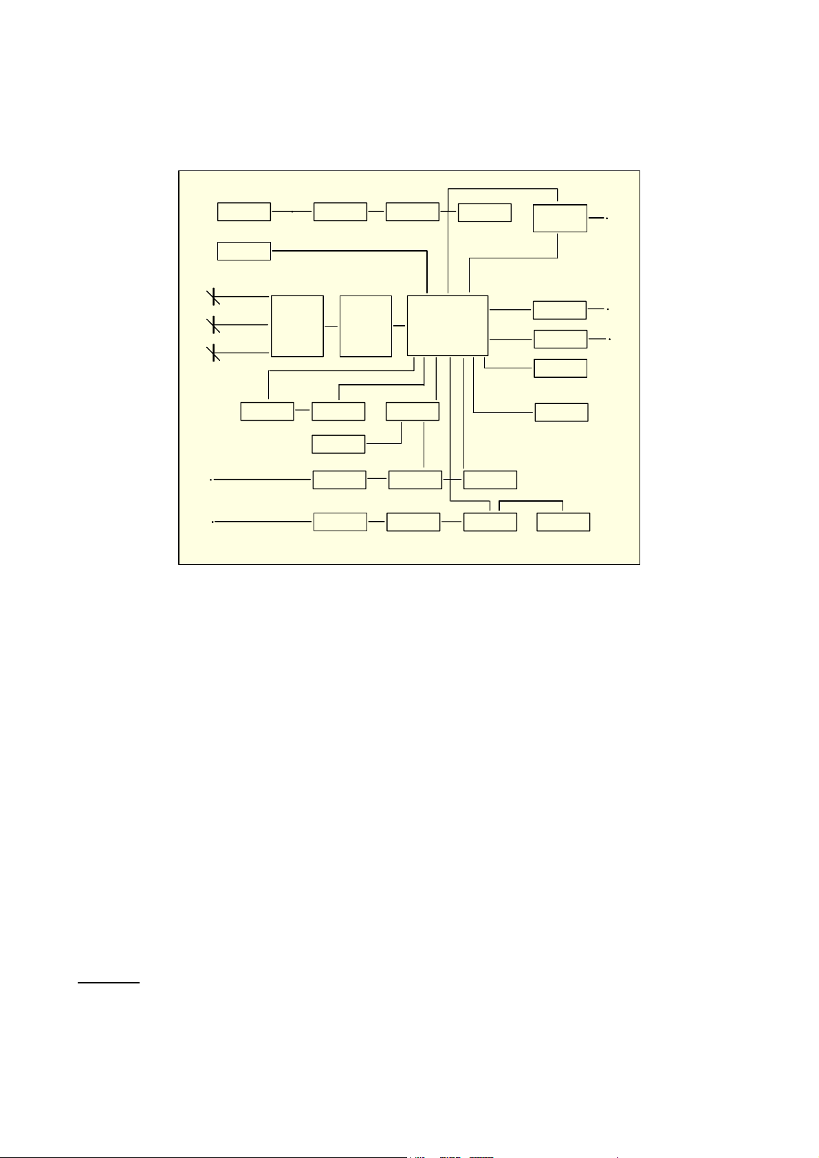
4 FUNCTIONAL DESCRIPTION
The calibrator functional block diagram is shown below.
External
Power Supply
RAM card
Internal Rj In
Internal Rj Out
Remote Rj
Contrast &
Backlight adj.
IN
OUT
Switch
and
Amplifier
Battery
A/D Converter
Display KeyboardA/D converter
Ref.
IN Switch sel.
V-mA-ž-Hz
OUT
Amplifier
• external power supply module
• microprocessor (central unit + program)
• input circuit
• reference junction compensation (Rj)
• LCD display
• operative keyboard
• analog to digital converter
• digital to analog converter
• auxiliary power supply at 24Vdc
• RAM + Clock (optional on CL524, standard on CL525)
On - Off
Microprocessor
+ Program
Input ampl.
OUT Switch sel.
V-mA-ž-Hz
Switching
Frequency IN
Comparator
D/A converter
In/Out auxiliary
PS & excitation
current for Rtd
Digital Out
Serial interface
& printer Out
RAM + Clock
Ref.
In/Out
P.S.
• PCMCIA Memory Card (on CL525 only)
4.1 Power supply
The instrument is powered by a group of four internal rechargeable Ni-Cd batteries. The battery is charged through an
external power supply module.
When required the instrument can be powered directly from the mains line without removing the batteries.
Pressing the <ON> key you will provide the dc voltage levels for the circuitry of the instrument:
IN Circuits
+ 24 V analog circuit
+ 5 V digital/analog circuit
-10 V analog circuit
..... auxiliary power supply In
13
Page 14
OUT Circuits
+ 24 V analog circuit
+ 5 V digital/analog circuit
- 5 V analog circuit
- 10 V analog circuit
..... auxiliary power supply Out
Two separate groups of voltage levels respectively for Channel 1 and Channel 2 circuits.
A galvanic insulation of 250 Vac is present between the two group of voltage levels.
4.2 Keyboard
The front panel is a thermoformed metal-click tactile polycarbonate keyboard, and has a working life of one million
operations per key.
The contact closure of the membrane keyboard is acknowledged as a coded signal by the microprocessor that
recognizes the operators' instructions .
The ergonomics are simplified with a reduced number of instruction keys referring to the display for additional set-up
instructions.
1 IN terminals
2 OUT terminals
ON Power ON switch
OFF Power OFF switch
STO Memory load
RCL Memory data recall
ÍÎ Parameter scanning during selection or decimal point position setting
0......9 Single digit setting, numerical entry, parameter scanning during selection, IN/OUT
memories
SELECT Operative menu-driven set-up
± Polarity simulation setting or parameter scanning during selection
, Decimal point simulation setting
IN/OUT Enable IN/OUT configuration set-up
MENU Scrolling between the auxiliary operative modes
ENTER Memory load - Operator's message acknowledgement
SHIFT Key secondary function
STATUS To view the pages of the actual installed operative mode and of memory stored data
HELP Operator's instruction menu pages
NUM Direct numerical setting of the simulated value
LAMP To switch the display backlight
RAMP To start the simulation program
IN and OUT displaying position swapping
ENTER + <4> or <9> Display contrast adjustment
ENTER + <±> or <,> Display backlight intensity adjustment
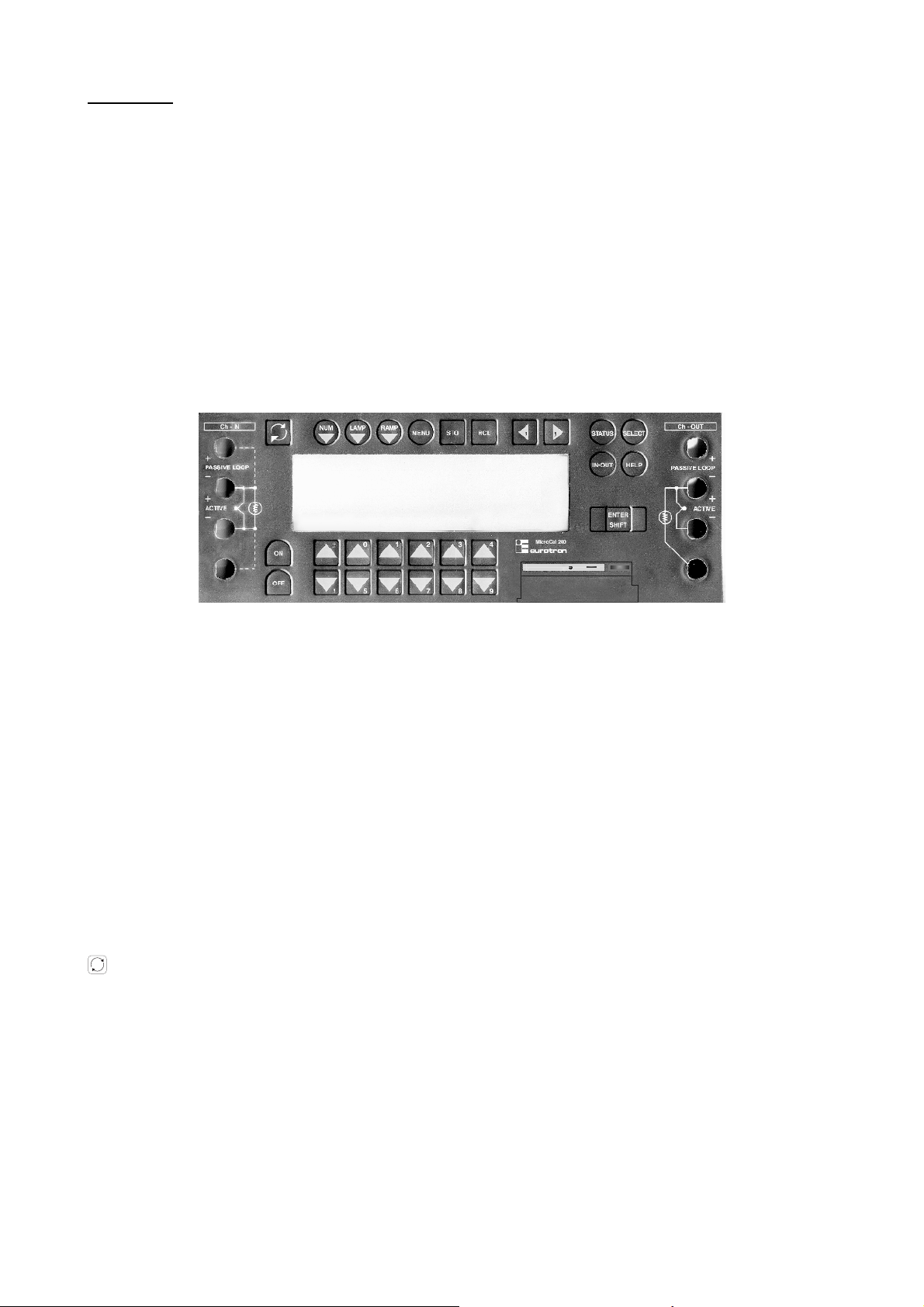
4.3 Input circuit
The A/D converter is a monolithic 20 bit ADC which uses a sigma delta conversion technique.
The analog input is continuously sampled by an analog modulator whose mean output duty cycle is proportional to the
input signal.
The modulator output is processed by an on-chip digital filter with a six-pole Gaussian response, which updates the
output data register with 20-bit binary words at word rates up to 4 kHz. The sampling rate, filter corner frequency and
output word rate are set by a master clock input supplied externally from a dedicated quartz with frequency multiple of
50/60 Hz to improve noise rejection.
14
Page 15

The inherent linearity of the ADC is excellent (0.003%), and the endpoint accuracy is ensured by a self-calibration of
zero and a full scale which is started every 5 minutes.
The self-calibration scheme can also be extended to null system offset in the input channel.
Output data are accessed through a serial port by the microprocessor in a synchronous mode.
CMOS/HCCMOS construction ensures a low power dissipation and high speed.
Analog switches provide for the gain and input parameter selection.
The front end amplifier is a high performance amplifier with very low noise and zero-drift with a combination of low-frontend noise and dc precision and it is followed by an autozero circuit.
The internal clock is set at 5 KHz for an optimum low frequency noise and offset drift.
IN
Input ampl. Microprocessor
Autozero circuitParameter select
A/D converter
Comparator (for frequency In only)
4.4 Microcontroller
The microprocontroller handles all the logic functions of the instrument, performs the linearization for non linear
transducers, compensates for the reference junction temperature, drives the digital display and acknowledges all the
operator's instructions.
The core of the circuit is the MC68332; a 32 bit integrated microcontroller, combining high performance data
manipulation capabilities with powerful peripheral subsystems and featuring a fully static, high speed complementary
metal oxide semiconductor (HCMOS) technology.
The MC68332 contains intelligent peripheral modules such as the time processor unit (TPU), which provides 16
macrocode channels to perform time related activities from a single input capture or output compared to sophisticated
pulse width modulation (PWM).
High speed serial communications are provided by the queued serial module (QSM) with available synchronous and
asynchronous protocols.
Two kilobytes of fully static standby RAM allow a fast two cycle access for system and data stacks and for variable
storage with provision for battery back-up.
Twelve chip selections enhance system integration for fast external memory or peripheral access.
These modules are connected on-chip via intermodule bus (IMB)
4.5 Firmware
The operating firmware system (256 Kbyte memory) is divided in to two sections:
• one section contains the boot-loader that is a routine to enable the base firmware loading through the serial port
• the second section contains the base firmware that handles all logic instructions for internal peripheral circuits and
performs the computation of the linearization equations. Moreover it contains the "Help" key operator's instructions
and gives instructions to the secondary graphic controller for the character generation.
The application system firmware (e.g. calibration data) is resident on a non-volatile ”Flash” EPROM.
It is used to store the installation parameters (calibration data, simulation program data, etc.)
4.6 Display
The Liquid Crystal Display module is a graphic display with high contrast and a wide viewing angle. It is equipped with a
LED backlight device to allow easy readings also in poor light conditions.
The character generation is made through the main microprocessor that gives pertinent instructions to a secondary
microprocessor driving the display in a graphic mode.
15
Page 16
Pixel driver
Main microP Aux. microP
Liquid Crystal
Segm. driver
4.7 Digital to analog converter
The D/A converter is based on a joint configuration, with a partial overlapping, of a 10-bit and 12-bit converter to obtain a
±21 bit resolution .
The two analog to digital converters are designed using the two PWM (pulse with modulation) processes available in the
micrprocessor chip.
These two PWM outputs drive the relevant switches to generate a voltage output proportional to Ton or Toff with an
accuracy theoretically absolute.
The resultant ±21 bit D/A device, driven directly by the microprocessor, converts the digital value of the selected
parameter into an analog voltage output function of the time modulation of the PWM and of the internal high stability,
high accuracy reference.
Analog switches are used to select one of the following six available output values as a function of the selected range:
-20 to +200 mV
-2 to +20 V
-200 to +2000 mV
0 to 500 Ω
0 to 5 K Ω
0 to 50 mA
The above signal, through an output buffer, is sent to an integrated circuit that will generate the voltage or current
requested by the operator's keyboard settings.
Keyboard
Microprocessor
OUT
Output amplif.
Parameter select
D/A converter
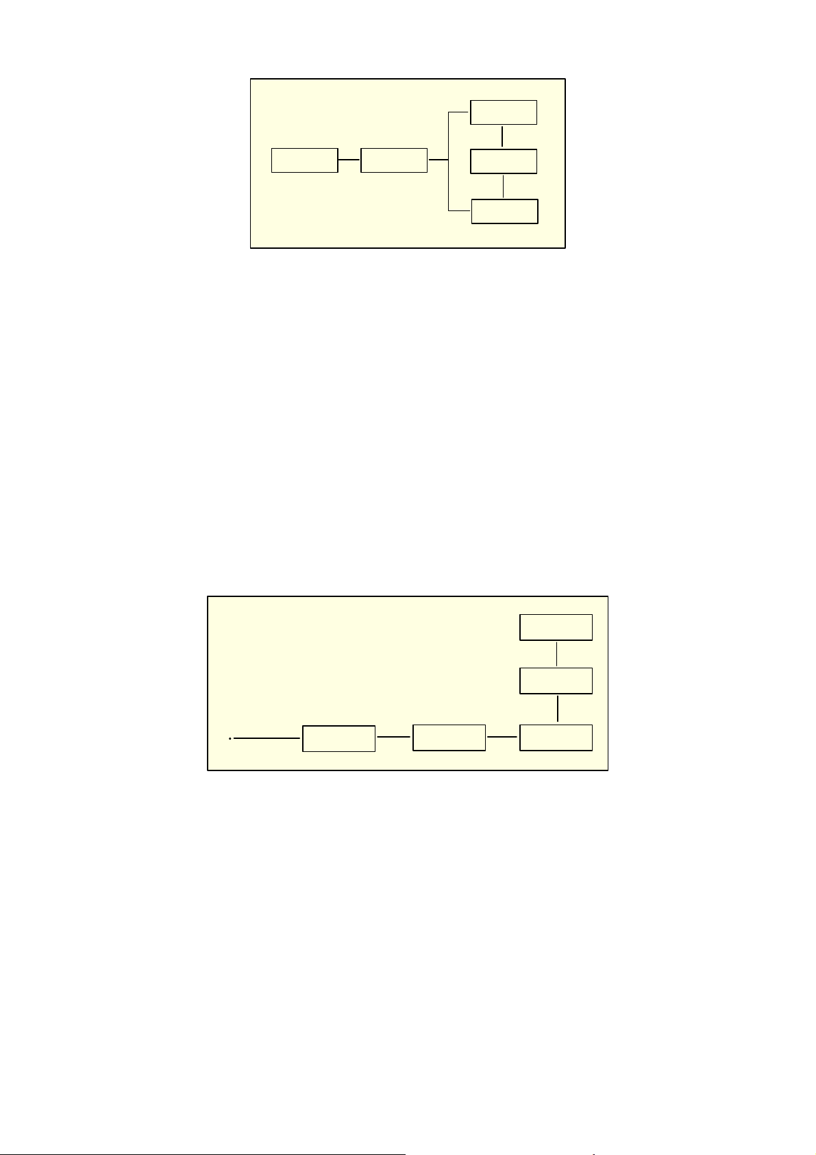
4.8 External battery charger or mains line operation
The instrument is equipped with an external power supply module for line operation 100, 115, 230 Vac 50/60 Hz.
The external power supply module uses a step down transformer, a rectifier, a filter, a serial current controller, protection
sections for over current and a battery charge circuit equipped with a timer for three different ways of charge driven by
the battery status.
The charging circuit uses two different references for:
• voltage control to 5.5 Vdc during instrument operations (5 V dc internal lines)
• battery charge current controller with a maximum of 1 Adc (when the instrument is switched Off) and a maximum of
1.8 A , limited to 5.5 V with the instrument switched On.
16
Page 17

Mains
Line ac
Transformer
dc supply to the instrument
feedback from the instrument
Rectifier-filter Timer
Current controller
4.9 Digital interface
The serial digital interface circuit is essentially based on the serial communication interface subsystem (SCI) on the chip
of the microprocessor (0 to +5V level).
An external adapter is available on request to convert TTL to RS 232 voltage levels .
4.10 Resistance and RTD measurements
The instrument can measure temperature with 2, 3 or 4 wire resistance thermometers.
For the 2 and 4 wire resistance thermometers the method used is a special configuration of a potentiometric circuit where
a constant current is injected from terminals "I+" and "I-" and the voltage drop across the thermometer is measured and
converted in engineering unit.
With 3 wire thermometers a current equivalent to that generated on terminal "I+" is injected on terminal "V-" to
compensate for connecting cable unbalance.
O---- I +
O---- V +
O---- V O---- I -
4.11 Resistance and RTD simulation
This line of calibrators is equipped with a proprietary electronic circuit for the active simulations of platinum resistance
thermometers, nickel resistance thermometers, copper resistance thermometers and resistance.
It is based on the assumption that the instrument to be calibrated will supply the excitation current to the sensor; this
current must be between 0.1 and 2 mA for up to 100 Ω nominal value RTD and between 0.01 mA and 0.5 mA for
Pt1000 and KΩ ranges.
A lower value will cause a lower accuracy level and a higher current will not allow the simulation of high resistance
values (the maximum voltage drop on the simulated resistance is 2.5 V ).
The excitation current must be applied to the pertinent terminals as indicated in par. 7.1 (simulation).
The measured current is converted to voltage through an inverting amplifier and used as a reference for the digital to
analog converter.
The output amplifier will simulate the variation of the output resistance as a function of the value set by the operator
through the keyboard.
4.12 Thermocouples input/output circuit
A thermocouple is a temperature sensor that in its most common form, consists of two wires of different composition,
joined together at one end ("measuring" junction).
The two free ends of the thermocouple must be kept at the same known temperature. These joints are , by definition, the
“reference” junction (Rj).
The reference junction is also often, but less preferably, called the “cold” junction.
17
Page 18

Tc wires
Reference Junction
emf
output
Measuring junction
Copper wires
The temperature of the reference junction can be held constant or its variation can be electrically compensated in the
associated measuring instrumentation.
A thermocouple is useful for temperature sensing because it generates a measurable electrical signal.
The signal is proportional to the difference in temperature between the measurement and the reference junctions and
it is defined, by means of tables, based on the International Temperature Scale.
The CL520 series has the reference junction located in the negative (black) terminal post. To improve overall accuracy
the terminals are designed with a very low thermal capacity.
Inside the body of the negative terminal it is placed a thin film Pt100 resistance thermometer that dynamically
measures, with high accuracy and 0.01°C resolution , the temperature of the reference junction.
The microprocessor uses the above signal (Pt100) to adjust the input signal to compensate for the Rj temperature.
Reference junction compensation can be internal, external or remote, depending upon the application requirements.
18
Page 19

5 PRE-OPERATIONAL CHECK
5.1 Unpacking
Remove the instrument from its packing case and remove any shipping ties, clamps, or packing materials.
Carefully follow any instructions given on any attached tags.
Inspect the instrument from scratches, dents, damages to case corners etc. which may have occurred during shipment.
If any mechanical damage is noted, report the damage to the shipping carrier and then notify OMEGA directly or its
nearest agent, and retain the damaged packaging for inspection.
A label, on the back of the instrument case, indicates the serial number of the instrument. The serial number is also
shown in the display.
Refer to this number for any inquiry for service, spare parts supply or application and technical support requirements.
OMEGA will keep a data base with all information regarding your instrument.
5.2 Case
The instrument case, made in shock-resistant injection molded ABS has an internal metal coating for electric interference
protection. It allows the use of the instrument in three different ways:
• portable with leather case for an easy transport
• table top with tilting feet
• panel mounted (DIN cutout)
A leather protection case is supplied as an option only on request.
5.2.1 Portable cases
Two different leather cases, with cover and shoulder strap, are available on request for the instrument alone or
instrument, printer and accessories. These are extremely useful for a practical use since they allow to leave one hand
free for instruments under test tuning.
CL520-CASE is used with the instrument alone while CL520-COMBO has a zoom for the instrument, printer and
accessories.
5.2.2 Panel mounting
For panel mounting each instrument is supplied with two mounting brackets to be installed on the two sides of the case.
The instrument bezel flange butts against the front of the mounting plate; the mounting brackets fit over the instrument
rear panel.
The bracket screws force it against the rear of the mounting panel, locking the instrument in place. Panel cutout
dimensions are 242 x 88 mm (max. panel thickness 6 mm). Rack mounting adapters (112 x 433 mm) are available with
openings for two instruments.
Front bezel 96 x 212 mm
88 mm
242 mm
5.2.3 Table top use
The case is equipped with 2 pivot feet to change the vertical viewing angle when using the instrument on the top of the
table.
19
Page 20

6 POWER SUPPLY
C
6.1 Power supply
6.1.1 Rechargeable battery
The CL520 series calibrator is powered by four built-in rechargeable batteries. The instrument is shipped with an
average level of charge.
After unpacking, a full charge of the batteries is recommended; connect the instrument to the charger module (“Off”
condition) for a period of 8 hours minimum.
Energize the display backlight device only in poor light conditions to limit battery discharge.
The Ni-Cd rechargeable batteries do not suffer when used in cyclic operations. The cyclic operation is understood as a
method of operation by which the battery is continually charged and discharged.
Avoid leaving the instrument, with batteries totally or partially discharged, for a long time without recharging.
In case of "low battery" (voltage lower than 4.6 V) the display will show the warning message indicated below and an
acoustic signal (internal buzzer) will inform the operator that he has only few additional minutes of operation and then the
battery should be recharged.
At "low battery" condition the display shows the following message.
!WARNING!
Battery low
Battery voltage is critical
onnect the line power to recharge
battery
6.1.2 Charging the battery
Battery is only partially charged at the time of purchase. Therefore charge it before using your calibrator. A total
discharge of the battery before recharging it, will allow the battery to be charged to its highest capacity.
When not in use, the battery slowly discharges. When not in use for a long period, the battery may be completely
discharged. The battery self-discharge time is minimum 2, maximum 6 months it depends, upon battery efficiency and
environment conditions. A full battery charge is obtained in 4 hours at 90% with the instrument switched "Off". Using the
instrument with line power supply the battery charge level is limited to 50% maximum.
IN
I
OUT
O
1088.4
TcT
°C
68
Rji
mVL
A "plug" symbol on the upper-left side of the display indicates that the battery charging process is active.
A -red- LED, inside the battery charger module, indicates that the charging process is active.
A -green- LED, inside the battery charger module, indicates that the power supply is connected.
0.4880
mV
6.1.3 How to maximize the life span of the battery
Disconnect the external module from ac mains supply when the battery is charged. Use the battery until it is completely
discharged. Note that the operating time decreases at low temperatures.
A Ni-Cd battery can be recharged about 500 times when used following the recommended instructions.
When replacing the Ni-Cd batteries with a new set always replace simultaneously the four pieces.
For long period of storage it is also recommended to keep the instrument at temperatures below 40°C; higher
temperatures accelerate the battery self discharging process and derate battery performances.
20
Page 21
7 ELECTRICAL CONNECTIONS
A
Appropriate extension wires should be used between the thermocouple (or instrument under calibration) and the CL520
series unless the thermocouple leads permit direct connection. Make sure that both thermocouple and compensating
cable are connected with the correct polarity. If in doubt, the polarity of the compensating leads can be checked by
connecting a length of lead to the indicator, shortening the free ends of the wires together and noting that the indicator
reading increases when the wire connection is heated. Color codes of compensating cables change in different
countries. Check the appropriate table. For RTD connection use a cable of adequate gauge to lower the overall input
resistance. The use of a cable with a good resistance balance between conductors is also necessary.
7.1 Wiring practice
Although the CL520 series calibrator is designed to be insensitive to transients or noise, the following recommendations
should be followed to reduce ac pick up in the signal leads and to ensure a good performance.
The input leads should not be run near ac line wiring, transformers and heating elements.
Input/output leads should, if possible, be twisted and shielded with the shield grounded at the end of the cable. When
shielded wires are used the shield must be connected to the negative terminal.
For a better understanding of the appropriate connection when using the instrument to simulate current into industrial 2
wire loop please, note the meaning of the terminal used.
Passive loop
This type of connection is to be used when the external loop is not equipped with the loop power supplied.
The calibrator can be, as an example, connected directly to a recorder, controller, etc. with input circuits configured for
current measurements.
Active loop
This type of connection must be used when the external loop is equipped with its loop power supplied.
The power supply is not required to be disconnected.
The loop circuit must be opened and the CL520 series connections are placed in series on the loop.
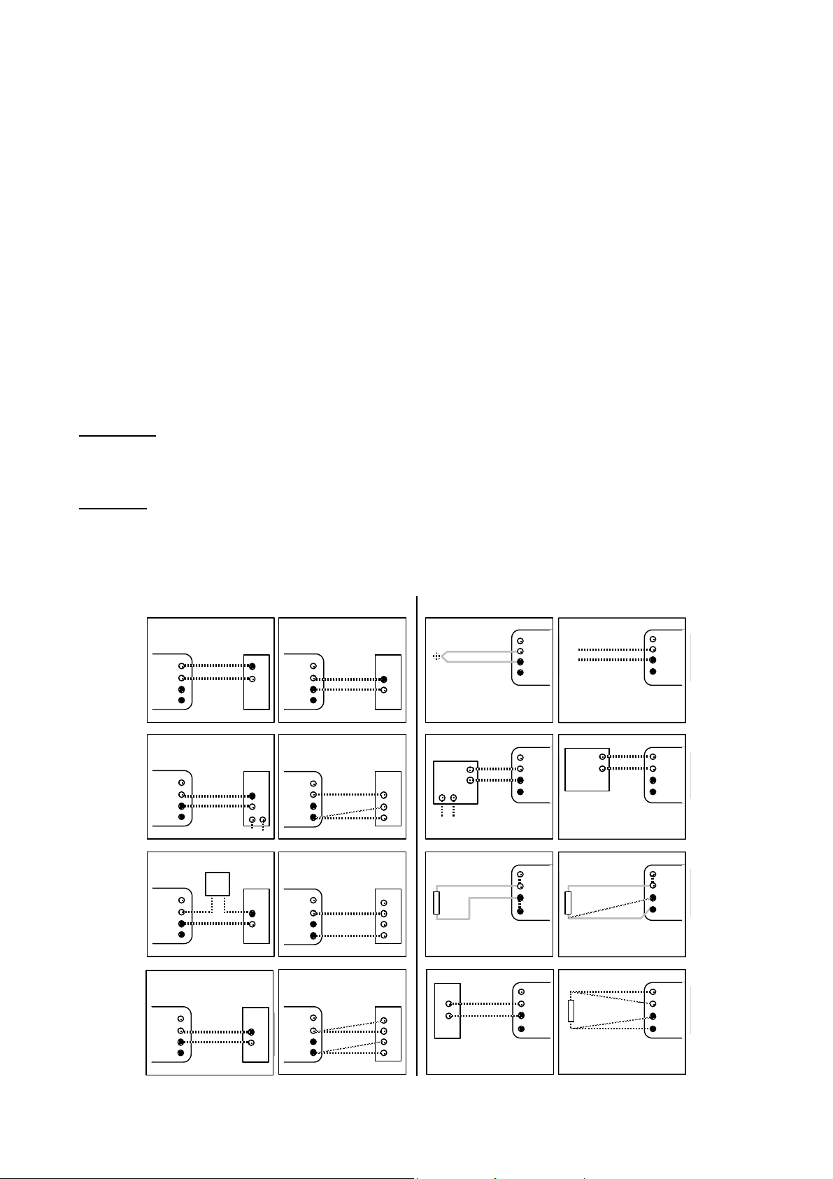
The following figure shows some examples of input/output wiring of the instrument:
SIMULATION MEASURE
Trx mA
passive
loop
+
-
Use the
compensatin g
cable for conn ections
with a Tc recorder
Recorder
for Tc
and dc
signals
CL520 series
+
--
+
-
Thermocoupl e
dc signals
CL520 series
CL520 seriesCL520 series
Trx mA
acti ve
loop
+
-
P.S.
Trx mA
acti ve
loop
P.S.
+
-
+
-
Counter
Frequency
Meter
Recorder
for Rtd
(3 wires)
Recorder
for Rtd
(2 wires)
Recorder
for Rtd
(4 wires)
B
C
A
B
C
D
A
B
C
D
Trx (4 wires)
+
--
Ext.P.S.
Rtd (2 wires)
Frequency
generator
+
OUT
--
Trx (2 wires)
+
--
Rtd (3 wires)
Rtd (4 wires)
21
Page 22

7.2 Thermocouple wires
When making measurements where additional wires have to be connected to the thermocouple leads, care must be
exercised in selecting these wire types, not only when they are claimed to be of the same composition as the
thermocouples involved, but, also, of their same "quality".
Performance results, where high precision is required and in circumstances where some types of thermocouple wire
leads are added to the original installation, should be reviewed carefully for the impact of the choice of the additional wire
leads.
The quality of the thermocouple wire is established by the limit of error to be expected with its use.
There are three recognized levels of quality:
- Special limits of error
- Standard Tc grade
- Extension wire grade
The error limits determining the grade quality differ from thermocouple type to thermocouple type, reflecting the degree of
difficulty in maintaining the precise levels of purity of the metal used.
The table below summarizes the error limits for Premium and Standard grades, while the Extension Grade wire is
characterized by limits of error exceeding those in the table.
Errors up to ±2.5 °C may be experienced when using Extension grade thermocouple wire for J and K thermocouples.
Limit of Error of thermocouple
The tolerance and the e.m.f. versus temperature reference table are defined by the IEC 584-2(Cenelec HD 446,2) and
listed as it follows:
Tolerance is meant as the maximum deviation, in °C, from the above indicated reference table with reference Junction at
0°C and the measuring junction at an appropriate temperature.
The range indicated is the temperature limit for the indicated relative errors.
Reference junction at 0 °C.
Tc Class 1 Class 2 Class 3
type T ± 0.5°C (-40 to +125°C) ± 1°C (-40 to 133°C) ± 1°C (-67 to 40°C)
± 0.004 . T (T >125°C) ± 0.0075 . T (T >133 °C) ± 0.015. T (T <-67°C)
T range -40 to +350°C -40 to +350°C -200 to 40°C
type E ± 1.5°C (-40 to 375°C) ± 2.5°C (-40 to 333 °C) ± 2.5°C (-167 to +40°C)
± 0.004.T (T >375°C) ± 0.0075.T (T >333°C) ± 0.015.T (T <-167°C)
T range -40 to 800°C -40 to 900°C -200°C to 40°C
type J ± 1.5°C (-40 to 375°C) ± 2.5°C (-40 to 333 °C)
± 0.004.T (T >375°C) ± 0.0075.T (T >333°C)
T range -40 to 750°C -40 to 750°C
type K & N ± 1.5°C (-40 to 375°C) ± 2.5°C (-40 to 333 °C) ± 2.5°C (-167 to +40°C)
± 0.004.T (T >375°C) ± 0.0075.T (T >333°C) ± 0.015.T (T <-167°C)
T range -40 to 1000°C -40 to 1200°C -200°C to 40°C
type R & S ± 1°C (0 to 1100°C) ± 1.5°C (-40 to 600 °C)
± 1 + 0.003 (T-100) ± 0.0075.T (T >600°C)
(T >1100°C)
T range 0 to 1600°C 0 to 1600°C
type B ± 4°C (600 to +800°C)
± 0.0025.T (T >600°C) ± 0.005.T (T>800°C)
T range 600 to 1700°C 800 to 1700°C
Special selected premium grade wires are available on request.
7.3 Remote connections
7.3.1 External contact
The instrument is equipped with a contact switch programmable for several functions
The type and mode of the event can be programmed (see par. 8.6) for operations:
Cnct Fnct = none / hold In / hold InP / ons IN / ons OUT /swtc In / swtc InP / swtc OUT
When the "Contact" function is selected the type of contact should be programmed as it follows:
Cnct STATE = n. open (normally open)
Cnct STATE = n. closed (normally closed)
The remote contact must be wired to the pin 11 (Contact +) and 24 (Contact -) of the back panel connector.
22
Page 23

13
11
24
NO/NC Switch
14
1
7.3.2 Remote Rj
The instrument can also operate with a remote cold junction (Rj) compensation. This operative mode require an external
Pt100 to be wired to pin 9 (Rj rem B) and 22 (Rj rem C) and pin 10 (Rj rem A) of the back panel connector as indicated in
the figure/table below.
13
10
RTD
22
9
14
1
23
Page 24

8 OPERATION & APPLICATIONS
A
r
The CL520 series calibrator has been factory calibrated before shipment.
During the start-up the operator should only select and load the required application parameters as described below.
If the instrument has been manufactured with a special thermocouple linearization, and/or with a special hardware, see
also notes in the Appendix.
The instrument should be used in environments where the temperature does not exceed the specified limits (from -10 °C
to +55 °C) and where the relative humidity is lower than 95%
N
OTE: ALL NUMERIC VALUES SHOWIN IN THE FIGURES OF THIS MANUAL ARE LISTED AS AN EXAMPLE.
During the set-up and memory loading remember that the instructions of the manual related to key operation have the
following meaning:
• <A> + <B> Press the <A> key and keeping the pressure on it, press then the <B> key.
• <A> , <B> Press in sequence first the <A> key and then the <B> key.
If an operative message (eg. “Instrument config”, ”Set”, ”Esc”, etc.) is present under the <NUM> or <LAMP> or <RAMP>
key this instruction can be entered pressing the corresponding key.
8.1 Power ON
To power on the instrument press the <ON> key; the following indication will appear for few seconds.
CL524
Version 4.001
S/N 0019220
The instrument will run an autodiagnostic routine for the self-checking of critical circuits and components.
The serial number, the version number of the firmware installed on the instrument and the next calibration date are
important peace of information for servicing activities.
To achieve a better performance in terms of accuracy wait at least for 5 minutes for the instrument to warm up.
When possible avoid using the display backlight in order to save the charge of the battery and to limit the heating inside
the instrument, so that you can obtain the most accurate results.
The instrument is ready for measurement with the previously selected operating mode with, for example, the following
indication:
AL OL
IN
O
OUT
I
0.478
AL OL
1088.4
mVL
mV
Tc K
°C
68
Rji
Annunciators area
ctive Slot indicato
Menù and option area
Lower slot display
Upper slot display
The CL520 series is able to visualize simultaneously on the display, two of the three I/O channels : pressure input (InP),
signal Input (IN) or signal output (OUT). Make reference to par. 8.8 and 8.9 for scrolling and swapping operations among
the channels.
All the keyboard operations are performed on the active slot display. To activate the desired slot display, press the <In-
Out> key in order to visualize the two arrow indicator on the slot.
Some graphical symbols could be displayed on the 'enunciators area' or in the 'option area' of the display. They have
special meanings.
These symbols are :
RAM card (PCMCIA) inserted
Low battery indication
Pump vacuum mode selected
Pressure module connected
Switch input status
24
Page 25

The external battery charger unit is connected to the mains line
8.2 Configuration Reset
It is possible to reset CL520 series to the OMEGA standard configuration pressing <RCL>+<Help> keys. The
instrument will ask to confirm the operation before to reset the instrument. All operator’s setting and data will be lose.
8.3 Next Calibration date
The instrument is equipped with a function to warn the operator when a new calibration of the instrument is
recommended .
By default the next calibration date is factory set at 01/01/80: this date set-up must be used when the warning message
is not required.
The “next calibration date” warning is enabled when the relevant date is programmed in the calibration set-up procedure.
When the instrument is powered, during the diagnostic routine, the following page is displayed with the indication of the
next programmed calibration date in the bottom line.
CL525
Version 4.001
S/N 0019220
When the programmed next calibration date has expired the instrument, at the start-up, will warn the operator with an
acoustic signal and the following message:
Next cal 30/06/97
! WARNING !
Calibration data expired
Press any key to acknowledge the warning message and to enter the operative mode. The operator should inform the
pertinent service of the organization charged for the instrument recalibration.
Press any key to acknowledge
8.4 Display adjustments
The digital display is a graphic LCD module with High contrast and a wide viewing angle. It is equipped with a LED
backlight device to allow easy reading also in poor light conditions.
Different character sizes are used to differentiate the measured and simulated value from the operative mode and from
messages to the operator as indicated below.
OUT
O
The display contrast can be adjusted using the <ENTER> + <4> or <9> keys.
The backlight intensity can be adjusted using <ENTER> + <±> or < , > keys.
Important notes :
• Remember that a high backlight intensity reduces the battery operative live
• Remember that to obtain the maximum performance in term of accuracy the backlight must be switched off. In fact
the backlight device is a source of internal heating that can contribute to the overall error of the instrument. The
stated relative accuracy is declared with the backlight device switched off.
IN
I
0.478
1088.4
mVL
mV
Tc K
°C
68
Rji
8.4.1 Display backlight
The backlight of the display can be switched “On “ and “Off “ using the <LAMP> key. If an operative message is
present under the <LAMP> key the above operation can be obtained using the <ENTER> + <LAMP> key.
25
Page 26

8.4.2 Autolamp mode
<
<
To save the energy of the battery and to extend the operative life a programmable routine is used to automatically switch
the backlight off 5 minutes after the operator's last keyboard instruction.
• To enable (or to disable) the -Autolamp- mode press the <MENU> key to obtain the <Instrument Config> message.
• Press one of the <Instrument Config> keys to obtain the following indication.
• Press the <Pag> key to visualize the next page menu
• Press the <> or <> key to reach the -Autolamp- message
• Press the <Set> key to enable the parameter change
• Press the <> or <> key to select the required “enabled” or “disabled” mode
• Press <Enter> to acknowledge the selection.
• Press the <Esc> key to return to the main operative page.
Set
Pag
Pag
Esc
Esc
Date : 28/02/93
Time : 18:12:26
Date fmt.: dmy
Cnt fnct.: none
Cnt state: n.open
Set
Probe error: 0.00°C
Avg weight S: 1
Avg weight P: 1
STO/RCL mode: single
O key funct.: swap
Autolamp off: disable
Instrument config.
ID name: 1
Baud : 9600
Printer: disable
Instrument config.
8.5 "Help" key
All the operations on the keyboard are simple and easy; any key action displays both a comprehensive instruction or
incorrect operation messages.
To make the operator's task easier during operating modes, the firmware includes a comprehensive instruction manual
with a full set of "Help" pages with an immediate indication of pertinent actions required.
Three typical pages obtained when pressing the <HELP> key are:
OUT
O
1088.4°C
IN
I
0.4880
Pg Esc Set IN Type
Lin mVL mVH V mA k Hz pulse Ω
X X1 X2 X3 X4 X5
Tc J K T F R S B U L N E
Pt100 IEC OIML USLAB US SAMA JIS
Pt 200 500 1000 1000OIML
Ω
Set Esc
E.U. : °C
Rj : internal
Rj ext : 0.00°C
ITS : 1968
Set Tc
TcT
mVL
mV
<Select> Select technical unit or
68
Rji
<NUM> Entry numeric value
<RAMP> Start programmed ramp
STATUS> View active configuration
MENU> Scroll menu functions
<STO>+<ENTER>+<n> Memory store
<RCL>+<ENTER>+<n> Memory recall
Set Select ITS Rj °C-°F-K
Pg Page selection
Esc Return to main page
<> Select tech.unit or sensor
<ENTER> Store new selection
Set Enter selection procedure
Esc Return to previous page or
keep previous setting
<> Move function pointer or
move through choices
(ENTER) Store new selection
sensor
8.6 Configuration review (Status)
The actual configuration of the instrument can be easily reviewed. Press the <STATUS> key to obtain a sequence of
pages with the relevant header. Upper or Lower slot display (basic and internal status) can be selected using the <IN-
OUT> key.
• Input channel status
26
Page 27

Actual operating mode, value, technical unit, minimum value, maximum value and median value with actual
09/10/95
Next
09/10/95
positive and negative deviation are displayed.
Input status
IN : 0.478 mV mVL
MIN: 0.4770
MAX: 0.4790
MED: 0.4780
10.000 mV +
-
The Minimum and Maximum values can be reset using the <Rst> key.
• Output channel status
Actual operating mode, value and technical unit are displayed.
CNV: Convert= electrical signal value equivalent to the technical unit value
Output status
OUT: 800.8 mbar X1
CNV: 0.000 mV
Press the <STATUS> key to enter the pages relevant to the internal status (respectively to INput channel and
OUTput channel) as it follows:
• Internal status
Information related respectively to:
− Rj internal temperature (inside black terminal);
− Rj external (memory stored value);
− Rj remote (indicates the remote temperature when the appropriate RTD is connected to the back panel
connector. If the RTD is disconnected, the indication will be "Underrange";
− Battery voltage;
− S/N: Serial number of the instrument;
− Boot program version number;
− Firmware version number
− Next calibration date (only when programmed)
− Humidity and ambient temperature (only when programmed)
Internal status OUT
BOOT vers. 1.001
PGM vers. 2.004
Next cal
Rj internal: 21.70 °C
Rj external: 0.00 °C
Rj remote : 15.00 °C
Hum : 50.0 %rH Amb T : 15.00 °C
Battery : 5.00 V
CL524
S/N 0013288
Rj internal: 21.70 °C
Rj external: 0.00 °C
Rj remote : 20.12 °C
Hum : 50.0 %rH
Battery: 5.00 V
CL524
S/N 0013288
Internal status IN
Amb T : 15.00 °C
BOOT vers. 1.001
PGM vers. 2.004
cal
• X1, X2, X3, X4, X5 Output Set Status
Five output scale factor configurations can be reviewed.
The parameters considered are:
− Type: signal or sensor
− Low: electrical signal - zero
− High: electrical signal - full scale
− Low x: display scaled zero indication
− High x: display scaled full scale indication
− Fun: linear or square
− E.U.: Symbol of the engineering unit
A typical indication will be the following:
27
Page 28

X1 Set status OUT
F
*02
130.0 °C
ITS68
*03
130.5 °C
ITS68
Type : mVL
Low : 0.000
High : 100.000
Low x: 0.000
High x: 500.000
mV
mV
Fun : linear
E.U. : rpm
Prst : none
Press any < > or < > key to select the next or the previous display of the five pages of "X" output status.
• X1, X2, X3, X4, X5 Input Set Status
From the above "X" Output Set Status pages press the <IN-OUT> key to select the INput "X" Set Status Pages.
Five input scale factor configurations can be reviewed.
The parameters considered are:
− Type: signal or sensor
− Low: electrical signal - zero
− High: electrical signal - full scale
− Low x: display scaled zero indication
− High x: display scaled full scale indication
− Fun: linear or square
− E.U.: Symbol of the engineering unit
A typical indication will be the following:
Type : mVL
Low : 0.000
High : 100.000
Low x: 0.000
High x: 500.000
X1 Set status IN
mV
mV
un : linear
E.U. : rpm
Press any < > or < > key to select the next or the previous display of the five pages of "X" input status.
• Memory status
From one of the above pages press the <STATUS> key to obtain IN and OUT memory status pages. Four pages
with a total of 20 memory stored data items are available both for INput and OUTput data items.
The following is a typical displayed page:
Memory status OUT
Tc K Rjext
Tc K Rjext
*00: 110.0 °C Tc K Rjext ITS68
*01: 120.0 °C Tc K Rjext ITS68
:
:
*04: 0.000 mV mVL
Press any < > or < > key to recall the previous o the next of the OUTput Memory Status pages (rolling 0-4, 59, 10-14, 15-19).
Press the <IN-OUT> key to recall the INput Memory Status pages.
Memory status IN
*00: 0.000 mV mVL
*01: 0.288 mV mVL
*02: 0.884 mV mVL
*03: 8.046 mV mVL
*04: 2.248 mV mVL
Press any < > or < > key to recall the previous o the following of the INput Memory Status pages (rolling 0-4,
5-9, 10-14, 15-19).
Press the <IN-OUT> key if you require to recall OUTput Memory Status pages.
• Alarm status
This page allows to review alarm warning conditions announced during operation with an acoustic signal :
An - ALARM - message will be displayed where applicable.
The - Ref. junction IN/OUT - is related to the internal automatic Rj compensation.
The - Overload IN/OUT/InP - is related to anomalous operative condition of the auxiliary power supply (e.g.
current simulation into an active loop).
The - Calibration Date - gives a warning when the next calibration date has expired.
The -Reading In/InP/Out- is related to the alarm function setting (see par. 8.10 for description and setting)
28
Page 29

Alarm status
Battery low :
Reading In :
Reading InP :
Reading Out : ALARM
Overload In :
Overload InP :
Overload Out :
Press any < > or < > key to recall the previous o the following Alarm Status pages.
Alarm status
Calibr. data : NONE
Ref. Junct. In :
Ref. Junct. Out :
CL524
Alarm status
Calibr. data : NONE
Ref. Junct. In :
Ref. Junct. Out :
CL525
Batt. Low Ramcard :
• Ram status
Two different pages are available according to the type of instrument
Ram status
Tcx/Rtdx data : NONE
Calibr. Procedure data : NONE
Logging data : NONE
Logging groups : 0
CL524
Max logging data (100 %) : 1738
Ram status
CL525
Ramcard status : off
Ramcard size : 128k
Tcx/Rtdx data : NONE
Calibr. Procedure data : NONE
Logging data : NONE
Logging groups : 0
Max logging data (100 %) : 1738
The above data are self-explanatory and summarize the operative data/mode present into the instruments
8.7 General configuration set-up
This procedure allows the set-up of the general configuration of the instrument relevant to the parameter
indicated below:
Date (sets clock date -adjusts month/day/year according to the date format enabled)
Time (sets clock time -adjusts hours/minutes/seconds)
Date fmt (selects the date format "dmy" or "mdy")
Cnct fnct (selects the external contact mode: none, hold, ons OUT, ons IN) ons=one-shot
start/stop
Cnct state (selects the external contact configuration: n.open (normally open) or n.closed
(normally closed))
ID name (sets the digital interface machine identification code from 1 to 99)
Baud (selects the baud rate among the following: Off - 300 - 600 - 1200 - 2400 - 4800 - 9600
- 19200 - 38400 - 57600 - 115200)
Printer (selects "enable" or "disable")
Aux Chn (select the external sensor connected to the auxiliary connector among the following:
none, humidity)
AmbT EU (Set the engeneering unit for ambient temperature measured with the
humidity/temperature external sensor)
Probe err (sets the temperature remote sensor deviation from the actual one for higher accurate
temperature measurements)
Avg weight S (sets the Average weight value from 1 to 255 for electrical inputs)
29
Page 30

Avg weight P (sets the Average weight value from 1 to 255 for pressure inputs)
Print
STO/RCL mode (selects store and recalls operations simultaneously for single and multiple channels)
AutoLmp (selects display backlight automatic switch-off after 5 minutes)
key function (configure the key to operate in swap (between the 2 slot display) or scroll (between
the channels) mode)
• Press the <MENU> key to obtain the following indication:
Instrument
Config.
OUT
O
IN
I
0.478
1088.4
• Press one of the <Instrument Config > keys to obtain the following indication.
Set
Pag
Date : 28/02/93
Time : 18:12:26
Date fmt.: dmy
Cnt fnct.: none
Cnt state: n.open
Esc
Instrument config.
ID name: 1
Baud : 9600
Aux Chn: none
AmbT EU: °C
• Press, if necessary, the <Pag> key to visualize the next page menù
Set
Pag
Probe error: 0.00°C
Avg weight S: 1
Avg weight P: 1
STO/RCL mode: single
O key funct.: swap
Autolamp off: disable
Esc
Instrument config.
• Press the < > or < > key to select the parameter to be modified;
• Press the <Set> key to enter the adjustment step;
• Press the < > or < > key to adjust or modify the selected parameter;
• Press the <ENTER> key to acknowledge and memory store new data;
• Press the <Esc> key to return to the previous page and in the operative mode with the new configuration.
The new configuration will be held into the memory until the next change.
mVL
mV
68
Tc K
Rji
°C
er: disable
8.8 Slot display swapping
• If the < > key is sett for the swapping mode (see par. 8.6), the operator can swap the indication displayed in the
upper slot with the lower slot one using the <
O
OUT
• Press the <
> key to obtain the following indication:
IN
I
• If the <
> key is setting for scrolling mode (see par. 8.6), the operator can swap the indication displayed in the
upper with the indication in the lower slot by pressing the <Shift> + <
> key; eg. from the display page indicated below:
IN
I
0.478
1088.4
OUT
O
1088.4
mVL
mV
°C
°C
mVL
0.4780
mV
> keys.
30
Page 31

8.9 Channels scrolling
• If the < > key is set for the scrolling mode (see par. 8.6), the operator can see on the display the non displayed
channel using the <
> key; e.g. from the display page indicated below:
O
OUT
IN
I
0.478
1088.4
mVL
mV
°C
• Press the <
> key to obtain the following indication:
OUT
O
1088.4
P
InP
°C
PL
• If the <
pressing the <Shift> + < > keys.
NOTE: I
> key is setting for the swapping mode (see par. 8.6), the operator can scroll between the channels by
F PRESSURE MODULE IS NOT CONNECTED, A ‘NO MODULE’ MESSAGE WILL BE DISPLAYED.
147.80
mbar
8.10 Decimal point position
<W > and <X> keys allow the adjustment of the decimal point position for all Tc, RTD and Hz ranges.
IN
I
0.478
OUT
O
<W > and <X> keys also allow the measuring range change for mV, Ω parameters (channel IN and OUT).
OUT
O
1088.4
IN
I
0.478
1088
mVL
mV
°C
mVL
mV
°C
8.11 Average mode
The instrument is equipped with a special algorithm to allow measurements of an unstable input signal.
The weight of the average is programmable from 1 to 255 through the general configuration set-up procedure described
in par. 8.7.
The appropriate setting should be based on a practical test taking into consideration that to an high programmed weight
corresponds a high average effect.
8.12 Autorange
This function performs the autoranging for voltage, resistance and frequency measurements.
When the function is applicable press the <Menu> key to obtain 'Autorng on' menù message.
Press <Autorng> to toggle between -On- and -Off- state to activate/disable the function.
The message "ARN" will appear on the active slot if the function is abilitate.
8.13 Alarm function
• Press the <Menu> key to obtain 'Set alm' menu message.
• Press the <Set Alm> key to obtain the following indication :
31
Page 32

Set Esc Set Alarm Out
P
Alarm setpoint : 100.00 mV
Alarm deadband : 10.00 mV
Alarm type : max
Error mode : All = Alm unchanged
Alarm set point to set the alarm value
Alarm deadband to set the deadband value
Alarm type the type of the alarm (max or min)
Error mode All = the errors don't change the alarm state
Udr off = the Underrange error switches off the alarm ; the other errors switch it on
Udr on = the Underrange error switches on the alarm ; the other errors switch it off
All off = an error switches off the alarm state
All on = an error switches on the alarm state
• Press the <> and <> keys to select the required parameter to be adjusted;
• Press the <SET> key to enable the selected parameter adjustment;
• Press the <> and <> keys to select the required application configuration;
• Press the <ENTER> key to memory store the new selection;
• Press <Enter> to return to the menu.
• Press the <Alm Enbl> or <Alm Dsbl> to enable / disable the alarm function.
NOTE : O
N THE MEASURE SLOT DISPLAY, AN 'AL' MESSAGE WILL APPEAR WHEN AN ALARM CONDITON HAPPEN.
Type= min
P
Type= max
P
Setpoint
Deadband
Alarm condition
t
Deadband
Setpoint
Alarm condition
t
8.14 Parameter or sensor selection
To select the electrical parameter or the sensor required by the application, in any measuring or simulation mode, follow
the procedure indicated below:
• Switch the instrument -ON-;
• Select the required -IN- or -OUT- mode using the <IN-OUT> key (pointer on the relevant mode)
• Press the <SELECT> key to obtain eg. the following menu page indicating all electrical ranges and thermoelectric
sensors available for the measurement channel:
• A second menu page can be obtained using the <Pg > key.
• Press <> and <> or <W > and <X> cursor keys to select the required signal or sensor;
• Press the <ENTER> key to memory load the selection; the instrument will return to the previous operative mode with
the new selected electrical signal or sensor;
Pg Esc Set IN Type
Lin mVL mVH V mA k Hz pulse Ω
X X1 X2 X3 X4 X5
Tc J K T F R S B U L N E
t100 IEC OIML USLAB US SAMA JIS
Pt 200 500 1000 1000OIML
Pg Esc Set IN Type
Lin mVL mVH V mA k Hz pulse
X X1 X2 X3 X4 X5
Tc C G D TcX
Rtd Ni100 Ni120 Cu10 CU100 RtdX
Ω
ΩΩ
32
Page 33

• By pressing the <ESC> key, instead of <ENTER>, the instrument will not acknowledge any variation and will return to
the previous parameter or sensor.
Check a correct sensor selection using the following table:
IEC α = 0.00385
OIML α = 0.003910
USLAB α = 0.003926
US α = 0.003902
SAMA α = 0.003923
JIS α = 0.003916
Pt200, Pt500, Pt1000 α = 0.00385
Pt1000 OIML α = 0.003910
8.15 Scale factor mode set-up
The “scale factor” mode is a method to read or to simulate electrical signal values in terms of engineering units eg. the
below indicated procedure shows the use of the “scale factor” function for the calibration of a potentiometric recorder
with a scale from 0.0 mbar to 400.0 mbar corresponding to an electrical linear input signal from 4 to 20 mA.
Five factors scale set-up are available both for INput and OUTput channels.
• Switch the instrument <ON>
• Select the required -IN- or -OUT- channel using the <IN-OUT> key
• Press the <SELECT> key to obtain the menu selection page
• Press the <▲> <▼> or <W > <X> cursor keys to select X1, X2, .....X5 program
• Press the <Set> key to enter the configuration page of the X1, X2, .....Xn program
Each parameter can be adjusted upon the application requirement.
• Press the <> key to select the "Type" of parameter/range
• Press the <Set> key to abilitate the parameter/range selection
• Press the <> or <> key to select the required parameter/range among:
mVL • mVH • V • mA • Hz • Ω • k Ω • 0-100 mV • 0-10 V • 1-5 V • 0-20 mA • 4-20 mA • 0-500 Ω • 0-5 kΩ
• Press the <ENTER> key to acknowledge the new setting and to memory store the new selection
• Press <> and <> keys to select the other required parameters using the same procedure indicated above
Low set the low end of the electrical signal
High set the full scale value of the electrical signal
Low X set the low end value of the engineering scaled unit
High X set the full scale value of the engineering scaled unit
Fun. select the linear or square mode
E.U. select the scaled engineering unit
Prst select the preset for the scaling function (none, 0-100mV, 0-10V, 1-5V, 0-20mA, 4-20mA, 0-
500Ω, 0-5kΩ)
• A typical numeric adjustment of a page is the following one:
Pg Esc Set IN Type
Lin mVL mVH V mA Hz K
X X1 X2 X3 X4 X5
Tc J K T F R S B U L N E
Pt100 IEC OIML USLAB US SAMA JIS
Pt 200 500 1000 1000OIML
Set Esc X1 Set
Type : mA
Low : 4.000
High : 20.000
Low X: 0.0
High X: 400.0
Ω
Ω
Fun. :linear
E.U. :mbar
Prst :none
33
Page 34

Num Esc Low X value
0.00000
• Set the required value using the in-line single-digit mode or the direct numeric entry mode pressing the <Num> key
to obtain the following indication:
Num Esc Low X value
Enter value: ( )
0.00000
• In this case the required number and decimal point position must be entered using the numeric keyboard
• Press the <ENTER> key to acknowledge and to memory store the new setting
• Press <Esc> to return to the previous page or to reject the new set-up.
• The Engineering Unit (E.U.) can be set using a continuous scrolling , with the last four keys, of all characters
indicated in the following table :
! 6 9 N Q f i
" 5 : M R e j )
# 4 ; L S d K |
$ 3 < k T c l )
% 2 = J U b m z
& 1 > I V a n y
' 0 ? H W \ o x
( / @ G X _ P w
) . A F Y ^ q v
* - B E Z ] r u
+ , C D [ s t
Library of characters
7 8 O P g h
. .
..
.....
.
.
.....
.
.
....
....
.
.
.
.
.
.
.
.
To obtain for example the following indication:
mVL
mV
mbar
IN
I
0.478
O
OUT
16.48
• After each adjustment press the <ENTER> key to memory store new data
8.16 Temperature parameters selection
This procedure is automatically enabled only when the relevant channel is programmed for thermocouple measurement
or simulation.
• Press the <SELECT> key to enter the procedure obtaining the signal or sensor menu page e.g. as it follows:
• Select the required thermocouple moving the cursor using the <>, <> or <W >, <X> keys.
• Press the <SET> key to have, for example, the following indication:
Pg Esc Set IN Type
Lin mVL mVH V mA k Hz pulse
X X1 X2 X3 X4 X5
Tc J K T F R S B U L N E
Pt100 IEC OIML USLAB US SAMA JIS
Pt 200 500 1000 1000OIML
ΩΩ
34
Page 35

Set Tc
Set Esc
E.U. : °C
Rj : internal
Rj ext : 0.00°C
ITS : 1968
E.U. (engineering unit) = °C , °F or K
Rj (reference or cold junction) = Internal
(automatic compensation at input terminals with a
calibrated thin film Pt100)
external (adjustable from -50°C to +100°C)
remote
(remote automatic compensation: requires the
connection of an external Pt100)
Rj est. = adjustable from -50 to +100 °C
ITS (Internat. Temperature. Scale) = ITS1968 or ITS1990
The internal and external Rj mode is of common use and therefore does not require any explanation.
The remote Rj (reference or cold junction ) compensation can be used either for accurate temperature readings
using an external Pt 100 or to obtain a remote automatic Rj compensation when a number of termocouples Rj are
kept at constant temperature inside a temperature controlled cabinet.
A special feature is available in the instrument to correct the error of the external Pt 100 sensor and to obtain
actual true accurate readings or Rj compensations.
When an external sensor is connected to the instrument the actual reading will be influenced by the accuracy of
the instrument itself and by the inaccuracy of the sensor used.
Through the “Instrument Config” routine the operator can select and memory load the relevant “Probe err“
specific to the resistance thermometer used.
“Probe err “ is meant as the actual deviation entity (error) of the remote Pt 100 resistance thermometer at the
required Rj temperature.
The deviation error value (in °C) can be obtained from the report of calibration of the remote RTD or through an
in-situ comparison with a working standard element.
• Press the <> and <> keys to select the required parameter to be adjusted;
• Press the <SET> key to enable the selected parameter adjustment;
• Press the <> and <> keys to select the required application configuration;
• Press the <ENTER> key to memory store the new selection;
• Press the <ESC> key twice to return to the operative mode.
8.17 Rj fast mode selection
During normal -IN- or -OUT- operation with thermocouples the operator can directly change the Rj mode as it follows:
• Press the <MENU> key and the required Rj mode:
Rj int.(ernal)
Rj ext.(ernal)
Rj rem.(ote)
using the appropriate key.
This new Rj mode will be operative until a new change occurs and it will be also stored when the instrument is switched Off-.
8.18 Resistance thermometer selection
When the measurement operative mode for resistance or resistance thermometer has been selected
• Press the<MENU> key to obtain the following indication:
3
I
wir
IN
wir
• Press the <3 wire> or the <4 wire> as required by the running application.
OUT
O
4
0.0
4.000
°C
mA
35
Page 36

The selected configuration will be memory stored until a new instruction is memory loaded.
8.19 IN-OUT data memories
The availability of a 20-step memory, both for INput and OUTput channels, represents an important feature either in
simulation or in measurement modes.
In the measurement mode it can be useful to store twenty input values pertinent to special test conditions.
In the simulation mode, the permanent availability of twenty calibration values can be useful, eg. during the calibration of
the scale of a recorder.
• To memory load each memory cell select first the appropriate operative mode and set the required value;
• Press <STO>, <0> .....<9> to memory store data in the required memory position from 0 to 9;
• Press <STO>, <ENTER>, <0> .....<9> to memory store data in the required memory position from 10 to 19;
• Press <RCL>, <0> .....<9> to recall the memory stored value from 0 to 9;
• Press <RCL>, <ENTER>, <0> .....<9> to recall the memory stored value from 10 to 19.
Memory stored data can be reviewed pressing the <STATUS> key to obtain the four pages headed - Memory Status -.
8.20 Autoscan program mode
The Autoscan program mode is based on twenty memory stored values that can be addressed, in sequence, to the
output terminals.
With the instrument in a normal operative mode, press the <MENU> key to obtain the following indication:
Set
Scan
OUT
O
• Press the <SET> key to define the Autoscan program obtaining the following indication:
Set Esc
From memory : 0
To memory : 19
Scanning time: 0:00:01
Mode : auto
• Press <> and <> keys to select the parameter to be changed;
• Press the <SET> key to enable the single parameter adjustment;
• Press <> and <> keys to adjust the value or mode required;
• Press the <ENTER> key to memory store the new data;
• Press the <ESC> key to return to the normal operative mode;
• Press the <Autoscan> key to run the program;
• Press any key to stop the program when in - Auto mode -.
Auto
IN
I
Scan
1000
0.478
mVL
mV
°C
Set autoscan
8.21 Ramp program mode
The instrument, through an easy to follow menu-driven set up, can be programmed to simulate a continuous or step
output cycle.
By programming the incremental steps to their minimum value the step ramp can be assimilated to a continuous ramp.
First select the technical unit (°C, °F or K), the type of sensor/parameter and then follow the procedure indicated below.
• Press the <MENU> key to obtain the following indication:
IN
I
0.478
1000
mVL
mV
°C
O
Set
Ramp
OUT
Auto
Ramp
36
Page 37

• Press the <Set Ramp> key
hh
T
Tend
T
• Press the <Pg > key to select Autoramp 1 or Autoramp 2;
• Press the <> or <> key to select the parameter to be modified or adjusted;
• Press the <SET> key to enable the selected parameter adjustment;
• Press the <> or <> key to modify or adjust the parameter;
• Press the <ENTER> key to memory store each parameter (if modified).
Set Pg Esc Set autoramp 1
Type : mVL
Strt : 0.000 mV
End :200.000 mV
Step : 1.000 mV
Mode : auto
Prst : none
Tstart : 0:01:00
soak : 00:00:00
soak2 : 00:00:00
Cycles : 2
:mm:ss
: 00:00:00
End
Start
Time Soak Time
T start T soak T end T soak2
step
Pyst
For fast set up of the simulation cycle (S) the operator can select one of the following programs:
− none (must be selected when Start,End ,Step are not programmed and therefore the operator has
selected and memory loaded free required values)
− 0 - 5 kΩ
− 0 - 500 Ω
− 4 - 20 mA
− 0 - 20 mA
− 1 - 5 V
− 0 - 10 V
− 0 - 100 mV
If one of the above is selected automatically each relevant datum will be shown in correspondence with Type, Start, End,
Step parameters. The step value can be eventually reprogrammed if required.
Please note the following terminology classification:
Mode
Defines the autoramp mode of operation and can be programmed as it follows:
Manual
The output value will follow the overall programmed cycle with the step by step operator's instructions. Each time
the <Autoramp > key is pressed the autoramp will move up (or down) one step value.
Auto
The instrument will generate the programmed number of cycles (eg n°2 cycles)
At the end of the last cycle the instrument will stop simulation.
Continuous
The instrument will run a non limited number of cycles until the operator’s “Stop” by using the <Autoramp> key.
8.22 Bargraph function
• Press the <Menu> key until you see the following menu:
O
Set
Bar
OUT
Set
Ref
Bar
On
1000
I
IN
0.478
37
mVL
mV
°C
Page 38

• Position the arrows by the <IN-OUT> key to select the desired channel (IN/OUT) you want to program the bargraph
Print
values.
• Press the <NUM> (SET BAR) key to obtain the following.
Set Esc
Reference : 0.000 mV
Bar resol : 10000 ppm (1.00%)
Set bargraph
• Press the <NUM> (SET) key to set the reference value for the bargraph
• Press the <▼> key to select the following line and press <NUM> (SET) to set the desired bargraph resolution of every
pixel.
• Press <ENTER> twice.
In order to set immediately a new reference value with the value actually displayed for the channel selected press the
<LAMP> (SET REF)key.
To display the bargraph press the <RAMP> (BAR-ON) key, the display will show:
Error : 14.28 %
mV
O
Set
Bar
OUT
Set
Ref
Bar
Off
8.000
(with a reference of 7.000mV)
When you modify the output value the bargraph will show the new deviation value (error) in graphical format
8.23 Switch test routine
This function is useful to test two kinds of thermostat units, one with a built-in sensor and the other with an external
sensor. When you activate this function the instrument will record the values in which the thermostat contact will change
its state (i.e. when the contact closes and when the contact reopens).
To enable this function press the <MENU> key until you reach the following menu:
• Press one of the < Instrument Config > keys to obtain the following indication.
• Move the cursor with the <▼> key to select the "Cnt fnct." line, press <NUM> (Set) and with <▲> or <▼> keys select:
"swtc OUT" or "swtc IN"; The choice depends on the thermostat type you want to test: "swtc OUT" is for thermostats
with external sensor. The OUTPUT channel of the CL520 series must be connected to the input terminal of the
thermostat and the switch of the thermostat must be connected to a 25-pin connector located on the rear panel of the
instrument.
Instrument
Config.
OUT
O
Set
Pag
Date : 28/02/93
Time : 18:12:26
Date fmt.: dmy
Cnt fnct.: none
Cnt state: n.open
Esc
IN
I
1000
Instrument config.
0.478
mVL
mV
°C
ID name: 1
Baud : 9600
er: disable
38
Page 39

Ext contact input
( rear panel)
Contact switch
Thermostat
Sensor input
"switch IN" is for a thermostat with a built-in sensor and the INPUT channel of the CL520 series must be connected to a
sensor that will read the same temperature of the thermostat and the switch of the thermostat must be connected to to a
25-pin connector located on the rear panel of the instrument.
Contact switch
Furnace
Thermostat
Built-in
sensor
Thermocople
Ext contact input
( rear panel)
• Press the <ENTER> key.
• Move the cursor with the <▼> key to select the "Cnt state" line, press <NUM> (Set) and with <▲> or <▼> keys select:
"n. open" or "n. close" depending on the normal state of the thermostat switch.
• Press the <ENTER> key twice.
• Press the <IN-OUT> key to select the channel that must be used depending on the choice previously made (switch
OUT or switch IN)
• Press the <MENU> key until you reach the following menu:
O
OUT
IN
Swt
I
On
1000
0.478
mVL
mV
°C
• Press the <RAMP> (Switch On) key to enable the switch test routine and initially the display will show:
O
Rst
Swtc
OUT
Swt
Off
1000
******** °C
******** °C
°C
When the condition of a change in the state of the thermostat switch is reached, the instrument will record the value
in which the transition occurred. Moreover, when the thermostat switch returns to the original position the instrument
will record the other value in which this new transition occurred.
O
Rst
Swtc
OUT
Swt
Off
1000
100.0 °C
98.0 °C
°C
In order to reset the recorded values for a new check press the <NUM> (Rst Swtc) key.
39
Page 40

8.24 Offset mode set-up
This mode allows the setting of the offset value in measurement and simulation to cancel the influence of an unrequired
portion of the signal.
• Select the required operative mode;
• Press the <MENU> key to obtain the following indication:
Ofs
On
O
OUT
• For the simulation mode check the indication of the instrument under calibration.
• Adjust the calibrator output to match the required indication of the instrument under test.
• Press the <Ofs On> key to enable the offset mode set-up or the <Ofs Off> to disable the offset mode;
IN
I
0.478
0.000
mVL
mV
mVL
mV
8.25 Frequency IN - OUT
The instrument is equipped with an operative mode to allow frequency measurement and simulation.
The measurement mode requires an appropriate threshold set-up from 0 to 20 V and the simulation mode an output
voltage level adjustment (0 to 20 V).
8.25.1 Frequency OUT
• Select the -Frequency Out- operative mode;
• Press the <MENU> key to obtain the following indication:
Set OUT
Hz lvl
O
OUT
• Press the <Set OUT Hz lvl> key to enable the output pulse voltage level setting, obtaining the following indication:
• Adjust the required output pulse voltage level value (range 0-20 V) with <> and <> keys or with the direct numeric
entry through the <Num> key.
• Press the <ENTER> key to acknowledge the required value.
• The output pulse frequency can be programmed using <> and <> keys or the direct numeric entry mode with the
<Num> key.
• The decimal point position can be set at 0.1 , 0.01 or 0.001 Hz using <Í > and <Î > keys.
Num Esc Set OUT Hz level
OUT: 400.0 Hz
IN
I
0.478
100.0
10.00
Hz
V
mVL
mV
8.25.2 Frequency IN
• Select the -Frequency In- operative mode;
• Press the <MENU> key to obtain the following indication:
40
Page 41

OUT
Set IN
Hz thrs
I
IN
100.0
O
0.478
Hz
mVL
mV
• Press the <Set IN Hz Thrs> to program the required threshold voltage level obtaining the following indication:
Num Esc
IN: 400.0 Hz
Set IN Hz threshold
2.50
V
• Adjust the required threshold value ( range 0-20 V) with <> and <> keys or with the direct numeric entry mode
with the <Num> key.
• Press the <ENTER> key to acknowledge the required value.
• The measurement resolution can be set at 0.1 , 0.01 or 0.001 Hz using <Í > and <Î > keys.
8.26 Transmitter simulation
The instrument can be configured as a true universal programmable signal converter with IN/OUT insulation.
This operative mode can be used e.g. as a temporary replacement of a transmitter.
• To enter this operative mode press the <MENU> key to obtain the following indication:
OUT
Set
Trx
IN
I
• Press the <Set Trx> key to enable the relevant settings as indicated below:
Set
IN - °C
Low : 0.0
High : 20000.0
Source:signal
IN err:rng=OUT L/H
Fun. :linear
• Press <> and <> keys to select the required parameter.
• Press the <Set> key to allow value adjustment (OUTrange can be selected as free or limited to be programmed).
• Press the <ENTER> key to acknowledge the required value.
O
Trx
On
4.000
0.0
Esc
Set Trx data
OUT - mA
Low : 0.0
High : 20000.0
Fail : 0.0
OUTrng: free
mA
°C
• Repeat the procedure to set other parameters.
• Press <Enter> to return to the signal converter menu.
• Press the <Trx On> key to enable the programmable signal converter operative mode.
• At the end of the application remember to switch the above operative mode off pressing the <Trx off> key.
• When the programmable signal converter operative mode is enable two additional key messages will appear on the
left-top side of the display when the <MENU> key is pressed as it follows:
OUT
O
4.000
0.0
mA
°C
I
Set
Lo Tx
IN
Set
Hi Tx
• Press the <Set LoTx> or <Set HiTx> key to memory load both Low and High limit settings relevant to the actual
measured and displayed value.
41
Page 42

8.27 Graphic operative mode
T
This operative mode is available only when the instrument is equipped with data memory and real time clock.
• To enter this operative mode press the <MENU> key to obtain the following indication:
I
Set
graph
IN
Real
graph
• Press the <Set graph> key to enable the relevant settings as it is indicated below:
Esc
Set
Souce chn : Signal
Upper limit : 20000.0
Lower limit : 0.0
Sampl. time : 0:00:00
Scaling : auto
Y axis : dynamic
• Press <> and <> keys to select the required parameter.
• Press the <Set> key to allow value adjustments (Res. time is the time interval between two readings and Y axis can
be set as dynamic or fixed)).
• Press the <ENTER> key to acknowledge new values.
• Press the <Real graph> key to obtain the direct graphic profile of the input parameter against the actual time.
20.000 mV
OUT
O
4.000
0.0
Set real graph data
Y=* 9.988 mV
X=02/08/95 12:08:36
mA
°C
0.000 mV
X= 0:18:50
The upper time counter indicates the progressive time of acquisition.
The lower time indicates the total time of the acquisition.
• Press the following keys for further instructions or to exit from the graph mode:
<
> Return to the previous page
<STATUS> Toggle numbers (enable graph only - press once more to cancel)
<RCL> Toggle grid (press once more to cancel)
<STO> Freeze graph (press once more to cancel)
<ENTER>+<Í>or<Î> Move Y axis FAST or NORMAL to review and read the actual value
for a required actual time
• The above instructions can be obtained pressing the <Help> key while in the graph mode.
8.28 Pulse IN-OUT
The instrument is equipped with an operative mode to allow pulse measurement and simulation.
The measurement mode requires an appropriate threshold set-up from 0 to 20 V and the simulation mode the set-up of
the required output voltage level (from 0 to 20 V).
8.28.1 Pulse generation
• Press the <SELECT> key to obtain the following indication:
• Select the -pulse- operative mode and press the <ENTER> key to acknowledge the selection obtaining e.g. the
following indication:
Pg Esc Set OUT Type
Lin mVL mVH V mA k Hz pulse
X X1 X2 X3 X4 X5
c J K T F R S B U L N E
Pt100 IEC OIML USLAB US SAMA JIS
Pt 200 500 1000 1000OIML
Ω
Ω
42
Page 43

IN
O
OUT
I
0.478
1000
pulse
p/t
mVL
mV
• Press the <MENU> key to obtain the following indication:
IN
I
0.478
1000
pulse
p/t
mVL
mV
Set OUT
Hz lvl
O
OUT
• Press <Set OUT Hz lvl> to enable the output pulse voltage level setting, obtaining the following indication:
Num Esc
IN: 10 p/t
Set IN Hz threshold
10.00
V
• Press the <ENTER> key to acknowledge the new setting.
• Press the <MENU> key to obtain the following indication:
IN
I
Ons
On
0.478
1000
pulse
p/t
mVL
mV
O
Set
pulse
OUT
• Press the <Set pulse> key to obtain the following indication:
Esc Set pulse
Set
Time : 0:00:30
Mode : one-shot
The "Time base" allows the setting of the pulse time base in hours, minutes and seconds. The mode can be
selected as "continuous" or "one-shot".
• Press the <ENTER> key to acknowledge the new selection. The indication on the top-left of the display "Ons On or
Off" will appear only if the one-shot operation has been selected. The instrument will return to the base indication as it
follows:
IN
O
OUT
Set
pulse
I
0.478
1000
mVL
mV
pulse
p/t
• The required pulse frequency can be set directly with <> and <> keys.
• If the "One-shot" was selected, to start the pulse train press the <Ons On> key. Remember that the technical unit
can be p/s, p/m or p/h if respectively only seconds, minutes or hours are selected on the "Time base" . If you select a
number different from a single unit (1s, 1m, 1h) the indication will be p/t (pulse/time). The limits of the "Time base
setting are 0:00:01 and 1:00:00 ( from 1 second up to 1 hour)
8.28.2 Pulse frequency measurement and counter mode
• Press the <SELECT> key to obtain the following indication:
43
Page 44

Pg Esc Set IN Type
Pt100
IEC OIML USLAB US SAMA JIS
Lin mVL mVH V mA k Hz pulse Ω
X X1 X2 X3 X4 X5
Tc J K T F R S B U L N E
Pt 200 500 1000 1000OIML
Ω
• Select the -pulse- operative mode and press the <ENTER> key to acknowledge the required operative mode
obtaining eg. the following indication:
mVL
mV
pulse
p/t
I
IN
O
OUT
0.478
1000
• Remember that the technical unit will be p/t (pulse/time) unless a single unit (1s, 1m, 1h) of the "Time base" is
selected (indication P/s, p/m, P/h)
• To set the voltage level threshold press the <MENU> key and you will obtain the following indication:
O
OUT
0.478
1000
pulse
p/t
mVL
mV
Set IN
Hz thrs
IN
I
• Press the <Set IN Hz thrs> key to enter the set-up page of the threshold voltage level:
Num Esc
IN: 0 p/t
Set IN Hz threshold
2.50
V
• Press the <ENTER> key to acknowledge the new setting and to return to the previous main page:
mVL
mV
Set IN
Hz thrs
I
IN
1000
O
OUT
0.478
p/t
• Press the <MENU> page to reach the following page that enables the pulse setting:
OUT
I
Set
pulse
IN
O
0.478
1000
pulse
p/t
mVL
mV
• Press the <Set pulse> key to obtain the following indication:
Set
Time : 0:00:30
Mode : one-shot
Esc Set pulse
The "Time base" allows the setting of the pulse time base in hours, minutes and seconds. The limits are 0:00:00 and
1:00:00. The mode can be selected as "continuous" or "one shot". "One-shot" together with a "Time base" setting of
0:00:00 allows to work in a counter mode.
• Press the <ENTER> key to acknowledge the selection. The indication on the top-left of the display "Ons On or Off"
will appear only when the one-shot operation has been selected. The instrument will return to the base indication:
pulse
p/t
mVL
mV
I
Set
pulse
IN
O
OUT
0.478
1000
44
Page 45

• In the counter mode (i.e. time base setting = 0:00:00) the <ON> key must be pressed to enable counting and to
disable counting, re-press the same key.
8.29 Percentage and error displays
The operator could require more convenient operations using percentage values for input and output instrument signals.
The above is specially required during calibration of eg. A temperature transmitter where the percentage error mode is
useful.
The use of percent displays assumes, however, that the operator sets the range limits according to the input and output
ranges of the instrument under test.
CL520 series is available with an auxiliary operative mode where the measured and simulated values can be shown in
percentage of a programmable range with numerical form and bar graph indication.
To enter the percent mode procedure follows the procedure indicated below.
• Press the <ON> key to switch the instrument -On- and to obtain the main operative page eg. as it follows:
• Move the twin arrows to the channel that require to be enabled for the percentage mode (in the above displayed page
the twin arrows are placed in the "Out" channel.
• Press several times the <MENU> key to obtain the following indication:
• Press the <Set Md%> key to obtain the following page that allows the setting of percentage scaling as it follows (the
example is relevant with the output channel).
Bar graph resolution and percentage relation with zero and full scale of the range are the information that has to be
loaded.
• Press <> and <> key to select the parameter to be programmed (or modified).
• Press the <SET> key to allow value adjustment.
• Press the <Enter> key to acknowledge the new data.
The instrument will return to the main page display. The same procedure has to be followed, moving first the twin
arrows to the "In" channel, to obtain the following page:
The "Function" field allows to display the 0 and full scale % parameters with a linear or square relation according to
the type of transmitter to be tested.
The <% Err mod> field allows to select the method for error calculation as "% of Full Scale" or "% of the Reading"
when the display of the "% Md input" is enabled and when the display of "% Error" instead of "% of range" has been
selected.
• Press the <% Md On> either on INput or OUTput channel to obtain a bar graph display that indicates the percentage
of the range actually measured or simulated.
The OUTput indication will be as it follows:
I
IN
0.478
O
OUT
Set
Md%
O
OUT
Set
0% : 0.000 mA
100% : 20.000 mA
Bar res: 10000 ppm (1.00%)
Set
0% : 0.000 mV
100% : 20.000 mV
Function : Linear
%Err. mod: F.S.
%Err. chn: Signal
Bar res : 10000 ppm (1.00%)
18.840
Md%
ON
I
IN
0.478
18.840
Esc Set %Md data
Esc Set %Md data
mVL
mV
mA
mVL
mV
mA
45
Page 46

OUT
8.840
Set%Md%Md
Off%R
26%
IN
9.040
Set%Md%Md
Off%R
52%
%
ErO
IN
Set%Md%Md
Off%ErOff
%F.S
405
12.880
ng : 2.
➧
➧
mA
The INput indication will be as it follows:
n
ng : 4.
mV
• To test the transmitter accuracy press the <% Err On> key to enable the computation and the display of the error in
the INput as a function of the simulated value referred to the OUTput value.
The "% Err" will be indicated as % of F.S. or % of Rdg according to the previous selection.
Example:
Setting a simulation output signal equivalent to 30% of the range a 30% of the input signal has to be found and
measured.
Enabling the "% Err" the error shown by the transmitter at that specific test point will be displayed eg. as it follows:
. :
ppm
mA
In the above page the error is indicated as "%of the full scale". If the error indication as "% of the reading" has been
selected the displayed page will be the following:
Set
IN
%Md
%Er
Off
%Md
Off
%Rdg : 1348 ppm
12.880
mA
When the Percentage Mode has been enabled press the <MENU> page to obtain the following indication:
Set
Lo%M
OUT
Set
Hi%M
IN
0.478
8.840
mVL
mV
mA
Press one of the above new keys to adjust automatically respectively the 0% value and the 100%value to the actually
indicated INput and OUTput signal values.
46
Page 47

9 OPTIONS & ACCESSORIES
Print
9.1 External printer
The instrument can be supplied, on request, with an external printer. The printer is a 58 mm standard paper impact type
printer to document measured or simulated values, memory stored data and to generate calibration report of instruments
under test. The printer is directly powered from CL520 series through the back panel 9 pole connector and incorporates
its own microprocessor for digital signal handling and character generation.
The printer module is supplied with cable and connector for a direct wiring to CL520 series with the following pinout:
pin 1
pin 2 5 V
pin 3 Ground
pin 4
pin 5 RX
pin 6 TX
pin 7
pin 8
pin 9
As the communication between the instrument and the printer uses a dedicated protocol no other printer can be used
than CL520-PRINT.
9.1.1 General recommendation
• The impact type printer operation requires a high power therefore the battery discharge process is accelerated
limiting the operation autonomy.
• When a battery operation print is planned provide for a full charge of the battery .
• A low level of the battery charge will cause the instrument to be automatically switched -Off- when the "Print"
instruction is given.
• When high precision measurements or simulations are required wait minimum for 30 s after each printout.
• The display backlight will automatically switch -Off- at the printer start to reduce the overall power.
• When a "Print" instruction is given press any key to stop. The printed report will show the message "...cancelled"
indicating the operator’s stop instruction.
• Press the <Adv On> key for the chart advance and then the <Adv Off> key to stop.
• If the printer is not running check the cable and connector.
• If the "Busy" signal from the printer persists for 5 s or more the following message will be displayed:
! Error !
Printer timeout
er trouble. Check printer and
• Press any key to acknowledge the warning message
9.1.2 Printer operations: General
The printer operation can be enabled through the instrument general configuration procedure (see par.8.5)
With the instrument is operative in any mode press the <MENU> key several times to obtain the following indication:
• Press one of the < Instrument Config > keys to obtain the following indication.
cables
Instrument
config.
OUT
O
IN
I
0.478
1088.4
47
mVL
mV
Tc K
°C
68
Rji
Page 48

Set
Pag
Date : 28/02/93
Time : 18:12:26
Date fmt.: dmy
Cnt fnct.: none
Cnt state: n.open
Esc
Instrument config.
ID name: 1
Baud : 9600
Printer: disable
• Press the <> or <> key to select the "Printer" parameter
• Press the <Esc> key to enter the mode selection
• Press the <>or <> key to change from "Disable" to "Enable" or viceversa.
• Select "Disable" when the printer operation is not required or the printer not available.
• Press the <ENTER> key to acknoledge and memory store the printer mode
• Press the <Esc> key to return to the normal operative mode
9.1.3 Printer operation: Normal In-Out mode
• Select the required operative mode with eg the following indication:
IN
I
0.478
O
OUT
1088.4
• Press the <MENU> key several times to obtain the following indication:
IN
I
0.478
1088.4
Prt Adv
On
O
OUT
• Press the <Adv On> key to start the chart advance, if required.
• Press the <Adv Off> key to stop the chart advance
• The <Set> key is only used for special printout requirements not installed on standard instruments.
• Press the <Prt> key to obtain a printout as for the example shown below
IN/OUT Channels
21/12/95 9:50:37
Type:TcT 68 Rji
IN : -13.60 °C
CNV: -1.572 mV
TB : -0.518 mV
MIN: -13.61 °C
MAX: 20.99 °C
MED: 3.690 °C
±
17.300 °C
Type:TcT 68 Rji
OUT: 0 °C
CNV: -1.355 mV
TB : 0.000 mV
The time and date will be printed only if the real time clock has been installed.
Error messages, if there are any, will be printed as a last line in the "Out" mode or instead of the measured value in the
"In" mode".
mVL
mV
Tc K
68
Rji
°C
mVL
mV
68
Tc K
Rji
°C
9.2 Data Logging function
This operative mode is enabled only when the battery back up option of the memory has been installed.
CL520 series indicator-simulator is equipped with an internal memory to perform a data acquisition function at
programmable time intervals. The memory has a capacity of 1500 data record.
CL525 is equipped with a removable memory card (PCMCIA) in addition to the internal RAM memory.
Logged data are structured in groups, one single group contains the data measured and stored from each -RUN Logand -End Log- operator’s instructions.
The operative mode of the Data Logging option is described in the following procedure.
48
Page 49

• Switch the instrument <ON>
0.00.01
• Select the required operative mode (e.g. for temperature measurement with thermocouple type K - IPTS 68) as
indicated at par. 8.4.2 and 8.4.3.
mVL
mV
Tc K
°C
68
Rji
I
IN
OUT
O
0.478
1032.0
Remember that the opening of input terminals will cause a fluctuation of the reading up to "Underrange" or
"Overrange" conditions.
• Press the <MENU> key several times to obtain the following indication:
O
I
Set
Log
IN
OUT
Run
Log
0.478
1032.0
mVL
mV
Tc K
°C
68
Rji
• Press the <Set Log> key to enter the page of logging parameters, obtaining the following indication:
Set Esc Set logging data
Source chn : signal
Sampl. time: 0:00:01
• Press <> and <> keys to select the required parameter to be modified (e.g. "Sampling time" = interval time
between two subsequent data acquisitions).
• Press the <Set> key to enter the page of the parameter adjustment e.g. as it follows:
Esc Set sampling time
hms
Any setting from 00 (h).00 (m).01 (s) to 12 (h).00 (m).00 (s) is accepted.
• Press the <ENTER> key to memory load the new sampling time or the <Esc> key to keep the previous setting.
The instrument will return to the indication:
Set Esc Set logging data
Source chn : signal
Sampl. time: 0:00:01
• Use the same procedure to set the additional parameters that are relevant to the graph operative mode.
• Press the <Esc> key twice to return to the normal operation page:
I
Set
Log
IN
Run
OUT
O
Log
0.478
1032.0
mVL
mV
Tc K
°C
• Press the <Run Log> key to start the data acquisition program.
The instrument will memory store the measured value at the end of each programmed time interval. The operative
mode is announced with the "Log" message on the left of the display.
mVL
mV
Tc K
°C
I
LOG
End
O
OUT
Log
0.478
1032.0
68
Rji
68
Rji
49
Page 50

• Simultaneously with each data acquisition, instead of the "LOG" symbol, the indication “***” will appear, for few
3 TcK
Rji 31/01/96 14:30:20
seconds, pointing out that the data acquisition is running. The data acquisition program ends automatically after
1500 data records or on the operator’s instruction using the <End Log> key and the display will show the following
indication:
mVL
mV
Tc K
°C
68
Rji
I
Set
Log
IN
O
Run
Log
OUT
Lst
Log
1032.0
0.478
• The operator can review each memory cell content.
• Press the <Lst Log> key to review memory stored data with e.g. the following indication:
Dis
1 TcK 68 Rji 31/01/96 14:30:20
I
2 TcK 68 Rji 31/01/96 14:30:20
I
I
4 TcK 68 Rji 31/01/96 14:30:20
I
End List
Esc
68
Logging list
Tot # : 3
The above page shows that n.3 groups of data are memory stored
• To review the content of each group press the <> or <> key to select the required group
• Press the <Dis> key to obtain all data relevant to the selected group as indicated in the following figure.
Pg Esc Logging data Pg
°C TcK 68 Rjint
* 1: 1032.0 02/18/95 16:40:20
* 2: 1034.6 02/18/95 16:40:25
* 3: 1033.4 02/10/95 16:40:30
* 4: 1034.2 02/10/95 16:40:35
Tot # : 10
The above page indicates that 10 records were memory stored and that the sampling time was set at 5 s.
• The scanning can be per page using the <Pg > or <Pg > key.
• Additional instructions can be obtained using the following keys:
Go Go to start data (press first the <Menu> key to obtain this key indication)
Go Go to end data (press first the <Menu> key to obtain this key indication)
Esc Return to the previous page
Got To select the required memory stored data
<ENTER> Return to the previous page
When the above page is displayed the operator can obtain a full or partial graph following the procedure indicated below:
• Press the <Menu> key to obtain the required mode with the following indication:
Logging data
Tot # :10
Full graph
°C TcK 68 Rjint
* 1: 1032.0 02/18/95 16:40:20
* 2: 1034.6 02/18/95 16:40:25
* 3: 1033.4 02/10/95 16:40:30
* 4: 1034.2 02/10/95 16:40:35
Logging data
Tot # :10
Part graph
°C TcK 68 Rjint
* 1: 1032.0 02/18/95 16:40:20
* 2: 1034.6 02/18/95 16:40:25
* 3: 1033.4 02/10/95 16:40:30
* 4: 1034.2 02/10/95 16:40:35
• Press the <Full graph> or <Part. graph> key to obtain e.g. the display of the graph of the memory stored values.
1370.0°C
Y=* 688.0°C
X=02/10/95 12:08:36
0.0°C
X= 0:18:50
• Press the < > key to return to the page listing the stored data and the <Esc> key to return to the normal operation
page.
50
Page 51

• If you need to start a further data logging press the <Run Log> key obtaining the following warning message:
No Logging data Yes
!Warning!
Do you want to continue and lose
all data (Tcx/Rtdx or
Calibration Procedure) ?
• Press the <Yes> key to cancel previous memory stored data and to start a new data logging or press the <No> key
to cancel the previous instruction.
9.2.1 Printout of memory stored date
The availability of the optional external printer allows the preparation of a full report of all memory stored data. See
general recommendation and printer "Enable" set-up at par. 8.7.
The procedure starts from the end of the data acquisition program with the following indication:
Set
Log
I
IN
• Press the <Lst Log> key to display the memory stored data with e.g. the following indication:
• When the printer is enabled (see instrument configuration procedure) a key <Prt> will be also displayed as it follows
• Press the <Prt> key to obtain a printout of a memory stored group
The same procedure should be used to select first required groups and then to obtain the group content printout as, for
example, it is shown below:
1:TcK 68 Rji 31/01/96 14:30:20
2:TcK 68 Rji 31/01/96 14:30:20
3:TcK 68 Rji 31/01/96 14:30:20
4:TcK 68 Rji 31/01/96 14:30:20
End List
Dis
1:TcK 68 Rji 31/01/96 14:30:20
2:TcK 68 Rji 31/01/96 14:30:20
3:TcK 68 Rji 31/01/96 14:30:20
4:TcK 68 Rji 31/01/96 14:30:20
End List
RAM contains data
Lst
Log
Run
Log
O
OUT
0.478
1032.0
Dis
Logginngs Data
Type: tck 68 Rji
Tot#: 10
Esc
Esc
Prt
Logginngs List
Tot # : 3
1:Tck 68 Rji
20/12/95 10:14
2:Tck 68 Rji
20/12/95 11:41
3:Tck 68 Rji
20/12/95 12:31
End List
1: -13.58 °C C
20/12/95 12:31:32
2: -13.58 °C C
20/12/95 12:31:33
3: -13.59 °C C
20/12/95 12:31:34
4: -13.59 °C C
20/12/95 12:31:35
5: -13.58 °C C
20/12/95 12:31:36
6: -13.59 °C C
20/12/95 12:31:37
7: -13.59 °C C
20/12/95 12:31:38
8: -13.59 °C C
20/12/95 12:31:39
9: -13.59 °C C
20/12/95 12:31:40
10: -13.59 °C HC
20/12/95 12:31:41
End Log
Logging list
Tot # : 3
Logging list
Tot # : 3
mVL
mV
Tc K
°C
68
Rji
51
Page 52

• If required press any key to stop the printer. A message "...cancelled" will appear on the report indicating a print stop
requested by the operator.
The example shows an acquisition at 1 minute intervals.
The date and time will be printed only if the real time clock is installed.
9.3 RAM card
The CL520 series is able to store logging and Calibration Procedure data into the internal RAM memory (with battery
back-up and clock if specified)
The above configuration allows to memory store up to 1500 logging data or up to 48 Calibration Procedure Tags each
with 10 calibration/verification steps.
CL525 is equipped, in addition, with a removable PCMCIA Memory Card where the data store capacity depends on the
Memory Card dimension. Memory Cards are available in sizes of 128k, 256k ,512k, and 1M bytes and the instrument
recognizes automatically the size of the Memory Card installed.
The memory stored Logging data can be extended up to 74600 (with 1M bytes memory) or up to 2120 Calibration
Procedure Taps with 10 calibration/verification steps.
When the Memory Card is inserted for the first time it is not formatted and therefore the instrument will ask if a MS-DOS
format is required.
The operator has to answer “yes” and the Memory Card operation will be enabled and the symbol “
main operative page.
To proceed with the above step the writing protection (see the relevant lever in the Memory Card) must be excluded.
When the Memory Card is inserted and operative Logging data will be memory stored in it as well as the Calibration
Procedure downloaded from a PC (using the Calibration Softwere package).
When the “Memory Card” is removed the data stored in the internal RAM (with battery backup) will become “visible”.
Special linearizations (Tcx and RTDx) will be always resident in the internal RAM.
The “Status” page identified with “Ram Status” header will show important information relevant to Memory Card and to
the internal RAM (such as Logging data stored,Calibration Procedure and special linearization loaded, Logging data
available capacity, group of Logging Data stored and, when installed, the size of the Memory Card.
IMPORTANT NOTE
FOR DATA SAFETY THE MEMORY CARD SHOULD BE INSERTED ONLY WHEN THE INSTRUMENT SHOWS THE MAIN OPERATIVE PAGE AND
THE LOGGING MODE HASN’T BEEN STARTED YET.
“ shown on the
52
Page 53

10 DIGITAL INTERFACE
CL520 series is equipped with a digital interface at TTL level to allow communication with a Personal Computer.
A normal or galvanic insulated TTL to RS232 adaptor is available on request.
To set the communication parameters see the procedure in the par. 8.5.
10.1 Digital output wiring practice
The wiring to digital output signals is made through a mini DIN connector mounted on the lower end of the case.
The pertinent connections are indicated below :
Rx
Tx
SHIELD
Female miniDIN connector
(case mounted - external view)
ground
5 V
For easy interconnections a miniDIN connector with cable can be supplied on request.
The conductors color codes can change with different supplier; please check before using.
4 5 6
8
7
Front view
3
1 2
LINDY
CINCH
pin 1 : brown black
pin 2 : red green
pin 3 : green blue
pin 4 : gray gray
pin 5 : purple yellow
pin 6 : blue white
pin 7 : orange red
pin 8 : yellow brown
The basic circuit and connections are as follows:
10 µF, 16 V
10 µF, 16 V
10 µF, 16 V
Tx
Rx
+
+
+
10 µF, 16 V
6 2 16 10
11
12
ICL 232
1
TSC 232
3
4
5
15 8
+ 5 V
+
10 µF, 16 V
14
Rx
IBM
13
Tx
IBM
Ground
IBM
Tx
+ 5 V
Mini-Din
TTL to RS 232 converter
IBM - PC
D
Rx
B
2
5
3
2
7
53
Page 54

10.2 Communication protocol
The exchange of information when a CL520 series is connected with a PC is as it follows:
10.2.1 Computer data request from CL520 series
Computer CL520 series
Tx IDNAME Î Rx IDNAME Proceed if name acknowledged
Rx IDNAME Í Tx IDNAME If not, do not answer
Tx Instruction Î Rx Instruction
Rx Instruction Í Tx Instruction
Tx char Î Rx char
Rx DATA 1 Í Tx DATA 1
Tx char Î Rx char
Rx DATA 2 Í Tx DATA 2
Tx char Î Rx char
Rx DATA 3 Í Tx DATA 3
Tx char Î Rx char
Rx DATA 4 Í Tx DATA 4
Tx CHKSUM Î Rx CHKSUM
Rx CHKSUM Í Tx CHKSUM
IDNAME, Instruction, DATA 1, DATA 2, DATA 3, DATA 4 and CHKSUM are 8-bit decimal values.
Tx CHKSUM = DATA1 + DATA2 + DATA3 + DATA4 .AND. 7F
Rx CHKSUM (checksum) = DATA1 + DATA2 + DATA3 + DATA4 .AND. FF
The above is useful to verify correct received data.
The minimum time-out of CL520 series is 3 seconds.
Reading values
00 - Actual I/O type---------------------------------------------------------------------- RX
0 I/O TYPE
1 I/O SUBTYPE
2 I/O FLAGS_IO (H)
3 I/O FLAGS_IO (L)
01 - Electrical Input value (invalue-final)----------------------------------------- RX
0 VALUE (HH) or 0x7f (denotes error)
1 VALUE (H) 2 VALUE (L) 3 VALUE (LL) or Error code
02 - Actual engineering unit---------------------------------------------------------- RX
0 'X' (ASCII CODE)
1 'X' (ASCII CODE)
2 'X' (ASCII CODE)
3 'X' (ASCII CODE)
05 - Output value (outvalue-final) -------------------------------------------------- RX
0 VALUE (HH)
1 VALUE (H)
2 VALUE (L)
3 VALUE (LL)
06 - Pure Electrical Input value (invalue-pure/FATT) ------------------------ RX (Cnv)
0 VALUE (HH) or 0x7f (denotes error)
1 VALUE (H) 2 VALUE (L) 3 VALUE (LL) or Error code
07 - Pure Output value (outvalue-pure/FATT)---------------------------------- RX (Cnv)
0 VALUE (HH)
1 VALUE (H)
2 VALUE (L)
3 VALUE (LL)
08 - Actual pure I/O type -------------------------------------------------------------- RX (Cnv)
0 I/O TYPE
1 I/O FACTOR
2 I/O FLAGS - IO (H)
3 I/O FLAGS - TO (L)
54
Page 55

09 - Actual pure engineering unit -------------------------------------------------- RX (Cnv)
0 'X' (ASCII CODE)
1 'X' (ASCII CODE)
2 'X' (ASCII CODE)
3 'X' (ASCII CODE)
0A - Max Electrical input value (invalue_max)--------------------------------- RX
0 VALUE (HH) or 0x7f (denotes error)
1 VALUE (H) 2 VALUE (L) 3 VALUE (LL) or Error code
0B - Min Electrical input value (invalue_min) ---------------------------------- RX
0 VALUE (HH) or 0x7f (denotes error)
1 VALUE (H) 2 VALUE (L) 3 VALUE (LL) or Error code
0C - Mean Electrical input value (invalue_med) ------------------------------- RX
0 VALUE (HH) or 0x7f (denotes error)
1 VALUE (H) 2 VALUE (L) 3 VALUE (LL) or Error code
0D - Deviation Electrical input value (invalue_scost) ----------------------- RX
0 VALUE (HH) or 0x7f (denotes error)
1 VALUE (H) 2 VALUE (L) 3 VALUE (LL) or Error code
0E - Battery voltage--------------------------------------------------------------------- RX
0
1
2 VBATT (H)
3 VBATT (L)
10 - Flags 2 -------------------------------------------------------------------------------- RX
0
1
2 errout_global
3 -
15 - Date ------------------------------------------------------------------------------------ RX
0 DAY
1 MONTH
2 YEAR
3 -
16 - Time------------------------------------------------------------------------------------ RX
0 HOURS
1 MINUTES
2 SECONDS
3 -
1A - Actual offset value (value_offset) ------------------------------------------- RX
0 VALUE (HH)
1 VALUE (H)
2 VALUE (L)
3 VALUE (LL)
1C - Firmware version ----------------------------------------------------------------- RX
0 'X' (ASCII CODE)
1 'X' (ASCII CODE)
2 'X' (ASCII CODE)
3 'X' (ASCII CODE)
1E - Actual internal Rj (rj_int - 2 decimals)-------------------------------------- RX
0 VALUE (HH) or 0x7f (denotes error)
1 VALUE (H) 2 VALUE (L) 3 VALUE (LL) or Error code
1F - Actual external Rj (rj_ext - 2 decimals)------------------------------------- RX
0 VALUE (HH)
1 VALUE (H)
2 VALUE (L)
3 VALUE (LL)
55
Page 56

20 - Remote Rj (rj_rem - 2 decimals) ---------------------------------------------- RX
0 VALUE (HH) or 0x7f (denotes error)
1 VALUE (H) 2 VALUE (L) 3 VALUE (LL) or Error code
21 - Pure linearization Input value (invalue_puretab/FATT)--------------- RX
0 VALUE (HH) or 0x7f (denotes error)
1 VALUE (H) 2 VALUE (L) 3 VALUE (LL) or Error code
22 - Pure linearization Output value (outvalue_puretab/FATT)----------- RX
0 VALUE (HH)
1 VALUE (H)
2 VALUE (L)
3 VALUE (LL)
2F - Actual selection ------------------------------------------------------------------- RX
0 Actual I/O channel (0 = OUTPUT - 1 = INPUT - 2=PRESSURE)
1 Actual slot display (0=Lower - 1=Upper)
2 I/O Channel for lower slot
3 I/O Channel for upper slot
30 - Serial number ---------------------------------------------------------------------- RX
0 VALUE (H)
1 VALUE (L)
2 3 -
31 - Actual decimals number -------------------------------------------------------- RX
0 Displayed decimals
1 Pure signal decimals
2 3 -
32 - Calibrator ID (CL524 = 9 - CL525 = 11)-------------------------------------- RX
0 Instrument ID
1 Instrument ID
2 Instrument ID
3 Instrument ID
33 - Pulse timebase OUT ------------------------------------------------------------- RX
0 HOURS
1 MINUTES
2 SECONDS
3 -
34 - Pulse mode OUT ------------------------------------------------------------------ RX
0 flag_pulse (H)
1 flag_pulse (L)
2 3 'X' (ASCII CODE)
35 - Pulse timebase IN ---------------------------------------------------------------- RX
0 HOURS
1 MINUTES
2 SECONDS
3 -
36 - Pulse mode IN ---------------------------------------------------------------------- RX
0 flag_pulse
1 flag_pulse (L)
2 3 -
3C - Firmware version ----------------------------------------------------------------- RX
0 'X' (ASCII CODE)
1 'X' (ASCII CODE)
2 'X' (ASCII CODE)
3 'X' (ASCII CODE)
3D - Boot loader firmware version------------------------------------------------- RX
0 'X' (ASCII CODE)
1 'X' (ASCII CODE)
2 'X' (ASCII CODE)
3 'X' (ASCII CODE)
40 - Flags X1 scaling OUT ----------------------------------------------------------- RX
56
Page 57

0 flag_x (H)
1 flag_x (L)
2 SUBTYPE
3 -
41 - Flags X2 scaling OUT ----------------------------------------------------------- RX
0 flag_x (H)
1 flag_x (L)
2 SUBTYPE
3 -
42 - Flags X3 scaling OUT ----------------------------------------------------------- RX
0 flag_x (H)
1 flag_x (L)
2 SUBTYPE
3 -
43 - Flags X4 scaling OUT ----------------------------------------------------------- RX
0 flag_x (H)
1 flag_x (L)
2 SUBTYPE
3 -
44 - Flags X5 scaling OUT ----------------------------------------------------------- RX
0 flag_x (H)
1 flag_x (L)
2 SUBTYPE
3 -
45 - Engineering unit X1 scaling OUT -------------------------------------------- RX
0 'X' (ASCII CODE)
1 'X' (ASCII CODE)
2 'X' (ASCII CODE)
3 'X' (ASCII CODE)
46 - Engineering unit X2 scaling OUT -------------------------------------------- RX
0 'X' (ASCII CODE)
1 'X' (ASCII CODE)
2 'X' (ASCII CODE)
3 'X' (ASCII CODE)
47 - Engineering unit X3 scaling OUT -------------------------------------------- RX
0 'X' (ASCII CODE)
1 'X' (ASCII CODE)
2 'X' (ASCII CODE)
3 'X' (ASCII CODE)
48 - Engineering unit X4 scaling OUT -------------------------------------------- RX
0 'X' (ASCII CODE)
1 'X' (ASCII CODE)
2 'X' (ASCII CODE)
3 'X' (ASCII CODE)
49 - Engineering unit X5 scaling OUT -------------------------------------------- RX
0 'X' (ASCII CODE)
1 'X' (ASCII CODE)
2 'X' (ASCII CODE)
3 'X' (ASCII CODE)
4B – Auxiliary channel config ------------------------------------------------------ RX
0 Ch setting (0=none 1=Humidity)
1 Ambient Temp. Tecnical Unit (0= °C 1= °F 2= K)
2 3 -
4C – Humidity measurements ------------------------------------------------------- RX
0 VALUE (HH)
1 VALUE (H)
2 VALUE (L)
3 VALUE (LL)
4D – Ambient temperature measurements-------------------------------------- RX
0 VALUE (HH)
1 VALUE (H)
2 VALUE (L)
3 VALUE (LL)
50 - Flags X1 scaling IN --------------------------------------------------------------- RX
0 flags_x (H)
57
Page 58

1 flags_x (L)
2 SUBTYPE
3 -
51 - Flags X2 scaling IN --------------------------------------------------------------- RX
0 flags_x (H)
1 flags_x (L)
2 SUBTYPE
3 -
52 - Flags X3 scaling IN --------------------------------------------------------------- RX
0 flags_x (H)
1 flags_x (L)
2 SUBTYPE
3 -
53 - Flags X4 scaling IN --------------------------------------------------------------- RX
0 flags_x (H)
1 flags_x (L)
2 SUBTYPE
3 -
54 - Flags X5 scaling IN --------------------------------------------------------------- RX
0 flags_x (H)
1 flags_x (L)
2 SUBTYPE
3 -
55 - Engineering unit X1 scaling IN ----------------------------------------------- RX
0 'X' (ASCII CODE)
1 'X' (ASCII CODE)
2 'X' (ASCII CODE)
3 'X' (ASCII CODE)
56 - Engineering unit X2 scaling IN ----------------------------------------------- RX
0 'X' (ASCII CODE)
1 'X' (ASCII CODE)
2 'X' (ASCII CODE)
3 'X' (ASCII CODE)
57 - Engineering unit X3 scaling IN ----------------------------------------------- RX
0 'X' (ASCII CODE)
1 'X' (ASCII CODE)
2 'X' (ASCII CODE)
3 'X' (ASCII CODE)
58 - Engineering unit X4 scaling IN ----------------------------------------------- RX
0 'X' (ASCII CODE)
1 'X' (ASCII CODE)
2 'X' (ASCII CODE)
3 'X' (ASCII CODE)
59 - Engineering unit X5 scaling IN ----------------------------------------------- RX
0 'X' (ASCII CODE)
1 'X' (ASCII CODE)
2 'X' (ASCII CODE)
3 'X' (ASCII CODE)
5A - Number of logging groups----------------------------------------------------- RX
0 VALUE (HH)
1 VALUE (H)
2 VALUE (L)
3 VALUE (LL)
5B - Internal Rj OUT (rj_int - 2 decimals) ---------------------------------------- RX
0 VALUE (HH) or 0x7f (denotes error)
1 VALUE (H) 2 VALUE (L) 3 VALUE (LL) or Error code
5C - Internal Rj IN (rj_int - 2 decimals)-------------------------------------------- RX
0 VALUE (HH) or 0x7f (denotes error)
1 VALUE (H) 2 VALUE (L) 3 VALUE (LL) or Error code
61 - First recorded value of switch test routine ------------------------------------- RX
0 VALUE (HH) or 0x7f (denotes error)
1 VALUE (H) -
58
Page 59

2 VALUE (L) 3 VALUE (LL) or Error code
62 - Second recorded value of switch test routine--------------------------------- RX
0 VALUE (HH) or 0x7f (denotes error)
1 VALUE (H) 2 VALUE (L) 3 VALUE (LL) or Error code
The Computer must combine HH - H - L - LL 8-bit wide each in a 32 bit long word value as it follows:
V32 = HH *2
IF V32 >= 2
24
+ H * 216 + L * 28 + LL
31
then V32 = V32 - 2
32
or the H and L 8-bit wide each in a 16-bit word value as it follows:
V16 = H * 28 + L
IF V16 >= 2
15
then V16 = V16 - 2
16
I/O TYPE or CNV TYPE 0 = mVL
1 = mVH
2 = V
3 = mA
4 = Ω
5 = KΩ
6 = Hz
7 = pulse
8 = Tc
9 = RTD
10 = X scaling
I/O SUBTYPE (for I/O TYPE = 8) (for I/O TYPE = 9) (for I/O TYPE = 10)
0 = Tc J 15 = Pt 100 IEC/DIN 0 = X1 scaling
1 = Tc K 16 = Pt OIML 1 = X2 scaling
2 = Tc T 17 = Pt USLAB 2 = X3 scaling
3 = Tc F 13 = Pt US 3 = X4 scaling
4 = Tc R 19 = Pt SAMA 4 = X5 scaling
5 = Tc S 20 = Pt JIS
6 = Tc B 21 = Pt 200
7 = Tc U 22 = Pt 500
8 = Tc L 23 = Pt 1000
9 = Tc N 24 = Pt 1000 OIML
10 = Tc E 25 = Ni 100
11 = Tc C 26 = Ni 120
12 = Tc G 27 = Cu 10
13 = Tc D 23 = Cu 100
14 = Tc X 29 = RTD X
I/O FLAGS_IO
(FLAGS_IO) .AND. 3 0 = Rj internal
1 = Rj external
2 = Rj remote
(FLAGS_IO) .AND. 4 0 = ITS 68
1 = ITS 90
(FLAGS_IO) .AND. &18 0 = °C
1 = °F
2 = K
(FLAGS_IO) .AND. &20 0 = 4 w (for Ω and k Ω IN)
1 = 3 w (for Ω and k Ω IN)
(FLAGS_IO) .AND. &C0 0 = 0 dec Tc/RTD
1 = 1 dec Tc/RTD
2 = 2 dec Tc/RTD
(FLAGS_IO).AND. &300 1 = 1 dec Hz
2 = 2 dec Hz
3 = 3 dec Hz
IF Measure (HH) or 0 = None
Inp CNV (HH) or 1 = Overrange
59
Page 60

Max (HH) or 2 = Underrange
Min (HH) or 3 = Rj err. (high)
Med (HH) or 4 = Rj err. (low)
Dev (HH) or 5 = Calc. err.
Bar (HH) or 6 = ******
Rj int (HH) o 7 = Overflow
Rj rem (HH) = 7 F (HEX) then the 8 = Underflow
corresponding value LL represent the error 9 = Measure waiting
code: 10 = Overvoltage
(Also for errout_global) 11 = Overcurrent
14 = Zero err.
15 = Frq. err.
"X" represents the ASCII code of the CL520 series PC
corresponding character, for the following
characters, you must apply the conversion 128<--------------------->248
table, as shown: 129<--------------------->234
130<--------------------->230
131<--------------------->24
132<--------------------->25
133<--------------------->224
(FLAGS_PULSE).AND. 1 0 = Continuous
1 = One - shot
(FLAGS_X).AND. 7 (0 - 5) = x scaling decimals
(FLAGS_X).AND. 8 0 = Linear
1 = Square
(FLAGS_X).AND. & 30 (1 - 3) = Pure signal decimals (for Hz)
V bat must be divided by 100 and represents the battery voltage with 2 decimals.
YEAR represents the year between 00-99.
Rj int, ext and rem represent the reference junction values in °C and must be divided by 100.
10.2.2 Computer data setting from PC
Computer CL520 series
Tx IDNAME Î Rx IDNAME Proceed if name acknowledged
Rx IDNAME Í Tx IDNAME If not, do not answer
Tx Instruction Î Rx Instruction
Rx Instruction Í Tx Instruction
Tx DATA 1 Î Rx DATA 1
Rx char Í Tx char
Tx DATA 2 Î Rx DATA 2
Rx char Í Tx char
Tx DATA 3 Î Rx DATA 3
Rx char Í Tx char
Tx DATA 4 Î Rx DATA 4
Rx char Í Tx char
Tx CHKSUM Î Rx CHKSUM
Rx CHKSUM Í Tx CHKSUM
IDNAME, Instruction, DATA 1, DATA 2, DATA 3, DATA 4 and CHKSUM are 8-bit decimal values
CHKSUM (checksum) = DATA1 + DATA2 + DATA3 + DATA4 .AND. 7F
The CL520 series receives and verifies the checksum, when not valid, it doesn't accept the data transmitted. The
minimum time-out of the CL520 series is 3 seconds.
Writing values
80 - Actual I/O type---------------------------------------------------------------------- TX
0 I/O TYPE
1 I/O SUBTYPE
2 I/O FLAGS_IO (H)
3 I/O FLAGS_IO (L)
60
Page 61

81 - Output value (outvalue_final)-------------------------------------------------- TX
0 VALUE (HH)
1 VALUE (H)
2 VALUE (L)
3 VALUE (LL)
82 - Actual selection-------------------------------------------------------------------- TX
0 Actual I/O slot display (0=Lower - 1=Upper)
1 2 3 -
83 - Date ------------------------------------------------------------------------------------ TX
0 DAY
1 MONTH
2 YEAR
3 -
84 - Time------------------------------------------------------------------------------------ TX
0 HOURS
1 MINUTES
2 SECONDS
3 -
85 - Reset Max,Min and Input filter ------------------------------------------------ TX
0 1 2 3 -
87 - States control----------------------------------------------------------------------- TX
0 Offset state (0=OFF - 1=ON - 2=ON on degrees for Tc /RTD - 255 = Don't modify)
1 Avg. state (0=OFF - 1=ON - 255 = Don't modify)
2 Hold state (0=OFF - 1=ON - 255 = Don't modify)
3 Set LOIN-HIIN (1=SET LoIN - 1=Set HiIN - 255 = Don't modify)
88 - Filter weight ------------------------------------------------------------------------- TX
0 Filter weight (1-255)
1 2 3 -
89 - Function control ------------------------------------------------------------------- TX
0 Output function (0=OFF Autoramp,Autoscan,Trx - 1=Start Autoscan - 2=Start Autoramp - 3=Start Trx 255 = Don't modify)
1 Input function (0=OFF Logging - 1=Start Logging - 255 = Don't modify)
2 I/O function (0 = OFF One-shot - 1 = ON One-shot - 255 = Don't modify)
3 -
8A - Store memory ---------------------------------------------------------------------- TX
0 Channel (0=OUT - 1=IN - 2=INP)
1 Memory number (0-19)
2 3 -
8B - Recall memory --------------------------------------------------------------------- TX
0 Channel (0=OUT - 1=IN - 2=INP)
1 Memory number (0-19)
2 3 -
8E - Actual states control 2 ---------------------------------------------------------- TX
0 Autorange state (0=Off - 1=On - 255=no modify)
1 2 3 -
8F - Reset display error numbers -------------------------------------------------- TX
0 1 2 3 -
99 - Reset Output value --------------------------------------------------------------- TX
0 1 2 3 -
9A - Actual external Rj (rj_ext - 2 decimals) ------------------------------------ TX
61
Page 62

0 VALUE (HH)
1 VALUE (H)
2 VALUE (L)
3 VALUE (LL)
9B - Pulse timebase OUT ------------------------------------------------------------- TX
0 HOURS
1 MINUTES
2 SECONDS
3 -
9C - Pulse mode OUT ------------------------------------------------------------------ TX
0 flag_pulse (H)
1 flag_pulse (L)
2 3 -
9D - Pulse timebase IN----------------------------------------------------------------- TX
0 HOURS
1 MINUTES
2 SECONDS
3 -
9E - Pulse mode OUT ------------------------------------------------------------------ TX
0 flag_pulse (H)
1 flag_pulse (L)
2 3 -
9F - Reset recorded values of switch test routine---------------------------- TX
0 1 2 3 -
C5 - Scroll / Swap selecting---------------------------------------------------------- TX
0 Mode (0=Swap - 1=Scroll)
1 2 3 -
F2 - Reset instrument ----------------------------------------------------------------- TX
0 1 2 3 -
F3 - Power off instrument ------------------------------------------------------------ TX
0 1 2 3 -
F4 - Set baut rate by instrument table -------------------------------------------- TX
0 VALUE(0=OFF,1=300,2=600,3=1200,4=2400,5=4800.6=9600,7=19200,8=38400,9=57600,10=115200)
1 2 3 -
F5 - Set baut rate directly ------------------------------------------------------------- TX
0 VALUE (HH)
1 VALUE (H)
2 VALUE (L)
3 VALUE (LL)
The computer must split a 32 bit long word into 4 bytes of 8 bit as it follows:
Bits 31-24 --> HH
Bits 23-16 --> H
Bits 15-8 --> L
Bits 7-0 --> LL
IN/OUT selection 0 = Select 0utput channel
1 = Select Input channel
OFFS 0 = Off Offset
62
Page 63

1 = On Offset
2 = On on degrees
255 = Don't modify
AVG 0 = Off
1 = On
255 = Don't modify
HOLD 0 = Off
1 = On
255 = Don't modify
XSCAL 0 = Set the Low value as the actual value on the display in
INPUT mode
1 = Set the High value as the actual value on the display in
INPUT mode
255 = Don't modify
FUN Output 0 = Off - Autoramp or Autoscan or TRX
1 = Start Autoscan
2 = Start Autoramp
3 = Start TRX
255 = Don't modify
FUN Input 0 = Off Logging
1 = Start Logging
255 = Don't modify
FUN I/O 0 = OFF One shot
1 = ON One shot
255 = Don't modify
MEM Represents the memory number between 0÷19
CHN 0 = Store to OUT memories
1 = Store to IN memories
Actual Rj external the value must be multiplied by 100.
63
Page 64

11 MAINTENANCE
The CL520 series portable calibrator has been factory tested and calibrated before shipment.
The calibration should be verified and re-adjusted if the instrument shows an error exceeding the declared specifications
or when a critical active or passive component is replaced (either at component level or at board level)
OMEGA will supply, on request, a technical reference manual, with all instructions and recommendations for service and
calibration. OMEGA engineers will give prompt support for any request of assistance.
11.1 Faulty operating conditions
During the start up, measuring and simulation modes, faulty conditions of the instrument will be announced, with coded
messages.
If the faulty condition is critical for the type of application, it is recommended to re-run the pertinent set up procedure.
All errors which cannot be recovered without the user's knowledge, result in some system action to inform the operator
via a message, and where possible the system is restored.
Errors are classified thanks to the method by which they are handled. Recoverable errors report the error and then
continue.
System errors which cannot be recovered cause the system to halt with a message displayed.
Restarting the instrument from -Power ON- may clear the error, but generally such messages are caused by hardware or
software faults, which require the user’s action.
After the start up diagnostic routine the presence of a fault in the system will be announced as it follows:
"Overrange" In Indicates an input signal higher than the acceptable level.
Indicates an output signal setting higher than the acceptable level.
"Underrange" In Indicates a negative input signal lower than the acceptable.
Indicates an output negative signal setting lower than the acceptable limit.
"Rj err. (high)" In-Out Indicates Rj int or remote temperature above the stated limit (+55°C or
+100°C for remote))
"Rj err. (low)" In-Out Indicates Rj int or remote temperature below the stated limit (-10°C)
"Calc.err." In-Out Possible error during scale factor computation
"Overvoltage" Out mA Indicates a load resistance above the stated limits
"Overcurrent" Other OUTs Indicates a load resistance below the stated limits
"Overflw" ------ Indicates a numerical "overflow" conditions
"Underflw" ------ Indicates a numerical "underflow" conditions
"Frq.err." In Indicates that a too low or too high frequency is applied to the Input
channel
"******" In Indicates that the Max, Min or Med values are meaningless
(measure wait) In This error number indicates that the measured circuit has been temporary
halted
"Zero err" In Indicates that the internal autozero is out of range.
"P.S fail" In Indicates that the external load is too low in current loop measurement.
"No Avail" In-Out Indicates that the selected user’s linearization is not available
"No module" In Indicates that the Pressure module is not connected.
11.2 Protection fuses replacement
The instrument is protected by self limiting circuits and slow blow fuses as it follows:
IN Mode (mV, V)
The input circuit is intrinsically protected up to 50 V (Tc and mV ranges)..
IN Mode (mA)
The input circuit is protected by the F1 e F2 (In) slow blow 100 mA fuses installed on the main board of the instrument.
IN Mode (RTD)
The input circuit is intrinsically protected up to 5 V and by the two slow blow 100 mA fuses F1 and F3. .
OUT Mode (V, mV)
The simulation circuit is protected by a current limiting device set at 2 mA.
64
Page 65

In case of overcurrent, due to wrong external connections, the simulation circuit is also protected by the F14(Out) slow
blow 100 mA fuse mounted on the main board.
OUT Mode (mA)
The simulation circuit is intrinsically protected by the impedance of the circuit and with the two slow blow 100 mA fuses
F4 and F5.
OUT Mode (RTD)
The simulation circuit is protected by a current limiting device up to 5 V.
In case of overvoltage, due to wrong external connections, the simulation circuit is also protected by the F4(Out) slow
blow 100 mA fuse mounted on the Output auxiliary board.
The protection is effective between terminals A and B or A and C.
To replace the protection fuses open the instrument case and use a spring plier.
Auxiliary power supply (In) (for mA)
The auxiliary power supply output is protected for a reverse voltage of 100 Vdc .
This circuit is also protected with a combination of a current limiting device up to 60 mA and the fuse (F1 mother board).
Auxiliary power supply (Out) (for mA)
The auxiliary power supply output is protected from a reverse voltage of 100 Vdc .
This circuit is also protected by a combination of a current limiting device up to 60 mA and the fuse (F5 mother board).
The position of the four protection fuses is indicated in the figure below:
F1
F3
F2
F5
F4
Main board - Components side
F1,F2, F3, F4, F5 100 mA slow blow fuse cat. EE671001
Replace with original fuses to avoid measurement or simulation incremental errors due to the nominal resistance value
of the fuses.
11.3 Safety recommendations
Primary elements (i.e. thermocouples, resistance thermometers, etc.) are normally linked to electrical potentials equal or
near to the ground potential. However, in some applications, there may be present a common mode voltage to earth.
Check for voltage between input terminals and the ground, as this voltage can be transmitted to other devices
connected to the calibrator.
11.4 Accessories & Spare parts
CL520-CASE Leather case with shoulder strap
CL520-COMBO Leather case for instrument and printer
CL520-PRINT External impact printer
EE620013 Ni-Cd rechargeable battery 1.25 V
EE671001 Slow blow 100 mA fuse
EE300040 Electrical signal test lead kit
11.5 Storage
If the instrument has been left unused for a long time, it is recommended to remove its batteries.
Store the instrument in the original package, at a temperature from -30°C to +60°C, with R.H. less than 90%.
If the instrument has been unused for a month check the battery voltage, and charge Ni-Cd batteries for at least 4 hours.
65
Page 66

A
Alarm function; 31
Autolamp mode; 26
Autorange; 31
Autoscan program mode; 36
Average mode; 31
INDEX
Graphic operative mode; 42
H
Help key; 26
How to maximize the life span of the battery; 20
I
B
Bargraph function; 37
C
Calculated readings; 10
Case; 19
Channels scrolling; 31
Charging the battery; 20
CL520-CPS Software; 11
CL520-LGM Software; 11
CL520-SLS Software; 11
Cold Junction compensation; 10
Communication protocol; 54
Computer data request from CL520; 54
Computer data setting from PC; 60
Configuration Reset; 25
Configuration review (Status); 26
Counts; 10
D
Data Logging function; 48
Decimal point position; 31
Digital interface; 9; 17
DIGITAL INTERFACE; 53
Digital output wiring practice; 53
Digital to analog converter; 16
Dispay backlight; 25
Display; 9; 15
Display adjustments; 25
E
ELECTRICAL CONNECTIONS; 21
External battery charger or mains line operation; 16
External contact; 22
External printer; 47
F
Faulty operating conditions; 64
Firmware; 9; 15
Flexibility; 9
Frequency; 10
Frequency I/O; 40
Frequency IN; 40
Frequency OUT; 40
FUNCTIONAL DESCRIPTION; 13
Innovative design; 9
IN-OUT data memories; 36
Input circuit; 14
INTRODUCTORY NOTE; 3
K
Keyboard; 9; 14
L
Limit of Error of thermocouple; 22
M
MAINTENANCE; 64
Microcontroller; 15
N
Next Calibration date; 25
O
Offset mode set-up; 40
OPERATION & APPLICATIONS; 24
OPTIONS & ACCESSORIES; 47
P
Panel mounting; 19
Parameter or sensor selection; 32
Percentage and error displays; 45
PERFORMANCE; 6
PHYSICAL DESCRIPTION; 12
Portable cases; 19
Power ON; 24
Power supply; 11; 13
POWER SUPPLY; 20
Power supply. Rechargeable battery; 20
PRE-OPERATIONAL CHECK; 19
Printer operation. Normal I/O mode; 48
Printer operations. General; 47
Printout of memory stored date; 51
Programmable signal converter; 10
Protection fuses replacement; 64
Pulse frequency measurement and counter mode; 43
Pulse generation; 42
Pulse I/O; 42
G
General configuration set-up; 29
GENERAL FEATURES; 9
General recommendation; 47
Graphic mode; 10
R
RAM card; 52
Ramp program mode; 36
Ranges & accuracies; 8
Remote connections; 22
Remote Rj; 23
66
Page 67

Remote temperature probe; 10
Report of Calibration; 11
Resistance and Rtd measurements; 17
Resistance and Rtd simulation; 17
resistance thermometer selection; 35
Rj fast mode selection; 35
S
Safety recommendations; 65
Scale factor; 9
Scale factor mode set-up; 33
Simulation programs; 10
Slot display swapping; 30
Spare parts; 65
Specifications; 7
Square root; 9
Storage; 65
Switch test routine; 38
T
TABLE OF CONTENTS; 4
Table top use; 19
Temperature parameters selection; 34
Thermocouple wires; 22
Thermocouples I/O circuit; 17
Transmitter simulation; 41
Transmitter simulation and calibration; 10
U
Unpacking; 19
W
wire resistance thermometer; 10
Wiring practice; 21
67
Page 68

WARRANTY/DISCLAIMER
OMEGA ENGINEERING, INC. warrants this unit to be free of defects in materials and workmanship for a period of 13
months from date of purchase. OMEGA Warranty adds an additional one (1) month grace period to the normal one (1)
year product warranty to cover handling and shipping time. This ensures that OMEGA’s customers receive maximum
coverage on each product.
If the unit should malfunction, it must be returned to the factory for evaluation. OMEGA’s Customer Service Department
will issue an Authorized Return (AR) number immediately upon phone or written request. Upon examination by OMEGA,
if the unit is found to be defective it will be repaired or replaced at no charge. OMEGA’s WARRANTY does not apply to
defects resulting from any action of the purchaser, including but not limited to mishandling, improper interfacing,
operation outside of design limits, improper repair, or unauthorized modification. This WARRANTY is VOID if the unit
shows evidence of having been tampered with or shows evidence of being damaged as a result of excessive corrosion;
or current, heat, moisture or vibration; improper specification; misapplication; misuse or other operating conditions
outside of OMEGA’s control. Components which wear are not warranted, including but not limited to contact points,
fuses, and triacs.
OMEGA is pleased to offer suggestions on the use of its various products However, OMEGA neither assumes
responsibility for any omissions or errors nor assumes liability for any damages that result from the use of its
products in accordance with information provided by OMEGA, either verbal or written. OMEGA warrants only
that the parts manufactured by it will be as specified and free of defects. OMEGA MAKES NO OTHER WARRANTIES OR REPRESENTATIONS OF ANY KIND WHATSOEVER, EXPRESSEO OR IMPUED, EXCEPT THAT OF
TITLE, AND ALL IMPLIED WARRANTlES INCLUDING ANY WARRANTY OF MERCHANTABIUTY AND RTNESS
FOR A PARTlCULAR PURPOSE ARE HEREBY DISCLAIMED. LIMITATlON OF LIABILITY: The remedies of
purchaser set forth herein ate exclusive and the total liability of OMEGA with respect to this order, whether
based on contract, warranty, negligence. Indemnification, strict liability or otherwise, shall not exceed the
purchase price of the component upon which liability is based. In no event shall OMEGA be liable for
consequential, incidental or special damages.
CONDITIONS: Equipment sold by OMEGA is not intended to be used, nor shall it be used: (1) as a ”Basic Component”
under 10 CFR 21 (NRC), used in or with any nuclear installation or activity; or (2) in medical applications or used on
humans. Should any Product(s) be used in or with any nuclear installation or activity, medical application, used on
humans, or misused in any way, OMEGA assumes no responsibility as set forth in our basic WARRANTY/DISCLAIMER
language, and additionally, purchaser will indemnify OMEGA and hold OMEGA harmless from any liability or damage
whatsoever arising out of the use of the Product(s) in such a manner.
RETURN REQUESTS / INQUIRIES
Direct all warranty and repair requests/inquiries to the OMEGA Customer Service Department. BEFORE RETURNING
ANY PRODUCT(S) TO OMEGA, PURCHASER MUST OBTAIN AN AUTHORIZED RETURN (AR) NUMBER FROM
OMEGA’S CUSTOMER SERVICE DEPARTMENT (IN ORDER TO AVOID PROCESSING DELAYS). The assigned AR
number should then be marked on the outside of the return package and on any correspondence.
The purchaser is responsible for shipping charges, freight, insurance and proper packaging to prevent breakage in
transit.
FOR WARRANTY RETURNS, please has the
following information available BEFORE contacting
OMEGA:
1. P.O. number under which the product was
PURCHASED,
2. Model and serial number of the product under
warranty, and
FOR NON-WARRANTY
current repair charges. Have the following information
available BEFORE contacting OMEGA:
1. P.O. number to cover the COST of the repair,
2. Model and serial number of product, and
3. Repair instructions and/or specific problems relative to
the product.
3. Repair instructions and/or specific problems
relative to the product.
OMEGA’s policy is to make running changes, not model changes, whenever an improvement is possible. This affords our customers the
latest in technology and engineering.
OMEGA is a registered trademark of OMEGA ENGINEERING, INC.
(C) Copyright 1999 OMEGA ENGINEERING, INC. All rights reserved. This document may not be copied, photocopied, reproduced,
translated, or reduced to any electronic medium or machine-readable form, in whole or in part, without prior written consent of OMEGA
ENGINEERING, INC.
REPAIRS, consult OMEGA for
68
Page 69

Where Do I Find Everything I Need for
Process Measurement and Control?
OMEGA…Of Course!
TEMPERATURE
Thermocouple, RTD & Thermistor Probes, Connectors, Panels & Assemblies
Wire: Thermocouple, RTD & Thermistor
Calibrators & Ice Point References
Recorders, Controllers & Process Monitors
Infrared Pyrometers
PRESSURE, STRAIN AND FORCE
Transducers & Strain Gauges
Load Cells & Pressure Gauges
Displacement Transducers
Instrumentation & Accessories
FLOW/LEVEL
Rotameters, Gas Mass Flowmeters & Flow Computers
Air Velocity Indicators
Turbine/Paddlewheel Systems
Totalizers & Batch Controllers
pH/CONDUCTIVITY
pH Electrodes, Testers & Accessories
Benchtop/Laboratory Meters
Controllers, Calibrators, Simulators & Pumps
Industrial pH & Conductivity Equipment
DATA ACQUISITION
Data Acquisition & Engineering Software
Communications-Based Acquisition Systems
Plug-in Cards for Apple, IBM & Compatibles
Datalogging Systems
Recorders, Printers & Plotters
HEATERS
Heating Cable
Cartridge & Strip Heaters
Immersion & Band Heaters
Flexibie Heaters
Laboratory Heaters
ENVIRONMENTAL MONITORING AND CONTROL
Metering & Control Instrumentation
Refractometers
Pumps & Tubing
Air, Soil & Water Monitors
Industrial Water & Wastewater Treatment
pH, Conductivity & Dissolved Oxygen Instruments
M-3251/00
69
 Loading...