

Page 1
CL3515R K/J/T/E/R/S/N/L/U/B/C Calibrator Thermometer
CL3515R K/J/T/E/R/S/N/L/U/B/C Calibrator Thermometer
GENERAL SPECIFICATIONS
Displays:
There are three different display areas, Main Second and Third. The Main and Second
display panels are 4 1/2 digit liquid crystal display (LCD) with maximum reading of
19999. The main is used for displaying the value of T1, T2 or output setting. The
second displays T1 or T2 readings and the third T1-T2 and groups settings.
Battery:
Standard 9V battery (NEDA 1604, IEC 6F22 006P). Battery life is about 17.5 hours
when used with a carbon zinc battery.
Low battery indication:
The "
Dimensions: 192mm(H) x 91mm(W) x 52.5mm(D).
Weight: 320g.
EMC:
Through the RS radiation interference test the frequency of 80MHz to1000MHz, the
measurement number producing the unsteady flutter, it immediately recover after stop
the test.
Accessories:
Two type “K” thermocouple bead wires. Two type “K” thermocouple calibration bead
wires. Maximum insulation temperature 260°C (500°F). Wire accuracy ±2.2°C or
±0.75% of reading (whichever is greater) from 0°C to 800°C.
A 9 volts battery.
An instruction manual.
Pc connection software.
Pc interface cable.
" is displayed when the battery voltage drops below the operating level.
ENVIRONMENTAL
Ambient Operating Ranges:
0°C to 50°C (32°F to 122°F) <80% R.H.
Storage Temperatur e:
-20°C to 60°C (-4°F to 140°F) <70% R.H.
Input Connector:
Accepts standard miniature thermocouple connectors (flat blades spaced 7.9mm,
center to center).
Type
K, J, T, E, R, S, N, L, U, B, C, mV
Step Item
Step 1 to Step 10
Edit
Default
CL3515R setting values.
Clear
Clear the current group.
Clear All
Clear all group’s value.
7. File
Load
From PC load the stored value.
Save
Save the setting value into PC.
Setup
2
15
Page 2
CL3515R K/J/T/E/R/S/N/L/U/B/C Calibrator Thermometer
CL3515R K/J/T/E/R/S/N/L/U/B/C Calibrator Thermometer
THERMOCOUPLE SIMULATE RANGE
Resolution: 0.1° (1° for R/S/B/C-TYPE)
Accuracy: ±(0.3°C + 10uV)
Accuracy: Specified for operating temperatures over the range of 18°C to 28°C (64°F
to 82°F), for 1 year, not including thermocouple error.
mV Range:
Range: -25.00mV to 75.00mV
Resolution: 10uV
Accuracy: ±(0.025% + 1 digit)
Temperature Coefficient:
0.1 times the applicable accuracy specification per °C from 0°C to 18 and 28°C to
50°C (32°F to 64°F and 82°F to
122°F).
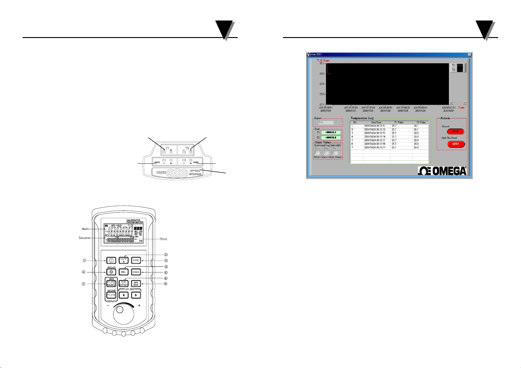
Top Side:
1. Output 1.
2. Output 2.
3. Input T1.
4. Input T2.
5. RS232 optical interface.
1
OPERATING INSTRUCTIONS
CL3515R
3
4. Record
4
2
5
Export
Both
Display drawing T1 and T2.
T1
Display drawing T1.
T2
Display drawing T2.
State Value
Setting Interval.
Start
Log
File type *.txt or *.xls
Quit
Exit
4
13
Page 3
CL3515R K/J/T/E/R/S/N/L/U/B/C Calibrator Thermometer
CL3515R K/J/T/E/R/S/N/L/U/B/C Calibrator Thermometer
7. “T1/T2 SOURCE” button
Pressing T1/T2 SOURCE to cycle through T1, T2 and SOURCE. In the main display
the blinking digit is the one to be adjusted, you can push the “” button to make
right or left shifts to the desired position. When incrementing to the utmost range of
the selected thermocouples, the LIMIT will show on the display.
SOURCE is to provide the output parameter settings. There are ten individual
temperature setting points in group 0, which can be set at your desired output point.
Use “” to shift the desired digit to be adjusted and rotate the knob to increase or
decrease the values you want to set. Press the T/C OFFSET to save the settings.
8. “OFFSET” button (Thermocouple offset adjust)
When the main display input is T1 or T2, and socket thermocouple is connected.
Press T/C OFFSET over two seconds the SET annouciator will appear on the right
side of display and enter the offset adjustment mode. And the blinking digit is the one
to be adjusted. Rotate the knob to the right increasing the values, to the left side
decreasing the values. The maximum range of the knob is ±5 centigrade. When
turning to the utmost range, it will appear LIMIT symbol on the left side of the
display and means that there is no further incrementing of the offset. Press the T/C
OFFSET over two seconds to save the settings.
9. “MIN/MAX” button
Press MIN/MAX button to enter the MIN/MAX recording mode and REC shows on
the display. The beeper emits a tone when a new minimum or maximum measurement
is recorded. Press the MIN/MAX button again to rotate through the current readings:
MAX: The highest measurement recorded.
MIN: The lowest measurement recorded.
MAX-MIN: The difference of the highest and the lowest measurement.
AVG: The average values of the measurements.
Press MIN/MAX button over two seconds to exit the function.
10. Knob usages in the settings
In the TYPE mode, it is used for thermocouples selection to make right or left shifts
to choose selectors. In the SOURCE mode, it is used to increase or decrease the
values of the output function.
11. PWM Group
Group 0 set
In the OUT mode, press T/C OFFSET over two seconds to set.
LCD display Set CLEAr press T1/T2 SOURCE button to clear data, display SEt 0-0.
In the main display the blinking digit is the one to be adjusted, you can push the
“” button to make right or left shifts to the desired position. Rotary knob to
increase or decrease the values. Press T1/T2 SOURCE to save the one step setting.
CL3515R can set 10 step, (Group 1 to 9 use software setting) press T/C OFFSET exit
group set mode.
IV Measurement
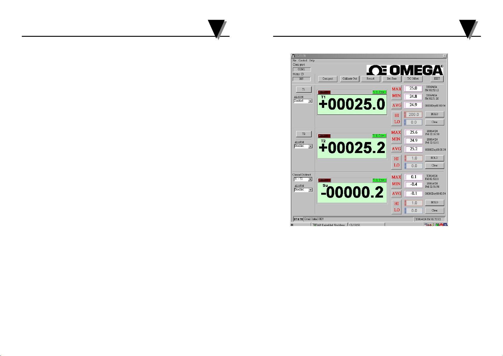
1. T1, T2, Channel Subtract (NONE, T1-T2, T2-T1)
ALARM function
Disable
Hi enable
Enables alarm Hi function, and it will become red flashing, when it is over Hi
setting value.
Lo enable
Enables alarm Lo function, and it will become blue flashing, when it is below Lo
setting value.
Both enable
To enable both Hi and Lo, and it will become red flashing, when it is over Hi setting
value, and it will become blue flashing when it is below Lo setting value.
HOLD
Hold the present reading.
Clear
Clear MAX, MIN, AVG recorded.
6
11
Page 4

CL3515R K/J/T/E/R/S/N/L/U/B/C Calibrator Thermometer
I CL3515R Software Install
CL3515R K/J/T/E/R/S/N/L/U/B/C Calibrator Thermometer
8
Click Next
Click Next
Click Next
Click Finish
II Uninstall
StarÆsettingÆcontrolÆnew/remove programÆCL3515R
9
Page 5

CL3515R K/J/T/E/R/S/N/L/U/B/C Calibrator Thermometer
CL3515R K/J/T/E/R/S/N/L/U/B/C Calibrator Thermometer
III Software Operating Instructions
StartÆProgramÆ CL3515R ÆCL3515R
Group out
In the OUT mode, press T/C OFFSET less than two seconds. Rotary knob to select
step. Press T/C OFFSET exit group out mode.
WARNING
To avoid possible electrical shock, disconnect the thermocouple connectors from
the thermometer before removing the cover.
MAINTENANCE
Battery Replacement
Power is supplied by a 9 volt battery. (NEDA 1604, IEC 6F22). The “ ” appears on
the LCD display when replacement is needed. To replace the battery, remove the two
screws from the back of the meter and lift off the battery cover. Remove the battery
from battery contacts.
Cleaning
Periodically wipe the case with a damp cloth and detergent, do not use abrasives of
solvents.
Periodically wipe the meter with soft and mild cloth. Do not use abrasive or solutions
to clean the meter.
Com Port Select
Select CL3515R Connection Com Port.
10
7
Page 6

CL3515R K/J/T/E/R/S/N/L/U/B/C Calibrator Thermometer
CL3515R K/J/T/E/R/S/N/L/U/B/C Calibrator Thermometer
2. Calibrate Out
3. Auto Send
Adjust output in real time.
Value
Set the output vale.
Send
Press “Send” CL3515R send out the output setting vale.
Group Item
Group 0 to Group 9.
Step Item Send
Step Item 0 to Step Item 9.
Forward
Select step forward.
Backward
Select step backward.
1. Power button “ ”
The “
power off function is disabled.
Remark: The meter will run self calibration when the meter starts.
2. Button “°C/°F/°K”
Press the °C/°F/°K button to cycle through temperature scale, °C, °F and °K.
3. Type Selection (the rmocouples)
Press the “type” button and the selected symbol will blink which means in the setting
mode.
Press “” button to make right shifts to cycle through
Press “” button to make left shifts to cycle through
Press the “type” button again to choose the selected thermocouple.
4. Backlight “
Pressing the button less than two seconds to turn on and pressing the button again less
than two seconds to turn off the backlight in the LCD. It will turn off after thirty
minutes without operation.
Auto power off
It is in the APO mode when the meter is turned on and will turn off the meter without
operation for fifteen minutes. Pressing the “ ” button over two seconds to cancel the
function. And pressing the “
5. “REL” button
The relative value function can be used for comparing the saved reference value with
other measurements. Press the “REL” button less than to store the current
measurement as the reference value, and press the “REL” over two seconds to disable
the function.
6. “HOLD” button
When HOLD mode is selected, the thermometer holds the present readings and stops
all further measurements. To activate the data hold mode, press the HOLD button,
and “HOLD” is displayed on the LCD. Pressing the HOLD button again cancels the
function, and the instrument will automatically resume measurements. When the Hold
key is activated, it will stop functions of the other entire key except Power and
Backlight.
” button turns the thermometer on or off. When entering REC mode, the
The measuring leads and calibration wires must be removed before
taking measurements, and you can get accurate calibration values.
K→J→T→E→R→S→N→L→U→B→C→mV.
K→mV→C→B→U→L→N→S→R→E→T→J.
” button
” button again to activate the APO function.
12
5
Page 7

CL3515R K/J/T/E/R/S/N/L/U/B/C Calibrator Thermometer
CL3515R K/J/T/E/R/S/N/L/U/B/C Calibrator Thermometer
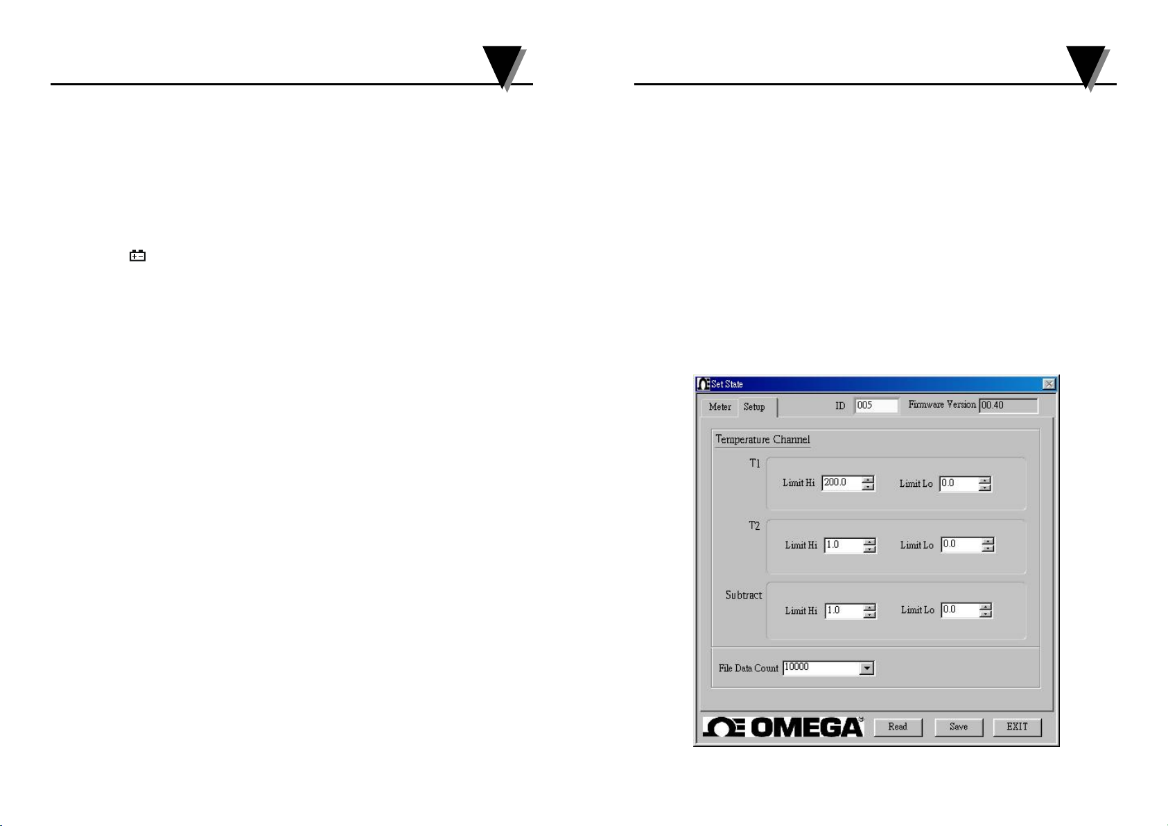
5. Set State
Read
Read out the groups reading of CL3515R.
Save
Make the setting value read in CL3515R.
EXIT
6. Meter
Temperature
Unit
°C, °F, °K
Type
K, J, T, E, R, S, N, L, U, B, C, mV
Group
Group Item
Group 0 to Group 9
Unit
°C, °F, °K
SPECIFICATIONS
ELECTRICAL
Temperature Scale:
Celsius or Fahrenheit user-selectable.
Measurement Range:
K-TYPE(0.1°) -200°C to 1372°C or -328°F to 2501°F
J-TYPE(0.1°) -210°C to 1200°C or -346°F to 192°F
T-TYPE(0.1°) -250°C to 400°C or -418°F to 752°F
E-TYPE(0.1°) -250°C to 1000°C or -418°F to1832°F
R-TYPE(1°) 0°C to 1767°C or 32°F to 3212°F
S-TYPE(1°) 0°C to 1767°C or 32°F to 3212°F
N-TYPE(0.1°) -200°C to 1300°C or -328°F to 2372°F
L-TYPE(0.1°) -200°C to 900°C or -328°F to 1652°F
U-TYPE(0.1°) -200°C to 600°C or -328°F to 1112°F
B-TYPE(1°) 600°C to 1820°C or 1112°F to 3308°F
C-TYPE(1°) 0°C to 2316°C or 32°F to 4200°F
Based on the ITS-90 temperature standard.
Accuracy:
K/J/T/E/L/U-TYPE
±(0.05% rdg + 0.5°C) -50°C to 1372°C
±(0.05% rdg + 1.0°C) -50°C to -250°C
±(0.05% rdg + 1.0°F) -58°F to 2501°F
±(0.05% rdg + 2.0°F) -58°F to -346°F
N-TYPE
±(0.05% rdg + 1.0°C) -50°C to 0°C
±(0.05% rdg + 0.5°C) 0°C to 1300°C
±(0.05% rdg + 2.0°F) -58°F to 32°F
±(0.05% rdg + 1.0°F) 32°F to 2372°F
R/S/B/C-TYPE
±(0.05% rdg + 2°C) 0°C to 1767°C
±(0.05% rdg + 4°F) 32°F to 3212°F
14
3
Page 8

CL3515R K/J/T/E/R/S/N/L/U/B/C Calibrator Thermometer
CL3515R K/J/T/E/R/S/N/L/U/B/C Calibrator Thermometer
Temperature Channel
T1 Hi, Lo Setting
T2 Hi, Lo Setting
Subtract Hi, Lo Setting
File Data Count
10000, 20000, 30000
8. T/C Offset
INTRODUCTION
This instrument is a 4 1/2 digit, compact-sized portable digital calibrator thermometer
designed to use external K/J/T/E/R/S/N/L/U/B/C type thermocouples as temperature
sensor. The thermometer features a dual thermocouple input, an adjustable T/C offset.
The thermocouples types comply with the (N.I.S.T. Monograph 175 Revised to ITS 90
standard).
SAFETY INFORMATION
It is recommended that you read the safety and operation instructions before using the
thermometer.
WARNING
To avoid electrical shock, do not use this instrument when working voltages at the
measurement surface over 24V AC or DC.
WARNING
To avoid damage or burns, do not make temperature measurement in microwave
ovens.
CAUTION
Repeated sharp flexing can break the thermocouple leads. To prolong lead life, avoid
sharp bends in the leads, especially near the connector.
Channel
T1
T2
T/C Offset
Offset ±5°C
16
1
 Loading...