

Omega Lift 50040, 50100 Operating Instructions Manual

Hydraulic Body Repair Kits
Model Capacity
50040 4 Ton
50100 10 Ton
㙀䴷࣋㺘
03D
Model 50040
⒀⑾⑥⑾⒀⒆⑩㈢
This is the safety alert symbol. It is used to alert you to potential personal injury hazards.
Obey all safety messages that follow this symbol to avoid possible injury or death.
!
Read this manual and follow all the Safety Rules and Operating Instructions before using this product.
© September 2017
㙀䴷࣋㺘
03D
Model 50100
SFA Companies
http://www.omegalift.com
50040-M0_092017
SAFETY AND GENERAL INFORMATION
Save these instructions. For your safety, read, understand, and follow the information provided with and on this
device before using. The owner and/or operator shall have an understanding of the device, its operating characteristics
and safety operating instructions before operating the equipment. The owner and/or operator shall be aware that use
and repair of this product may require special skills and knowledge. Instructions and safety information shall be read
to and discussed with the operator in the operator's native language, making sure that the operator comprehends
their contents, before use of this equipment is authorized. If any doubt exists as to the safe and proper use of this
device, remove from service immediately.
Inspect before each use. Do not use if abnormal conditions such as cracked welds, damaged, loose or missing
parts are noted. Any equipment that appears damaged in any way, is found to be worn, or operates abnormally shall
be removed from service until repaired. If the equipment has been or is suspected to have been subjected to an
abnormal load or shock, immediately discontinue use until inspected by a factory authorized repair facility (contact
distributor or manufacturer for list of authorized repair facilities). It is recommended that an annual inspection be
made by an authorized repair facility. Labels and Operator's Manuals are available from the manufacturer.
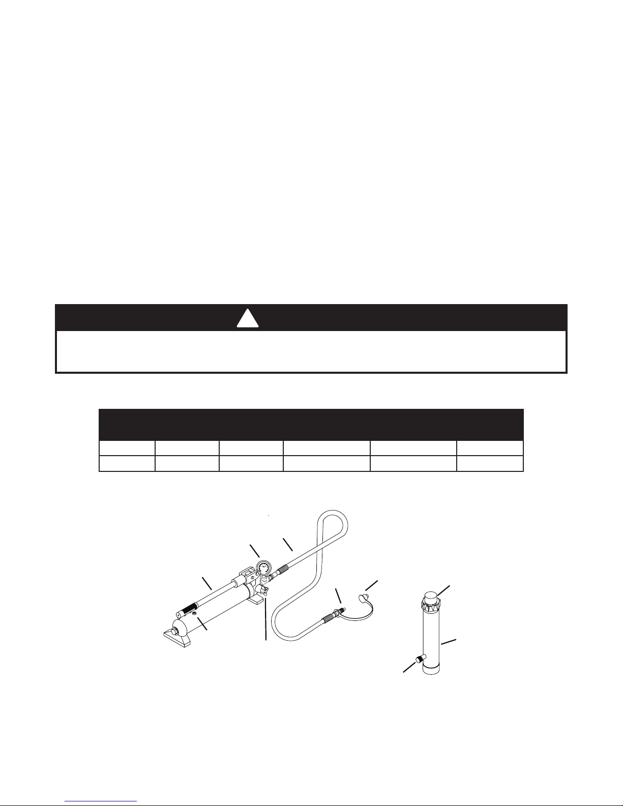
PRODUCT DESCRIPTION
Omega Hydraulic Body Repair Kits are designed to be used for pushing, spreading, and pressing of vehicle body
panels as well as various component parts and assemblies. A variety of attachments are included.
!
WARNING
When using extension tubes and/or offset attachments, reduce rated capacity by 50% for each tube or
offset attachment connected. See Replacement Parts section on pages 8 & 9 for identication of "offset"
attachments.
SPECIFICATIONS
Model
50040 8,000 psi 4 Ton 10-3/4” 15-5/8” 14
50100 10,000 psi 10 Ton 13-3/4” 19-3/4” 13
Pump
Capacity
Handle
Ram
Capacity
Gauge
Oil Filler
Screw
Closed Height Extended Height
Hose
Release Valve
Hose
Coupler
Ram Coupler
Ram
Dust Cover
Number of
Attachments
Plunger
Ram
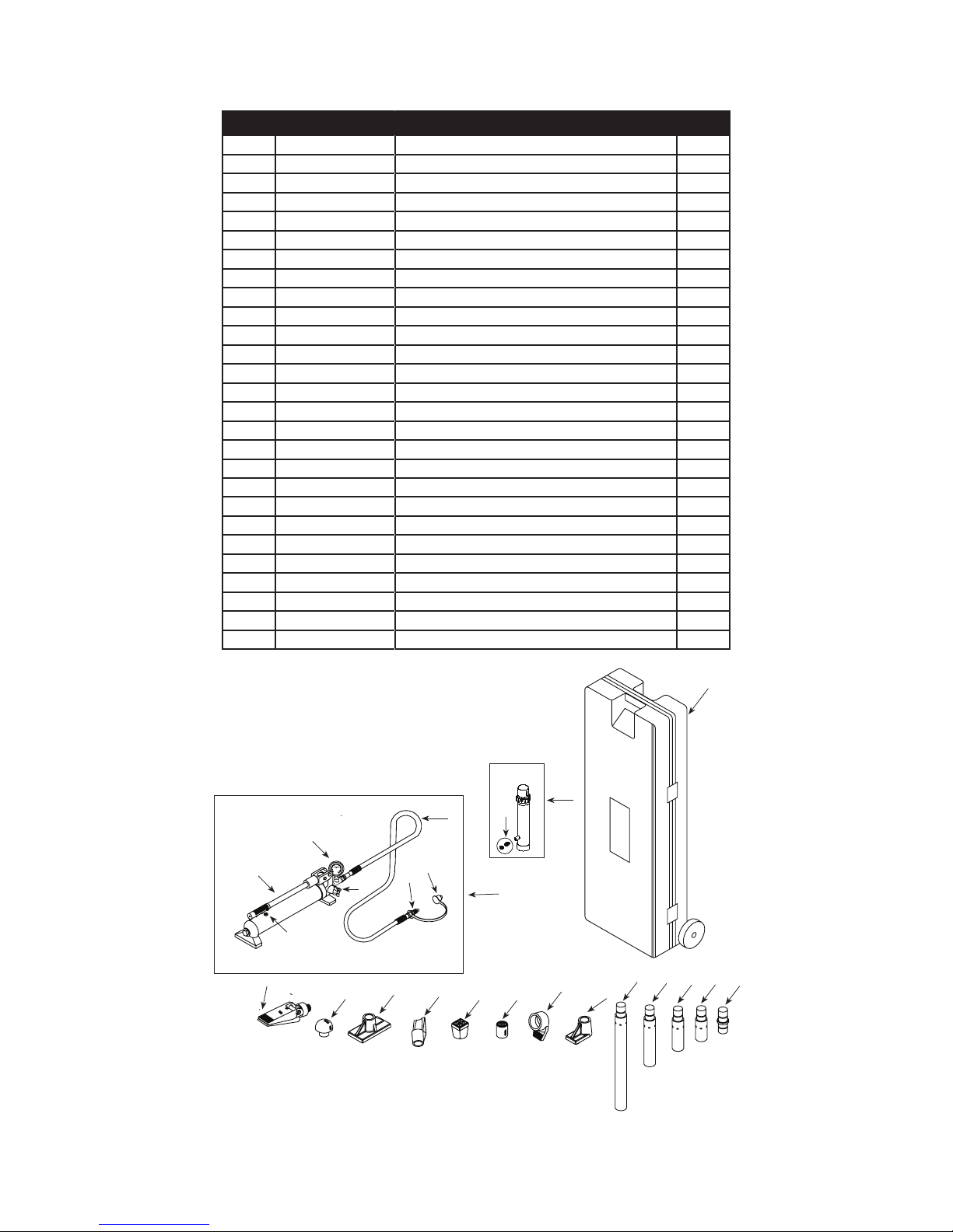
Figure 1 - 50040 and 50100 Components
2

!
WARNING
• Study, understand and follow all instructions before operating this device.
• Wear eye protective that meets ANSI Z87.1 and OSHA standards.
• Do not exceed the rated capacity.
• Use a pressure gauge that indicates pounds of force applied.
• When using extension tubes, position the shortest tube farthest from the cylinder.
• Do not subject the hose to extreme cold, heat, sharp surfaces, abrasion or impact.
• Do not allow the hose to kink, twist, curl or bend so tightly that it restricts uid ow.
• Make sure setup is stable and secure before performing any work.
• No alterations or modications shall be made to this product.
• Only components supplied with this kit shall be used with this kit.
• Failure to heed these markings may result in personal injury and/or property damage.
!
WARNING
ADDITIONAL SAFETY MESSAGES
• Avoid short runs of straight line tubing. Straight line runs do not provide for expansion and contraction due to
pressure and/or temperature changes.
• Long tubing runs should be supported by brackets or clips. Before operating the pump, all hose connections
must be tightened with the proper tools. Do not overtighten. Connections should only be tightened securely
and leak-free. Overtightening can cause premature thread failure or high pressure ttings to burst.
• Should a hydraulic hose rupture, burst or need to be disconnected, immediately shut off the pump and release
all pressure. Never attempt to grasp a leaking pressurized hose with your hands. The force of escaping
hydraulic uid is under high pressure and can inict injury.
• Do not pull, position or move setup by the hose. Doing so can damage the hose.
• Hoses also must not come in contact with corrosive materials such as battery acid, creosote-impregnated
objects and wet paint. Never paint a coupler or hose.
• Inspect each ram and coupler before each use to prevent unsafe conditions from developing. Inspect the hose
for wear.
• Do not use rams if they are damaged, altered or in poor condition.
• Do not use rams with bent or damaged coupler or damaged threads.
• Under certain conditions, the use of an extension with a hydraulic ram may not be advisable and could present
a dangerous condition.
• Avoid pinch points or crush points that can be created by the load or parts of ram.
• To help prevent material fatigue if the ram is to be used in a continuous application, the load should not exceed
85% of the rated capacity.
• Ram must be on a stable base capable of supporting the load while pushing or lifting.
• Ensure ram is fully engaged into/onto adapters, extension accessories.
• Use shims, friction material or constraints to prevent slippage of the base or load.
• Do not off-center loads on a ram. The load can tip or the ram can “kick out” and cause personal injury.
• Never try to disassemble a hydraulic cylinder. Refer repairs to qualied, authorized personnel.
• Keep ram clean at all times.
• When not is use, keep ram fully retracted.
• Use an approved, high-grade pipe thread sealant to seal all hydraulic connections. Teon tape can be used
if only one layer of tape is used and it is applied carefully (two threads back) to prevent the tape from being
introduced into hydraulic system. A piece of tape could travel through the system and obstruct the ow of uid
and adversely affect function.
3
BEFORE USE
1. Before using this product, read the owner's manual completely and familiarize yourself thoroughly with the
product, its components and recognize the hazards associated with its use.
2. Inspect before each use. Do not use if bent, broken, leaking or damaged components are noted.
3. Ensure all parts of your kit are included (ref. illustrations and parts list).
4. Remove dust caps and plugs from hose coupler and ram coupler.
5. Connect hose coupler to ram coupler, ensuring there are no uid leaks.
6. Locate and open release valve. Close release valve clockwise and pump handle until ram is fully extended, then
open release valve counter-clockwise until ram has fully retracted.
7. With ram fully retracted and release valve open, place pump in horizontal position. Open oil ller screw (located
on reservoir body). This will release air trapped within the reservoir. Reinstall oil ller screw.
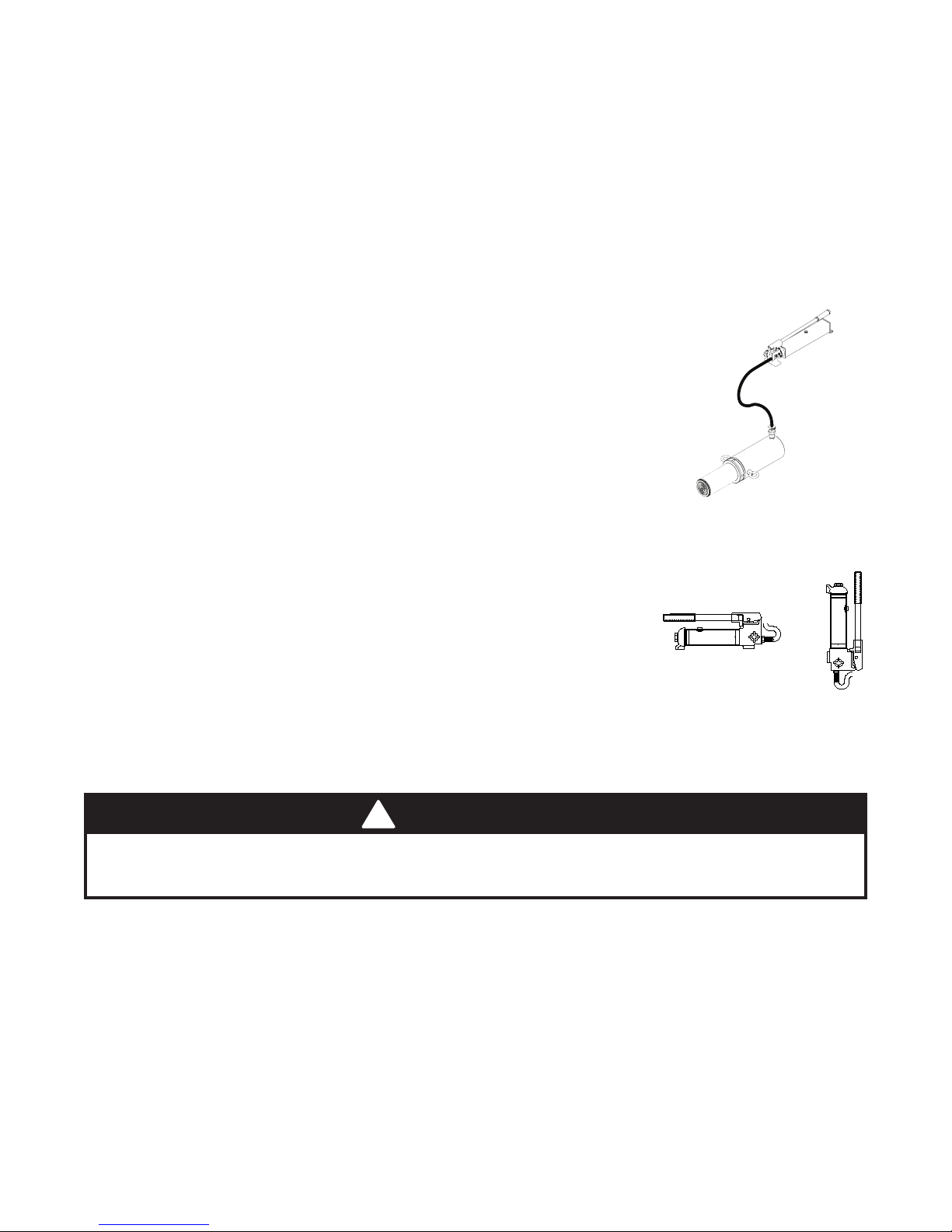
Bleeding Air from System
1. Bleed air from ram: Place pump at a higher elevation than the hose and ram
as shown in Figure 2. With the objective being to force air up stream to the
reservoir, close valve and extend ram as fast as possible. Open valve fully
allowing oil and air to return to reservoir. Repeat procedure two or three
times.
2. Bleed air from pump: With ram fully retracted, remove oil ller screw to let
pressurized air escape, then reinstall oil ller screw.
General Instruction
1. Pump may be used in horizontal or vertical position as illustrated (ref. Figure.
3).
2. Attachments must be fully engaged before applying load.
3. Ensure load is centrally applied to attachment or ram saddle. Do not attempt
off-center loading.
4. Always monitor the force applied to work piece by using a load cell and indicator, or monitor pressure developed in the ram by using an in-line pressure
gauge, then calculate the applied force using the formula:
F = P x A, where F = lbs force, P = pressure in psi, and A = effective
ram area in in2.
Ram Area of Model 50040 is: 0.998 in
Ram Area of Model 50100 is: 2.411 in
(ref. Load-Pressure Correlation chart on page 10)
5. If bowing or bending of ram or any attachment occurs during use, STOP IMMEDIATELY, release pressure and
reconsider application. Application may require higher capacity ram kit.
2
2
Figure 2 - Pump/ram air bleed
Figure 3 - Variable Position
When using extension tubes and/or offset attachments, reduce rated capacity by 50% for each tube or
offset attachment connected. See Replacement Parts section on pages 8 & 9 for identication of "offset"
attachments.
Basic Setup
The capacity of the body repair kit can be signicantly affected by the number of attachments used and the type
of load applied. The approximate load capacity of each function setup is illustrated on page 5. When two or more
extension tubes are used together, be sure to position the shorter tube furthest from the ram.
OPERATION
Applying Pressure to Work Piece:
1. Locate and close release valve by turning it clockwise until rmly closed. (Do not over tighten)
2. Operate by pumping handle. This will send uid from the pump reservoir into the high pressure hose assembly
and into the ram assembly.
3. Continue pumping until ram reaches desired position or overpressure situation is reached.
!
WARNING
4
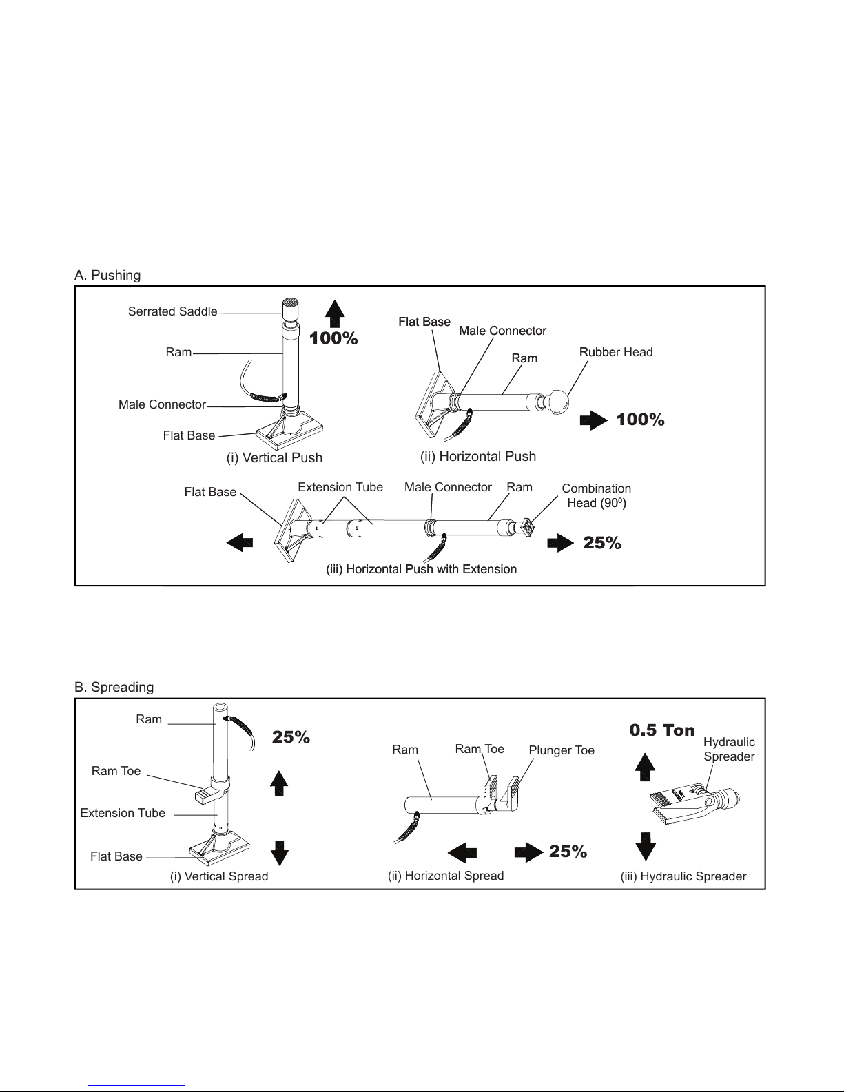
B. Spreading
(i) Vertical Spread
(ii) Horizontal Spread
(iii) Hydraulic Spreader
Ram Toe
Ram
Extension Tube
Flat Base
Ram Toe
Ram
Plunger Toe
Hydraulic
Spreader
25%
25%
0.5 Ton
Flat Base
Male Connector
Ram
Combination
Head (90
0
)
Extension Tube
(iii) Horizontal Push with Extension
Serrated Saddle
Ram
Male Connector
Flat Base
(i) Vertical Push
(ii) Horizontal Push
Flat Base
Male Connector
Ram
Rubber Head
100%
100%
25%
A. Pushing
Releasing Pressure on Work Piece:
Slowly, carefully turn the release valve counter-clockwise until ram retracts to desired position. Never turn release
valve more than 1/2 of a full turn. The ram return system is spring loaded and the release valve system is metered,
allowing controlled retraction of the ram.
5

MAINTENANCE
NOTICE: Use only good quality hydraulic jack oil. Avoid mixing different types of uid and NEVER use brake uid,
turbine oil, transmission uid, motor oil or glycerin. Improper uid can cause premature failure of the jack and the
potential for sudden and immediate loss of load. Premium hydraulic jack oil is recommended.
Adding oil
1. With ram fully lowered, set pump unit in its normal, level position. Locate and remove oil ller screw.
2. Fill until oil is within 3/8" of the oil ller screw hole opening, re-install oil ller screw.
Changing oil
For best performance and increased system life, replace the complete uid supply at least once per year.
1. With ram fully lowered, remove the oil ller screw from the pump reservoir as above.
2. Lay the pump on its side and drain the uid into a suitable container.
NOTICE: Dispose of hydraulic uid in accordance with local environmental regulations.
3. Set pump in its level upright position.
4. Fill with good quality jack oil to within 3/8" of the oil ller screw hole opening.
5. Perform Bleeding/Air from System procedure (page 4). Reinstall oil ller screw.
Lubrication
A coating of light lubricating oil to pivot points and hinges will help to prevent rust and assure that pump assemblies
move freely.
Cleaning
Periodically check the pump piston and ram for signs of rust or corrosion. Clean as needed and wipe with an oily
cloth.
NOTICE: Do not use sandpaper or abrasive material on ram or pump piston surfaces.
Storage
When not in use, store with the pump piston and ram fully retracted.
6

TROUBLESHOOTING GUIDE
The following information is intended as an aid in determining if problem exists. For repair service, contact Omega
service center in your area.
Symptom Possible Causes Corrective Action
Ram will not extend, or respond to
pressurized uid
Ram responds to pressurized
uid, but system does not maintain
pressure
Ram will not return uid to pump
Ram will not fully extend (cylinder
or spreader)
Poor performance
• Overload condition
• Release valve not closed
• Overload condition
• Release valve not closed
• Hydraulic unit malfunction
• Malfunctioning coupler, damaged
application
• Reservoir overlled
• Fluid level low • Secure load by other means, open
• Fluid level low
• Air trapped in system
• Remedy overload condition.
• Ensure release valve closed
• Remedy overload condition
• Ensure release valve closed
• Contact Service Center
• Secure load by other means. Open
release valve, depressurize pump
and hose, remove application and
replace coupler
• Secure load by other means, open
release valve, depressurize pump
and hose, remove application, then
drain uid to proper level
release valve, depressurize pump
and hose, remove application, then
add uid to proper level
• Ensure proper uid level
• Perform Bleeding Air from System
procedure (page 4)
7
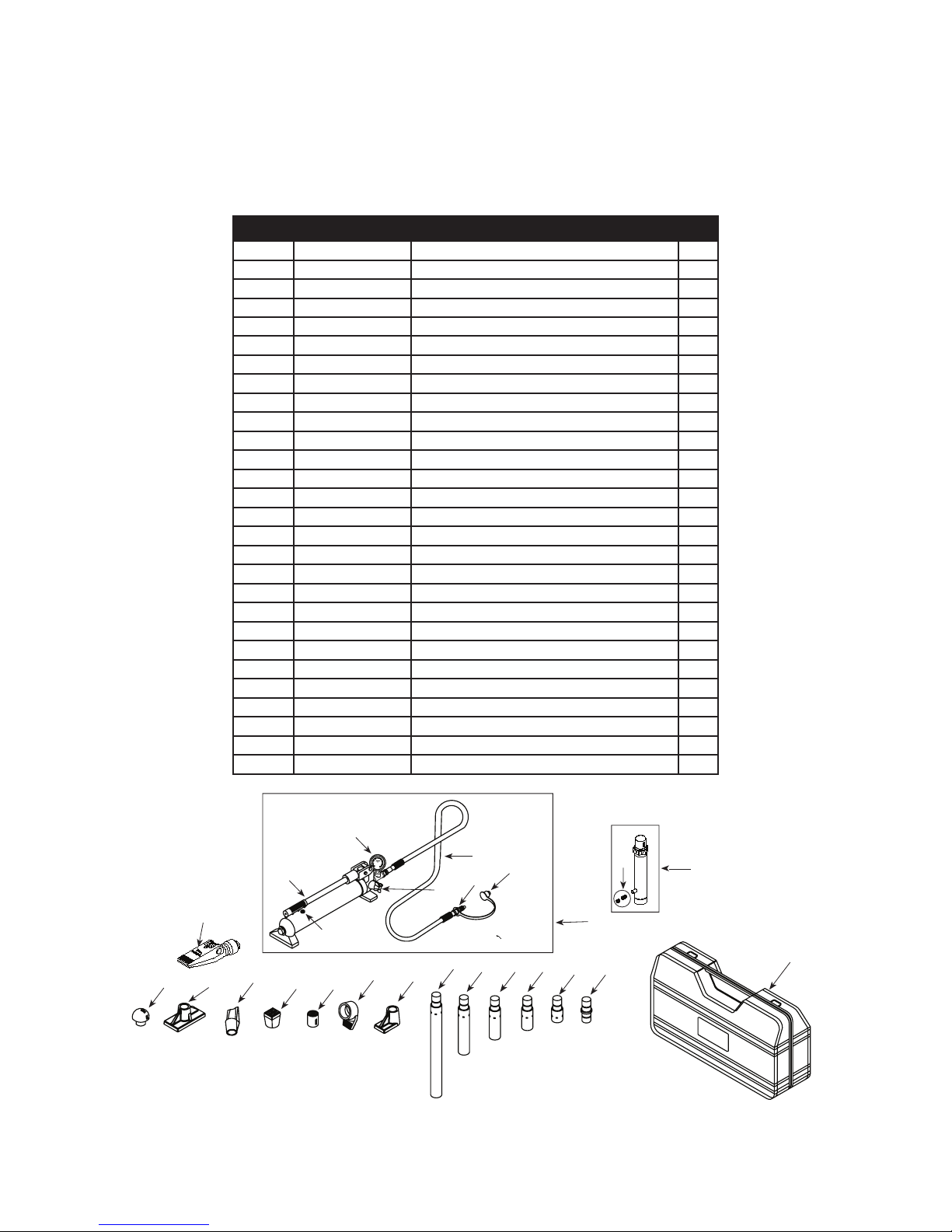
REPLACEMENT PARTS
Not all components of the jack are replacement items, but are illustrated as a convenient reference of location and
position in the assembly sequence. When ordering parts, give Model number, serial number and description below.
Call or write for current pricing: SFA Companies 10939 N. Pomona Ave. Kansas City, MO 64153, U.S.A.
Tel:(888)332-6419 Fax:(816)891-6599 e-mail: sales@omegalift.com Omega Website: http://www.omegalift.com
Model 50040
Item Part No. Description Qty
1 F040-90211-K01 Pump Assembly 1
2 F040-90009-K06 Ram Assembly 1
3 F040-22000-000 Hose Assembly (with coupler) 1
4 F040-00001-000 Blow Molded Case 1
5 F040-42000-000 Hydraulic Spreader (1000 lb. capacity) 1
6 F040-40002-000 Combination Head 1
7 F040-43000-000 Rubber Head 1
8 F040-40004-000 Ram Toe 1
9 F040-40005-000 Plunger Toe 1
10 F040-44000-000 Flat Base 1
11 F040-40003-000 Serrated Saddle 1
12 F040-40001-000 Wedge Head 1
13 F040-41600-000 Male connector 1
14 F040-41400-000 Extension Tube (3") 1
15 F040-41300-000 Extension Tube (6-1/8") 1
16 F040-41200-000 Extension Tube (8-1/2") 1
17 F040-41100-000 Extension Tube (16-1/2") 1
18 F040-41500-000 Extension Tube (19-1/2") 1
19 F040-90009-K05 Hose Coupler, Male 1
20 F040-90009-K04 Ram Coupler Assy, Female 1
21 F040-20012-000 Dust Cover - Hose 1
22 F040-90009-K03 Pump Handle 1
23 F040-90107-K02 Oil Filler Screw 1
24 F100-80001-000 Gauge 1
25 F040-21000-000 Release Valve Knob 1
- F0400S-85 Repair Kit -
- 50040-L0 Label 1
- 50040-M0 Manual 1
22
5
10
12
6
7
Figure 4 - Replacement Parts Illustration for Model 50040
23
24
3
21
19
25
18
8
11
9
17 16
15
1
14 13
20
2
4
8
1
3
24
17
16
15 14
13
12
11
10
4
9
8
7
6
5
2
21
19
18
22
⒀⑾⑥⑾⒀⒆⑩㈢
23
20
Model 50100
Item Part No. Description Qty
1 F100-90211-K01 Pump Assembly 1
2 F100-30000-000 Ram Assembly 1
3 F040-22000-000 Hose Assembly 1
4 F100-00004-000 Blow Molded Case 1
5 F040-42000-000 Hydraulic Spreader (1000 lb. capacity) 1
6 F100-40003-000 Combination Head (90
7 F100-42000-000 Rubber Head 1
8 F100-40005-000 Ram Toe (offset) 1
9 F100-40006-000 Plunger Toe (offset) 1
10 F100-40001-000 Flat Base 1
11 F100-40004-000 Serrated Saddle 1
12 F100-40002-000 Wedge Head (offset) 1
13 F100-41500-000 Male Connector 1
14 F100-41400-000 Extension Tube (4") 1
15 F100-41300-000 Extension Tube (10") 1
16 F100-41200-000 Extension Tube (18") 1
17 F100-41100-000 Extension Tube (27") 1
18 F040-90107-K02 Oil Filler Screw 1
19 F040-90009-K05 Hose Coupler, Male 1
20 F040-90009-K04 Ram Coupler Assy, Female 1
21 F040-20012-000 Dust Cover - Hose 1
22 F100-90009-K01 Pump Handle 1
23 F100-80001-000 Gauge 1
24 F040-21000-000 Release Valve Knob 1
- F1000S-85 Repair Kit -
- 50100-L0 Label ( not shown) 1
- 50040-M0 Manual 1
o
) 1
Figure 5 - Replacement Parts Illustration for Model 50100
9

LOAD - PRESSURE CORRELATION CHART
Models 50040 & 50100
Always monitor the force applied to work piece by using a load cell and indicator or you may monitor pressure
developed in the ram by using an in-line pressure gauge, then calculate the applied force using the formula:
F = P x A
where F = Force/ Load (lbs)
P = Hydraulic Working Pressure (psi) and
A = Ram Effective Area (in²)*
Load
(lbs)
Pressure (psi) of 4 Ton
Ram, where A = 0.998 in
Pressure (psi) of 10 Ton
2
Ram, where A = 2.411 in
1,000 1,002 415
2,000 2,004 830
3,000 3,006 1,244
4,000 4,008 1,659
5,000 5,010 2,074
6,000 6,012 2,489
7,000 7,014 2,903
8,000 8,016 3,318
9,000 3,733
10,000 4,148
11,000 4,562
12,000 4,977
13,000 5,392
14,000 5,807
15,000 6,221
16,000 6,636
17,000 7,051
18,000 7,466
19,000 7,881
20,000 8,295
2
*For Model 50040, A = 0.998 in²; For Model 50100, A = 2.411 in²
Example 1
Model 50040 exerting 5,000 lbs of force will require what pressure?
Pressure = Force Ram Effective Area = 5,000 lbs 0.998 in² = 5,010 psi
Example 2
Model 50100 operating at 6,000 psi will generate what force?
Force = Pressure x Ram Effective Area = 6,000 psi x 2.411 in2 = 14,466 lbs
10

Notes
SFA Companies
10939 N. Pomona Ave. Kansas City, MO 64153
888-332-6419
sales@omegalift.com
11
 Loading...