

Omega Lift 23225 User Manual
Air/Hydraulic Axle Jack
Model Capacity
23225 25 Ton
This is the safety alert symbol. It is used to alert you to potential personal injury hazards.
Obey all safety messages that follow this symbol to avoid possible injury or death.
!
Read this manual and follow all the Safety Rules and Operating Instructions before using this product.
© March 2016
U.S. Patent No. 6,012,377
SFA Companies
23225-M0_032017

Table of Contents
SAFETY AND GENERAL INFORMATION 3
PRODUCT DESCRIPTION 3
PREPARATION 3
Before Use 3
Venting Trapped Air Procedure 3
SPECIFICATIONS 4
OPERATION 5
Lifting 5
Lowering 5
MAINTENANCE 6
Adding/ Changing Oil 6
Lubrication 6
Cleaning 6
Storage 6
TROUBLESHOOTING 6
REPLACEMENT PARTS 7
LIFETIME MANUFACTURER’S WARRANTY 9
FRANÇAIS 10
ESPAÑOL 18

SAFETY AND GENERAL INFORMATION
Save these instructions. For your safety, read, understand, and follow the information provided with and on this
device before using. The owner and/or operator shall have an understanding of the device, its operating characteristics
and safety operating instructions before operating the equipment. The owner and/or operator shall be aware that use
and repair of this product may require special skills and knowledge. Instructions and safety information shall be read
to and discussed with the operator in the operator's native language, making sure that the operator comprehends
their contents, before use of this equipment is authorized. If any doubt exists as to the safe and proper use of this
device, remove from service immediately.
Inspect before each use. Do not use if abnormal conditions such as cracked welds, damaged, loose or missing
parts are noted. Any equipment that appears damaged in any way, is found to be worn, or operates abnormally shall
be removed from service until repaired. If the equipment has been or is suspected to have been subjected to an
abnormal load or shock, immediately discontinue use until inspected by a factory authorized repair facility (contact
distributor or manufacturer for list of authorized repair facilities). It is recommended that an annual inspection be
made by an authorized repair facility. Labels and Operator's Manuals are available from the manufacturer.
PRODUCT DESCRIPTION
Hydraulic Axle Jacks are designed to lift, but not support, rated capacity partial vehicle loads consisting of one end
of a vehicle. Immediately after lifting, support loads with a pair of appropriately rated jack stands.
PREPARATION
Reference Replacement Parts on our website www.omegalift.com . Assemble, align and insert the handle assembly
and handle position bar into the handle sleeve, then tighten the bolt on handle sleeve to prevent accidental removal
of handle while in use.
Before Use
1.
Verify that the product and application are compatible, if in doubt call Omegalift Technical Service (888) 332-6419.
2. Before using this product, read the operator's manual completely and familiarize yourself thoroughly with the
product, its components and recognize the hazards associated with its use.
3. To familiarize yourself with basic operation, locate and turn the release valve (handle knob):
a. Clockwise until rm resistance is felt to further turning. This is the ‘CLOSED’ release valve position used to
raise the load.
b. Counter-clockwise, no more than 1 full turn from closed position. This is the ‘OPEN’ release valve position used
to lower the load. The further the release valve is turned counter-clockwise, the faster the load descends.
4. With ram fully lowered, remove the oil ller screw. Check oil level. Proper oil level should be just below the rim of
the opening. Reinstall the oil ller screw.
5. Pour a teaspoon of good quality air tool lubricant into the air supply inlet of the lift control valve. Connect to air
supply, then squeeze the lift control valve for 3 seconds to evenly distribute lubricant.
NOTICE: These models are equipped with 1/4" NPT air couplers. If installing a different air coupler, ensure thread
tape or compound is used on connections. To ensure dependable, trouble free operation an inline air dryer and oiler
is recommended.
6. Ensure that jack rolls freely. Raise and lower the unloaded ram throughout the lifting range before putting into
service to ensure the jack operates smoothly. Replace worn or damaged parts and assemblies with Omegalift
authorized replacement parts only.
Venting Trapped Air Procedure
1. Open oil ller plug.
2. Open release valve.
3. Activate air motor to vent air.
4. Remove set screw and use a screw driver to hold down check ball while very slowly pumping air motor until oil
exiting from screw hole is steady without bubbles.
5. Reinstall set screw approximately two turns into hole (do not fully tighten).
6. Activate air motor a few additional times to vent air, while slowly tightening set screw. Ram should start to raise
as screw is fully tightened.
7. Check oil level and reinstall ller screw.
3
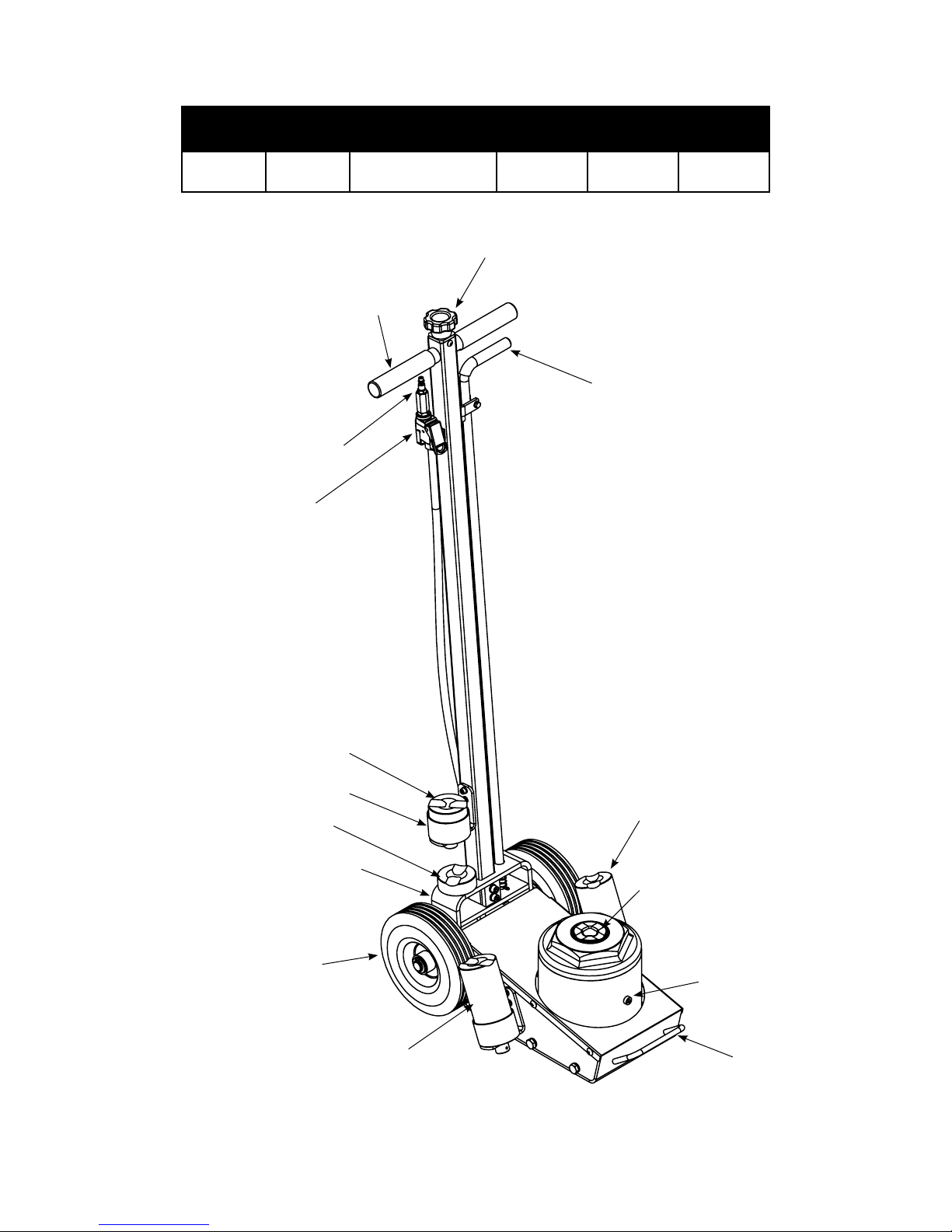
SPECIFICATIONS
Model Capacity Jack Size (L x W)
23225 25 Ton 21-7/8" x 15" 9-1/8" 22" 5-7/8"
Air Supply Inlet,
Lift Control
1/4NPT
Valve
Handle
Min.
Height
Handle Knob
(release valve)
Max.
Height
Handle
Position
Release
Hyd.
Range
Adapter, 2-1/2"
Adapter Holder
Adapter, 1"
Handle Sleeve
Wheel
Adapter, 6"
Figure 1 - Typical Truck Jack Nomenclature
4
Adapter, 7"
Saddle
Oil Filler
Screw
Carrying
Handle
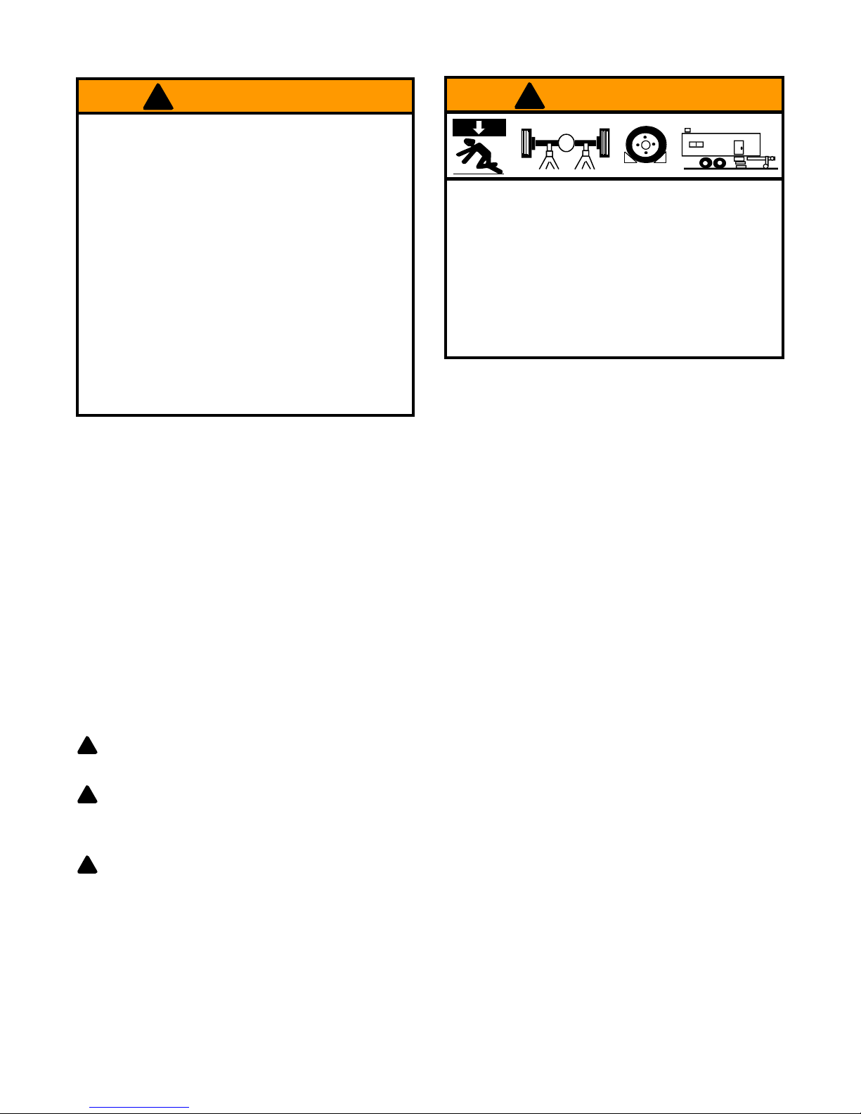
! WARNING
! WARNING
• Study, understand, and follow all
before operating this device.
instructions
X
• Do not exceed rated capacity.
• Use only on hard, level surface.
• Lifting device only. Immediately after lifting,
support the vehicle with appropriate means.
• Do not move or dolly the vehicle while on the
jack.
• Lift only on areas of the vehicle as specied by
the vehicle manufacturer.
• No alterations shall be made to this product.
• Failure to heed these markings may result in
personal injury and/or property damage.
OPERATION
(ref. Figure 1)
Lifting
NOTICE: These jacks are equipped with handle position locks. To adjust the handle, release lock device by pulling the
lever up, lever is spring loaded and will lock into desired position. Ensure lever locking mechanism is fully engaged
before leaving.
To avoid crushing and related injuries:
•
Never work on, under or around a load supported
only by hydraulic jack.
•
Always use adequately rated jack stands.
• Chock each unlifted tire in both directions.
• Do not use this device to lift, level, lower, support nor
move a house, mobile home, travel trailer, camper or
any building structure.
• Be alert and sober when using this product. Do not
operate under the inuence of drugs or alcohol.
1. Connect adequate air source to the air supply inlet.
2. Follow the vehicle manufacturer’s recommended guidelines for lifting. Engage the emergency brake and chock
each unlifted wheel in both directions to prevent inadvertent vehicle movement.
3.
Close the release valve by turning the handle knob clockwise until rm resistance is felt.
4. Center jack saddle under lift point, then squeeze the lift control valve until saddle contacts the lift point. To lift,
continue squeezing the lift control valve until load reaches desired height. Simply release your grip on the lift
control valve to end lift event.
5. Transfer the load to appropriately rated jack stands.
WARNING: Never wire, clamp or otherwise disable the lift control valve to function by other than
!
operator's hand.
WARNING: Only attachments and/or adapters supplied by the manufacturer shall be used.
!
Lowering
WARNING: Clear all tools and personnel before
!
knob is turned counter-clockwise, the faster the load will descend. Maintain control of load at all times.
1. Raise load high enough to clear jack stands.
2.
Remove jack stands carefully.
3. Slowly turn handle knob counter-clockwise, but no more than 1 full turn. If the load fails to lower:
a. Use another jack to raise vehicle high enough to reinstall jack stands.
b. Remove the malfunctioning jack and then the jack stands.
c.
Use the functioning jack to lower
4. After removing jack from under vehicle, fully retract the jack to reduce ram exposure to rust and contamination.
vehicle.
lowering load. Open release valve slowly. The further handle
5

MAINTENANCE
NOTICE: Use only good quality hydraulic jack oil. Avoid mixing different types of uid and NEVER use brake uid,
turbine oil, transmission uid, motor oil or glycerin. Improper uid can cause premature failure of the jack and the
potential for sudden and immediate loss of load. Premium hydraulic jack oil is recommended. Upon electronic
registration you will receive automatic maintentance update emails reminding you of service for your unit.
Adding/ Changing Oil
For best performance and longest life, replace the complete uid supply at least once per year.
1. With saddle fully lowered remove cover plate, then oil ller screw.
2. Lay jack on its side and drain uid into a suitable container.
NOTICE: Dispose of hydraulic uid in accordance with local environmental regulations.
3. Set jack in its upright, level position.
4. Fill with oil. Proper oil level is just below the rim of the opening. Reinstall the oil ller screw.
5. Perform Bleeding/Venting Trapped Air procedure (page 2).
Lubrication
A periodic coating of light lubricating oil to pivot points, axles and hinges will help to prevent rust and assure that
wheels move freely and the pump functions smoothly. To help ensure trouble free operation, an inline air dryer and
oiler is recommended.
Cleaning
Periodically check the ram for signs of rust or corrosion. Clean as needed and wipe with an oily cloth.
NOTICE: Do not use sandpaper or abrasive material on ram and pump piston surfaces.
Storage
When not in use, store the jack with saddle fully lowered.
TROUBLESHOOTING
Symptom Possible Causes Corrective Action
• Release valve not tightly closed
Jack will not lift load
Jack will lift, but not maintain pressure
Jack will not lower after unloading • Reservoir overlled • Drain uid to proper level
Poor lift performance
Will not lift to full extension • Fluid level low • Ensure proper uid level
• Load is too heavy
• Air supply inadequate
• Release valve not tightly closed
• Hydraulic unit malfunction
• Fluid level low
• Air trapped in system
• Ensure release valve tightly closed
• Consider higher capacity jack
• Ensure adequate air supply
• Ensure release valve tightly closed
• Discontinue use, contact Omegalift
technical service
• Ensure proper uid level
• Follow Bleeding/Venting Trapped
Air procedure on page 3
6
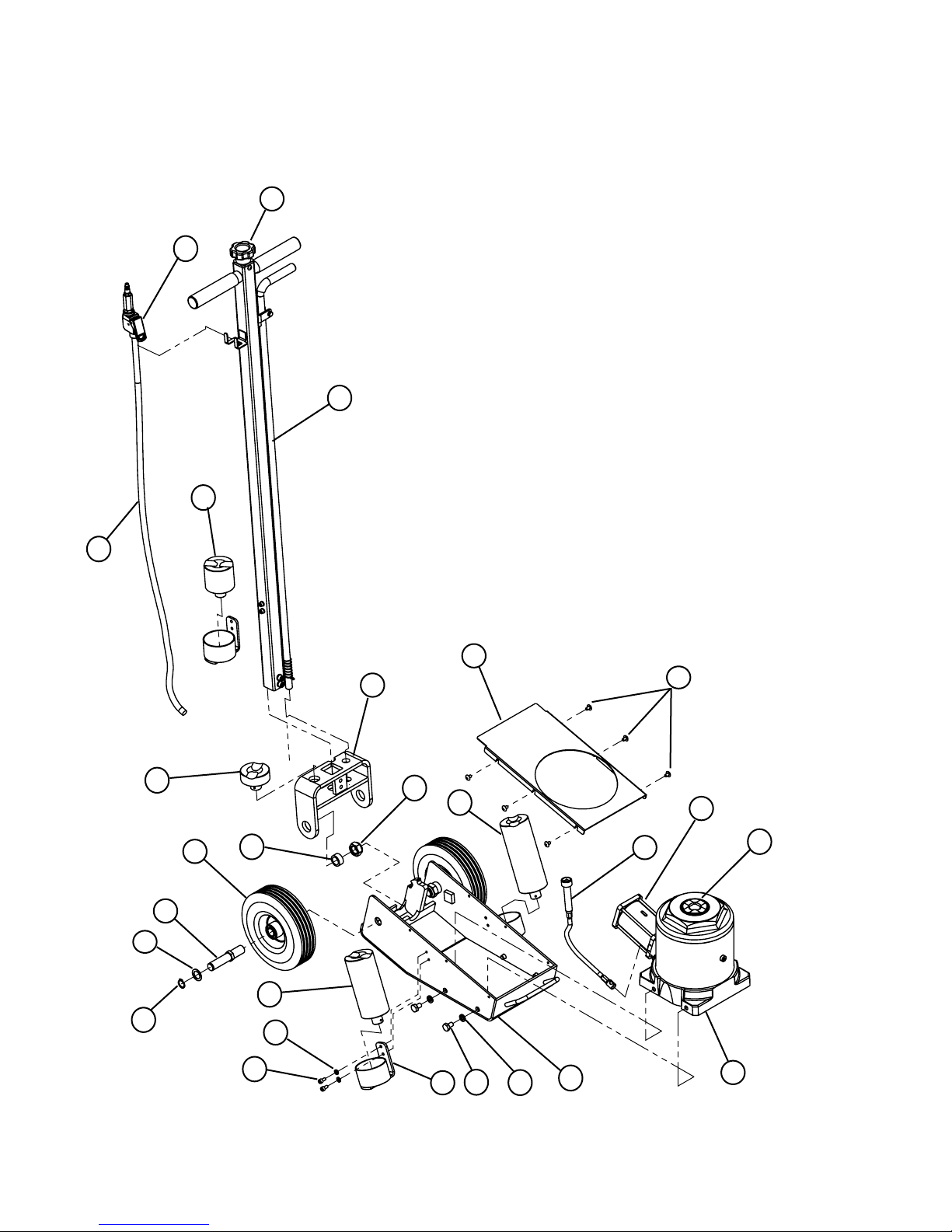
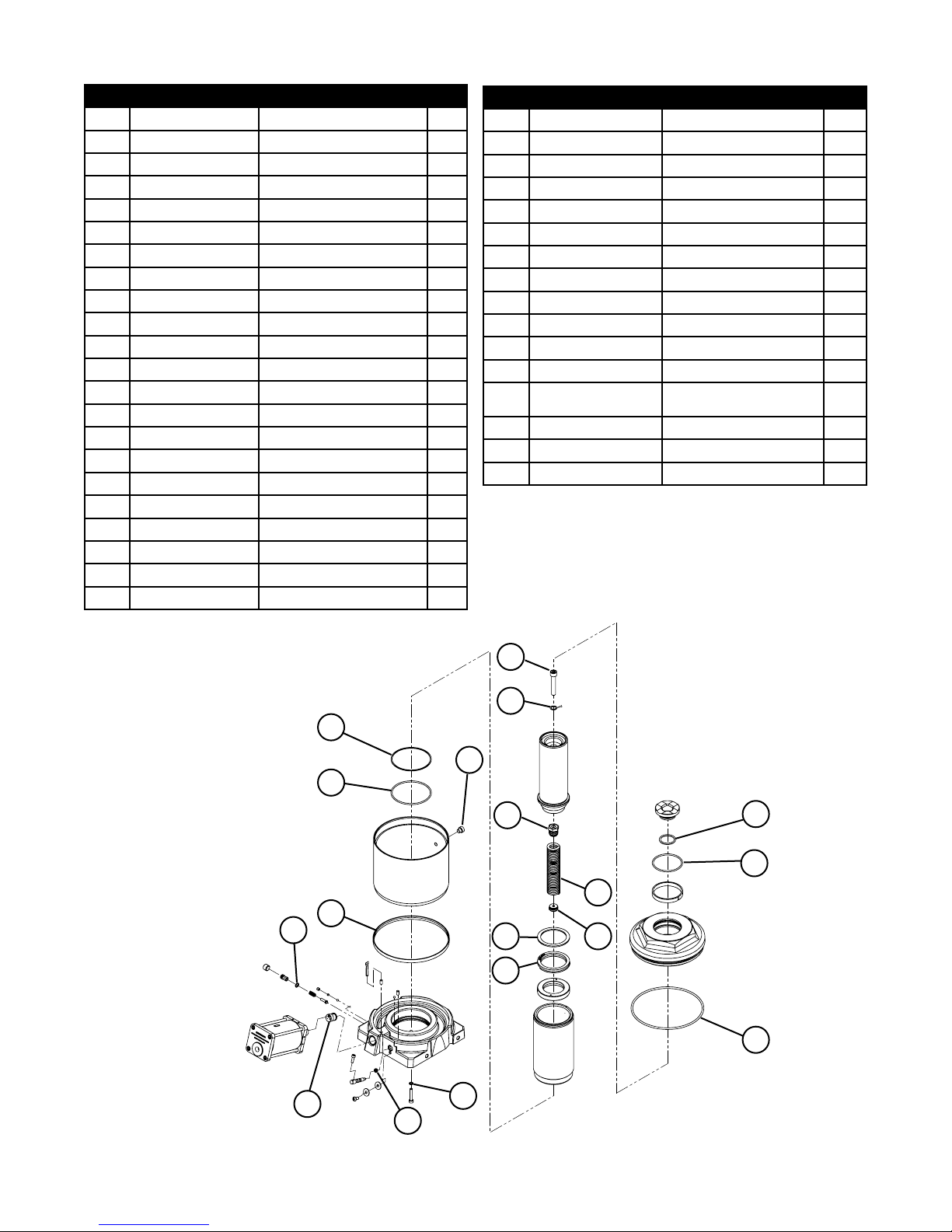
REPLACEMENT PARTS (ref. page 7 & 8)
Not all components of the jack are replacement items, but are illustrated as a convenient reference of location and
position in the assembly sequence. When ordering parts, please give the Model number, part number and parts
description. Call or write for current pricing: SFA Companies 10939 N. Pomona Ave. Kansas City, MO 64153, U.S.A.
Tel: (816) 891-6390 Fax: (816) 891-6599 E-Mail: sales@omegalift.com
11
13
10
16
12
24
25
15
5
9
27
18
6
7
26
17
22
19
3
4
14
23
21
8
Figure 2 - Replacement Parts Illustration
20
7
1
2
Item Part No.
1 A26-3-3000-102
2 A26-1-1000-100
3 A27-3-2000-104
4 A07-3-3300-307
5 A26-6-3220-104
6 A22-4-3400-106
7 A26-6-3230-107
8 A26-3-3200-100
9 A26-3-2104-109
10 A26-4-2100-107
11 421-6-2202-209
12 A26-4-2040-105
13 A24-3-2050-108
14 A26-6-1103-100
15 A26-6-1104-102
16 A26-6-1105-104
17 A26-6-1106-106
18 A26-6-1107-108
19 612-1-0060-101
20 605-3-0100-203
21 653-1-0100-014
22 605-3-0060-005
Description
Frame Assembly
Hydraulic Unit Assembly
Air Motor
Release Valve Cable
Cover Plate
Wheel
Axle
Adapter Holder
Handle Socket
Handle Assembly
Handle Knob
Air Hose Assembly
Air Control Valve
Saddle
1" Adapter
2-1/2" Adapter
6" Adapter
7" Adapter
Phillips Head Screw
Lock Washer
Bolt
Lock Washer
Qty
1
1
1
1
1
2
2
3
1
1
1
1
1
1
1
1
1
1
6
4
4
4
Item Part No.
23 649-1-0060-113
24 511-3-0202-046
25 667-5-0190-002
26 A26-6-5202-102
27 661-2-0200-100
28 324-4-1900-208
29 A20-3-1500-100
30 649-1-0100-302
31 515-3-0115-104
32 H30-6-2100-108
33 512-2-0320-209
34 H24-5-2100-203
- A26-3-9900-108
- A27-3-9901-107
- 23225-M0
- 23225-L0
Description
Bolt
Washer
Retaining Ring
Bushing
Lock Nut
Filler Screw Assembly
Hydraulic Cartridge
Bolt
Washer
Spring Fixed Block
Return Spring
Spring Fixed Block
Hydraulic Seal Kit (incl. 28,
31, A~K)
Air Motor Seal Kit
Owner's Manual
Labels
Qty
4
2
2
2
2
1
1
1
1
1
1
1
1
1
1
1
30
31
F
28
G
32
A
B
33
H
K
E
34
D
C
29
I
J
8
 Loading...