

Page 1
COD. 04067 Omega 16.01.2017 REV0
We ask that you carefully read the instructions within this booklet to enable you to abtain quality results from the outset.
The appliance must be installed only by an authorised person in compliance with the instructions provided. The manufacturer
declines all responsability for improper installation which may harm persons and animals and damage property.
The appliance must be used for the purpose for which it was expressly designed. Any other use (eg heating rooms) is considered to
be improper and consequently dangerous. The manufacturer declines all responsability for damage resulting from improper and
irresponsible use.
The manufacturer shall not be held responsible for any inaccuracies in this handbook due to printing or transcription errors. The
designs in the figures are purely indicative.
The manufacturer also reserves the right to make any modifications to the products as may be considered necessary, useful or in the
interests of the user, without jeopardizing the main functional and safety features on the products themselves.
If your hotplate requires service, please contact your local customer service centre or your nearest OMEGA agent listed at the back
of this booklet.
PLEASE READ THIS MANUAL BEFORE
INSTALLING THE HOTPLATE.
Dear Customer
Thank you for purchasing a OMEGA Cooktop.
You will find that the clean lines and modern look of your OMEGA Cooktop blends perfectly with your kitchen
décor. It is easy to use and performs to a high standard.
OMEGA also makes a range of products that will enhance your kitchen such as ovens, rangehoods, dishwashers,
microwaves, sinks and taps.
There are models to complement your new OMEGA Cooktop.
Of course we make every effort to ensure that our products meet all your requirements, and our Customer
Relations department is at your disposal, to answer your questions and to listen to all your suggestions (see back
cover of manual).
Please complete the warranty section of this manual and keep your receipt as proof of purchase. Retain all
documents relating to the purchase of this products.
OMEGA is committed to providing increasingly efficient products that are easy to use, respect the environment
and are attractive and reliable.
OMEGA
USE, INSTALLATION AND MAINTENANCE
INSTRUCTIONS FOR BUILT-IN HOTPLATE
MOD: OCG63FXX
MOD: OCG64FXX
MOD: OCG95FXX
Page 2
2
WARNING
Children less than 8 years of age shall be kept away unless
continuously supervised.
This appliance can be used by children aged from 8 years and
above and persons with reduced physical, sensory or mental
capabilities or lack of experience and knowledge if they have
been given supervision or instruction concerning use of the
appliance in a safe way and understand the hazards involved.
Children shall not play with the appliance.
Cleaning and user maintenance shall not be made by children
without supervision.
During operation the work surfaces of
the cooking area become very hot: keep
children away!
In case of hotplate glass breakage:
●shut immediately off all burners and any electrical heating element and
isolate the appliance from the power supply;
●do not touch the appliance surface;
●do not use the appliance.
Call the Sales Service Centres
Page 3
3
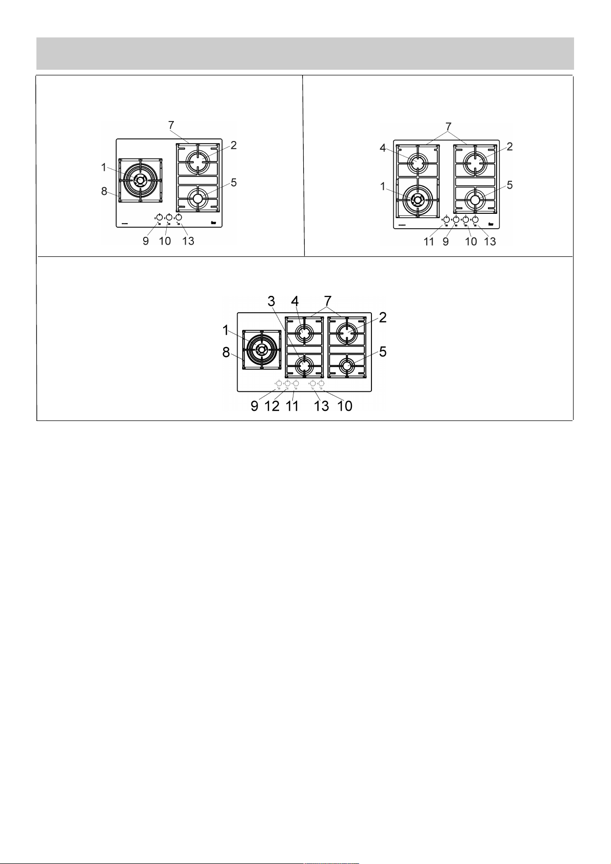
DESCRIPTION OF HOBS
Natural U-LPG
1 Duble Crown gas burner 14.5 MJ/h 12.6 MJ/h
2 Rapid gas burner 12.0 MJ/h 10.4 MJ/h
3 Semirapid reduced gas burner 5.4 MJ/h 4.86 MJ/h
4 Semirapid gas burner 7.1 MJ/h 6.3 MJ/h
5 Auxiliary gas burner 4.1 MJ/h 3.6 MJ/h
7 Pan stands
8 Pan stands Duble Crown
9 Burner n° 1 control knob
10 Burner n° 5 control knob
11 Burner n° 4 control knob
12 Burner n°3 control knob
13 Burner n°2 control knob
Attention: this appliance has been manufactured for domestic use only and it employment by
private person.
MOD: OCG63FXX
MOD: OCG64FXX
MOD: OCG95FXX
Page 4
4
USE
FIG. 1 FIG. 2
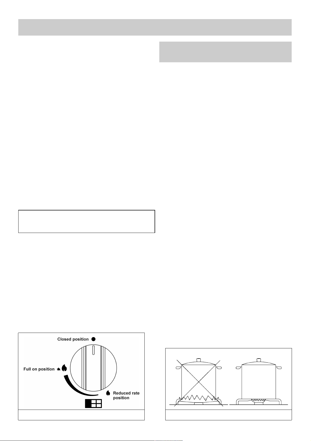
1) BURNERS
A diagram is screen-printed above each knob on the
front panel. This diagram indicates to which burner
the knob in question corresponds. After having
opened the gas mains or gas bottle tap, light the
burners as described below:
- automatic electrical ignition
Push and turn the knob corresponding to the
required burner in an anticlockwise direction until it
reaches the full on position (large flame fig. 1), then
depress the knob.
- Lighting burners equipped with flame failure
device
The knobs of burners equipped with flame failure
device must be turned in an anticlockwise direction
until they reach the full on position (large flame fig. 1)
and come to a stop. Now depress the knob in
question and re peat the previously indicated
operations.
Keep the knob depressed for about 10 seconds once
the burner has ignited.
Note: you are advised not to try and light a
burner if the flame divider (burner Cap) is not
correctly placed
HOW TO USE THE BURNERS
Bear in mind the following indications in order to
achieve maximum efficiency with the least possible
gas consumption:
- Use adequate pans for each burner (consult the
following table and fig. 2).
- When the pan comes to the boil, set the knob to
the reduced rate position (small flame fig. 1).
- Always place a lid on the pans.
- Use only pan with a flat bottom.
WARNINGS:
- Burners with flame failure device may only be
ignited when the relative knob has been set to
the Full on position (large flame fig. 1).
- Matches can be used to ignite the burners in a
blackout situation.
- Never leave the appliance unattended when the
burners are being used. Make sure there are no
children in the near vicinity. Particularly make
sure that the pan handles are correctl y
position ed and keep a check on foods
requiring oil and grease to cook since these
products can easily catch fire.
- DO NOT SPRAY AEROSOLS IN THE VICINITY OF
THIS APPLIANCE WHILE IT IS IN OPERATION.
- Should a crack appear on the surface of the glass,
disconnect the appliance from the electricity
supply immediately.
- Do not place pans with an unstable or deformed
bottom on the burner, as these may tip or spill their
contents, causing accidents.
- DO NOT USE OR STORE FLAMMABLE
MATERIALS NEAR THIS APPLIANCE.
- Do not use the hob as a work surface.
- This product is not to be installed in marine
crafts, caravans, or mobile homes.
- Containers wider than the unit are not
recommended.
- Avoid scraping the pans on the glass surface,
as the surface may become scratched.
- DO NOT MODIFY THIS APPLIANCE.
- DO NOT USE AS A SPACE HEATER.
Burners
Power ratings
Pan Ø
in cm
Natural U-LPG
Ultra rapid/WOK 14.5 MJ/h 12.6 MJ/h
24 - 26
Rapid 12.0 MJ/h 10.4 MJ/h
20 - 22
Semirapid reduced 5.4 MJ/h 4.86 MJ/h
16 - 18
Semirapid 7.1 MJ/h 6.3 MJ/h
16 - 18
Auxiliary 4.1 MJ/h 3.6 MJ/h
10 - 14
In the event of the Burner flames being accidentally
extinguished, turn off the burner control and do not
attempt to re-ignite the burner for a least 1 minute.
Burner designation:
Page 5
5
USE
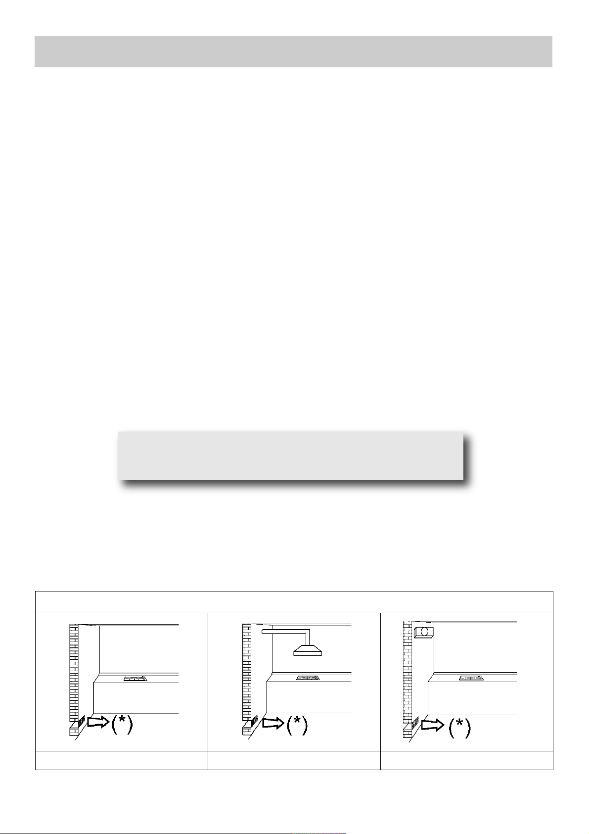
FIG. A FIG. B FIG. C
(*) Air inlet - minimum section 100 cm
2
WARNINGS AND ADVICE FOR THE USER:
use of a gas cooking appliance produces heat and moisture in the room in which it is installed. The
room must therefore be well ventilated by keeping the natural air vents clear (fig. A) and by
activating the mechanical aeration device (suction hood or electric fan fig. B and fig. C).
Intensive and lengthy use of the appliance may require additional ventilation. This can be achieved
by opening a window or by increasing the power of the mechanical exhausting system if installed.
Do not attempt to change the technical characteristics of the product because it can be dangerous.
-The appliance is not intended for use by persons (including children ) with reduced physical
sensory or mental capabilities, or lack of experience and knowledge, unless they have been given
supervised or instruction concerning use of the appliance by a responsible person for their
safely.
- Young children should be supervised to ensure that they do not play with the appliance.
Abnormal Operation:
Any of the following are considered to be abnormal operation and may require servicing:
- yellow tipping of the hob burner flame.
- Sooting up of cooking utensils.
- Burners not igniting properly.
- Burners failing to remain alight.
- Burners extinguished by cupboard doors.
- Gas valves which are difficult to turn.
Note: continuous use could cause the burners to change colour
due to the high temperature.
Page 6

6
USE
WARNINGS AND ADVICE FOR THE USER:
- Do not attempt to change the technical characteristics of the product because it can be dangerous.
- If you decide longer use this appliance any more (or replace an old model), before disposing of it,
make it inoperative in conformity with current law on the protection of health and the prevention of
environmental pollution by making its dangerous parts harmless, especially for children who
might play on an abandoned appliance.
- Do not touch the appliance with wet or damp hands or feet.
- Do not use the appliance barefoot.
- The manufacturer will not be liable for any damage resulting from improper, incorrect or
unreasonable use.
- During, and immediately after operation, some parts of the hotplate are very hot: avoid touching
them.
- After using the cook top, make sure that the knob is in the closed position and close the main tap
of the gas supply or gas cylinder.
- If the gas taps are not operating correctly, call the Customer Care Department.
Abnormal operations:
Any of the following are considered to be anormal operation and may require servicing:
- Yellow tipping of the hob burner flame.
- Sooting up of cooking utensils.
- Burners not igniting properly.
- Burners failing to remain alight.
- Burner extinguished by cupboard doors.
- Gas valves which are difficult to turn.
Do not place anything, eg. flame tamer, asbestos
mat , betw een pan and p an sup port a s serious
damage to the appliance my result.
Do not remove the pan support and enclose the
burner with a wok stand as this will concentrate and
deflect heat onto the hotplate.
Do not use large pots or heavy weights which can
bend the pan support or deflect flame onto the
hotplate.
Locate pan centrally over the burner so that it is
stable and does not overhang the appliance.
Use only a wok support supplied or recommended by
the manufacturer of the appliance.
Page 7

7
CLEANING
IMPORTANT:
Always disconnect the appliance from the gas and electricity mains before carrying out any
cleaning operation.
2) HOTPLATE
Periodically wash the hot plate, the enamelled stell pan support, the enamelled burner caps “A”, “B” and
“C” and the burner heads "T" (see fig. 3 and 3/A) with lukewarm soapy water. They should also be
cleaned plugs "AC" and flame detection "TC" (see fig. 3). Clean them gently with a small nylon brush as
shown (see fig. 3/B) and allow to dry fully. Do not wash in the dishwasher. It is very important to clean the
surface soon after every use, when the glass is still tepid.
Do not allow vinegar, coffee, milk, salted water, lemon or tomato juice from remaining in contact with the
enamelled surfaces for long periods of time.
Do not clean using abrasive metal scourers, powder abrasives or corrosive sprays.
WARNINGS:
Comply with the following instructions, before remounting the parts:
- Check that burner head slots “T” (fig. 3) have not become clogged by foreign bodies.
- Check that the enamelled burner cap “A-B-C” (fig. 3-3/A) has been correctly positioned on the burner head. It
must be steady.
- The pan support must be placed in the appropriate centering pins verifying the perfect stability
- Do not force the taps if they are difficult to open or close. Contact an Authorised Service Centre
for repairs.
- Don’t use steam jets for cleaning the hotplate.
FIG. 3/B
FIG. 3/A
FIG. 3
MAINTENANCE SCHEDULE
Clean the cooktop surface after every use as specified within this manual.
Clean burner top and trivet at least once a week, or after any spillage.
Gas inlet pipes should be checked periodically for leakages (see section on leak testing) a
minimum of every 12 months.
Lubrication of gas valves - this can only be performed by an authorised person. It may be
required if the gas tap become stiff and difficult to turn.
Page 8

8
INSTALLATION
FIG. 4
TECHNICAL INFORMATION
FOR THE INSTALLER
This appliance shall be installed only by authorised
personnel and in accordance with the
manufacturer’s installation instructions, local gas
fitting regulations, municipal codes, electrical wiring
regulations, AS/NZS 5601- Gas Installation and any
other statutory regulations. Ventilation must be in
accordance with AS/NZS 5601 - Gas installation. In
general, the appliance should have adequate
ventilation for complete combustion of gas,
proper flueing and to maintain temperature of
immediate surroundings safe limits.
The wall and bench surfaces must be capable of
sustaining temperatures of 75 °C. All laminates,
fixing adhesive and surfacing materials should
be certified suitable for this temperature.
3) INSTALLING THE HOTPLATE
Check that the appliance is in a good condition after
having removed the outer packaging and internal
wrappings from around the various loose parts. In
case of doubt, do not use the appliance and contact
qualified personnel.
Never leave the packaging materials (cardboard,
bags, polystyrene foam, nails, etc.) within
children’s reach since they could become
potential sources of danger.
The measurements of the opening made in the top of
the modular cabinet and into which the cooktop will be
installed are indicated in either fig. A-B-C. Always
comply with the measurements given for the hole into
which the appliance will be recessed (see fig. 4-4/a)
.
The appliance belongs to clas s 3 and is
theref ore subjec t to all t he prov isions
established by the provisions governing such
appliances.
Any adjoining wall surface situated within 200 mm from
the edge of any hob burner must be a suitable noncombustible material for a height of 150 mm for the entire
length of the hob. Any combustible construction above
the hotplate must be at least 650 mm (fig.4/A) above the
top of the burner and no construction shall be within 450
mm above the top of the burner. A minimum depth of 70
mm from the top of the worktop surface must be
provided for the appliance.
CAUTION:
the installer shall test the appliance
befo re leav ing. Te st the s afety
operation of the ignition system on all
burners individually and combined.
FIG. 4/a
Mod.: OCG63FFX
Mod.: OCG64FFX
Mod.: OCG95FFX
FIG. A
FIG. B
FIG. C
Page 9

9
4) FIXING THE HOTPLATE
The hotplate has a special seal which prevents
liquid from getting into the cabinet. Strictly comply
with the following instructions in order to correctly
apply this seal:
- Take off all the movable parts of the hob.
- Cut the seal in 4 parts of the necessary length to
positionning it on the 4 edges of the glass.
- Overturn the hotplate and correctly position seal
“E” (fig. 5) under the edge of the hotplate itself,
so that the outer sid e of the seal perfectly
matches the outer edge of the hotplate. The
ends of the strips must fit toget her without
overlapping.
- Evenly and securely fix the seal to the hotplate,
pressing into place with the fingers and remove
the strip of protective paper from the seal and set
the plate into the hole made in the cabinet.
- Position the hob in the hole in the unit and fasten it in
place using the appropriate screws “F” and the
fastening hooks “G” (fig. 6).
- When the appliance is installed so that the base
can be tou che d, we recom mend fitting a
protecting shield. This shield must be at least
70 mm below the base of the bench top (fig. 4).
Timber or other suitable material may be used
provid ed it is capable of withs tan ding the
appliance temperatures. Ensure that the supply
connection point is accessible with the appliance
installed. To facilitate shield may need to be
removable.
NOTE: do not fix the hotplate into the bench
with sealant (ie silicon) as this may void the
warranty. Use only the seals provided.
INSTALLATION
FIG. 5
FIG. 6
FIG. D
IMPO RTANT: a perfe ct ins tallat ion,
adjustment or transformation of the cook top
to use other gases requires a QUALIFIED
INSTALLER: a failure to follow this rule will
void the warranty.
Caution: Do not allow the glass (A)
lay directly on the work top. it is the
bottomshelf (B) that has to be in
touc h w ith the work to p (see
fig. D).
COMPLY WITH THE DIMENSIONS (in mm)
A B C D E F
3F-4F (60) 553 473 63.5 63.5 175 min. 70 min.
5F (90) 833 475 62.5 62.5 73.5 min. 70 min.
Page 10

10
IMPORTANT: the appliance must be installed
following the manufacturer's instructions. The
manufacturer will not be liable for injury to
persons or animals or property damage caused
by an incorrect installation.
5) GAS CONNECTION
The gas connection is located in the rear and on
the right hand underside of these appliances:
24 mm (mod: OCG63FFX - OCG64FFX),
230 mm (mod: OCG95FFX).
There are two ways to carry out the connection to
the main gas line:
A. The hotplate can be connected with rigid pipe
as specified in AS/NZS 5601.
B. If installing with a hose assembly, install with a
hose assembly that complies with AS/ANZ 1869
(Australian Certified), 10 mm ID, class B or D, no
more than 1.2 m long and in accordance with
AS/NZS 5601. Ensure that the hose does not
contact the hot surfaces of the hotplate, oven,
dishwasher or any other appliance that may be
installed underneath or next to the hotplate. The
hose should not be subjected to abrasion, kinking
or permanent deformation and should be able to
be inspected along its e ntire lengt h with the
hotplate in the installed position.
Unions compatible with the hose fittings must be
used and all connections tested for gas leaks.
The g as sup ply co n necti on poi n t must be
accessible with the appliance installed..
Wa rning: ensure tha t the hose asse mbly is
restrained from accidental contact with the flue or
flue outlet of an underbench oven.
Natural Gas
Natural Gas installations require the connection of
a gas regulator at the appliance. This regulator is
supplied with the appliance on purchase.
Assemble the regulator (noting the gas flow
direction) and transition pieces (supplied with the
appliance), in accordance with figure 7.
The transition piece on the supply side of the
regulator must be provided by the installer.
Liquified Petroleum Gas.
In a Univ e rsal LP G as insta llati on the gas
regu latio n is m ade at t h e gas c ylind er a n d
regulation at the appliance is not required. To
connect supply to the appliance use transition
piec es as sh o wn in
figure 8. These pieces are suppli ed with th e
appliance on purchase.
WARNING:
THE BURNER FLAME MUST BE ADJUSTED BY
THE INSTALLER.
FAULTY INSTA L LATION WILL NOT B E
COVERED UNDER WARRANTY.
THE APPLIAN CE I S FACTORY SET FOR
NATURAL GAS. THE TEST POINT PRESSURE
SHOULD BE ADJUSTED TO 1.00kPa WITH THE
WOK BURNER OPERATING AT MAXIMUM.
INSTALLATION
FIG. 7
FIG. 8
Page 11

11
INSTALLATION
6) ELECTRICAL CONNECTION
The appliance is supplied with a 1800 mm long
flexible supply lead.
The point of attachment for this lead is located at
the rear and on the underside of the appliance
380 mm from the right hand side.
The voltage and power consumption are detailed on
the underside of the appliance. Ensure that the
appliance is correctly rated to the supply.
Connect appliance by way of a switched power
point.
THE APPLIANCE MUST BE EARTHED
Ensure that this power point is properly earthed.
Look at the c onnec t ion wi ring diag rams
(fig. A-B and C).
Warning: in order to avoid any hazard, any
electrical work performed on this equipment or
its associated wiring, should only be done by
persons a qualified by the supplier or similarly
qualified persons.
The socket outlet for this hotplate shall be
installed near the hotplate and shall be easily
accessible.
The electrical connections of the appliance
must be carried out in compliance with the
provisions and standards in force.
Before connecting the appliance, check that:
- The voltage matches the value shown on the
specification plate and the section of the wires of
the electrical system can support the load, which
is also indicated on the specification plate.
- The electrical capacity of the mains supply and
current sockets suit the maximum power rating of
the appliance (consult the data label applied to the
underside of the hotplate).
- The socket or system has an efficient earth
connection in compliance with the provisions and
standards in force. The manufacturer declines all
responsibility for failing to comply with these
provisions.
When the appl iance is connecte d to the
electricity main by a socket:
- Fit a standard plug suited to the load indicated on
the data label to the cable.
- Fit the wires following figure “D” taking care of
respecting the following correspondences:
Letter L (live) = brown wire;
Letter N (neutral) = blue wire;
Earth symbol = green - yellow wire.
- The power supply cable must be positioned so that no
part of it is able to reach an overtemperature of 90 °C.
- Never use reductions, adapters of shunts for
connection since these could create false contacts
and lead to dangerous overheating.
When the appliance is connected straight to the
electricity main:
- Install an omnipolar circuit-breaker between the
appliance and the electricity main. This circuitbreaker should be sized according to the load
rating of the appliance and possess a minimum 3
mm gap between its contacts.
- Remember t hat the earth wire mu st not be
interrupted by the circuit-breaker.
-The electrical connection may also be protected by
a high sensitivity differential circuit- breaker.
You are strongly advised to fix the relative yellowgreen earth wire to an efficient earthing system.
Before performing any service on the electrical
part of the appliance, it must absolutely be
disconnected from the electrical network.
If the installation requires modifications to
the home' s e lectr ical sys t em or if the
socket is incompatible with the appliance's
plug , h ave chan ges or rep laceme nts
performed b y p rofes siona lly-q ualif ied
person. In particular, this person must also
make sure that the section of the wires of
the so cket is su itable f or the pow er
absorbed by the appliance.
220-240 V~
220-240 V~
220-240 V~
FIG.A
FIG.B
FIG.C
Page 12

12
ADJUSTMENTS
Always disconnect the appliance from the
electricity main before making any adjustments.
All seals must be replaced by the technician at
the end of any adjustments or regulations.
Our burners do not req uire prima ry air
adjustment.
a) Data Label
The Data Label is located on the underside of the
hotplate. A duplicate Data Label is supplied to
adhere in an accessible area next to the hotplate.
This hotplate is suitable for Natural Gas and
Universal LP Gas; ensure that the available gas
supply matches the Data Label.
b) Before Leaving
Check that there are no gas leaks, but do not use a
naked flame to detect gas leaks. Ignite all burners
both individually and concurrently to ensure correct
operation of gas valves, burners, ignition and if
fitted, flame failure valves.Turn gas taps to low
flame position and observe stability of the flame.
When satisfied with the hotplate, please instruct the
user on the correct method of operation. In case the
appliance fails to operate correctly after all checks
have been carried out, refer to the authorised
service provider in your area.
7) TAPS
Our taps are suitable for all gas, they are male
conical type.
“Reduced rate” adjustment
- Switch on the burner and turn the relative knob to the
“Reduced rate” position (small flame fig.1- pag. 3).
- Remove knob “M” (fig. 9 and 9/A) of the tap, which
is simply pressed on to its rod. The by-pass for
minimal rate regulation can be: beside the tap (fig.
9) or inside the shaft. In any case, to access to
regulation, it can be done through the insertion of
a small screwdriver ‘’D’’ beside the tap (fig. 9) or in
the hol e ‘ ’C’’ i nside the s haft o f t a p
(fig 9/A). Turn the throttle screw to the right or left
until the burner flame ha s been adequately
regulated to the “Reduced rate” position.
The flame should not be too low: the lowest small
flame should be continuous and steady. Reassemble the several components.
It is understood that only burners operating
with Natural gas should be subjected to the
above mentioned adjustments.
FIG. 9
FIG. 9/A
TAPS LUBRIFICATION
Should a tap being blocked, do not
force and ask for Technical
Assistance.
FIG. D
Page 13

13
CONVERSIONS
8) UNIVERSAL LP GAS TO NATURAL GAS
CONVERSION PROCEDURE
Appliance models: Gas Vitroceramic hotplate
models:
1. Remove each burner cap and burner skirt.
2. Remove the Universal LP Gas main injector with
a 7 mm/VF tube spanner and replace with the
appropriate size Natural Gas injector for each
burner. The following injector sizes are required for
Natural Gas:
Burner Main injector
Wok 1.75 B mm
Rapid 1.55 mm
Semi Rapid Reduced 1.05 mm
Semi Rapid 1.20 mm
Auxiliary 0.90 mm
3. Shut off gas supply to the appliance.
4. Disconnect gas inlet pipe from the Universal LP
Gas test point inlet fitting.
5. Remove the Universal LP Gas test point inlet
fitting from the appliance.
6. Fit the Natural Gas Regulator supplied in the
conversion kit.
7. Connect the gas supply to the Regulator.
8. Check for gas leaks. Do not use a naked flame
to check for gas leaks.
9. Adjust the gas pressure to 1.00 kPa.
10. Remove the control knob, with a thin shaft blade
screwdriver down the centre of each gas valve
shaft, screw the by-pass injector anti-clockwise.
Test the appliance on both high and low flame for
each burner. If the burner fails to remain alight or
the flame is not stable on the simmer setting, adjust
the by-pass screw, until flame is stable.
11. If not already removed, remove the “Only for
use with Universal LP Gas” label adhered to the
bottom panel near the gas connection.
12. Fit the new data label included in the gas
conversion kit.
9) NATURAL GAS TO UNIVERSAL LP GAS
CONVERSION PROCEDURE
Appliance models: Gas Vitroceramic hotplate
models:
1. Remove each burner cap and burner skirt.
2. Remove the Natural Gas main injector with a 7
mm/VF tube spanner and replace with the
appropriate size Universal LP Gas main injector for
each burner. The following injector sizes are required
for Universal LP Gas:
Burner Main injector
Wok
1.00 B
mm
Rapid 0.91 mm
Semi Rapid Reduced 0.60 mm
Semi Rapid 0.70 mm
Auxiliary 0.53 mm
3. Remove the control knob, with a thin shaft blade
screwdriver down the centre of each gas valve
shaft, screw the by-pass injector fully clockwise.
4. Shut off gas supply to the appliance.
5. Disconnect gas inlet pipe from the Natural Gas
Regulator.
6. Remove the Natural Gas Regulator from the
appliance.
7. Fit the Universal LP Gas test point inlet fitting
supplied in the conversion kit.
8. Connect the gas supply to the inlet fitting.
9. Check for gas leaks. Do not use a naked flame
to check for gas leaks.
10. Adjust the gas pressure to 2.75 kPa.
11. Test the appliance on both high and low flame
for each burner and check the gas pressure. If the
burner fails to remain alight or the flame is not
stable on the simmer setting, adjust the by-pass
screw, until flame is stable.
12. If not already removed, remove the “Only for
use with Natural Gas” label adhered to the bottom
panel near the gas connection.
13. Fit the new data label included in the gas
conversion kit.
Mod: OCG63FFX
3 Burners
Mod: OCG64FFX
4 Burners
Mod: OCG95FFX
5 Burners
Mod: OCG63FFX
3 Burners
Mod: OCG64FFX
4 Burners
Mod: OCG95FFX
5 Burners
Page 14

14
CONVERSIONS
10) REPLACING THE INJECTORS
The burners can be adapted to different types of
gas by installing injectors suited to the type of gas
required. To do this, first remove the burner tops
using a wrench “B”. Now unscrew injector “A” (see
fig. 10) and fit a injector corresponding to the type of
gas required.
It is advisable to tighten the injector in place.
After the injectors have been replaced, the
burners must be regulated as explained in
paragraphs 7. The technician must reset any
seals on the regulating or pre-regulating devices
and affix the label corresponding to the new gas
regulation on the appliance instead of the already
existing one. This label is supplied in the packet
containing the spare injectors.
The envelope with the injectors and the labels can
be included in the kit, or at disposal to the
authorised Customer Care Department .
For the sake of convenience, the nominal rate chart
also lists the heat inp uts of the burner s, the
diameter of the injectors and the working pressures
of the various types of gas.
BURNER ARRANGEMENT ON THE HOTPLATE
TABLE
BURNERS
GAS
NORMAL
PRESSURE
(kPa)
INJECTOR
DIAMETER
(1/100 mm)
N O M I N AL
HEAT
INPUT (MJ/h)
MAX.
BY PASS
N°
DESCRIPTION
1/100 mm
1
ULTRA RAPID
U-LPG
NATURAL
2.75
1.00
100 B
1.75 B
12.6
14.5
85
1/2
2
RAPID
U-LPG
NATURAL
2.75
1.00
91
155
10.4
12.0
45
5/8
3
SEMIRAPID
REDUCED
U-LPG
NATURAL
2.75
1.00
60
105
4.86
5.4
35
1/2
4 SEMIRAPID
U-LPG
NATURAL
2.75
1.00
70
120
6.3
7.1
35
1/2
5
AUXILIARY
U-LPG
NATURAL
2.75
1.00
53
90
3.6
4.1
32
3/8
FIG. 10
Page 15

15
FIG. 11
SERVICING
Gas hotplate H05 RR - F Section 3 x 0.75 mm
2
TYPE OF TYPE OF SINGLE - PHASE
HOTPLATE CABLE POWER SUPPLY
CABLE TYPES AND SECTIONS
ATTENTION!!!
If the power supply cable is replaced, the installer should leave the ground wire (B) longer than the
phase conductors (fig. 11) and comply with the recommendations given in paragraph 6.
WARNING: MAINTENANCE MUST ONLY BE
PERFORMED BY AUTHORIZED PERSONS.
If the supply cord is damaged, it must be replaced by the manufacturer or its service agent or a similarly
qualified person i n order to avoid a hazard.
WARNING!
In the envelope you will find the duplicate parts of the rating plate,
which must be applied in the cabinet near the hob to be displayed
easily in case of maintenance.
Page 16

16
TECHNICAL ASSISTANCE AND SPARE PARTS
Before leaving the factory, this appliance will have been tested and regulated by expert and specialised
personnel in order to guarantee the best performances.
Any repairs or adjustments which may be subsequently required may only be carried out by qualified
personnel with the utmost care and attention.
For this reason, always contact your Dealer or our nearest After Sales Service Centre whenever repairs or
adjustments are required, specifying the type of fault and the model of the appliance in your possession.
Please also note that genuine spare parts are only available from our After Sales Service Centres and a
qualified retail outlets.
The above data are printed on the data label put on the inferior part of the appliance and on the packing
label.
The above informations give to the technical assistant the possibility to get fit spare parts and a heaven-sent
intervention. We suggest to fill the table below.
MARK: ........................................................
MODEL: .....................................................
SERIES: .....................................................
FOR CUSTOMER SERVICE
CALL THE PHONE NUMBER PROVIDED IN
THE WARRANTY.
This appliance is marked according to the European directive 2002/96/EC on
Waste Electrical and Electronic Equipment (WEEE).
This guideline is the frame of a European-wide validity of return and recycling on
Waste Electrical and Electronic Equipment.
 Loading...