

Page 1
TM
User’s Guide
Shop online at
omega.com
e-mail: [email protected]
For latest product manuals:
www.omegamanual.info
XW-ED, XW-EDA-PRO,
XW-EDA, XW-EDA-PRO
Long Range Wireless Transmitter
1 | Page
Page 2

omega.com [email protected]
Engineering Service: 1-800-872-9436 (USA & Canada only)
Tel: (203) 359-1660
e-mail: [email protected]
contained in this document is believed to be correct, but OMEGA accepts no liability for any errors it contains and
reserves the right to alter specifications without notice.
U.S.A.
Headquarters:
Servicing North America:
Omega Engineering, Inc.
800 Connecticut Ave. Suite 5N01, Norwalk, CT 06854
Toll-Free: 1-800-826-6342 (USA & Canada only)
Customer Service: 1-800-622-2378 (USA & Canada only)
Fax: (203) 359-7700
The information
2 | Page
Page 3

Table of Contents
Notes, Warnings, and Cautions ...................................................................................................................... 5
Safety and EMC Considerations .................................................................................................................... 5
Introduction .................................................................................................................................................. 6
Included with Your XW Transmitter ............................................................................................................. 6
Additional Material Needed ......................................................................................................................... 6
Manuals / Software ....................................................................................................................................... 6
Hardware Setup ............................................................................................................................................ 7
Connecting your Antenna ............................................................................................................................. 7
Connecting your Sensors .............................................................................................................................. 7
Probe Installation .......................................................................................................................................... 7
Powering the XW Transmitter ...................................................................................................................... 8
Installing Batteries ........................................................................................................................................ 8
Removing Batteries ....................................................................................................................................... 8
Coin Cell Battery and Replacement .............................................................................................................. 9
AC Adapter .................................................................................................................................................... 9
Power Button .............................................................................................................................................. 10
Configuring your ZW-REC ............................................................................................................................. 10
Connecting your XW Transmitter ................................................................................................................. 10
Connecting to SYNC – Auto Detect ............................................................................................................. 11
Connecting to SYNC - Manual ..................................................................................................................... 12
Communication Interface ........................................................................................................................... 12
Customize Device Settings ........................................................................................................................... 13
Sensor Setting ............................................................................................................................................. 13
XW Transmitter Network Setting ................................................................................................................ 13
System Functions ........................................................................................................................................ 13
Viewing Data on the ZW-REC Page ............................................................................................................... 14
XW-ED Wiring .............................................................................................................................................. 14
Digital Probes .............................................................................................................................................. 14
Digital Input (Timer/Totalizer) .................................................................................................................... 15
Process Input ............................................................................................................................................... 17
XW-EDA Wiring ........................................................................................................................................... 18
Thermocouple ............................................................................................................................................. 18
Cold Junction Compensation ...................................................................................................................... 18
Process ........................................................................................................................................................ 19
Input ................................................................................................................................................ 19
RTD .............................................................................................................................................................. 19
Input ................................................................................................................................................ 19
3 | Page
Page 4

XW-ED-PRO and XW-EDA-PRO Wiring .......................................................................................................... 21
Pro Discrete Input / Output Connector ...................................................................................................... 21
Input Settings .............................................................................................................................................. 21
Output Settings ........................................................................................................................................... 22
Alarms ......................................................................................................................................................... 23
ON/OFF Control .......................................................................................................................................... 23
Appendix A: Digital Input Diagrams ............................................................................................................. 24
Digital Input ................................................................................................................................................. 24
Pulse Measurements .................................................................................................................................. 24
Counter Measurements .............................................................................................................................. 25
Appendix B: Specifications ........................................................................................................................... 26
Wireless Communication ............................................................................................................................ 26
Power .......................................................................................................................................................... 26
Environmental ............................................................................................................................................. 26
Packaging .................................................................................................................................................... 26
General ........................................................................................................................................................ 26
XW-ED and XW-ED-PRO Inputs ................................................................................................................... 27
Digital Inputs ................................................................................................................................... 27
Process Inputs ................................................................................................................................. 27
XW-EDA and XW-EDA-PRO Inputs .............................................................................................................. 27
Thermocouple ................................................................................................................................. 27
RTD .................................................................................................................................................. 27
Process Inputs ................................................................................................................................. 27
Appendix C: Troubleshooting and Help ........................................................................................................ 28
Appendix D: Mounting your XW Transmitter ............................................................................................... 29
Appendix E: Safety and Regulatory Compliance ........................................................................................... 30
4 | Page
Page 5
Notes, Warnings, and Cautions
The following labels identify information that is especially important to note:
Note: Provides you with information that is important to successfully setup and use the XW Transmitter.
Caution or Warning: Tells you about the risk of electrical shock.
Caution, Warning, or Important: Tells you of circumstances that can affect the instruments functionality and must
refer to accompanying documents.
Tip: Provides helpful hints.
Safety and EMC Considerations
ESD Warning:
Warning: The following parts of the unit are ESD (Electro-Static Discharge) sensitive:
• Antenna
• Metal Connectors for signal and power
• Metal body of sensor probes
EMC (Electromagnetic Compatibility Considerations):
• Whenever EMC is an issue, always use shielded cables.
• Never run signal and power wires in the same conduit.
• Use twisted-pair wires for differential signal connections.
• Install Ferrite Bead(s) on a signal wire close to the instrument if EMC problems persist.
• Failure to follow all instructions and warnings may result in injury.
5 | Page
Page 6
Introduction
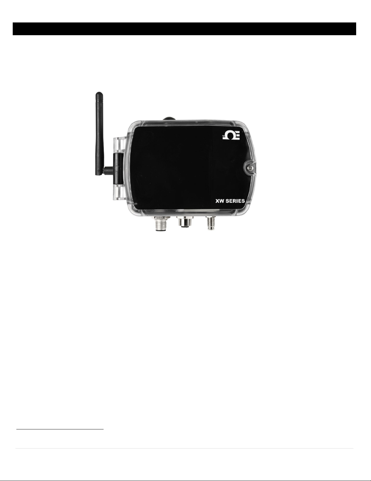
Figure 1
The XW Series Transmitters provide a wireless interface to a range of digital probes, digital I/O, analog process signals, and
precision analog temperature sensors (thermocouple and RTD). The transmitter is IEEE 802.15.4 compliant operating at 2.4
GHz and is designed to transmit up to 1000 m (3280’) outdoors and 100 m (328’) indoors to a ZW-REC coordinator. Its
robust NEMA 4
Core features provide the value of data assurance to retain data even when your power goes out, programmable logic for
triggering I/O, easy configuration through SYNC configuration software, and event logging.
Included with Your XW Transmitter
• 2.4 GHz Antenna
• Mounting Kit
• CR2032 Coin-Cell Battery (Pre-Installed)
• 2x C-Cell Batteries
• Micro USB Cable
Additional Material Needed
• Computer or Laptop with Windows 7 OS and newer
• SYNC by Omega Configuration Software
(Downloadable on the Omega website)
• ZW-REC
• Micro USB Cable for ZW-REC
• Interconnecting probe extension cable (optional)
• AC Adaptor (optional)
Manuals / Software
The latest User’s Manual, Quick Start Guide, and SYNC software are available to download on the Omega website.
1
packaging allows for harsh conditions with the option of DC power or battery power. The integrated Smart
1
Probes may not be NEMA 4 rated. NEMA 4 rating only applies to the XW Transmitter.
6 | Page
Page 7
Hardware Setup
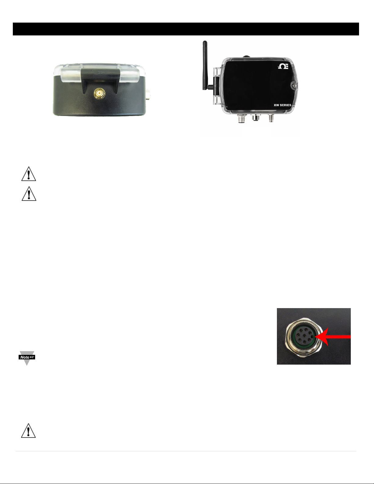
Figure 2
Figure 3
Figure 4
Connecting your Antenna
The XW Transmitter comes with a 2.4 GHz Antenna.
Step 1: Line up the supplied 2.4 GHz antenna with the receiving connector on the XW Transmitter. See Figure 2.
Step 2: Turn the plastic knurl on the antenna in a clockwise direction. See Figure 3 for result.
Important: Hand tighten the antenna onto the XW Transmitter.
Important: Before powering up the XW Transmitter ensure the supplied antenna is properly installed. Running the
XW Transmitter without an antenna, or with an unapproved antenna, may cause damage to the device and/or
cause operation outside of regulatory compliance. Omega Engineering accepts no liability and issues no warranty
for devices operated improperly.
Connecting your Sensors
The XW Transmitter works with a wide variety of sensors. Most sensors come packaged in a probe and each probe is suited
to different applications. Some probes may contain multiple sensors. The XW Transmitter automatically detects connected
sensors on power up and transmits that data to the SYNC configuration software.
For a complete list of sensors compatible with the XW Transmitter, please visit the Omega website.
Probe Installation
8-pin digital probes, including Omega Smart Probes, can be plugged in at this point. Digital I/O or Analog connections should
be made after the XW Transmitter is setup. To install or change a probe, follow these directions:
Step 1: Ensure the XW Transmitter is powered OFF.
Step 2: Take note of the Key Position on the XW Transmitter. See Figure 4. Align this key
with the keyway in the mating connector on the XW Transmitter.
Note: The keyway locations in this manual assume the device is standing in the
position displayed in Figure 4.
Step 3: Turn the metal knurl of the probe in a clockwise direction while leaving the probe body stationary. Ensure that the
probe or interconnecting cable is inserted to the base of the knurl to maintain a NEMA 4 rating on the XW Transmitter.
Step 4: To remove the probe, grasp the plastic knurl only and turn it in a counter clockwise direction. Do NOT rotate the
probe body.
Caution: Do not rotate the body of the probe or the cable. Do not use pliers, vice grips or other tools on probes.
Hand-tighten and hand-loosen only.
7 | Page
Page 8
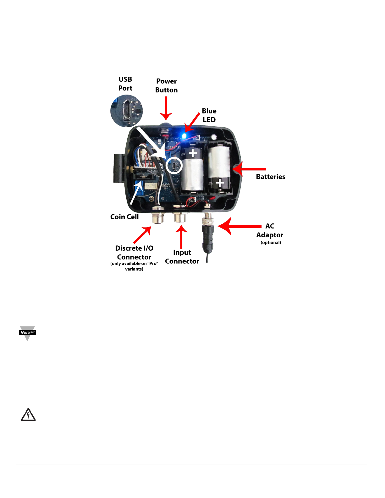
Powering the XW Transmitter
Once the antenna and probe are installed the XW Transmitter may be powered on.
The XW Transmitter can be powered using two alkaline C-Cell batteries, the external M8 connector, or both. The XW
Transmitter automatically switches from the internal batteries to the external power if available. If the external power is
removed, the XW Transmitter switches back to the internal batteries.
Figure 5
Installing Batteries
To install the batteries, follow these steps:
Step 1: Unscrew the lid of the transmitter using a Philips-head screwdriver and open the device.
Note: The battery orientation is marked on the battery holders and is shown in Figure 5.
Step 2: Install the supplied alkaline C-Cell batteries.
Removing Batteries
Step 1: Insert a screwdriver under the battery on the right and gently loosen it. See Figure 5.
Step 2: After removing the battery on the right first, you will have room to remove the remaining battery.
Caution: Use only 1.5V alkaline batteries in the XW Transmitter. Other battery chemistries may damage your device
or lead to reduced battery life.
8 | Page
Page 9
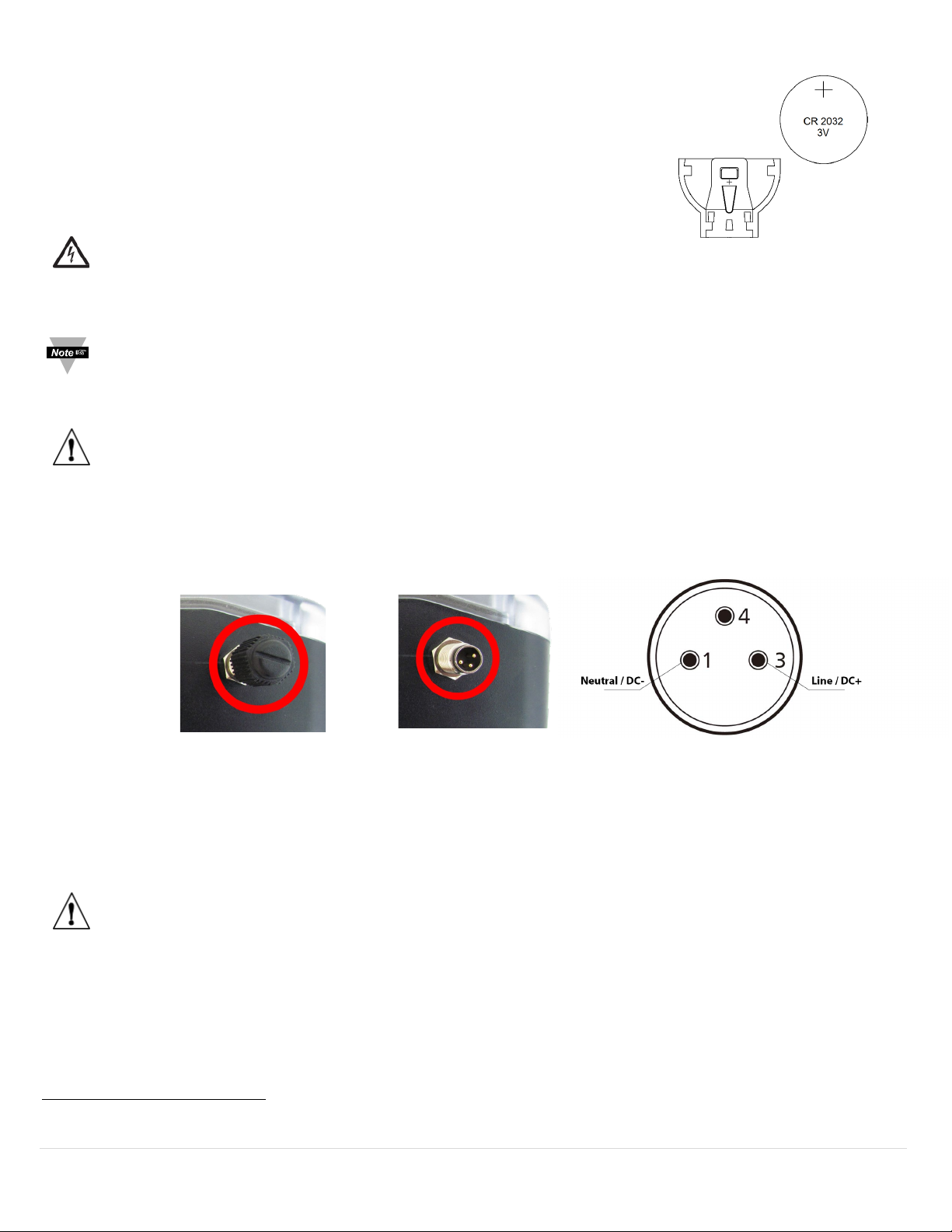
Coin Cell Battery and Replacement
Figure 6
Figure 9
The XW Transmitter comes with a pre-installed CR2032 Lithium Coin Cell Battery. Pull
the tab to begin powering the real time clock. This battery keeps the real time clock
for the XW Transmitter running even when the unit is not powered and has an
expected life of more than 10 years under room temperature conditions. If it needs
to be replaced, follow these directions:
Step 1: Carefully remove the battery from the holder.
Caution: Do not use conductive pliers or other grasping tools that may
short the battery terminals.
Step 2: Take note of the proper orientation as shown in Figure 6.
Note: Based on the orientation of the XW Transmitter in Figure 5, the positive end of the battery should be facing
upward towards the Power Button.
Step 3: Insert the new Coin Cell battery.
Important: The positive battery terminal contact the large terminal and faces the top of the XW Transmitter.
AC Adapter
The XW Transmitter may also be powered using line power through an AC adaptor. The power connector can accept 5V
36V
and 24Vac. An optional Safety Qualified adaptor (UNIV-AC-100/240-5-M8)2 is available to simplify installation. To
dc
install an external power connector, follow these directions.
to
dc
Figure 7 Figure 8
Step 1: Remove the dust cap on the XW Transmitter Power Connector. See Figure 7.
Step 2: Align the sockets in the connector with the pins on the XW Transmitter. See Figure 8.
Step 3: Insert the connector and rotate the metal knurl clockwise while holding the connector body steady.
Caution: Hand tighten only. The connector should be firmly connected to maintain proper operating protection
(NEMA 4 ingress protection). Some exposed threads are normal when the connector is mated.
2
AC Adaptor is not NEMA 4 rated.
9 | Page
Page 10
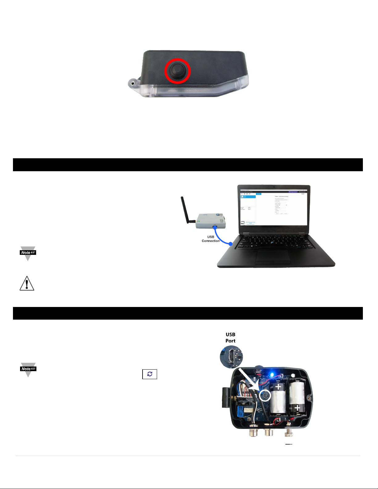
Power Button
Figure 11
Figure 12
The Power Button is located on the top of the XW Transmitter. It allows for powering on and powering off the device.
Figure 10
When you press the power button, the blue LED light will illuminate immediately.
• Turn On: Press and Release the external ON/OFF button to turn on the device. The blue light will illuminate.
• Turn Off: Hold the external ON/OFF button for longer than 7 seconds until you see the blue light is turned off, then
release the button.
• Reset: When the device is ON, push and release the ON/OFF button to reset the device. The blue light will blink.
Configuring your ZW-REC
Ensure your ZW-REC is setup, running, and connected to the computer running SYNC. SYNC will pull the IP Address, Network
Mask, Gateway, and Network ID from your ZW-REC.
Step 1: Turn on your PC and ensure that SYNC
is downloaded, installed, and running.
Step 2: Plug in your ZW-REC to your computer with a
Micro USB cable.
Note: For a complete guide on how to setup your
ZW-REC, refer to the Quick Start Guide available
on the Omega website.
Important: The latest version of the ZW-REC firmware is required. Please ensure you are using the latest version by
visiting the Omega website.
Connecting your XW Transmitter
Step 1: Ensure the XW Transmitter is powered on.
Step 2: Connect the XW Transmitter to your computer
via Micro USB cable. See Figure 12.
Note: SYNC will auto-detect your XW Transmitter. If the
auto-detect feature fails, please click in SYNC to
search for connected devices, or refer to the section titled
Connecting to SYNC – Manual.
10 | Page
Page 11
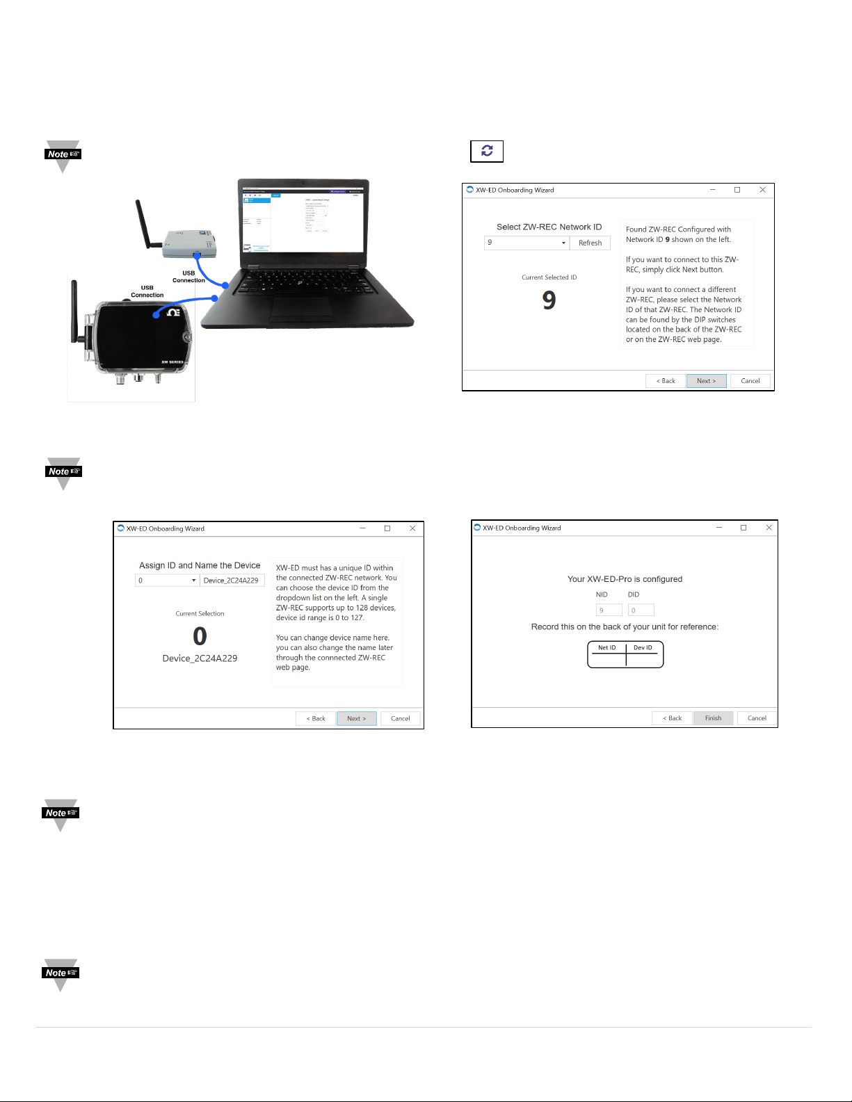
Connecting to SYNC – Auto Detect
Figure 14
Figure 15
Figure 16
Figure 13
Before you begin, ensure your XW Transmitter and ZW-REC are connected to the computer running SYNC.
Step 1: Once the XW Transmitter is connected via Micro USB cable and is auto-detected, click Next.
Note: If SYNC does not auto-detect the XW Transmitter, click to search for connected devices.
Step 2: SYNC will detect the Network ID of the previously connected ZW-REC (Default is 0). Click Next.
Note: The Network ID is a unique identification number that allows a device to be identified within a network. In
the case of having multiple ZW-RECs, you will have to choose which ZW-REC you would like to connect to by
selecting the Network ID of your preferred ZW-REC.
Step 3: Assign a unique Device ID to your XW Transmitter.
Note: The Device ID is a specific number (between 0 and 127) assigned to your XW-ED that will identify this device
to the receiver it was assigned to.
Step 4: Assign a device name to your XW Transmitter.
Step 5: Review your selections and click Finish.
The blue LED will begin to flash quickly and turn off to display that a connection was successfully established. The LED will
flash again each time a new reading is transmitted.
Note: If you have successfully connected your XW Transmitter to SYNC, skip ahead to section Viewing Your
Transmitter.
11 | Page
Page 12
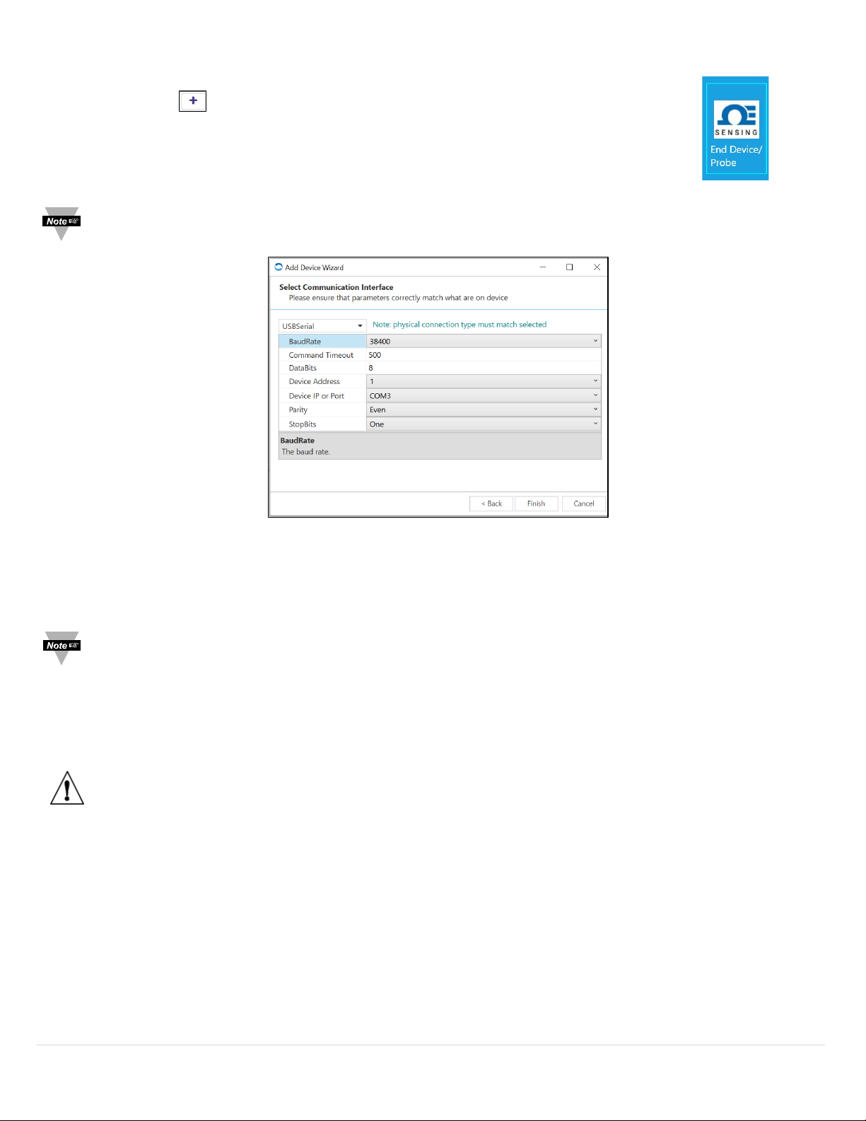
Connecting to SYNC - Manual
Figure 18
Figure 17
Step 1: Power on your XW Transmitter and connect the device to your computer via USB cable.
Step 2: Click on the icon located on the top left of the SYNC interface.
Step 3: Proceed through the Add Device Wizard.
Step 4: Click End Device / Probe. See Figure 17.
Note: The connection type and parameters must be accurate for a proper connection to be established. Failure to
accurately setup communication parameters may result in communication errors.
Communication Interface
• Connection Type: Select the type of connection you have between your XW Transmitter and your computer. The XW
Transmitter connects to your computer via USBSerial as displayed in Figure 18.
Note: The connection type must be accurate for a proper connection to be established.
• Command Timeout: The maximum time (in milliseconds) for a command to be completed before the command is
aborted. The default command timeout is 500 milliseconds. It is recommended that this section be left alone to avoid
communication errors.
• Device IP or Port: The COM port number that your device is connected to on your computer.
Important: The following parameters should NOT be changed.
• Device Address: If your device is attached to a Bus Network such as Modbus or RS485, the device address is the Bus
Network ID it will be assigned to. The default address is 1. This should only be changed when seeking a specific Bus
Network.
• BaudRate: Controls bits per second.
• DataBits: The number of ‘bits’ in each character sent.
• Parity: A means of checking correctness of character by adding an extra ‘bit’ to the character and setting the value
based on all the other bits in the character.
• StopBits: The number of ‘bits’ used to indicate the end of the character.
12 | Page
Page 13
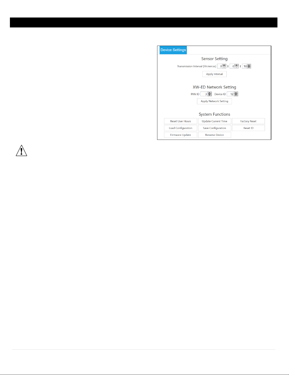
Customize Device Settings
Figure 19
To customize the device settings of your transmitter, click the Device Settings Configuration Tab.
Sensor Setting
Transmission Interval must be set by the ZW-REC and controls the
frequency that readings are sent from the transmitter to the
receiver.
XW Transmitter Network Setting
This section allows you to change the PAN ID/Network ID and
the Device ID of the XW Transmitter separate from the Add
Device Wizard.
System Functions
• Reset User Hours: Resets the operation hours of the XW
Transmitter as displayed in SYNC.
• Update Current Time: Changes the XW Transmitter’s internal
clock to sync with the clock of the computer it is connected to.
Important: Click Update Current Time when setting up the
XW Transmitter for the first time to ensure accurate date
and time are reflected in the data logging.
• Factory Reset: Resets the XW Transmitter to its factory settings.
• Load Configuration: Allows the user to load a configuration file (.json) from the computer the XW Transmitter is
connected to.
• Save Configuration: Saves the current configuration set for the XW Transmitter into a .hex file.
• Reset ID: Allows the user to reset the Network ID and the Device ID of the XW Transmitter through the XW Transmitter
Onboarding Wizard.
• Firmware Update: Allows the user to load a firmware update file (.hex) from the computer the XW Transmitter is
connected to.
• Rename Device: Allows the user to change the name of the XW Transmitter.
13 | Page
Page 14
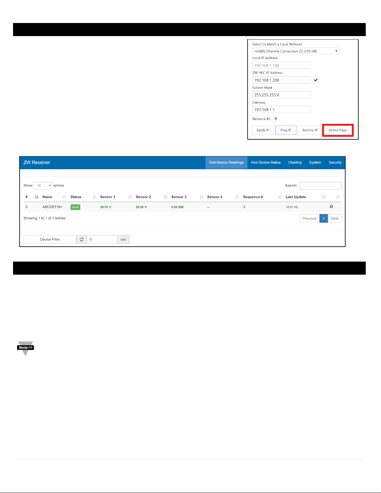
Viewing Data on the ZW-REC Page
Figure 20
Figure 21
Once your XW Transmitter has been successfully connected to your ZW-REC,
you will be able to view the transmitter on the ZW-REC webpage.
You may navigate to the ZW-REC webpage through SYNC by clicking the
Home Page button as seen in Figure 20.
Alternatively, you may navigate to the ZW-REC webpage by typing the
ZW-REC IP Address into your web browser.
8-pin digital probes, including Omega Smart Probes that have already been
connected, will transmit readings to the ZW-REC webpage. See Figure 21.
To configure Digital I/O, Analog connections, or view wiring diagrams of the XW
Transmitters, proceed through this manual to find the relevant connection type.
XW-ED Wiring
The XW-ED is a versatile transmitter that can accept a wide variety of digital probes, function as a rate/timer/totalizer, or as
an mA/mV meter.
Digital Probes
The XW-ED is configured to use digital probes by default. Simply attach your probe to the 8-Pin M12 connector and the
XW-ED will automatically connect it. SYNC can then be used to setup smart probe specific options. Please refer to your
smart probe User’s Manual for more details.
Note: Probes should be connected to the XW-ED before starting SYNC. If you have a Probe with Digital I/O
connected to an XW-ED-PRO, the Probe Digital I/O will show up before the XW-ED-PRO Digital I/O in SYNC and on
the ZW-REC Web interface.
14 | Page
Page 15
Digital Input (Timer/Totalizer)
Selection
Measurement
Description
DIN
Digital Input
3-bit Binary Digital Input
RATE
Frequency
Measure the Frequency of Rising or Falling Edges
WIDTH
Pulse Width
Measure the Active time of a signal
DUTY
Duty Cycle
Measure the % of Active time of a signal
DELAY
Delay Timer
Measure the time Between the Rising or Falling Edges of 2 Signals
CNT
Up Counter / Totalizer
Counter with Enable and Reset
U/D_CNT
Up/Down Counter / Totalizer
Counter with Direction and Reset
Frequency, Pulse
Width, Duty Cycle
Up / Down
Counter
Pin 2
Enable
Pulse B
Direction
Input 3
Pin 3
Pulse
Pulse A
Pulse
Input 1
Pin 4
Reset
Reset
Reset
Input 2
Pin 5
Shield
Pin 6
NC
Pin 7
GND
Pin 8
3.3V Output
Rear view of Filed Connector Shown
Figure 22
Figure 23
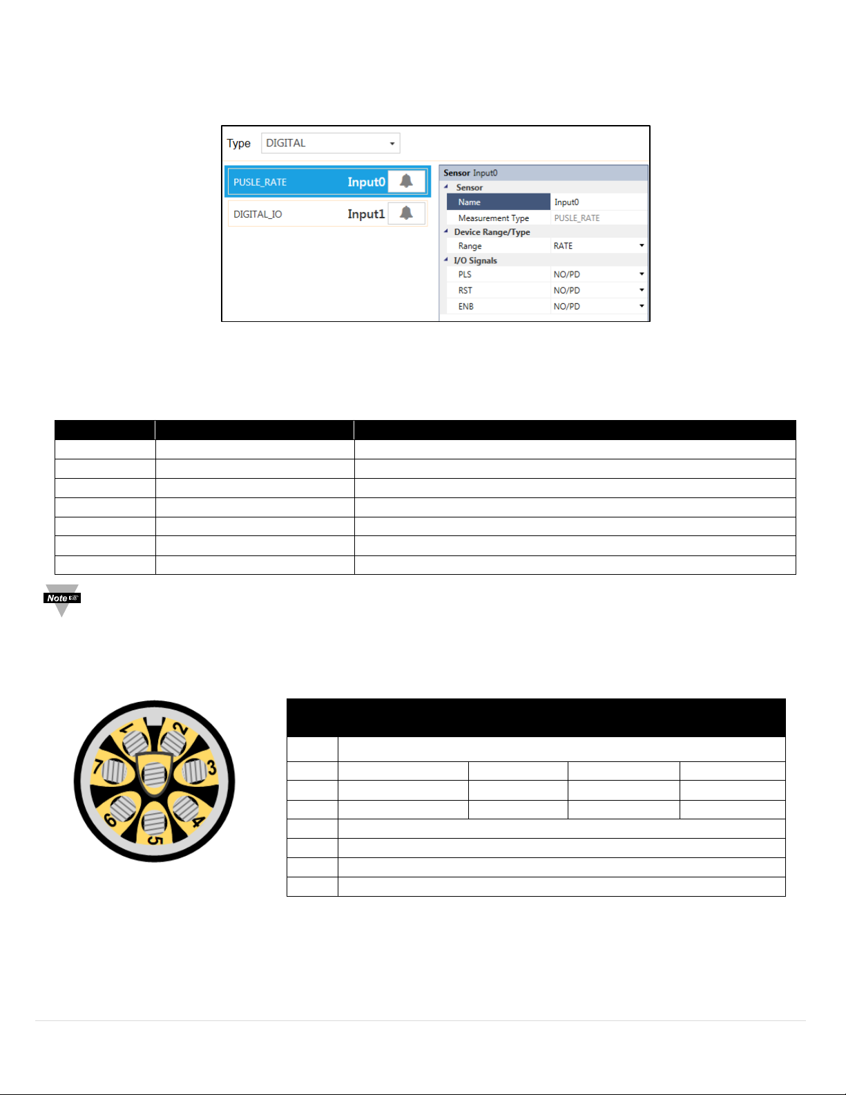
The XW-ED also functions as a flexible Digital Input with Timer and Totalizer functions. To use these features, change
the input type to Digital on SYNC.
Select the type of digital input is selected in the Device Range/Type pull-down in the side bar. The following types are
available:
Note: Descriptions of the Digital Range/Types are available in Appendix A of this User’s Manual.
Each digital measurement type has three inputs. The functions of each of these inputs change with the selected type
and can be seen in SYNC and are described in the chart below:
Pin 1 NC
Delay
Digital Input
15 | Page
Page 16
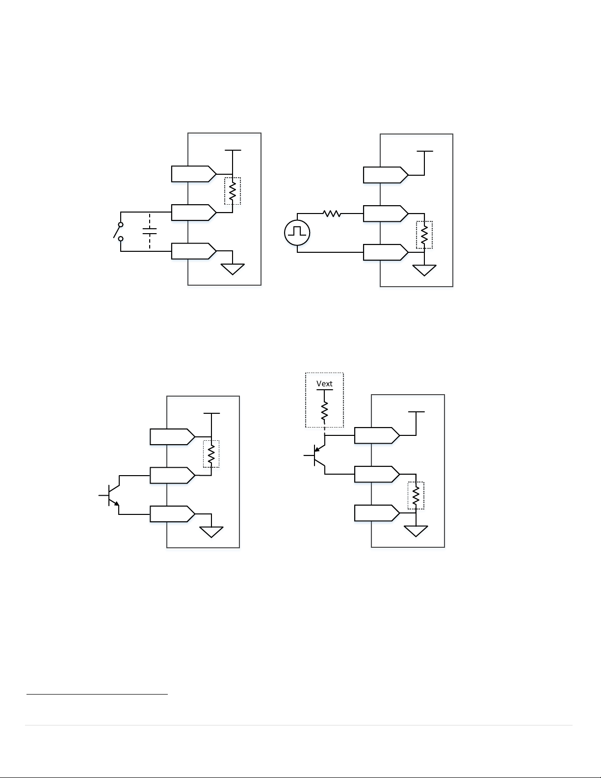
Each of the three input pins can be independently set to either have an internal 1.5k Pull Up or Pull Down and can be set to
Relay or Switch
For Active High Select Normally Closed
For Active Low Select Normally Open
P.2/3/4
P.7
P.8
3.3V
Pu ll Up
Debounce
Capacitor
Suggested
P.2/3/4
P.7
P.8
3.3V
Pu ll Dow n
Pu lse / TTL Input
Do not Exceed
3.3V at Input Pin
For Active High Select Normally Open
For Active Low Select Normally Closed
NPN or N-MOS Tran sistor
Input
For Active High Select Normally Closed
For Active Low Select Normally Open
P.2/3/4
P.7
P.8
3.3V
Pu ll Up
P.2/3/4
P.7
P.8
3.3V
Pu ll Down
PNP or P-MOS Transistor
Input
For Active High Select Normally Open
For Active Low Select Normally Closed
Vext
Optional
Ex te rn al
Po wer
Do not
Exceed
3.3V at
Input Pin
Figure 24
Figure 26
be either Active High or Active Low. Internally supplied 3.3 power is available for biasing
3
.
Some typical Circuits are show below:
Figure 25
Figure 27
3
150 mA max. Using internal power or internal pullups will reduce battery life.
16 | Page
Page 17
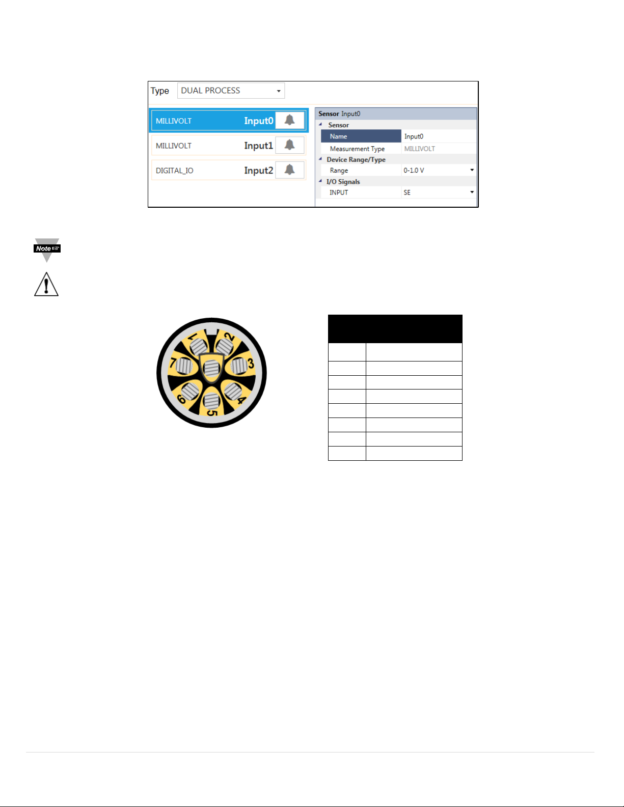
Process Input
Frequency, Pulse
Width, Duty Cycle
Pin 2
Input 1
Pin 3
Input 0
Pin 4
NC
Pin 5
Shield
Pin 6
NC
Pin 7
GND
Pin 8
3.3V Output
Figure 28
Figure 29
Rear view of Filed Connector Shown
The XW-ED can also accept up to two 0-24 mA or 0-1.0 V
process inputs. Select either Single Process or Dual Process
DC
from the Type selection and then choose the Device Range/Type option in the side bar.
Note: When using Dual Process, the Device Range/Type section is only available for Input 0. Input 1 is always the
same type as Input 0.
Warning: Be sure to setup the unit before plugging in Process inputs.
Pin 1 NC
17 | Page
Page 18
XW-EDA Wiring
Thermocouple
Pin 1
TC 2 Negative
Pin 2
TC 1 Positive
Pin 3
TC 1 Negative
Pin 4
TC 2 Positive
Figure 30
Figure 31
Rear view of Filed Connector Shown
The XW-EDA model supports thermocouples, RTD’s, and precision process inputs. The sensor inputs signals are provided on
an M12, 4-pin female connector and are logically broken into 2 unique channels.
Thermocouple
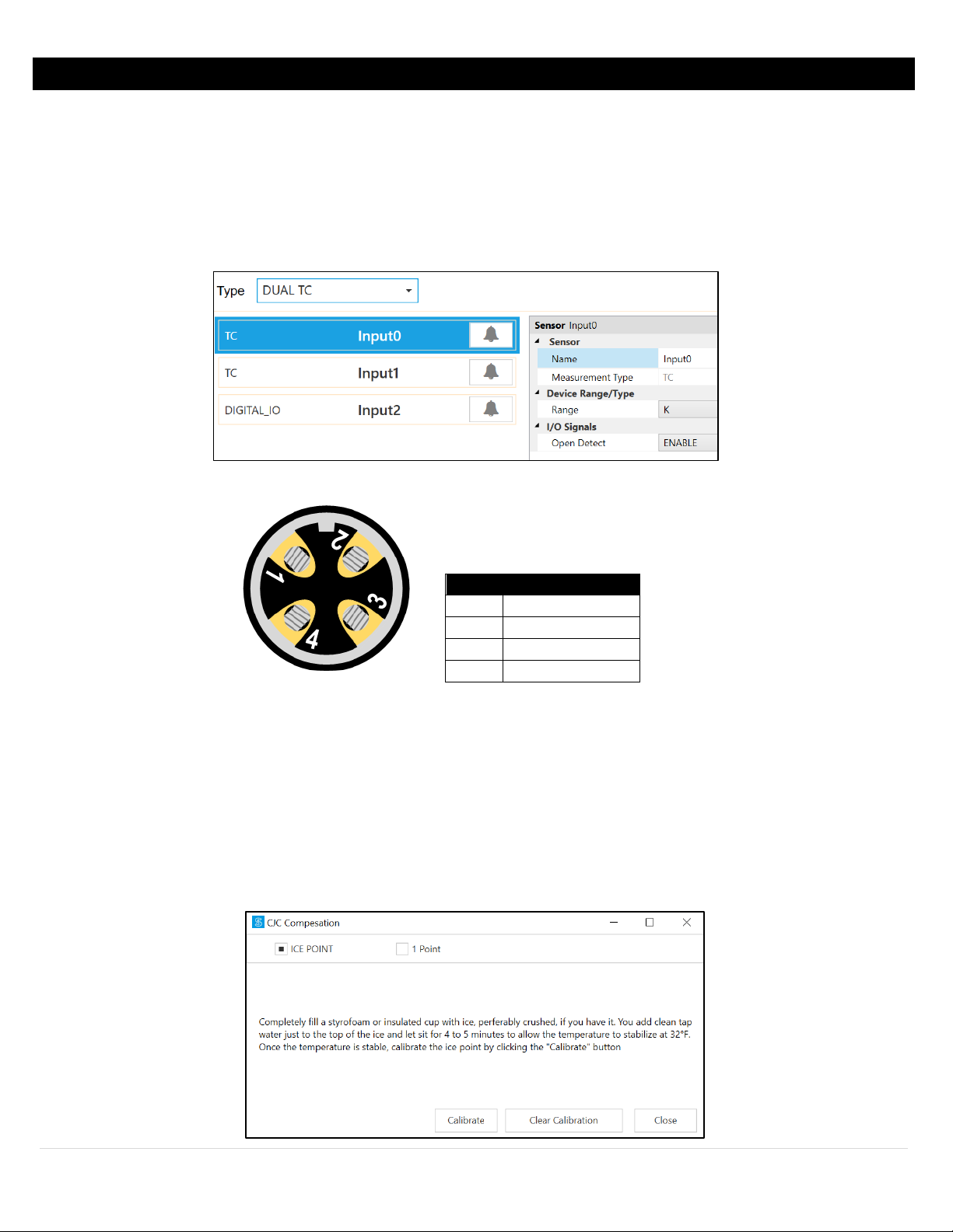
The Thermocouple Input interface provides interfaces to type J, K, T, E, N, R, S, B and C thermocouples with the capability of
enabling or disabling the open detect feature.
To use these features, change the input type to Single TC or Dual TC using SYNC.
Cold Junction Compensation
The thermocouple input interface offers cold junction compensation calibration. To achieve proper Ice Point calibration,
you must be able to immerse your thermocouple into an environment that is stabilized at 0°C (32°F).
To use this calibration feature, change the input type to Single TC or Dual TC using SYNC (see Figure 30) and click
Calibration beneath the input interface. Once the Thermocouple is stable in the 0°C environment, click calibrate.
18 | Page
Page 19
Process
Voltage
Current
Pin 1
Input 1
Input 1
Pin 2
Input 2
Input 2
Pin 3
Ground 2
Ground 2
Pin 4
Ground 1
Ground 1
Figure 32
Figure 34
Figure 33
Rear view of Filed Connector Shown
Input
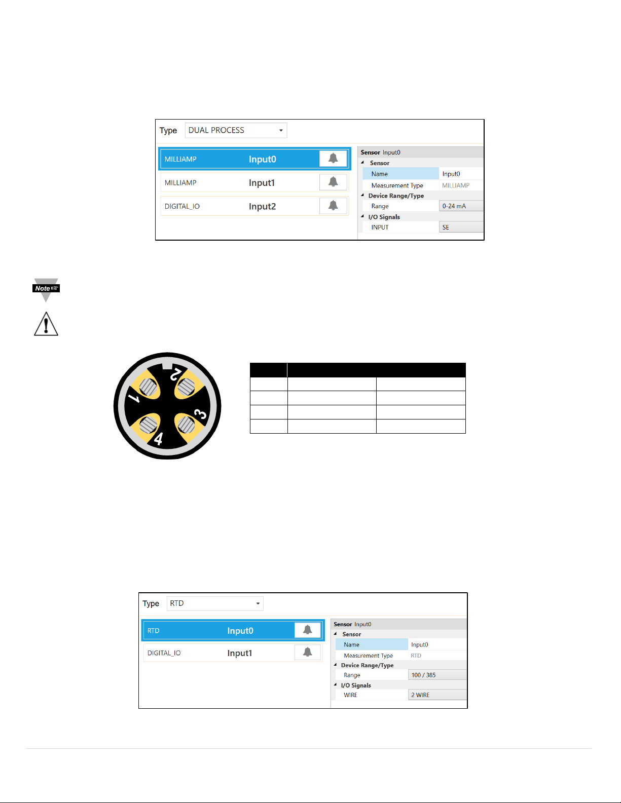
The Process Input (Single & Dual) accept up to two 0-24 mA, 0-0.1 V
, 0-1.0 VDC, or 0-10 VDC process inputs. To use
DC
these features, change the Input Type selection to Single Process or Dual Process and then choose the Device
Range/Type option in the side bar.
Note: When using Dual Process, the Device Range/Type section is only available for Input 0. Input 1 is always the
same type as Input 0.
Warning: Be sure to setup the unit before plugging in Process inputs.
RTD
Input
The RTD Input interface provides interfaces to type 100, 500, and 1000 ohm 385 Curve, 100 ohm 392 Curve, and 100
ohm 3916 Curve RTD devices in 2, 3 and 4 wire configurations. A single RTD connection is supported.
To use these features, change the input type to RTD using SYNC.
19 | Page
Page 20
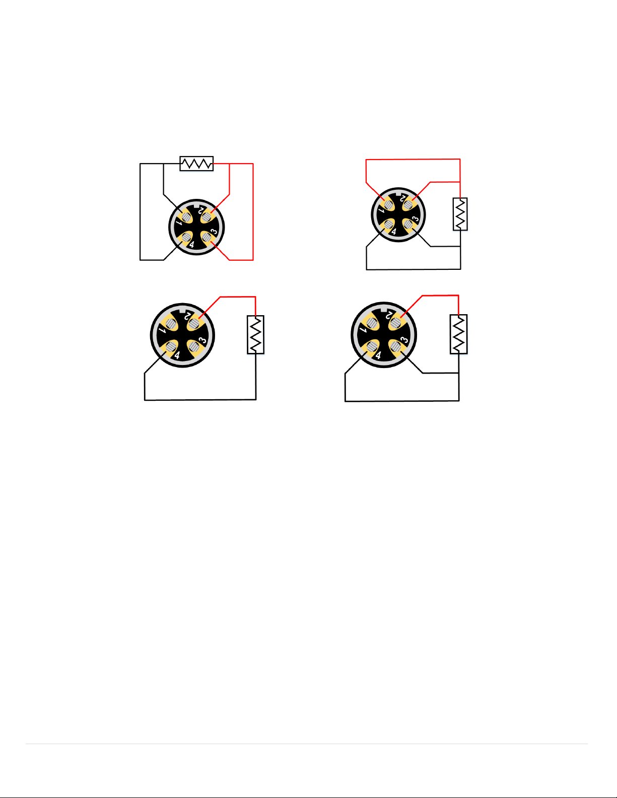
Wiring diagrams are displayed below.
• 2 Wire RTD Connections: Most useful with high-resistance sensors or in applications where a great deal of
accuracy is not required.
• 3 Wire RTD Connections: This connection is best suited for devices like strain gauges and is most often seen in
industrial process and monitoring applications.
• 4 Wire RTD Connections: A 4 Wire RTD configuration is primarily used in laboratories and other settings where
great accuracy is necessary.
RTD 4 Wire Option 1 RTD 4 Wire Option 2
RTD Wire 2 RTD Wire 3
20 | Page
Page 21
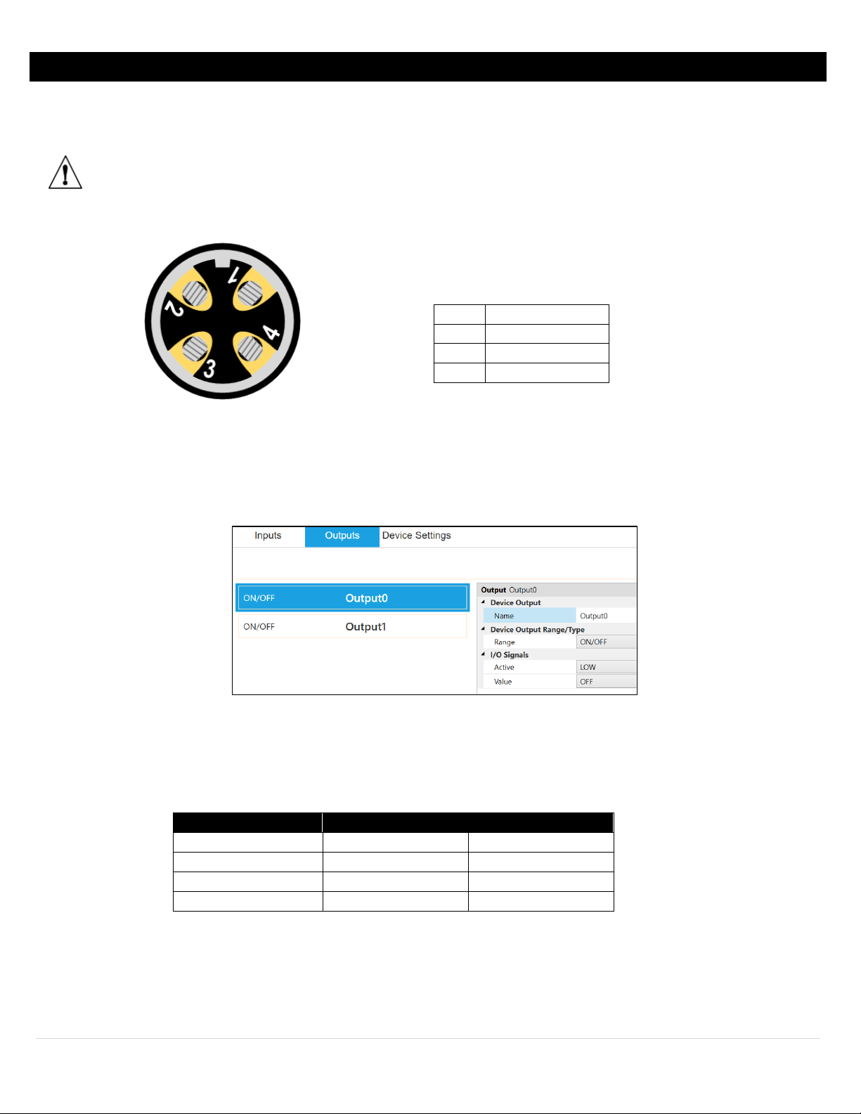
XW-ED-PRO and XW-EDA-PRO Wiring
Input 1
Input 0
Reading
Inactive
Inactive
0
Inactive
Active
1
Active
Inactive
2
Active
Active
3
Pin 1
Input / Output 0
Pin 2
Input / Output 1
Pin 3
Ground
Pin 4
Ground
Rear view of Filed Connector Shown
Figure 35
Figure 36
The XW-ED and XW-EDA Pro versions support 2 Discrete Open Drain Digital Inputs / Outputs on the 4 Pin M12 Male
connectors. To connect an input or output a standard M12 4pin cable can be used. Omega also offers an optional field
installable M12 connector.
Important: For the XW-ED-PRO, Digital I/O is only available when the input is set to Process or Digital or if an
Omega Smart Probe is used. Older zSeries probes will automatically disable the Digital I/O.
Pro Discrete Input / Output Connector
Input Settings
To use a pin as an input make sure it is set to Active Low (default) in the Output Tab in SYNC. The Input can then be set as
Active High or Low in the Input Tab.
Each pin has an internal pull-up, but in order to save power, the internal pull-up is only active when the unit takes a
reading. The state of both pins is always shown on the ZW-REC as the last input. Refer to the following table to decode
the input state.
21 | Page
Page 22
Output Settings
Option
Value
Description
LOW
When the output is inactive, it is in a high impedance state.
HIGH
When the output is active, it is in a high impedance state.
OFF
Set output inactive.
ON
Set output active.
Option
Value
Description
100 Hz
Signal has constant 100 Hz frequency with 0-100% Duty Cycle.
10 Hz
Signal has constant 10 Hz frequency with 0-100% Duty Cycle.
1 Hz
Signal has constant 1 Hz frequency with 0-100% Duty Cycle.
0.1 Hz
Signal has constant 0.1 Hz frequency with 0-100% Duty Cycle.
Signal
Type
Active LOW
When the output is inactive, it is in a high impedance state.
Active HIGH
When the output is active, it is in a high impedance state.
Level
0-100%
Sets the duty cycle from 0-100%.
Figure 37
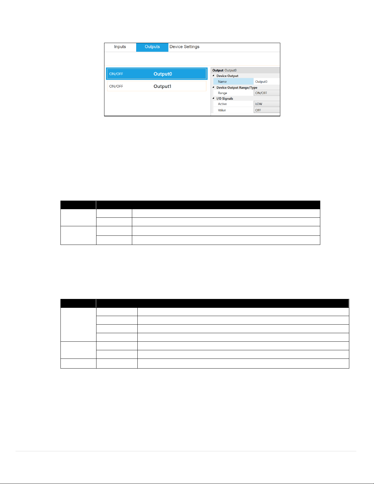
To use a pin as an output, set up the Output Options and assign the output to an Alarm using SYNC.
Output options are set in the Output Tab of Omega Sync. Each output can be configured as either Active High or Active
Low. When configured as Active High the output conducts normally and becomes high impedance when activated. When
configured as Active Low the Open Drain output is high impedance normally and will conduct when activated. It is
recommended to change the input type to match the output type so that the output state will be correctly represented in
logs.
• ON / OFF: Controls on/off functions. I/O signals can be changed between Active High, Active Low, and inactive
Active
Value
• PWM: Pulse Width Modulation controls the amount of power given to a device by cycling the on/off phases of a
digital signal. PWM consists of a duty cycle and frequency. The Duty Cycle measures the amount of time a signal is
in the ON state as a percentage. The frequency controls how fast the PWM cycle is repeated. Users can select
between the following settings:
Rate
22 | Page
Page 23
Alarms
Figure 38
Figure 39
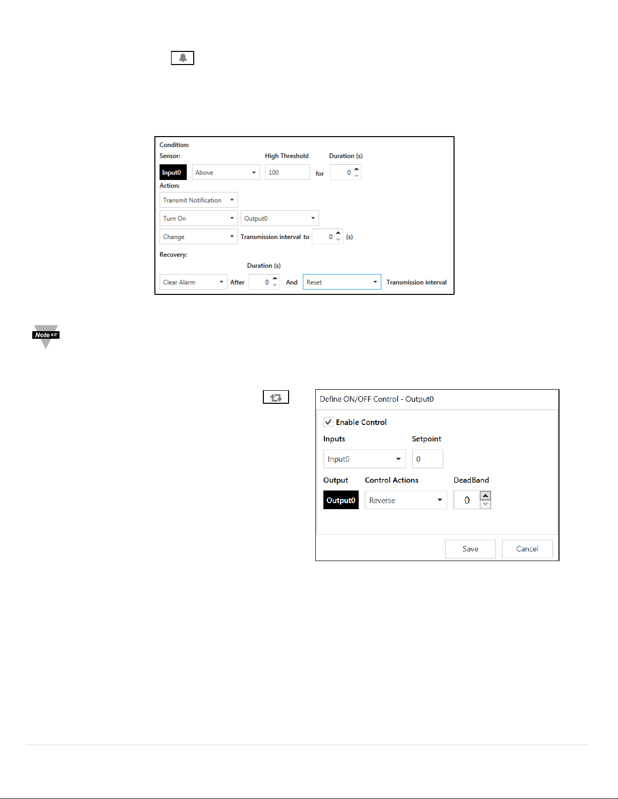
Alarms are set by clicking the icon on the desired input signal found in the Input Configuration Tab. Setup the
threshold and alarm type in the Condition section and then select which output to turn on in the Action section. The
alarm can be set to be latching or non-latching in the Recovery section. If the alarm is set to be latching, press the reset
button on the XW Transmitter to clear the Alarm.
The alarm state is now viewable on the ZW-REC webpage by monitoring the DIN input.
Note: When alarms are enabled readings are taken once per second. This greatly reduces battery life, therefore an
AC Adaptor is recommended.
ON/OFF Control
To configure ON/OFF Control on a device, navigate to the
Output configuration tab in SYNC and click on the icon
located to the right of the available outputs. Clicking the
icon will open the Define ON/OFF Control dialog box as
seen in Figure 36. Choose the input with the active alarm
that you would like to control and set your preferred
parameters.
The Setpoint establishes the target process value and the
Deadband establishes the range from the Setpoint that the
process value can accept before the output is activated.
When Reverse control is selected, the output is on when the
process value is below the Setpoint. When Direct control is
selected, the output is on when the process value is above
the Setpoint.
Once the ON/OFF Control parameters have been set, click
Save to finalize the settings.
More functions are constantly being developed for the XW Transmitter and other smart devices. Check the latest SYNC
version for the newest updates.
23 | Page
Page 24
Appendix A: Digital Input Diagrams
I/O Signal
Description
INP_1, INP_2, INP_3
Inputs may be treated as simple ON/OFF switch inputs.
I/O Signal
Description
Detects the positive or negative pulse edge depending on the signal type and
modifier chosen.
RST
Resets the value to 0 when active.
Enables measurement when active.
Holds the last measurement when inactive.
Serves as the second signal line and is measured alongside CLK_A to determine
the Pulse Delay.
The following information provides descriptions and diagrams of the available I/O capabilities of the XW-ED and XW-EDPRO.
Digital Input
• DIN: The Digital I/O functions present a bit mapped image of the signals present on the corresponding
channel signal lines. The Digital I/O signal lines may be read as inputs to initiate control functions and to
activate alarms.
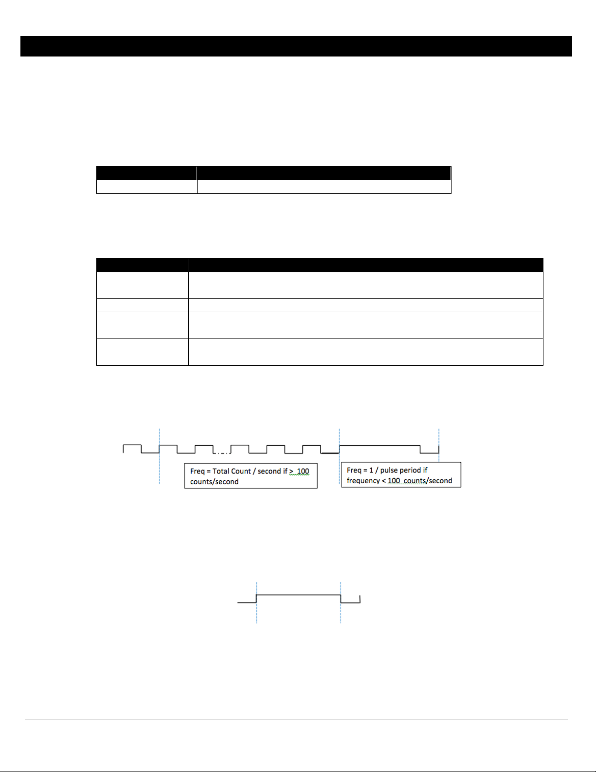
Pulse Measurements
Pulse measurements include Pulse Rate (Frequency), Pulse Width, Duty Cycle, and Pulse Delay. Pulse
measurements contain the following customizable I/O signals:
CLK_A
ENB
CLK_B (Delay only)
• RATE: The Rate (Pulse Rate Frequency) function measures the number of OFF to ON transitions in 1 second.
Rate counters may be used to measure the frequency of external signals and are often used to measure
speed/flow by coupling a magnetic transducer to a toothed wheel or impeller-based flow transducers.
• WIDTH: The Pulse Width function measures the time (in seconds) that the CLK (clock) signal is in the ON
state. Width timers may be used to measure the frequency of external signals and are often used to
measure speed by coupling a magnetic transducer to a toothed wheel or impeller-based flow rate
transducers.
24 | Page
Page 25
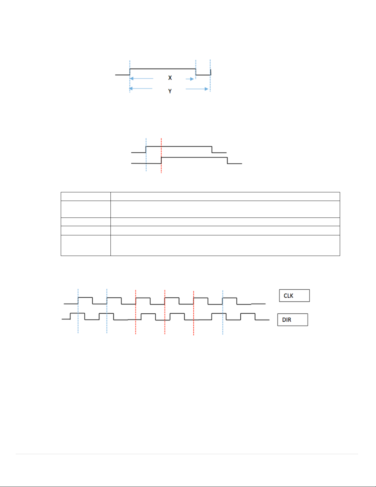
• DUTY: The Duty Cycle function measures the percentage of time the CLK (clock) is high as a percentage of
I/O Signal
Description
Measures the positive or negative pulse depending on the signal type and
modifier chosen.
RST
Resets the counter to 0 depending on the signal type and modifier chosen.
ENB
Sensor starts measuring depending on the signal type and modifier chosen.
Determines what aspect of the pulse is counter (Up or Down) depending on the
the total time of the signal. The Duty Cycle function may be used to measure the percent ‘power’ or servo
control position being controlled by a PWM (pulse width modulation signal.
• DELAY: The Pulse Delay function measures the delay in time between Signal Line 1 (CLK 1) and Signal Line 2
(CLK 2) turning ‘ON.’ The Pulse Delay function may be used to measure the time between two signals
turning on or the phase angle of AC signals with suitable signal conditioning.
Counter Measurements
Duty Cycle = x/y%
CLK_A
DIR (Up/Down
only)
• CNT: The Counter function measures the number of OFF to ON transitions on the CLK signal. The counter
function may be used to measure the number of occurrences of an external event.
• U/D_CNT: The Up/Down Counter function measures the number of OFF to ON transitions on the CLK signal.
The Up/Down Counter function may be used to measure the number of occurrences of an external event or
the positioning of external devices based on a suitable transducer.
signal type and modifier chosen.
25 | Page
Page 26
Appendix B: Specifications
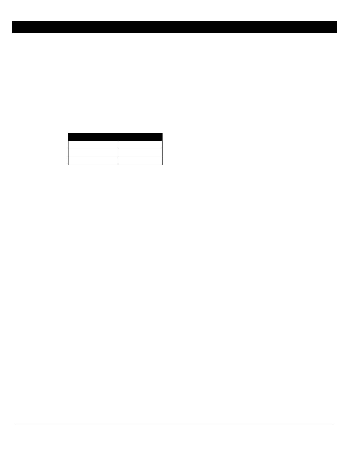
Sleep Time
Battery Life**
10 Seconds
1.5 Years
60 Seconds
3.5 Years
10 minutes
4.5 Years
Wireless Communication
Standard: IEEE 802.15.4, DSSS
Frequency: 2.4 GHz (2400 to 2483.5 MHz), 16 channels
Network Topology: Star topology
Transmit Power: 9.5 dBm
Receiver Sensitivity: -96 dBm
Range: Up to 1000 m* (3280’) outdoor and 100m* (328’) indoor
*without obstruction
Power
Input Voltage: 5 to 36 V
Input Power: 0.8 W maximum
Alkaline Battery: Two C-Cell 1.5 Vdc (included)
Lifetime: With Alarms or Control Active: Up to 3 months
**At 25°C with good reception
Lithium Back-Up*** Battery: CR2032 (included)
***RTC back-up only
Safety Qualified AC Power Adaptor (optional):
Nominal Output: 5 V
Input: 100 to 240 V
Operating Temperature: 0 to 40°C (32 to 104°F)
Environmental
Operating Conditions:
Base Unit: -20 to 70°C (-4 to 158°F), 90% RH non-condensing
CR2032 Battery: -20 to 60°C (-4 to 140°F), 90% RH
Alkaline Battery: -18 to 55°C (-0.4 to 131°F), 90% RH non-condensing
Packaging
Enclosure Material: Polycarbonate
Enclosure Protection: NEMA 4 (IP65)
Enclosure Dimensions: 135.9 L x 82 W x 39 mm D (5.35 x 3.23 x 1.56”)
General
Agency Approvals: ECCN, EAR99, EMC 2014/30/EU, LVD 2014/35/EU, RED 2014/53/EU
Software: Compatible with OMEGA Sync and OEG
Compatible Probes: Smart Probes, zSeries****
****when using zSeries Probes with the Pro version, the Discrete I/O will be disabled
, 24 VAC ±10%
DC
@ 0.6 A
DC
, 50/60 Hz
DC
26 | Page
Page 27
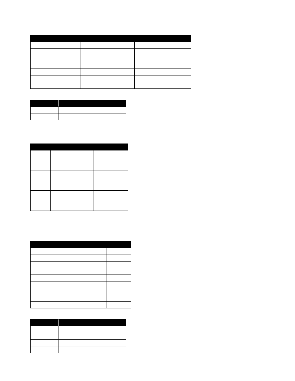
XW-ED and XW-ED-PRO Inputs
Type
Range
Accuracy
Frequency
0.01Hz to 100Hz
±0.5%
Frequency
100Hz to 1000Hz
±1Hz averaged over 1s
Counter
0 to +8388608
±1 count max
Up / Down Counter
-8388608 to +8388608
±1 count max
Pulse Width (Tpw)
0.2ms min
±50uS ±1%
Pulse Delay (Tpp)
0.2ms min
±50uS ±1%
Duty Cycle
1% to 99%
±50uS *F
Type
Range
Accuracy
Current
0-24mA
±0.1mA
Voltage
0-1V
±5.0mV
Type
Range
Accuracy*
J
-210°C to 1200°C
0.4°C
K
-160°C to 1372°C
0.4°C
T
-190°C to 400°C
0.4°C
E
-220°C to 1000°C
0.4°C
N
-100°C to 1300°C
0.4°C
R
40°C to 1788°C
0.5°C
S
100°C to 1768°C
0.5°C
B
640°C to 1820°C
0.5°C
C
0°C to 2320°C
0.4°C
Type
Range
Accuracy
385, 4 Wire
-200°C to 850°C
0.3°C
385, 3 Wire
-200°C to 850°C
0.3°C
385, 2 Wire
-200°C to 850°C
0.6°C
392, 4 Wire
-200°C to 660°C
0.3°C
392, 3 Wire
-200°C to 660°C
0.3°C
392, 2 Wire
-200°C to 660°C
0.6°C
3916, 4 Wire
-200°C to 660°C
0.3°C
3916, 3 Wire
-200°C to 660°C
0.3°C
3916, 2 Wire
-200°C to 660°C
0.6°C
Type
Range
Accuracy
Current
0-24mA
±10uA
Voltage
0-10VDC
±5.0mV
Voltage
0-1VDC
±0.5mV
Voltage
0-0.1VDC
±0.05mV
Digital Inputs
Process Inputs
XW-EDA and XW-EDA-PRO Inputs
Thermocouple
*At 25°C CJC
Accuracy: ±0.05°C per C
RTD
Process Inputs
27 | Page
Page 28

Appendix C: Troubleshooting and Help
Symptom: My XW-ED/XW-ED-PRO shows “OPEN” or “NaN” on the ZW-REC webpage.
Solutions:
• Check that the probe is connected properly, and the input connector is wired correctly.
• If using thermocouple short pins 2 and 3 together for Channel 0 and Pins 1 and 4 together for channel 1. If
the unit displays room temperature check your thermocouple for breaks.
Symptom: All my transmitters are missing after power cycling the ZW-REC.
Solution: On the ZW-REC System page make sure the “Enable Energy Scan at Startup” box is not checked. If
transmitters are set for long sleep times they will show up after they transmit next.
Symptom: Blue Light blinks on and off rapidly. XW-ED does not show up on the ZW-REC webpage.
Solution: Use Omega Sync to check that NID is the same as the ZW-REC and that the DID is not used by another device.
Symptom: Blue Light is on solid and reset button is not working.
Solution: Remove power, Batteries and Coin Cell from unit. Wait 5 seconds before applying power again.
Symptom: My transmitters sometimes appear as “Lost” on the ZW-REC webpage.
Solutions:
• Try to reposition your receiver or transmitter away from other wireless devices, microwaves, motors, and
other potential sources of interference. Make sure the antennas for all devices are pointed upwards.
• Try using a different RF channel that does not overlap with existing WiFi channels being used. All transmitters
must be power cycled after changing the RF Channel. (See ZW-REC User’s Manual).
28 | Page
Page 29
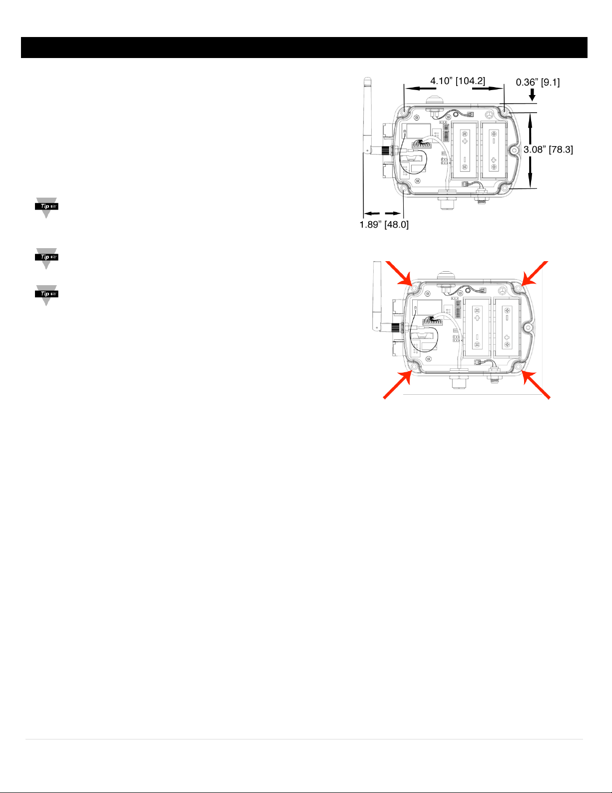
Appendix D: Mounting your XW Transmitter
Figure 40
Figure 41
Step 1: Position the unit where you would like to mount it.
Mark the location of the top center of the unit.
Step 2: Unscrew the lid screw using a Philips head screwdriver to
open the XW Transmitter and access the mounting points.
Step 3: Refer to Figure 24 to mark and drill four pilot holes
as indicated. Use the included drywall anchors if needed.
Step 4: Use the included screws to secure the XW Transmitter.
Tip: When mounting the unit, be sure to leave room on the
top to access the power button and on the bottom and
side for the probe and antenna.
Tip: Mount the unit away from any large metal obstructions
such as posts, catwalks, or large machinery.
Tip: For the best wireless range do not collocate the XW
Transmitter with other 2.4Ghz wireless equipment such as
Bluetooth, Zigbee, or any other wireless router or access
points not belonging to the same wireless network.
29 | Page
Page 30

Appendix E: Safety and Regulatory Compliance
Safety:
EN 61010-1 3rd Edition
EMC:
EN 61326-1:2013
Radio:
EN 300 328 V1.8.1: 2012-04
CE:
The product herewith complies with the essential requirements and other relevant provisions of the Radio Equipment Directive
2014/53/EU, the EMC Directive 2014/30/EU, and the Low Voltage Directive 2014/35/EU, and carries the CE-marking
accordingly.
The following CE Mark is affixed to this equipment.
The CE declaration is available at the website listed on the cover page of this manual.
FCC / IC:
Part 15C, Class DTS Intentional radiator
Contains TX FCC ID: TYOJN5168M5
Contains Industry Canada ID IC: 7438A-CYO5168M5
FCC Radiation Exposure Statement:
This portable equipment with its antenna complies with FCC’s RF radiation exposure limits set forth for an uncontrolled
environment. To maintain compliance, follow the instructions below:
1. This transmitter must not be co-located or operating in conjunction with any other antenna or transmitter.
2. Avoid direct contact to the antenna or keep it to a minimum while using this equipment.
30 | Page
Page 31

WARRANTY/DISCLAIMER
OMEGA ENGINEERING, INC. warrants this unit to be free of defects in materials and workmanship for a
period of 13 months from date of purchase. OMEGA’s WARRANTY adds an additional one (1) month
grace period to the normal one (1) year product warranty to cover handling and shipping time. This
ensures that OMEGA’s customers receive maximum coverage on each product.
If the unit malfunctions, it must be returned to the factory for evaluation. OMEGA’s Customer Service
Department will issue an Authorized Return (AR) number immediately upon phone or written request.
Upon examination by OMEGA, if the unit is found to be defective, it will be repaired or replaced at no
charge. OMEGA’s WARRANTY does not apply to defects resulting from any action of the purchaser,
including but not limited to mishandling, improper interfacing, operation outside of design limits,
improper repair, or unauthorized modification. This WARRANTY is VOID if the unit shows evidence of
having been tampered with or shows evidence of having been damaged as a result of excessive corrosion;
or current, heat, moisture or vibration; improper specification; misapplication; misuse or other operating
conditions outside of OMEGA’s control. Components in which wear is not warranted, include but are not
limited to contact points, fuses, and triacs.
OMEGA is pleased to offer suggestions on the use of its various products. However,
OMEGA neither assumes responsibility for any omissions or errors nor assumes liability for
any damages that result from the use of its products in accordance with information provided
by OMEGA, either verbal or written. OMEGA warrants only that the parts manufactured by the
company will be as specified and free of defects. OMEGA MAKES NO OTHER WARRANTIES OR
REPRESENTATIONS OF ANY KIND WHATSOEVER, EXPRESSED OR IMPLIED, EXCEPT THAT OF
TITLE, AND ALL IMPLIED WARRANTIES INCLUDING ANY WARRANTY OF MERCHANTABILITY
AND FITNESS FOR A PARTICULAR PURPOSE ARE HEREBY DISCLAIMED. LIMITATION OF
LIABILITY: The remedies of purchaser set forth herein are exclusive, and the total liability of
OMEGA with respect to this order, whether based on contract, warranty, negligence,
indemnification, strict liability or otherwise, shall not exceed the purchase price of the
component upon which liability is based. In no event shall OMEGA be liable for
consequential, incidental or special damages.
CONDITIONS: Equipment sold by OMEGA is not intended to be used, nor shall it be used: (1) as a “Basic
Component” under 10 CFR 21 (NRC), used in or with any nuclear installation or activity; or (2) in medical
applications or used on humans. Should any Product(s) be used in or with any nuclear installation or
activity, medical application, used on humans, or misused in any way, OMEGA assumes no responsibility
as set forth in our basic WARRANTY/D ISCLAIMER language, and, additionally, purchaser will indemnify
OMEGA and hold OMEGA harmless from any liability or damage whatsoever arising out of the use of the
Product(s) in such a manner.
RETURN REQUESTS/INQUIRIES
Direct all warranty and repair requests/inquiries to the OMEGA Customer Service Department.
BEFORE RETURNING ANY PRODUCT(S) TO OMEGA, PURCHASER MUST OBTAIN AN AUTHORIZED
RETURN (AR) NUMBER FROM OMEGA’S CUSTOMER SERVICE DEPARTMENT (IN ORDER TO AVOID
PROCESSING DELAYS). The assigned AR number should then be marked on the outside of the return
package and on any correspondence.
The purchaser is responsible for shipping charges, freight, insurance and proper packaging to prevent
breakage in transit.
FOR WARRANTY RETURNS, please have the
following information available BEFORE contacting
OMEGA:
1. Purchase Order number under which the product
was PURCHASED,
2. Model and serial number of the product under
warranty, and
3. Repair instructions and/or specific problems
relative to the product.
OMEGA’s policy is to make running changes, not model changes, whenever an improvement is possible. This affords
our customers the latest in technology and engineering.
OMEGA is a trademark of OMEGA ENGINEERING, INC.
© Copyright 2019 OMEGA ENGINEERING, INC. All rights reserved. This document may not be copied, photocopied,
reproduced, translated, or reduced to any electronic medium or machine-readable form, in whole or in part, without the
prior written consent of OMEGA ENGINEERING, INC.
FOR NON-WARRANTY REPAIRS,
OMEGA for current repair charges. Have
the following information available BEFORE
contacting OMEGA:
1. Purchase Order number to cover the COST
of the repair,
2. Model and serial number of the product, and
3. Repair instructions and/or specific problems
relative to the product.
consult
Page 32

Where Do I Find Everything I Need for
Process Measurement and Control?
OMEGA…Of Course!
Shop online at omega.com
TEMPERATURE
MU
Thermocouple, RTD & Thermistor Probes, Connectors, Panels & Assemblies
MU
Wire: Thermocouple, RTD & Thermistor
MU
Calibrators & Ice Point References
MU
Recorders, Controllers & Process Monitors
MU
Infrared Pyrometers
PRESSURE, STRAIN AND FORCE
MU
Transducers & Strain Gages
MU
Load Cells & Pressure Gages
MU
Displacement Transducers
MU
Instrumentation & Accessories
FLOW/LEVEL
MU
Rotameters, Gas Mass Flowmeters & Flow Computers
MU
Air Velocity Indicators
MU
Turbine/Paddlewheel Systems
MU
Totalizers & Batch Controllers
pH/CONDUCTIVITY
MU
pH Electrodes, Testers & Accessories
MU
Benchtop/Laboratory Meters
MU
Controllers, Calibrators, Simulators & Pumps
MU
Industrial pH & Conductivity Equipment
DATA ACQUISITION
MU Communications-Based Acquisition Systems
MU Data Logging Systems
MU Wireless Sensors, Transmitters, & Receivers
MU Signal Conditioners
MU Data Acquisition Software
HEATERS
MU
Heating Cable
MU
Cartridge & Strip Heaters
MU
Immersion & Band Heaters
MU
Flexible Heaters
MU
Laboratory Heaters
ENVIRONMENTAL
MONITORING AND CONTROL
MU
Metering & Control Instrumentation
MU
Refractometers
MU
Pumps & Tubing
MU
Air, Soil & Water Monitors
MU
Industrial Water & Wastewater Treatment
MU
pH, Conductivity & Dissolved Oxygen Instruments
M5745/0720
 Loading...