

Page 1

WMS-16STR Windows Graphical Page 1
Software Display Reference
Table of Contents
START ..................................................................................................................................................... 4
Installing WS16 Display Software ............................................................................................... 4
Welcome to WS16 ............................................................................................................................. 4
General Description ......................................................................................................................... 5
Run Mode vs. Edit Mode ................................................................................................................. 5
Toolbar ................................................................................................................................................ 6
Important WS16 files ....................................................................................................................... 7
PROPERTIES ........................................................................................................................................ 8
FILE FORM ......................................................................................................................................... 10
File Form Menu Items ................................................................................................................... 10
File Menu .......................................................................................................................................... 10
Edit Menu .......................................................................................................................................... 11
Parsing Preferences ....................................................................................................................... 11
FORMS .................................................................................................................................................. 12
EDITING FORMS ............................................................................................................................. 13
FORM EDITING ............................................................................................................................. 13
Make Form Bitmap (Normal) ...................................................................................................... 16
MENU ITEMS .................................................................................................................................... 17
TITLE BAR .............................................................................................................................................. 17
MENU ITEMS.......................................................................................................................................... 17
FILE MENU ............................................................................................................................................. 17
New Form .......................................................................................................................................... 18
Open Form ........................................................................................................................................ 18
Close Form ....................................................................................................................................... 18
Delete Form ...................................................................................................................................... 18
Save Form ......................................................................................................................................... 18
Save As ............................................................................................................................................... 19
Rename Form ................................................................................................................................... 19
Printer Setup .................................................................................................................................... 19
Print Preview ................................................................................................................................... 19
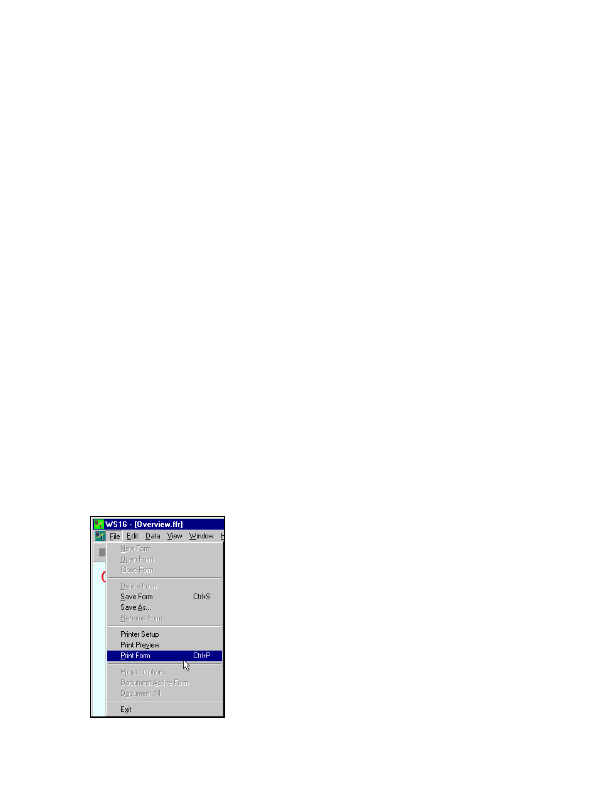
Print Form ........................................................................................................................................ 19
Project Options ................................................................................................................................ 20
Document Active Form.................................................................................................................. 20
Document All .................................................................................................................................... 20
Exit Command ................................................................................................................................. 21
EDIT MENU ........................................................................................................................................ 21
Edit Form .......................................................................................................................................... 21
Log Off and Log On ....................................................................................................................... 21
Cut ....................................................................................................................................................... 21
Copy .................................................................................................................................................... 21
Paste ................................................................................................................................................... 22
Make Form Bitmap (Normal) ...................................................................................................... 22
M-3834-0602 WMS-16STR WINDOWS GRAPHICAL SOFTWARE MANUAL.doc Page 1 of
1
Page 2

WMS-16STR Windows Graphical Page 2
Software Display Reference
Make Form Bitmap (Scaled) ........................................................................................................ 22
Set Parsing Preferences ................................................................................................................ 22
DATA MENU ..................................................................................................................................... 22
Reset Max Min Ave ......................................................................................................................... 23
Reset Change .................................................................................................................................... 23
Reset Data ......................................................................................................................................... 23
Reset All ............................................................................................................................................. 23
Reset Rain Buttons .......................................................................................................................... 23
Reset Trends ..................................................................................................................................... 23
VIEW MENU ...................................................................................................................................... 23
STANDARD WINDOW COMMANDS ................................................................................................... 24
Window Cascade ............................................................................................................................. 24
Window Tile ...................................................................................................................................... 24
Window Maximize ........................................................................................................................... 24
Child Forms ...................................................................................................................................... 25
Status Bar .......................................................................................................................................... 25
SETUP ................................................................................................................................................... 26
Setup Menu Items ............................................................................................................................ 29
File Menu .......................................................................................................................................... 29
Edit Menu .......................................................................................................................................... 29
Data Menu ........................................................................................................................................ 30
View .................................................................................................................................................... 31
COMMUNICATIONS ...................................................................................................................... 31
Communications .............................................................................................................................. 31
Communications Toolbar ............................................................................................................. 32
Real Time Monitoring Process ................................................................................................... 32
Communication Menus .................................................................................................................. 33
File Menu .......................................................................................................................................... 33
Edit Menu .......................................................................................................................................... 34
Terminal Menu ................................................................................................................................ 34
Dialer Menu ..................................................................................................................................... 35
Receiving XModem ......................................................................................................................... 36
TOOLS ................................................................................................................................................... 38
Run Mode Buttons: ......................................................................................................................... 38
Toolbar .............................................................................................................................................. 38
BACKGROUND TAB .................................................................................................................... 38
DISPLAY TAB .................................................................................................................................. 39
Special TagName Properties ....................................................................................................... 39
BUTTON (DISPLAY ONLY) ................................................................................................................. 41
Button (Show Form) ....................................................................................................................... 41
ANNUNCIATOR (ANALOG DISPLAY) ................................................................................................ 43
GLOBAL ALARM BUTTON (ANALOG DISPLAY) ............................................................................ 45
NO SPECIAL TAGNAME PROPERTIES ........................................................................................................ 48
IMAGE (DISPLAY ONLY) ..................................................................................................................... 49
SELECT IMAGE WINDOW .................................................................................................................... 50
M-3834-0602 WMS-16STR WINDOWS GRAPHICAL SOFTWARE MANUAL.doc Page 2 of
2
Page 3

WMS-16STR Windows Graphical Page 3
Software Display Reference
LABEL (ANALOG DISPLAY) ............................................................................................................... 52
Label Displays ................................................................................................................................. 52
LINE (DISPLAY ONLY) ........................................................................................................................ 54
SHAPE (DISPLAY ONLY) ..................................................................................................................... 56
SPECIAL LABEL (ANALOG DISPLAY) ............................................................................................... 57
LED INDICATOR (ANALOG DISPLAY) ............................................................................................. 59
RAIN BUTTON (ANALOG DISPLAY) ................................................................................................. 61
Rain Alarms ...................................................................................................................................... 62
TANK (ANALOG DISPLAY) ................................................................................................................. 64
Tank Properties. .............................................................................................................................. 65
BUTTON CHART (ANALOG DISPLAY) .............................................................................................. 66
Button Chart Properties (On the button) ................................................................................. 66
Trend Chart Toolbar ...................................................................................................................... 67
Setting up the Button Chart ......................................................................................................... 68
Trend Chart Property Dialogs .................................................................................................... 69
WIND SPEED & DIRECTION (ANALOG DISPLAY) ......................................................................... 75
PASSWORD ............................................................................................................................................. 77
REPORT EDITOR ............................................................................................................................. 78
GENERAL REPORT INSTRUCTIONS .................................................................................... 78
ADDING DATA PLACEHOLDERS .......................................................................................... 81
REPORT FUNCTIONS ENTERED DIRECTLY .................................................................... 82
EXAMPLE OF A SMALL REPORT .......................................................................................... 82
PRINT PREVIEW ........................................................................................................................... 83
MAIN INITIALIZATION FILE (WS16.INI) .......................................................................................... 84
PROJECT INITIALIZATION FILE .......................................................................................................... 85
PROJECTS ........................................................................................................................................... 88
Open Existing Project .................................................................................................................... 88
Create New Project ........................................................................................................................ 88
Backup Project ................................................................................................................................ 88
TRENDS ............................................................................................................................................... 89
Real Time Trends ............................................................................................................................ 89
Right Clicking .................................................................................................................................. 89
M-3834-0602 WMS-16STR WINDOWS GRAPHICAL SOFTWARE MANUAL.doc Page 3 of
3
Page 4

WMS-16STR Windows Graphical Page 4
Software Display Reference
START
Installing WS16 Display Software
1. Insert the disk(s) into your floppy disk drive.
2. Press the Windows 95, 98 or NT Start Button.
3. Select the Run Command.
4. Type A:\Setup.exe and press Enter.
5. Follow the dialog prompts.
Install WS16 in a directory of your choice (default directory is recommended).
Note: If you use the default directory, updates will install directly without directory changes.
7. Enter WS16 into your program directory.
8. Run WS16.
Welcome to WS16
WS16 Display is a Windows 95, 98 or NT software program for datalogger applications. WS16
communicates with WS16 loggers for monitoring and display of sensors and devices. WS16
provides a graphical display interface, report generator, data analysis, security, and telephone
dialer. WS16 includes the design and runtime interface in one package. There are no limits on
the number of loggers or sensor data points you can set or use. WS16 standard window’s
interface and setup tools make it easy to design new screens and reports for your application.
M-3834-0602 WMS-16STR WINDOWS GRAPHICAL SOFTWARE MANUAL.doc Page 4 of
4
Page 5

WMS-16STR Windows Graphical Page 5
Software Display Reference
WS16 screen display
General Description
WS16 is written for Windows 95, 98 or NT operating systems. Windows was chosen as the base
platform because of its multitasking capability and handling of computer resources. WS16 is an
object-oriented program: each visual component is an object (Trends, Tanks, Annunciators, LED
Displays, Images, Labels, etc.). Every component stores its own display properties and sensor
data properties. Once you have created a new component and set its properties, the program
updates the component whenever a change is measured.
Run Mode vs. Edit Mode
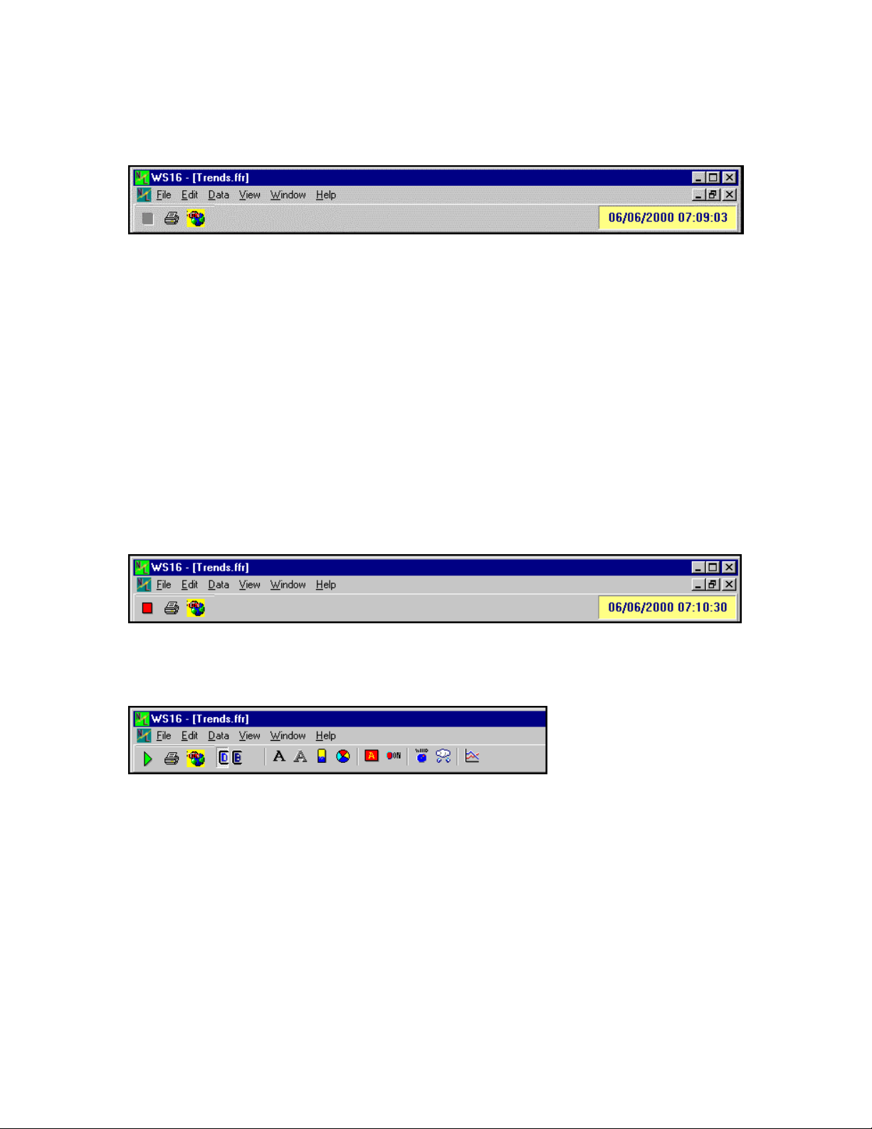
The program can be toggled from run mode to edit mode by selecting the Edit | Run menu item,
or by clicking the red square, run button. Clicking this button changes the state of the program
from Edit Mode to Run Mode. When in the edit mode certain functions are disabled until you go
M-3834-0602 WMS-16STR WINDOWS GRAPHICAL SOFTWARE MANUAL.doc Page 5 of
5
Page 6
WMS-16STR Windows Graphical Page 6
Software Display Reference
back to the run mode. To switch back to the run mode, click the green arrow or run button. You
must log on before changes can be made.
Main toolbar when logged off.
Note: The user must be logged on before the run and edit modes can be toggled on/off.
Toolbar
Creating new display objects are easy. Click once on a toolbar button in the edit mode to create a
new component. The new component is centered on the active form. To change the
component's properties, double click it to open the property form. Change it's properties to get
the look you want. When you click the update button, the new properties are applied to the
component. Drag the component anywhere on the form, resize it by selecting one of it handles
and dragging it. Nudge it by pressing the Ctrl Key and Arrow keys at the same time.
Click on the green triangle button to go back to the run-time mode. (the green triangle changes to
a red square). Click the red square Button to see tool bar.
In Run Mode
Main toolbar when logged on, in run mode.
In Edit Mode
Main toolbar when in edit mode.
This program is designed to follow many of the standard Windows mouse and keyboard
commands. In edit mode, copy a component by pressing Ctrl-C and paste it back by using
Ctrl-V. Right click the mouse button to show a popup menu. Use Ctrl + Arrow keys to
move components on the form and Shift + Arrow keys to resize existing components pixel by
pixel.
A key part of this program is learning to set the component properties to reflect what you want to
display. Once you have set the properties and closed the property form, the new properties are
stored in the component. When the program is closed, each form saves its components and their
properties.
M-3834-0602 WMS-16STR WINDOWS GRAPHICAL SOFTWARE MANUAL.doc Page 6 of
6
Page 7

WMS-16STR Windows Graphical Page 7
Software Display Reference
WS16 is a Multiple Document Interface (MDI) application. The multiple documents are the child
forms or screens you create. The main window houses all the child forms in one area, keeping
them together. You can tile, cascade, maximize, resize, and close the forms. Closing a form,
however, only minimizes it so that the components are still updated with changes. Deleting a form
deletes all its components and it’s saved file also.
There are other windows that are not child forms. These windows are either running in the
background or created when needed. The Setup, File Form and Communications Window are
always running in the background, just hidden from view. These windows are updated with new
data as they happen.
WS16 has been designed to use a minimum amount of Windows resources while running. This
will allow you to use other programs at the same time. We have had over 6 programs running at
the same time with WS16. This includes Excel, Word, Notepad, MEW (word processing),
PhotoShop, and ImageEdit. The amount of RAM in your system will affect program speed, 32
Megabytes is the minimum recommended. WS16 also runs while accessing the Internet or
CompuServe at the same time.
Important WS16 files
Main Initialization File “WS16.ini”
Project Initialization File “ProjectName.INI”
Setup Files “ResGrid.bnn & ResData.dnn”
"SetGrid.bnn & SetGrid.dnn"
Form Files “Form1.ffr”, “Summary.ffr”, "Overview.ffr", etc.
Chart Files (Chart Folder) "ButtonChart1.tee", "ButtonChart1.tdd", "ButtonChart1.INI"
Data Files (Data Folder) “Data1.txt”
Report Files “Report.rtf, MaxMinAve.rtf"
WS16 help file "WS16.hlp & WS16.cnt"
Undo_ffr Folder "Form backup when editing"
Rain Folder (Data Folder) "Rain button files"
M-3834-0602 WMS-16STR WINDOWS GRAPHICAL SOFTWARE MANUAL.doc Page 7 of
7
Page 8
WMS-16STR Windows Graphical Page 8
Software Display Reference
PROPERTIES
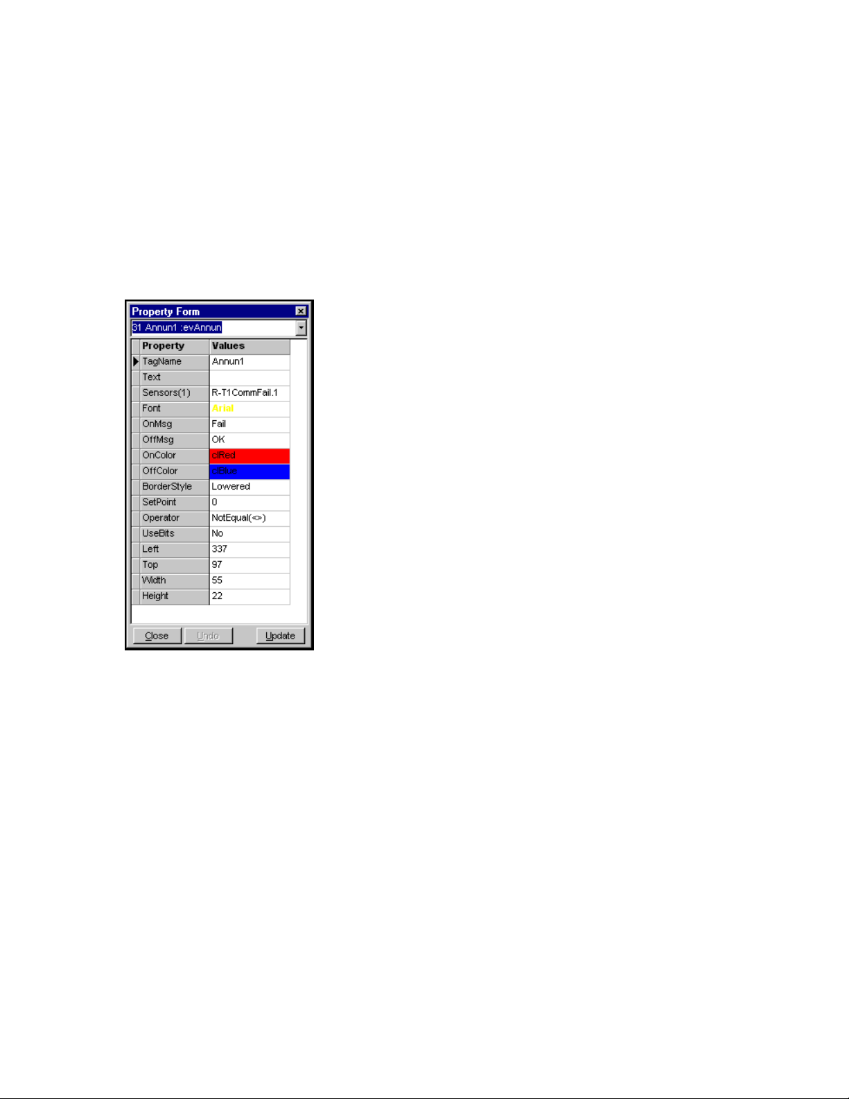
The Property Form is shown when the program is in edit mode and an object or component is
double clicked or right clicked and selecting Properties from the pop up menu will bring up the
Property Form.
Typical property box
The property form allows you to change the display characteristics of each component. You can
move it to a new location, change its font, change its text, set a sensor, etc. You can edit these
properties, update the component changes on the form, undo the changes, and press Close
button.
Some standard component properties:
Left - This is the component's left position on the form.
Top - This is the component's top position on the form.
Width - This is the component's width.
Height - This is the component's height.
Font - This is the font for the components text. Set the size, style and color.
Back Color - This is the background color for the current component.
M-3834-0602 WMS-16STR WINDOWS GRAPHICAL SOFTWARE MANUAL.doc Page 8 of
8
Page 9

WMS-16STR Windows Graphical Page 9
Software Display Reference
Other common properties are:
Title Color- set the color of the title text on the component.
On Color- the color the component becomes when the status bit is on or the bit is equal 1.
Off Color- the color the component becomes when the status bit is off or the bit is equal 0.
Fail Color- the color the component becomes when the status bit is equal 1.
Title- the component title. This value will help the user to know which component represents
which part in the system
On Message- this message is displayed when the component status bit is on.
Off Message- this message is displayed when the component status bit is off.
Fail Message- this message is displayed when the component status bit is on
Style- this option is for image components. Choose Normal, Transparent, or Masked.
Line Width- set the width of the line in pixels.
Line Slant- the line can be either Horizontal, Vertical, Slant Right, or Slant Left. Choose the
orientation for each line with this setting.
Line Color- set the color of the line here.
Angle- some components can be rotated; this setting determines how many degrees the
component is rotated
One of the best ways to set properties is to configure one component first. If the component has
the look you want, copy it and then paste it back to your form. The pasted component will have its
properties set the same as the others.
M-3834-0602 WMS-16STR WINDOWS GRAPHICAL SOFTWARE MANUAL.doc Page 9 of
9
Page 10
WMS-16STR Windows Graphical Page 10
Software Display Reference
FILE FORM
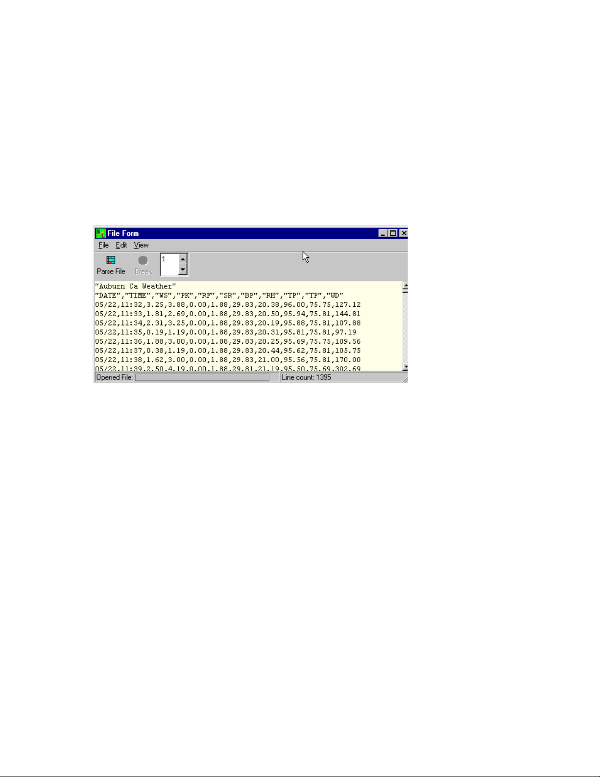
Use the File Form for historical data viewing and parsing. Parsing a file is separating the
datetime and data in each row and placing the data in the setup grids. It then updates the display
forms. It can parse a file very quickly with all the results being entered into the result grid and on
the forms.
The file form is used to view historical data that is saved on your hard disk. You can load a file and then parse it into the main program. If you reset your data, the maximums, minimums, etc will be calculated for this data set.
The file form is where historical data is loaded from a file or loaded from a logger. When data is
transfered from the memory of the logger, this form shows the results of the memory transfer.
The data can then be parsed into the program to calculate the maximums, minimums, averages.
etc.
The logger number selected will only matter if you are using more than one logger. If you have
logger 2 connected to your computer, select number 2 in this window. Then data from logger 2
will update the setup sensors that are defined for logger 2.
File Form Menu Items
M-3834-0602 WMS-16STR WINDOWS GRAPHICAL SOFTWARE MANUAL.doc Page 10 of
10
Page 11
WMS-16STR Windows Graphical Page 11
Software Display Reference
File Menu
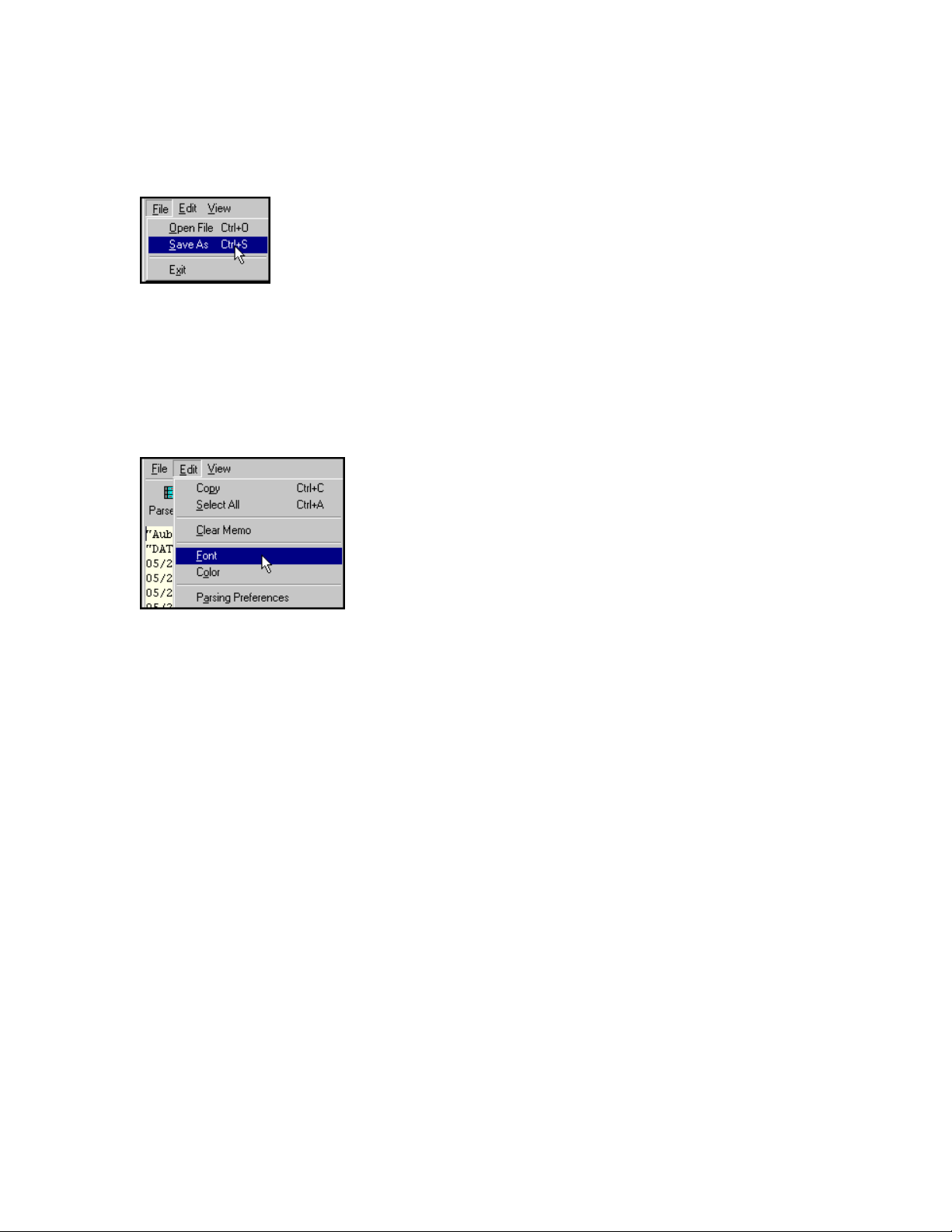
Select the file menu items; open an historical data file and parse it; save the file as a different name or exit the window.
Exit does not close the application here. It only hides the file form window.
Edit Menu
The edit menu allows you to copy or select all text, clear the memo, change the font and background color and select the Parsing Preferences.
Parsing Preferences
Parsing preferences are used when the viewing logged data after being in real time. The parsing
preferences normally reset all data summarys and trends. Then an accurate summary is created
from the new data. Each time you parse a logged file, the parsing preferences will be used. If
you want to trend several data files together, then set the preferences so that the trend data is not
reset when parsing. Then the data will be added to the data already shown in the trend.
M-3834-0602 WMS-16STR WINDOWS GRAPHICAL SOFTWARE MANUAL.doc Page 11 of
11
Page 12
WMS-16STR Windows Graphical Page 12
Software Display Reference
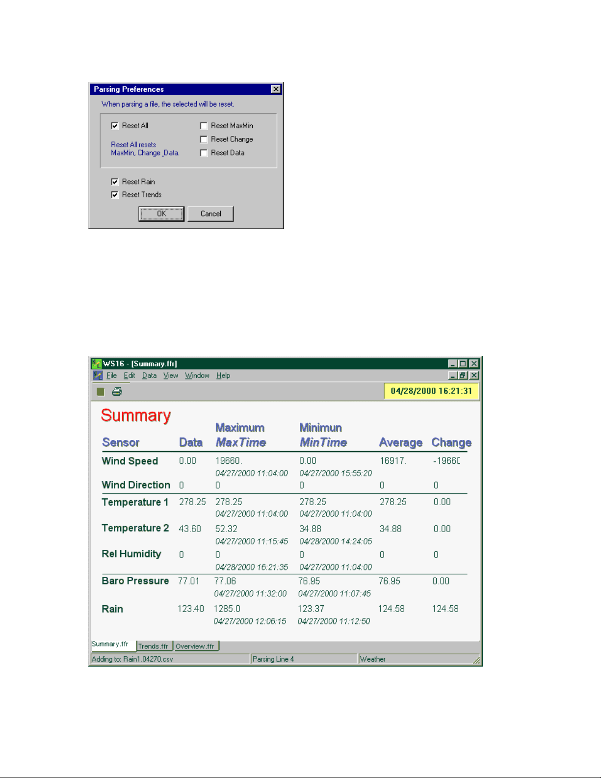
Select the parsing preferences needed.
FORMS
Form Files are saved as binary files with a *.ffr extension. Form files are child windows which are
created by selecting File | New Form from the menu. See Editing Forms for more information on
building forms.
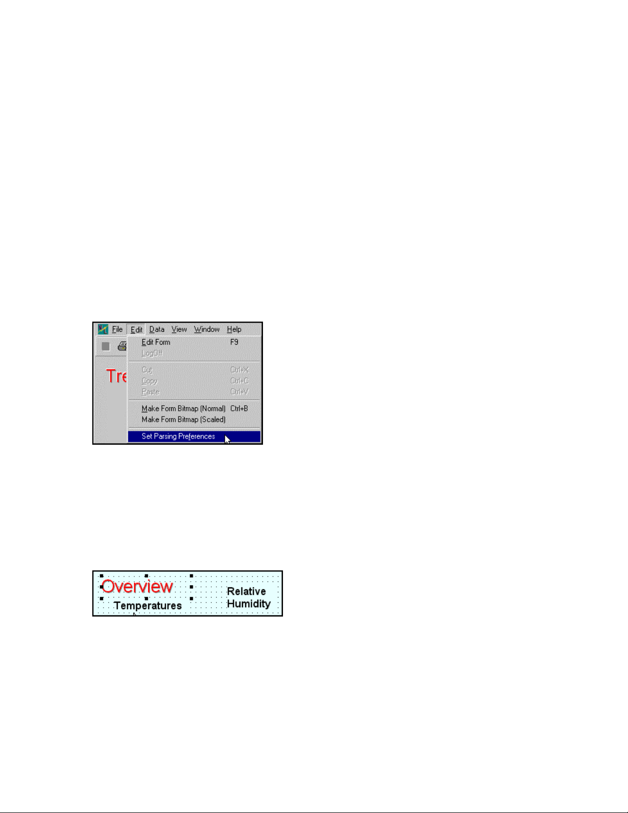
WS16 Form displays
M-3834-0602 WMS-16STR WINDOWS GRAPHICAL SOFTWARE MANUAL.doc Page 12 of
12
Page 13
WMS-16STR Windows Graphical Page 13
Software Display Reference
The form files are stored in the project directory and referenced by name in the project
initialization file.
The tabs at the bottom of the forms provide another means of accessing each form in the project.
The selected form will be shown in white and the other forms will be in gray. Just click on any of
the tabs to see that form.
EDITING FORMS
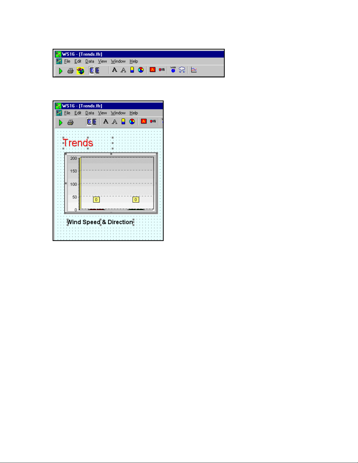
To edit a form you can click on select the Edit | Edit Form menu item or press F9, or click on the
red square in the tool bar. A password to edit forms and communications is required before
editing is possible.
Edit Form or F9 menu item
FORM EDITING
The background shows a grid in edit mode and the green arrow is showing with the toolbar. Click
the green arrow to go back into the run mode.
Select a component in the edit mode by clicking on it. Selected components have handles around them.
When in the edit mode, the form background changes to a dotted background. If a bitmap image
is covering the background, there will be no visible change.
M-3834-0602 WMS-16STR WINDOWS GRAPHICAL SOFTWARE MANUAL.doc Page 13 of
13
Page 14
WMS-16STR Windows Graphical Page 14
Software Display Reference
Form in edit mode. Press the Green Arrow Button to back to run mode.
Select multiple components by clicking the form with the left mouse and
dragging until a rectangle is shown. The components touched by the
rectangle will become selected. You can also click on one component
and then shift-click to add or subtract components to the group.
The editing mode allows you to edit the forms and components. If the current user has
permission to edit forms, the Red Square Button on the toolbar will be enabled and the menu
item, Edit | Edit Forms will be enabled.
Click the Red Square Button or select the menu item and you will be in the edit mode. The Red
Square Button has changed to a green arrow. Clicking on the green arrow starts the
communications again and the program goes back into run mode.
M-3834-0602 WMS-16STR WINDOWS GRAPHICAL SOFTWARE MANUAL.doc Page 14 of
14
Page 15
WMS-16STR Windows Graphical Page 15
Software Display Reference
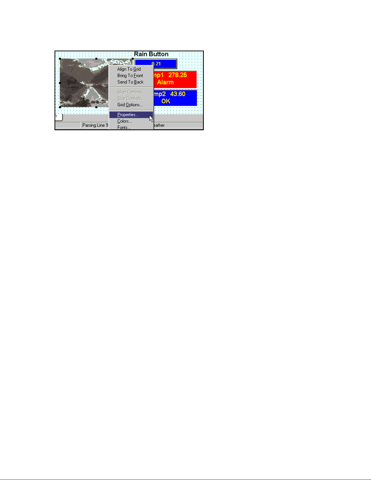
Use the right mouse button to click on one of the selected components.
A popup menu will allow you to align controls, size controls, bring to the
front, or send to the back. Use the right click to select the properties of
one component without moving it on the form.
Note: The cut, copy and paste commands are only enabled when the form is in edit mode.
If you go back to the run mode, components that have been copied or cut will be removed from clipboard.
Cut
The Cut menu item or Ctrl-X can be used to remove a component from the form in the edit
mode. When you cut a component from a form it can be pasted back to the same form or to any
other form. Multiple components can be cut, copied or pasted.
Copy
The Copy menu item or Ctrl-C is very similar to the Cut command. To copy a component to
the clipboard, select the component and press Ctrl-C or select the menu Edit | Copy. This is
done only in the Edit Mode. You can then paste Ctrl-V the component back to the form as
many times as needed.
Paste
The Paste menu item or Ctrl-V is used along with Copy and Cut. When a component is copied
to the clipboard (by the Copy or Cut command), that component can be pasted back to the form
by pressing Ctrl-V or selecting the menu item. Multiple copies of one component can be pasted
to one or more forms. Just use the Ctrl-V command to paste the copied component as many
times as needed.
Note: The object copied is clear when you go out of the edit mode. If you want to paste between forms, copy the component and click on the new form tab and then paste it. The component will be pasted into the selected form.
Nudging
M-3834-0602 WMS-16STR WINDOWS GRAPHICAL SOFTWARE MANUAL.doc Page 15 of
15
Page 16

WMS-16STR Windows Graphical Page 16
Software Display Reference
You can nudge components if they are selected. Just press the Ctrl + Arrow Keys. You can also
resize the component (pixel by pixel) by using the Shift + Arrow Keys. If multiple components are
selected, all components will be moved or resized.
Make Form Bitmap (Normal)
Make form bitmaps copies the current form into the clipboard for pasting into reports. The main
problem with this method may be the width of the bitmap (usually to big). Use this method if you
want to paste the bitmap into a paint program or other program for editing.
Make Form Bitmap (Scaled)
Make form bitmap scaled copies the current form into the clipboard and resizes the bitmap to fit
into an existing report width (about 7"). Use this option if you want to make a report with the form
image as part of the report.
M-3834-0602 WMS-16STR WINDOWS GRAPHICAL SOFTWARE MANUAL.doc Page 16 of
16
Page 17
WMS-16STR Windows Graphical Page 17
Software Display Reference
MENU ITEMS
The following items are listed in order as they are seen within the program (from the top of the
main window to the bottom).
Title Bar
Program Icon (Icon at top left of WS16 program)
Caption: WS16 - [Form Name]
If a child window is maximized then caption reads: WS16 - [Form Name]
Minimize Button, Maximize Button, Close Button
If you click on the program icon a standard Windows menu is displayed. This menu item includes
standard window command:
Restore, Move, Size, Minimize, Maximize and Close.
Menu Items
The menu items allow you to view different forms and make changes to your program. Buttons on
the toolbar duplicates some of the menu items. If you like using the keyboard, you can press the
Alt key and the underlined letter to access a menu item.
File Menu
M-3834-0602 WMS-16STR WINDOWS GRAPHICAL SOFTWARE MANUAL.doc Page 17 of
17
Page 18

WMS-16STR Windows Graphical Page 18
Software Display Reference
Several menu items are disabled. This is because the user is not logged on to the system. No changes can be made until the user logs on.
New Form
The New Form menu item creates a new form. This item is enabled only if the current security
level allows it. Once a form is created it becomes part of the application until it is deleted.
Note1: When a form is created the application names it: Form1.ffr. You should rename the form
by clicking on the File | Rename Form. Enter your new form name and click OK. When the
application is closed, the form will be saved with this name. Save the current form with the
selecting the Save Form menu item or using the key command Ctrl S.
Note2: You can also save the form by doing a File | SaveAs. This saves the form with the new
name and doesn’t change the original form. To duplicate forms, use the SaveAs command.
Open Form
The Open Form menu item opens a form file (*.ffr). If the file is already opened then it open a
copy of the form. You can open forms from other projects into your application. Be sure to
rename the form if your form is a copy of another form or if the form name is the same as another
form in your project.
The opened form becomes part of the project when saved or when the application is closed.
Close Form
The Close Form menu item closes the active child form and removes it from your project. It does
not delete it from the project folder. You will be prompted that this form will be closed from the
project. Select yes if you really want to close it from the project.
Delete Form
The Delete Form menu item deletes the form from the project and also deletes the form file from
the project directory. Use the delete command if you want to delete this file from your project and
from the hard disk.
Save Form
M-3834-0602 WMS-16STR WINDOWS GRAPHICAL SOFTWARE MANUAL.doc Page 18 of
18
Page 19

WMS-16STR Windows Graphical Page 19
Software Display Reference
The Save Form menu item saves the current form to disk, creating a .ffr file. The form name is
the form's caption or title. You can use the rename form command at any time to rename the
current form to a more meaningful name. Use keyboard command "Ctrl S" to save at any time.
Save As
The Save As menu item saves the current form as a new form.ffr file. Use the Save As form
command when you want to make a duplicate of a form. This is useful if many of your sites are
the same. You can then open the new form into your project for editing. You can open any
existing form again by using the open form command. It makes a copy for you and opens it in
your project.
Rename Form
The Rename Form menu item renames the current form and its corresponding “.ffr” file.
When a new form is created it is named Form1.ffr. You can rename the form to a more
meaningful name by using the rename command. None of the components are changed or
checked, since it is using an existing form.
Printer Setup
The Printer Setup menu item allows you to the select and configure the printer for this application.
Print Preview
The Print Preview menu item pops up a print preview screen to show the form to be printed. You
can cancel the print job or select Print Form.
Print Form
The Print Form command is used to print the entire active form. If you only want a portion of the
form you can resize the form first to show only the items you want to print and then select print
form. Print form will print the form as soon as you select it.
Note: Be sure to check your default printer if you are using more than one printer. Use the printer
setup command to do this.
M-3834-0602 WMS-16STR WINDOWS GRAPHICAL SOFTWARE MANUAL.doc Page 19 of
19
Page 20
WMS-16STR Windows Graphical Page 20
Software Display Reference
Project Options
WS16 loads the last project opened when started. A project is a group of screens, and setup files
stored in a project folder. You can open other projects from this menu item as well as back up
your existing project (recommended). See the projects section for a complete description.
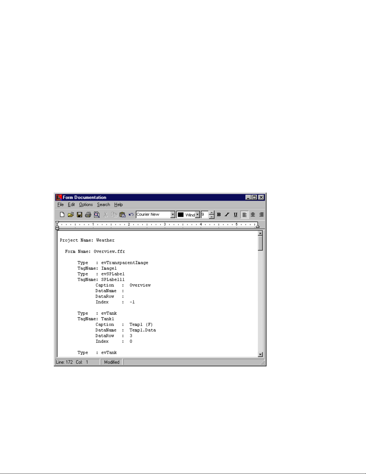
Document Active Form
Document Active Form loads the report form with a list of the project name, and the active form
with all components. Important component’s properties are shown. Use this menu command to
check your forms and to keep a record of your forms. The report can be saved or printed.
Form documentation
Document All
The Document All menu command loops through all the forms and documents each screen or
form. The output is presented as a report. You can save it or print it.
M-3834-0602 WMS-16STR WINDOWS GRAPHICAL SOFTWARE MANUAL.doc Page 20 of
20
Page 21
WMS-16STR Windows Graphical Page 21
Software Display Reference
Exit Command
The Exit menu item closes the application and automatically saves the child forms and
components. You do not have to save the forms individually. The program saves it for you. The
exit command also writes to the WS16.ini file and the Project.ini file. These files are used to
reopen the project as you left it.
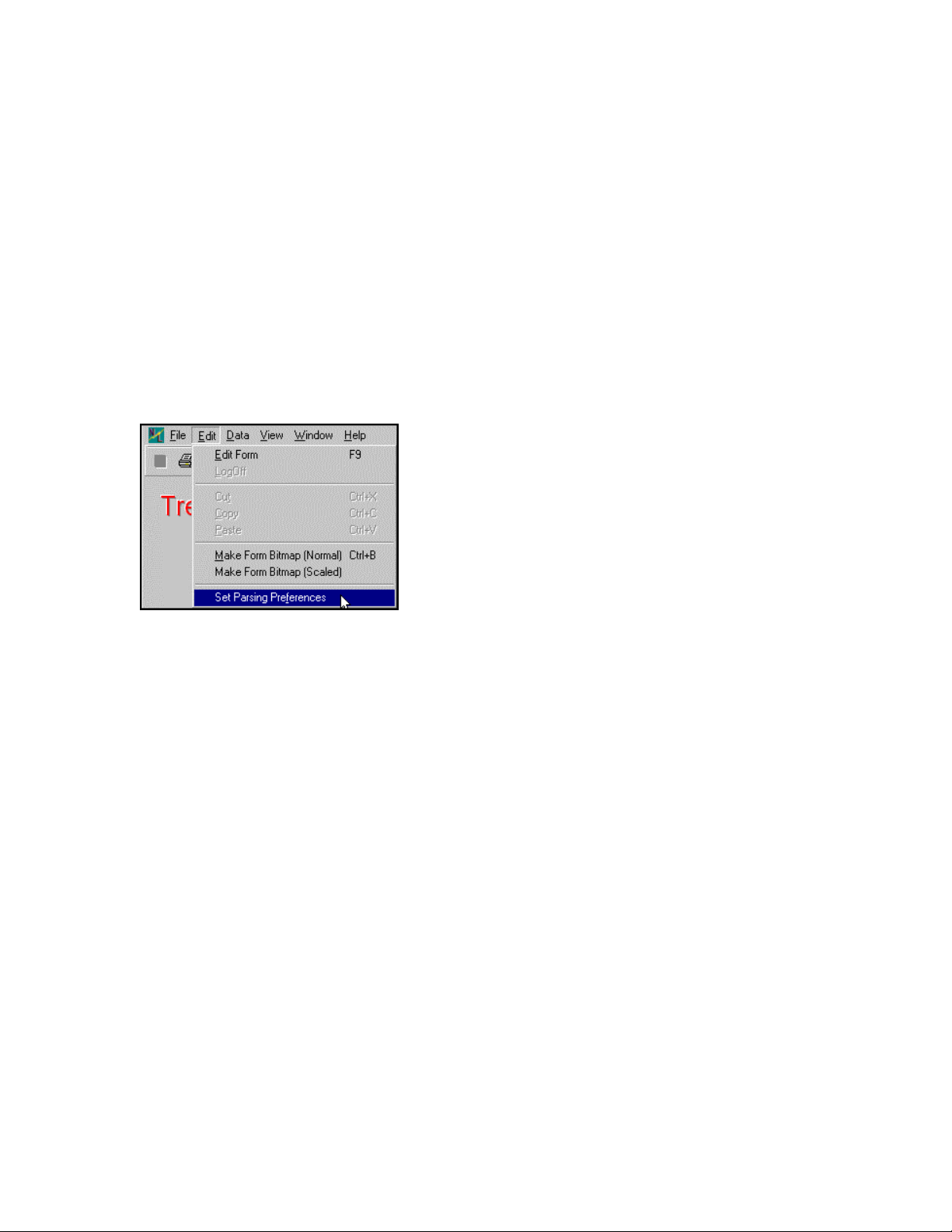
EDIT MENU
Main form editing menu options
Edit Form
The edit form is a toggle from editing to run mode. You can only go into the edit mode if you have
the correct password.
Log Off and Log On
Logging off requires the password be entered again to do any editing.
Cut
The Cut menu item or Ctrl-X can be used to remove a component from the form in the edit
mode. When you cut a component from a form it can be pasted back to the same form or to any
other form. Multiple components can be cut, copied or pasted.
Copy
The Copy menu item or Ctrl-C is very similar to the Cut command. To copy a component to
the clipboard, select the component and press Ctrl-C or select the menu Edit | Copy. This is
done only in the Edit Mode. You can then paste Ctrl-V the component back to the form as
many times as needed.
M-3834-0602 WMS-16STR WINDOWS GRAPHICAL SOFTWARE MANUAL.doc Page 21 of
21
Page 22
WMS-16STR Windows Graphical Page 22
Software Display Reference
Paste
The Paste menu item or Ctrl-V is used along with Copy and Cut. When a component is copied
to the clipboard (by the Copy or Cut command), that component can be pasted back to the form
by pressing Ctrl-V or selecting the menu item. Multiple copies of one component can be pasted
to one or more forms. Just use the Ctrl-V command to paste the copied component as many
times as needed.
Make Form Bitmap (Normal)
Make form bitmaps copies the current form into the clipboard for pasting into reports. The main
problem with this method may be the width of the bitmap (usually to big). Use this method if you
want to paste the bitmap into a paint program or other program for editing.
Make Form Bitmap (Scaled)
Make form bitmap scaled copies the current form into the clipboard and resizes the bitmap to fit
into an existing report width (about 7"). Use this option if you want to make a report with the form
image as part of the report.
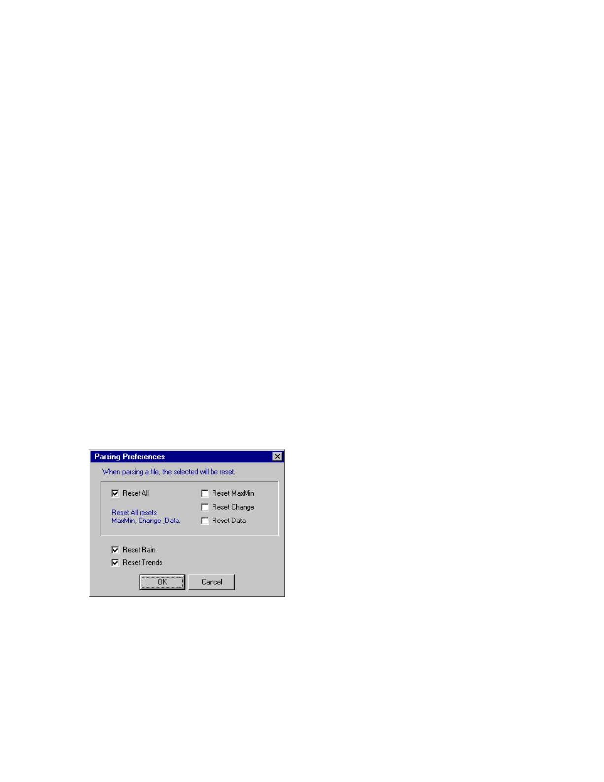
Set Parsing Preferences
Parsing preferences are used when the program goes from monitoring in real time to historical
data analysis. You normally will use the reset all data option, reset trends and rain buttons when
processing an historical data file.
Select this dialog to set the parsing preferences.
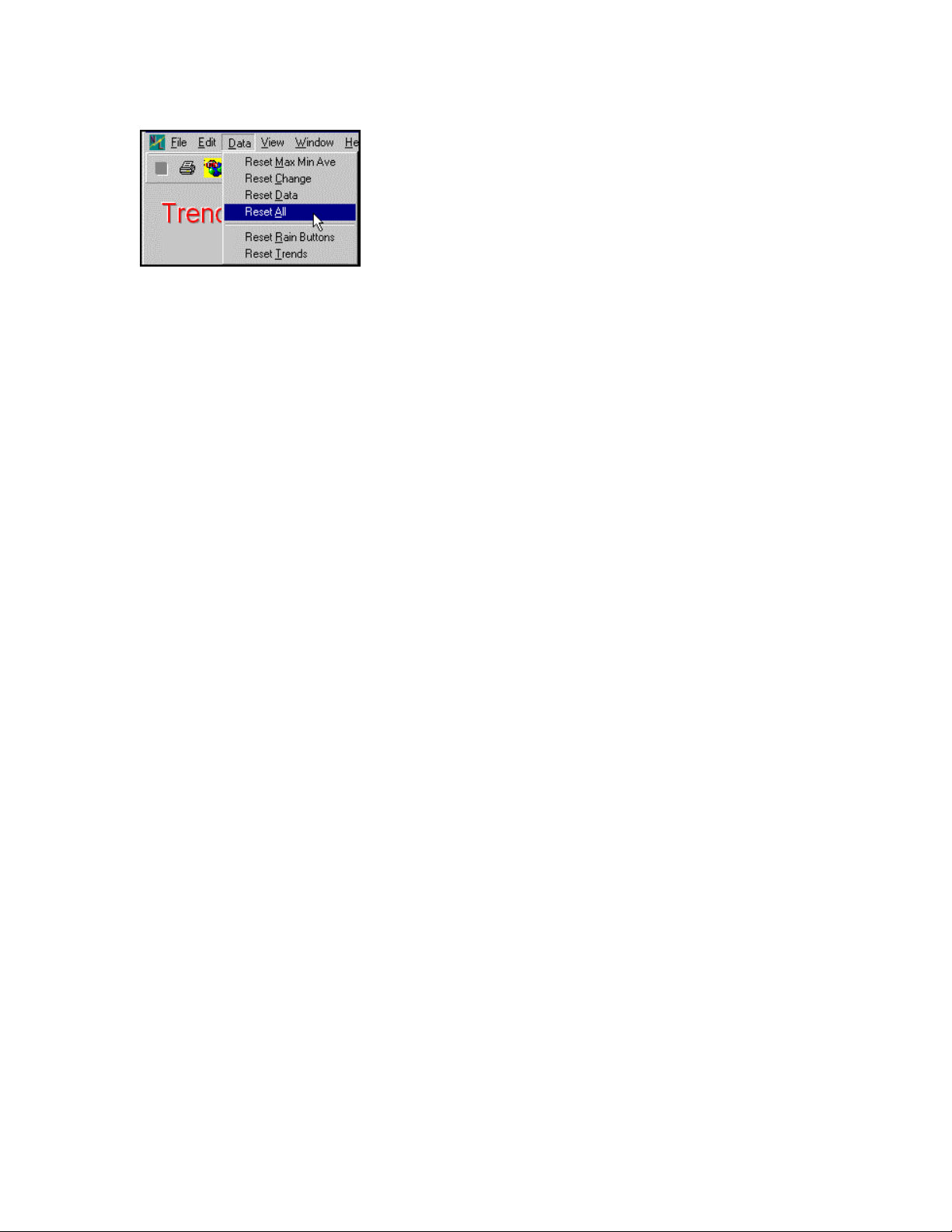
DATA MENU
M-3834-0602 WMS-16STR WINDOWS GRAPHICAL SOFTWARE MANUAL.doc Page 22 of
22
Page 23
WMS-16STR Windows Graphical Page 23
Software Display Reference
Reset Max Min Ave
Resets the maximum, minimum and average values. These are reset at midnite every day.
Reset Change
Resets the change values. These are reset at midnite also.
Reset Data
Reset the data values only. These are not reset at midnite.
Reset All
Resets all of the above (max, min, ave, change, and data).
Reset Rain Buttons
Resets the form rain buttons. If the WS16 has been running for a long period of time and the
software is started and stopped on a regular basis, the rain button totals will be wrong. The rain
button totals are only correct if you run the program at all times monitoring the rain. Reset the rain
button if the totals look incorrect.
Reset Trends
Resets the form trend values. The trends should be reset if the data being loaded has the same
dates as the existing data or has older dates. If you want to see more than one set of logged data
then don't reset the trends.
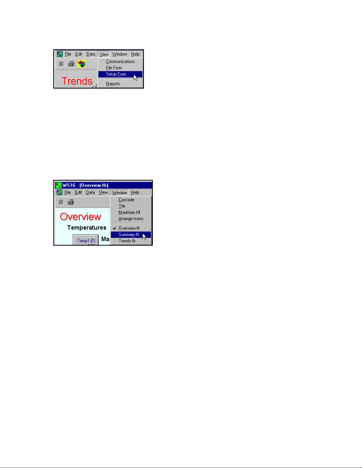
VIEW MENU
M-3834-0602 WMS-16STR WINDOWS GRAPHICAL SOFTWARE MANUAL.doc Page 23 of
23
Page 24
WMS-16STR Windows Graphical Page 24
Software Display Reference
View menu items
The view menu provides access to many important windows. The setup and communication
window, and Reports are selected from here.
Standard Window Commands
Wndow menu items
Window Cascade
Window | Cascade performs the standards Windows cascading function. The forms will be
cascaded downward and to the right.
Window Tile
Window | Tile performs the standard windows Tile function. This arranges the windows side by
side in the main window.
Window Maximize
Window | Maximize All maximizes all of the forms in the project.
M-3834-0602 WMS-16STR WINDOWS GRAPHICAL SOFTWARE MANUAL.doc Page 24 of
24
Page 25
WMS-16STR Windows Graphical Page 25
Software Display Reference
Child Forms
The forms shown below the menu and tool bar are MDI Child Windows. These are your real time
screens with display components. Forms, screens, windows, displays are all MDI child windows.
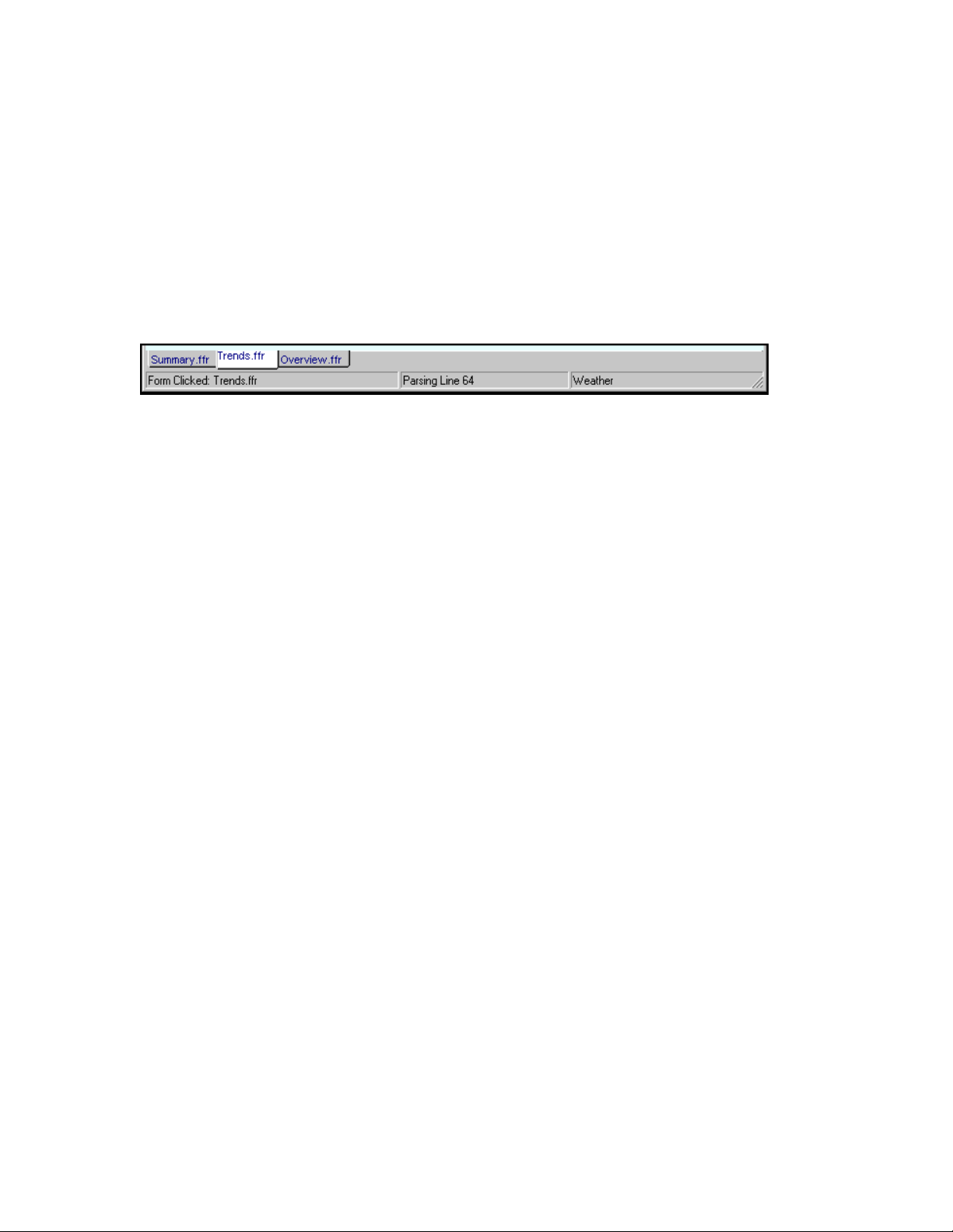
Status Bar
Status bar and form tabs.
Panel 1: Display system status messages.
Panel 2: Displays communication messages.
Panel 3: Current project name.
See Toolbar
M-3834-0602 WMS-16STR WINDOWS GRAPHICAL SOFTWARE MANUAL.doc Page 25 of
25
Page 26
WMS-16STR Windows Graphical Page 26
Software Display Reference
SETUP
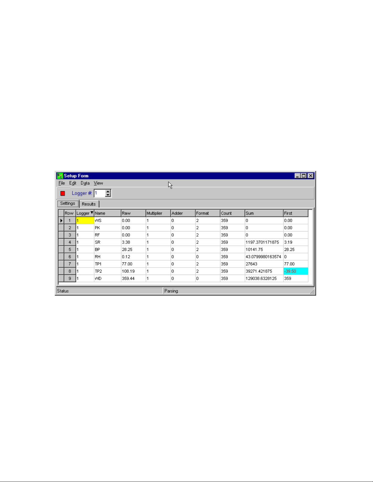
You can access the Setup Form from the Main Form by selecting the menu View |
Communications or View | Setup. Both menu items will display the Setup Form. Sensor setup,
data results and communications is done in the setup form.
The Setup Form has 3 tabs:
1. Settings
2. Results
The Setup Form showing the Settings Tab.
Note: The order of the sensors in the Settings Grid is important. When data is received from the
WS16 communications, it is parsed into date, time, data1, data2, data3, .... dataN. Data1 is
placed into the raw column, first row of the Settings Grid. Data2 is placed into the 2nd row, Data3
into the 3rd row, etc. The number of sensors assigned in the WS16 enclosure should be the
same as the number of rows in the Settings Grid.
When in the edit mode, you can change items in the Settings Grid. The Results Grid is calculated
from the settings in the Settings Grid. The raw column and time column are input from the
communications parsing. When the program is in the monitoring mode, each line is parsed into
the appropriate time and raw data columns. The raw data is changed into engineering units and
placed into the results data column. The program then calculates the average, maximum,
minimum and change for each sensor. These data values are available for reports and form
displays.
Setting you can change:
1. Name (use default names as much as possible). Form components and reports use names to
get data from the results grid. If the names are the same as the defaults, components will not
M-3834-0602 WMS-16STR WINDOWS GRAPHICAL SOFTWARE MANUAL.doc Page 26 of
26
Page 27

WMS-16STR Windows Graphical Page 27
Software Display Reference
have to be changed and will display data properly. Default names (names are case sensitive) are
the same as the xmodem transfer title names:
a. WS (wind speed) and PK (peak wind)
b. WD (wind direction)
c. TP1 (temperature 1)
d. TP2 (temperature 2)
e. RH (relative humidity)
f. BP (barometric pressure)
g. RF (rain fall)
h. SR (solar radition)
These names are entered when you want default names inserted into your grid. These names
can be in any order or rows. Names should not be duplicated. The data from a duplicated name
will always show the first row of the name.
2. Multiplier (normally 1).
3. Adder (normally 0).
4. Format (normally 2). This is the number of decimal places shown. (0=4, 1=4.1, 2 = 4.12;
3=4.123).
5. Count, Sum and First are calculated by the program. These values are used the maximum,
minimum, average and change calculations. You don't need to set these values.
M-3834-0602 WMS-16STR WINDOWS GRAPHICAL SOFTWARE MANUAL.doc Page 27 of
27
Page 28
WMS-16STR Windows Graphical Page 28
Software Display Reference
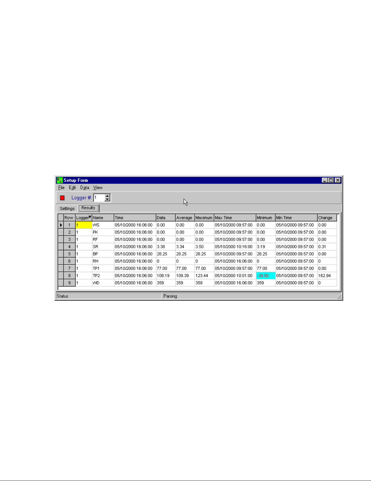
The results grid showing columns for Name, Time, Data, Average, Maximum, MaxTime, Minimum, MinTime, & Change.
Components are assigned sensor names to show data.
The results sensor names are as follows:
1. 1.TP1.Time 1=logger number, TP1=sensor name, Time=column selected.
2. 1.TP1.Data
3. 1.TP1.Average
4. 1.TP1.Maximum
5. 1.TP1.MaxTime
6. 1.TP1.Minimum
7. 1.TP1.MinTime
M-3834-0602 WMS-16STR WINDOWS GRAPHICAL SOFTWARE MANUAL.doc Page 28 of
28
Page 29
WMS-16STR Windows Graphical Page 29
Software Display Reference
8. 1.TP1.Change
Each defined sensor defaults into the 8 sensors listed above. Any of these values can be
displayed or placed in a report.
Setup Menu Items
File Menu
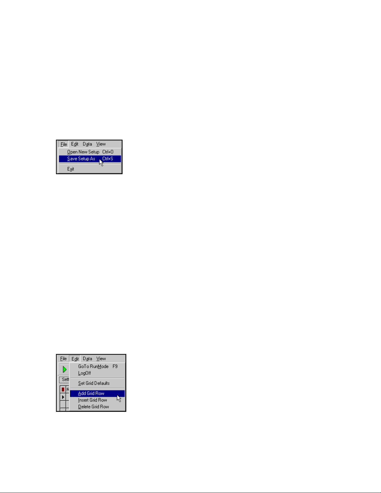
The file menu items, Open a data file for parsing, save setup as, and save the communications memo as.
Open Data File
Selecting this menu item, stops the current parsing and opens a data file for parsing. If the file is
formated properly, it will be parsed and the data will be input into the results grid and the forms will
be updated with the file values.
Save Setup As
Use this option to make a duplicate of your current grid settings. Use a different name than the
default names.
Exit
Hides the Settings Form. If parsing is on, it will continue in the background.
Edit Menu
The Edit Menu Items are used for editing the grid settings and clear the communications menus.
Goto EditMode or Goto RunMode
M-3834-0602 WMS-16STR WINDOWS GRAPHICAL SOFTWARE MANUAL.doc Page 29 of
29
Page 30
WMS-16STR Windows Graphical Page 30
Software Display Reference
You have to enter a password before you can enter the edit mode. If the password was already
entered, you will go directly into the edit mode.
Log Off
Logging off means you will have to enter the password again to edit forms and sensor settings.
Set Grid Defaults
Set the grid defaults, sets the names and default parameters for the standard weather station.
Only do this if you need to go back to the default settings.
Add, Insert and Delete Grid Rows
Add a grid row adds a row to the end of the grid.
Insert a row inserts a row above the cursor.
Delete a row deletes the row the cursor is in.
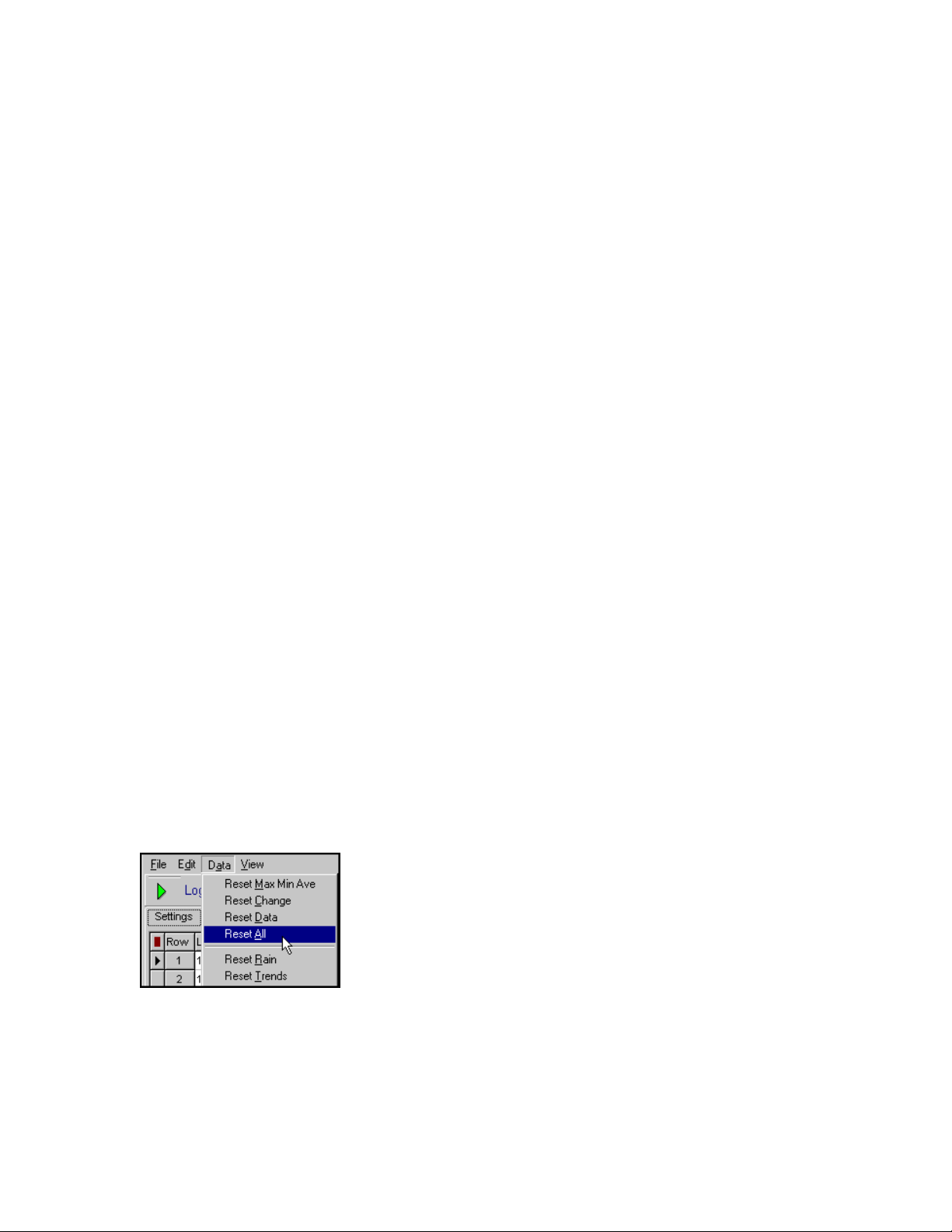
Data Menu
Use the data menu to reset maximums, minimums, averages and changes.
Use this menu to reset the rain buttons and trends.
The Data menu is used to reset the statistic information that is calculated during the day. These
values are normally reset at midnite. Rain and trends are not reset at midnite.
M-3834-0602 WMS-16STR WINDOWS GRAPHICAL SOFTWARE MANUAL.doc Page 30 of
30
Page 31

WMS-16STR Windows Graphical Page 31
Software Display Reference
View
You can go back to the main form using this menu item.
COMMUNICATIONS
Communications
The communications with the WS16 logger is easy to setup and use. The program must be set at
the same communication parameters as the WS16 logger. Once this has been done and your
communications port is open, you can press an enter key in the memo window to see a menu
from the logger. Select the logger options necessary to either download XModem data or view
real time data.
M-3834-0602 WMS-16STR WINDOWS GRAPHICAL SOFTWARE MANUAL.doc Page 31 of
31
Page 32
WMS-16STR Windows Graphical Page 32
Software Display Reference
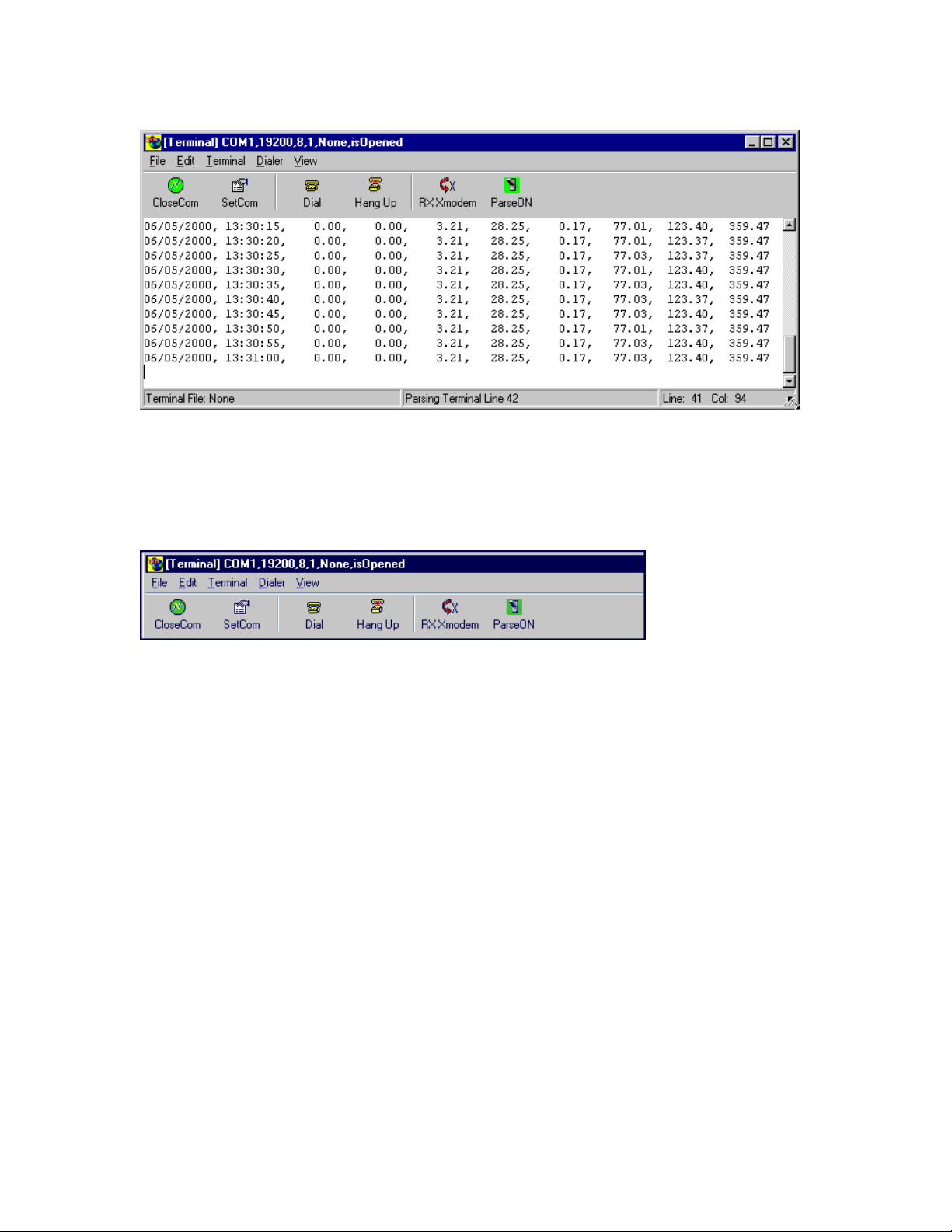
Communications memo showing data that has been parsed and entered into the settings and result grid.
Communications Toolbar
Many of the communication function are handled by clicking a the toolbar buttons.
You can open or close the communications port.
You can set the communication parameters.
You can dial out to a remote logger and then hang up.
You can receive an Xmodem file from a direct connect logger or modem logger.
You can toggle the parsing of real time data on or off.
Real Time Monitoring Process
M-3834-0602 WMS-16STR WINDOWS GRAPHICAL SOFTWARE MANUAL.doc Page 32 of
32
Page 33
WMS-16STR Windows Graphical Page 33
Software Display Reference
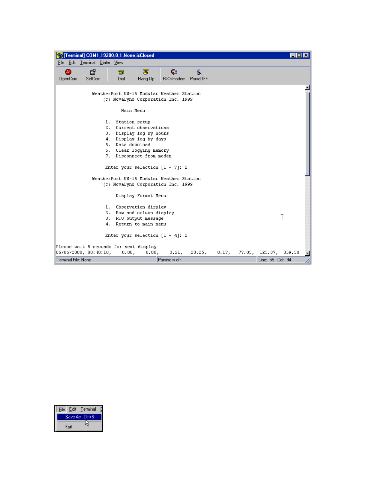
The WS16 logger menu selections for real time data processing.
Click the enter key in the terminal window.
The logger will present you with a menu.
Select the menu items shown above to go into real time monitoring.
Normally, you would press 2, Enter, and 2, Enter to go into this mode.
Communication Menus
Many of the menu items duplicate the functions of the toolbar.
File Menu
M-3834-0602 WMS-16STR WINDOWS GRAPHICAL SOFTWARE MANUAL.doc Page 33 of
33
Page 34
WMS-16STR Windows Graphical Page 34
Software Display Reference
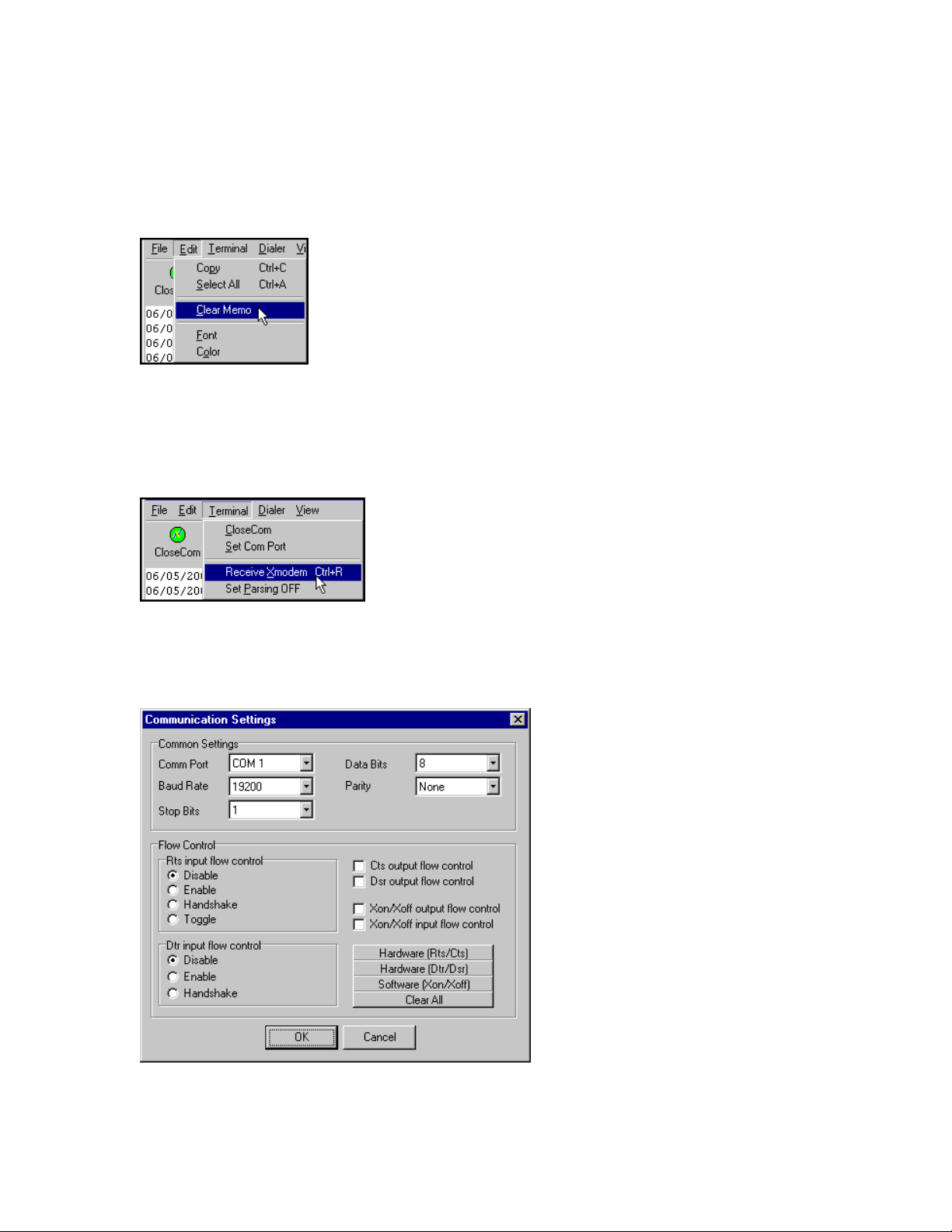
Save the terminal meno text as a file and exit. Exit does not stop the communications.
Edit Menu
Select part of the text or select all, copy to clipboard for pasing into another editor. Clear memo, change font and
background color.
Terminal Menu
Use the terminal menu to set the communication parameters, open or close the comport, start xmodem, and toggle the
parsing on or off.
Set ComPort
Select this option to change communication parameters. Standard parameters are Com1,9600 baud, 8 bits, 1 stop bit,
and no parity,
M-3834-0602 WMS-16STR WINDOWS GRAPHICAL SOFTWARE MANUAL.doc Page 34 of
34
Page 35
WMS-16STR Windows Graphical Page 35
Software Display Reference
Open or Close the Communications Port
This option opens or closes the current communications port.
Set Parsing On or Off
Toggles the communication parsing on or off. If the WS16 is sending 5 second data, parsing
should be turned on to update the defined sensors. The parsing is automatically turned off when
a file is opened for parsing. Once you go back to the 5 second data mode, you can toggle the
parsing on again.
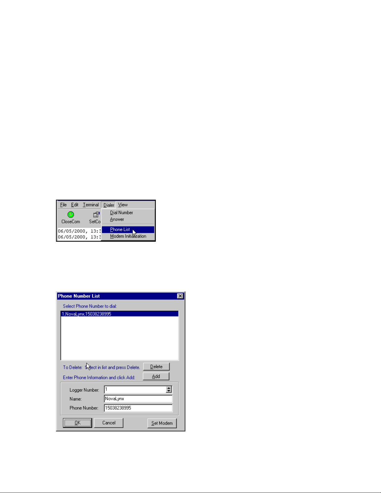
Dialer Menu
Dial a phone number, answer on 1 ring, set your dialout phone list and set modem initialization.
Phone Number List
Enter phone numbers and logger reference here. This dialog is presented to you for selecting a phone number when you
dial.
M-3834-0602 WMS-16STR WINDOWS GRAPHICAL SOFTWARE MANUAL.doc Page 35 of
35
Page 36
WMS-16STR Windows Graphical Page 36
Software Display Reference
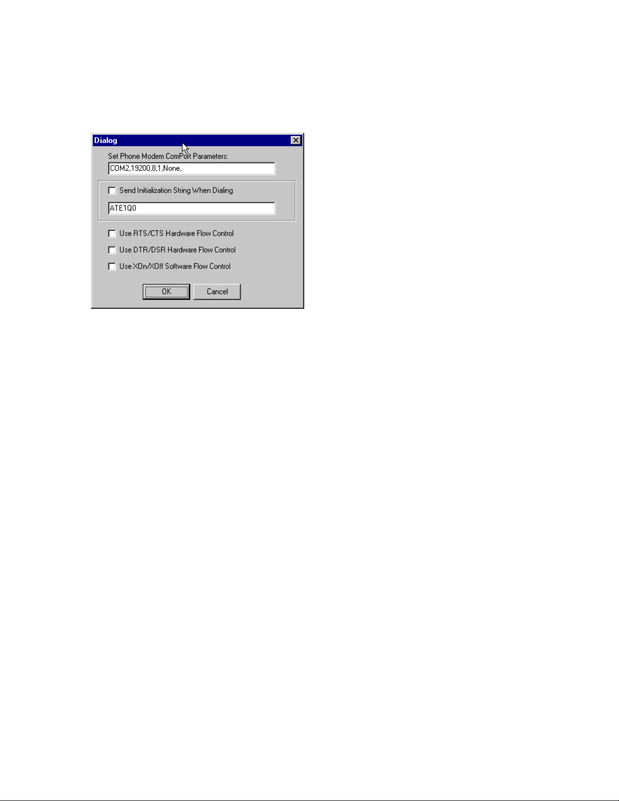
Modem Initialization
Set the phone modem port and dialout parameters here. Also send an initialization string to the modem if necessary.
There are two communication ports being used by WS16 Display. The first port is normally the
direct connect port. A WS16 logger should be connected to this port. The second port is the
modem port. These settings are used when connecting to a logger via modem.
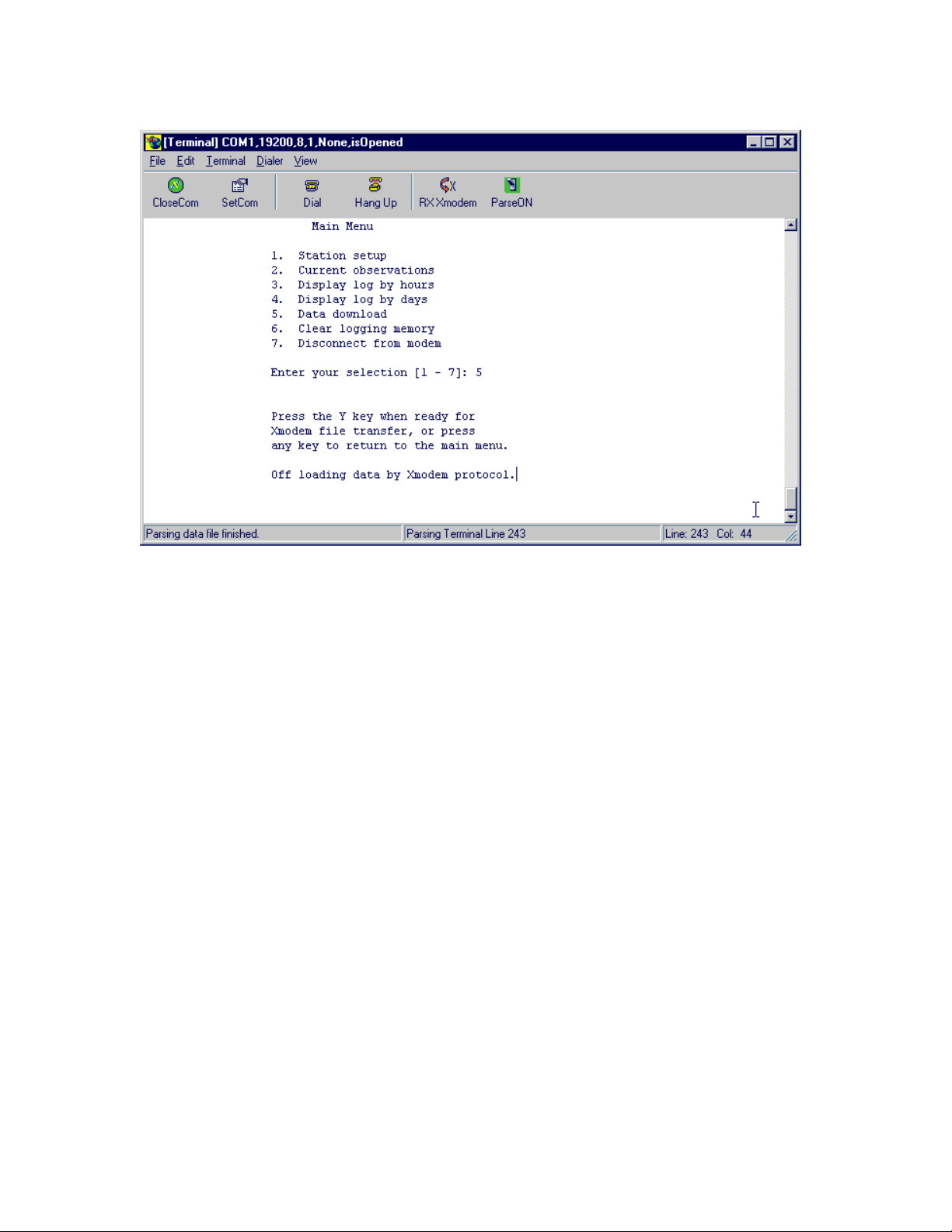
Receiving XModem
M-3834-0602 WMS-16STR WINDOWS GRAPHICAL SOFTWARE MANUAL.doc Page 36 of
36
Page 37
WMS-16STR Windows Graphical Page 37
Software Display Reference
When you have selected the proper menu items you can receive the historical data file from the WS16 logger.
You can cancel the Xmodem process by pressing the break button.
M-3834-0602 WMS-16STR WINDOWS GRAPHICAL SOFTWARE MANUAL.doc Page 37 of
37
Page 38
WMS-16STR Windows Graphical Page 38
Software Display Reference
TOOLS
Run Mode Buttons:
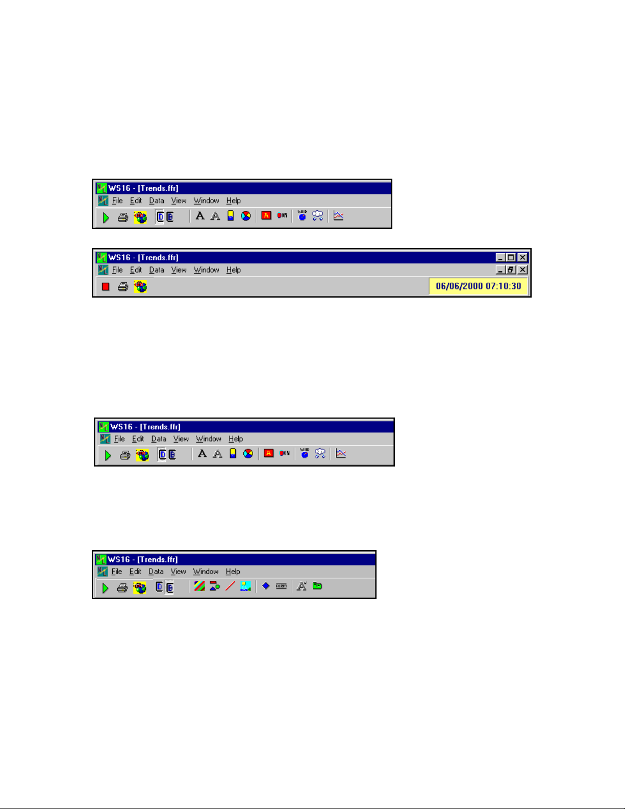
Green Button (Arrow): WS16 is in the Edit Mode, click on to enter the run mode.
Red Button (Square): WS16 is in the Run Mode, click on to enter the edit mode.
The third yellow button selects the communications window.
Toolbar
Toolbar: Display Tab Selected
Labels, Special Labels, Tanks, Chart Buttons, Annunciators, LED,
Wind Speed & Direction, and Rain Button
Toolbar: Background Tab Selected
Form Color, Shapes, Lines, Images (bitmaps, wmf, ico), Global Alarm Button, Buttons, Click Labels, Tabs
BACKGROUND TAB
Form Color, Shapes, Lines, Images (bitmaps, wmf, ico), Global Alarm Button, Buttons, Click Labels, Tabs
Properties Display Analog
Background Color form color no
M-3834-0602 WMS-16STR WINDOWS GRAPHICAL SOFTWARE MANUAL.doc Page 38 of
38
Page 39

WMS-16STR Windows Graphical Page 39
Software Display Reference
Shape yes no
Line yes no
Image yes no
Global Alarm Buttons yes yes
Form Button yes no
Click Label yes yes
Form Tab yes no
DISPLAY TAB
Labels, Special Labels, Tanks, Chart Buttons, Annunciators, Pumps, Valves, LEDs, Polygon,
Rain Button and Wind Speed & Direction, Rain Button
Properties Display Analog
Label yes yes
Special Label yes yes
Tank yes yes
Button Chart yes yes
Annunciator Display yes no
LED Display yes no
Wind Display yes yes
Rain Button yes yes
Change Background
The multicolored background button.
The Change Background Color button allows the user to change the background color on the
current form. A color dialog box will be displayed to select and change colors.
Select the form and click on this button to change its background color.
Special TagName Properties
M-3834-0602 WMS-16STR WINDOWS GRAPHICAL SOFTWARE MANUAL.doc Page 39 of
39
Page 40

WMS-16STR Windows Graphical Page 40
Software Display Reference
The TagName property is an identifier that originally had to be unique for every component.
When WS16 went to the grid configuration for Modbus settings, the TagName property no longer
had to be unique. The TagName property became available for special purposes.
We are using the TagName to set special properties for some components. The Annunciator
uses the TagName property to show the data value as well as a text message. The Edit box and
other controls use the TagName property for limiting access and allowing access to this control
when no user is logged on.
These special properties were add to the TagName property so that older systems would still be
compatible with newer changes. If a special property is defined it will be listed in the component's
definition.
M-3834-0602 WMS-16STR WINDOWS GRAPHICAL SOFTWARE MANUAL.doc Page 40 of
40
Page 41

WMS-16STR Windows Graphical Page 41
Software Display Reference
Button (Display Only)
Button (Show Form)
The button component is used to go to another form in the project.
To add a button to the current form, click on the 'Add Button' button on the Controls tab of the
toolbar. The button is a component that allows the user to switch between forms in Run Mode.
Simply select a form in the Buttons tab, and in Run Mode, the user can switch between forms.
This is useful for making a main form and links to the main form and other forms.
M-3834-0602 WMS-16STR WINDOWS GRAPHICAL SOFTWARE MANUAL.doc Page 41 of
41
Page 42
WMS-16STR Windows Graphical Page 42
Software Display Reference
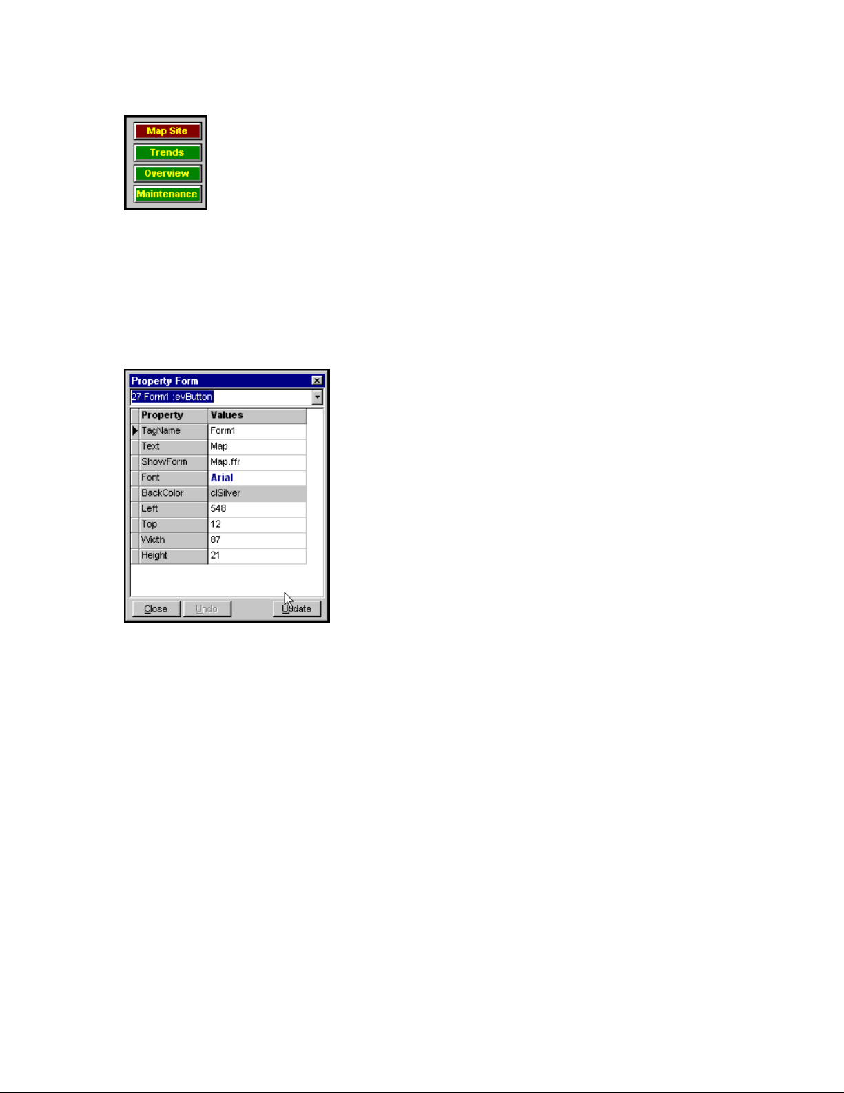
Click a button to go to another form.
To modify the properties of any component, double click it, and the Property Form will open.
Button properties
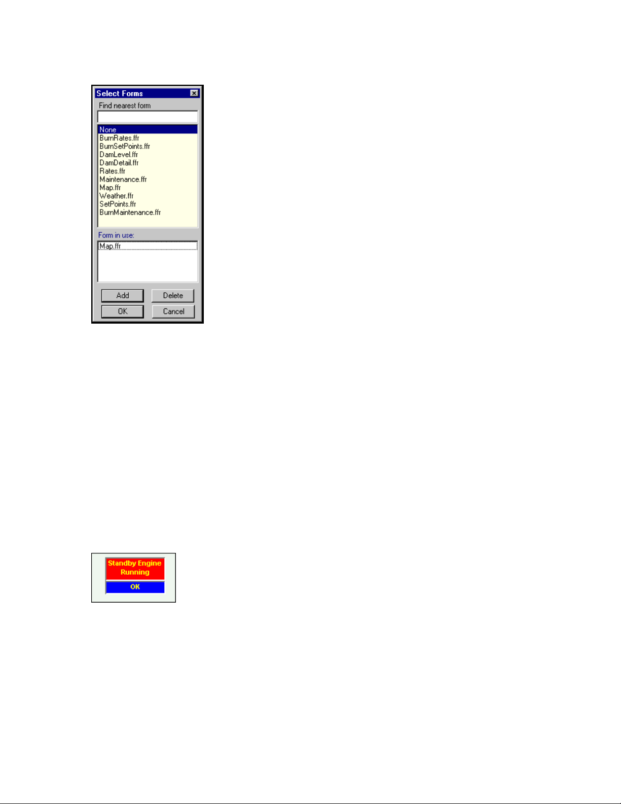
Selecting a form To open from Button properties
M-3834-0602 WMS-16STR WINDOWS GRAPHICAL SOFTWARE MANUAL.doc Page 42 of
42
Page 43
WMS-16STR Windows Graphical Page 43
Software Display Reference
Selecting a form to show when the button is clicked
No Special TagName Properties
Annunciator (Analog Display)
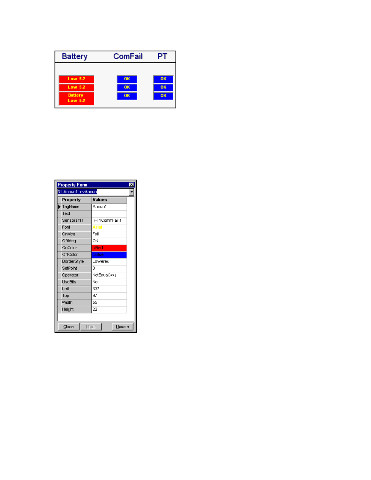
Use the annunciator display to show bit changes or analog value alarms. The back color changes
and the message changes. The annunciator display can be shown using only the top message
(half size). Just delete the text message and leave the alarm messages. Then resize the
component smaller. Click on the annunciator button is the display tab to add it to the form.
M-3834-0602 WMS-16STR WINDOWS GRAPHICAL SOFTWARE MANUAL.doc Page 43 of
43
Page 44
WMS-16STR Windows Graphical Page 44
Software Display Reference
Two line annunciator and one line annunciator with alarm messages.
The annunciator component changes colors based on analog set points or status bit on-off
values. Use it to display on, off, or fail conditions for triggers, pumps, valves, or other bit values.
The annunciator can also compare an analog value to a set point value. Analog comparisons
include less than <, greater than >, or not equal <>. The text message is shown in the top line
and the OnMsg/OffMsg is displayed in the bottom line.
List of Annunciator properties.
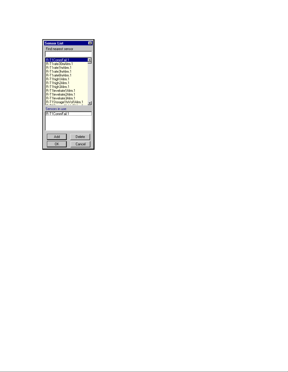
Sensor List Selection from Annunciator Properties
M-3834-0602 WMS-16STR WINDOWS GRAPHICAL SOFTWARE MANUAL.doc Page 44 of
44
Page 45
WMS-16STR Windows Graphical Page 45
Software Display Reference
Sensor list selection
Annunciator Special TagName Properties ( put in the TagName property (use lowercase) )
1. valuetop (shows value only, top line) value (shows value only, bottom line)
2. valuetop+ (shows text message and value) value+ (shows On/Off message and value)
3. Blank text line for bottom line message only.
M-3834-0602 WMS-16STR WINDOWS GRAPHICAL SOFTWARE MANUAL.doc Page 45 of
45
Page 46
WMS-16STR Windows Graphical Page 46
Software Display Reference
Global Alarm Button (Analog Display)
The global alarm button serves three purposes. It can be used as a display item, it can be used
as a button, and it can be used as an alarm button.
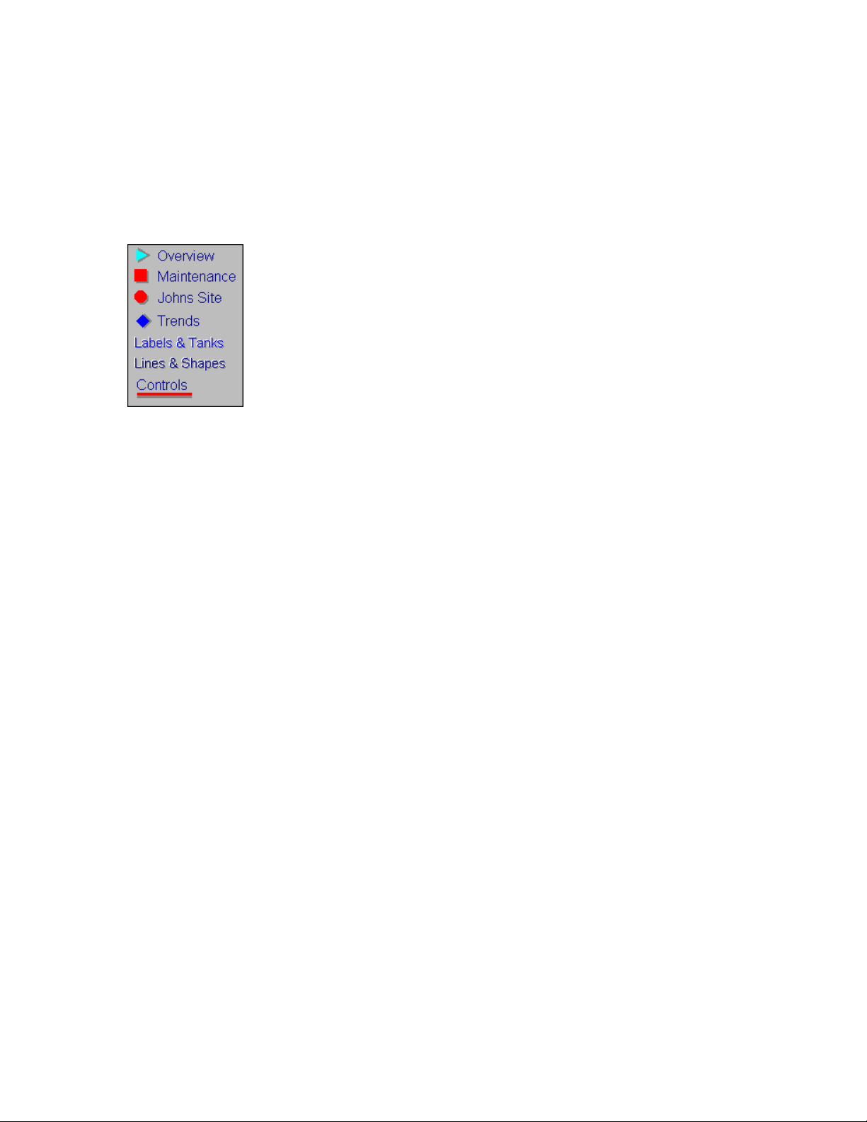
Global alarm button shapes, can also be text
Display Only:
The global alarm button can be configured in 7 different shapes. The shapes are rectangle,
rounded rectangle, Ellipse, Diamond, Triangle, Line and Text. To use the component as a display
only, don't enter a show form name and select none for the data source. You can change the
shapes and colors of the component to show the effect needed.
Display and Button Only:
The global alarm button can be configured to open any form or window that has been created.
Just select one of the form.ffr names in the Show Form selection box. Now when you click on it,
you will bring a new form to the front of the screen.
Display, Button and Alarm:
The global alarm button can be configured to have a sensor address that changes colors when
the value is greater than, or less than, or not equal to a set point.
In many systems, there is an alarm word that is divided into 16 bits. Each bit is an individual
sensor alarm for that site. If all the bits are off, the word will have a value of zero (0). If any bit is
on or in alarm, the bit will be non zero and the data will be a value greater than zero (>0). By
selecting a sensor and the operator (< >) and a set point, the global alarm button will change
colors when the sensor is not equal to the set point.
This feature can be used with any analog value. The global alarm button is handy on system
maps or overviews where you want to see if there are any alarms in the system, if there is an
alarm, the button will change to the On Color and you can click on it to go to the selected form.
To add a global alarm button to the current form, click on the Add Global Alarm Button on the
Controls tab of the toolbar.
Once a sensor is assigned to the component, along with the operator (< or >) and set point, the
component will display the On Color and Off Colors. The normal button color is the Off Color.
M-3834-0602 WMS-16STR WINDOWS GRAPHICAL SOFTWARE MANUAL.doc Page 46 of
46
Page 47
WMS-16STR Windows Graphical Page 47
Software Display Reference
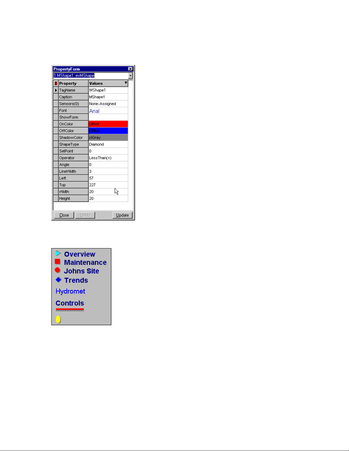
To modify the properties of any component, double click it, and the Property Form will open.
Global Alarm Button property screens
Global alarm button shapes, and colors. Text can also be a global alarm button.
Show Form- select which form will be brought to the front when this button is clicked in Run
Mode
On Color- this property is for Global Alarm Buttons. The component will be this color when the
specified alarm is on.
Off Color- this property is for Global Alarm Buttons. The component will be this color when the
specified alarm is off.
M-3834-0602 WMS-16STR WINDOWS GRAPHICAL SOFTWARE MANUAL.doc Page 47 of
47
Page 48

WMS-16STR Windows Graphical Page 48
Software Display Reference
Shape- set the shape for the global alarm button (Circle, Diamond, Ellipse, Rectangle, Round
Rectangle, Triangle, Line, Text).
Border Width- set the width of the outline of the button.
Operator- this operator is used to determine an analog alarm. Choose whether the alarm state of
the component is when its value is less than the set point (<), or greater than the set point (>) or
(<>) not equal to the set point.
Set Point- the analog value with which the current value will be compared to determine alarms.
The alarms are for display only. Use the file and alarms to log historical alarms.
No Special TagName Properties
M-3834-0602 WMS-16STR WINDOWS GRAPHICAL SOFTWARE MANUAL.doc Page 48 of
48
Page 49
WMS-16STR Windows Graphical Page 49
Software Display Reference
Image (Display Only)
Use Images for form backgrounds. Special image effects are masking and transparent modes.
Try these looks to see what looks the best.
Use Images for backgrounds to enhance your screen display
To add an imagee to the current form, click on the Add Image button on the Displays tab of the
toolbar. This will open up the Select Image Window. Three types of files may be opened by
WS16: .bmp, .ico (icon), and .wmf files. Only these files will be displayed in the file selection
boxes. Use a map image as the background of a screen, or any other image to graphically
enhance your screens.
Select or copy an Image for a form background
Image Properties
Display Left, Top, Width, Height, Style, Stretch, AutoSize, Image Masked
M-3834-0602 WMS-16STR WINDOWS GRAPHICAL SOFTWARE MANUAL.doc Page 49 of
49
Page 50
WMS-16STR Windows Graphical Page 50
Software Display Reference
The masked option masks the bitmap image. The image cannot be stretched in this mode.
Masked is effective for window backgrounds.
Image Transparent: The transparent option takes the color of the bottom left hand pixel, and
makes that color transparent through the image.
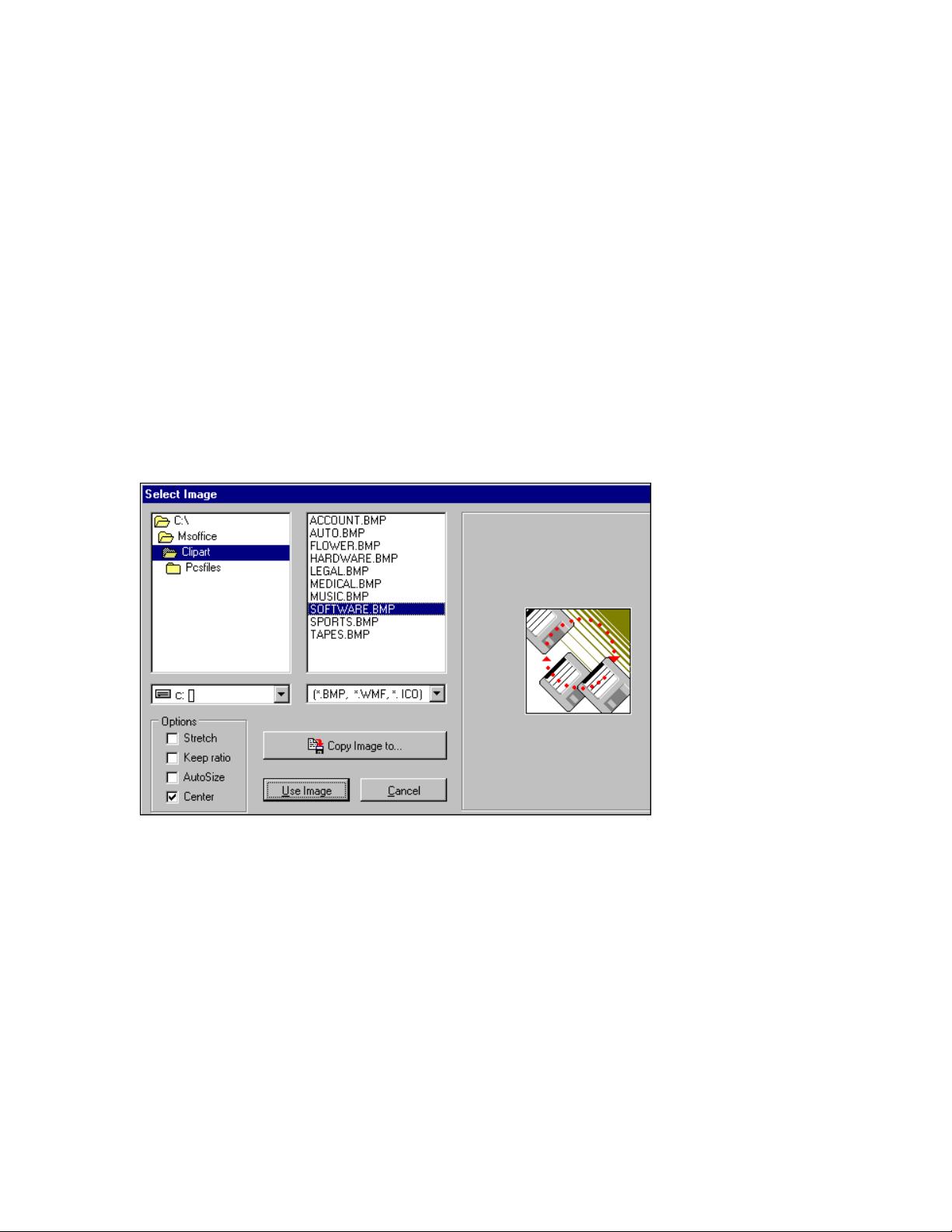
Select Image Window
The Select Image Window is opened when the Add Image button is clicked. Use the directory list
to select the directory of the graphic file to be added. Four types of files may be opened: bitmap
(*.bmp), icon (*.ico), enhanced window metafiles (*.emf), and windows metafiles (*.wmf). Only
files with these extensions will show up in the file box. Click on a file to preview the image in the
window on the right.
Directory list on left, bitmap images on right, click on image to use.
Copy an image into your form by selecting the image and then pressing Use Image button.
Options- the options box allows the user to preset some of the properties of the image.
Copy Image To- Click this button to copy the selected image file to another directory. This
feature is helpful because all image files should be kept in the project directory. If you find an
image to use elsewhere on the hard drive or on a floppy disk, use the Copy Image To button to
copy it into the project directory. This button will open a standard Save As dialog where the file
can be saved anywhere.
Use Image- Click this button when you have found and selected the image you want to use.
M-3834-0602 WMS-16STR WINDOWS GRAPHICAL SOFTWARE MANUAL.doc Page 50 of
50
Page 51

WMS-16STR Windows Graphical Page 51
Software Display Reference
Cancel button- Click the cancel button to close the image window and to cancel the selection of
an image.
Note: clicking on the Cancel button after copying files will not undo the files that have been copied.
M-3834-0602 WMS-16STR WINDOWS GRAPHICAL SOFTWARE MANUAL.doc Page 51 of
51
Page 52
WMS-16STR Windows Graphical Page 52
Software Display Reference
Label (Analog Display)
Label Displays
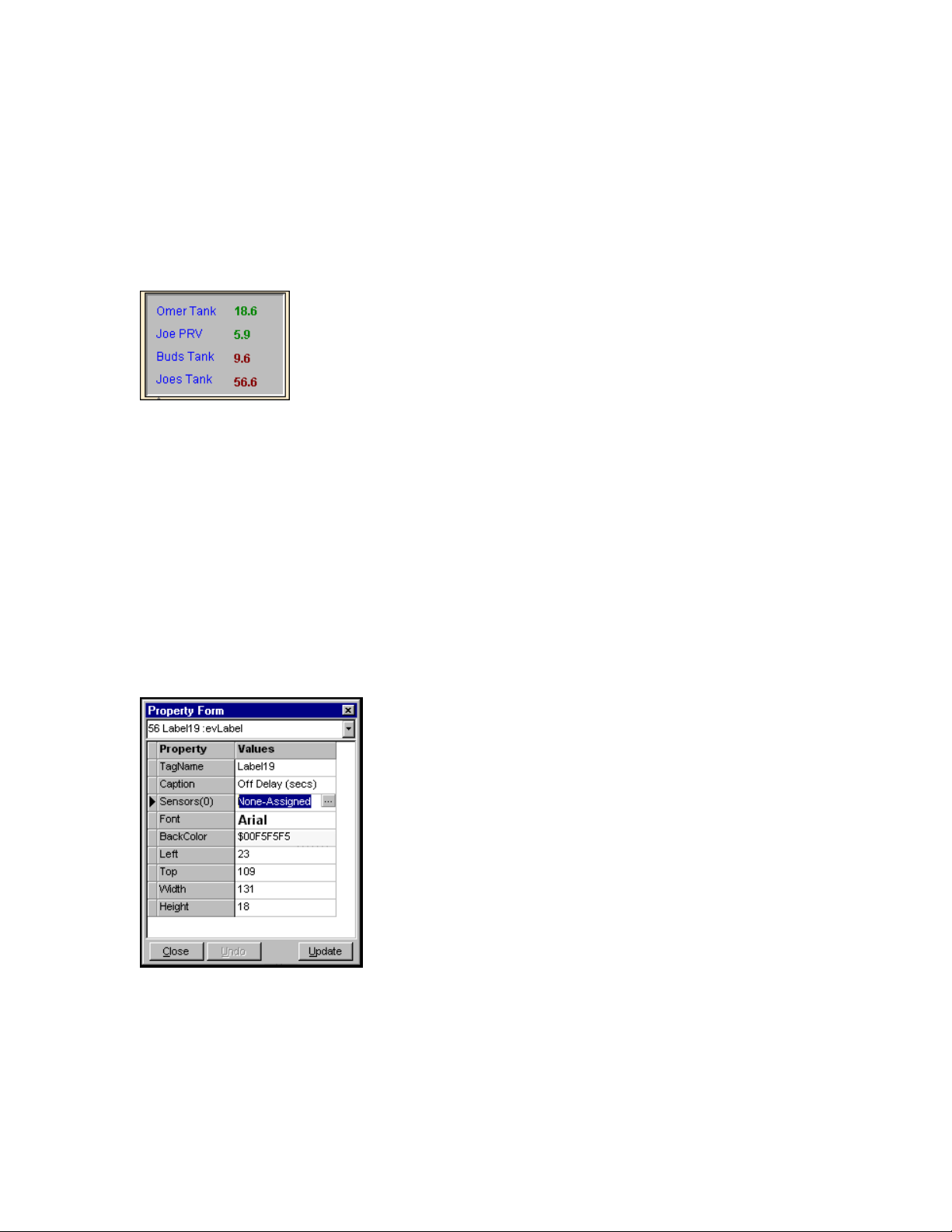
Labels can be used to show data or text
Labels are used to display analog values received by the master as well as regular text label
displays. Labels can be used to show the results of the equation function also.
To add a label to the current form, click on the Add Label Button on the Displays tab of the
toolbar. The label is a component capable of displaying sensor values or user set values. One
label might display the level of a tank, another might say 'Main Valve' serving as a caption.
To modify the properties of any component, double click it and the Property Form will open.
Label properties
No Special TagName Properties
M-3834-0602 WMS-16STR WINDOWS GRAPHICAL SOFTWARE MANUAL.doc Page 52 of
52
Page 53

WMS-16STR Windows Graphical Page 53
Software Display Reference
M-3834-0602 WMS-16STR WINDOWS GRAPHICAL SOFTWARE MANUAL.doc Page 53 of
53
Page 54
WMS-16STR Windows Graphical Page 54
Software Display Reference
Line (Display Only)
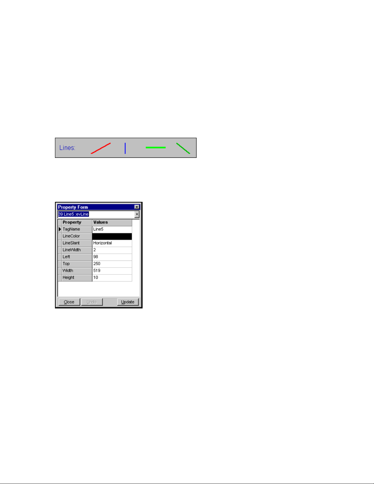
Lines and lines with arrows are used for display purposes only.
To add a line to the current form, click on the Add Line button on the Displays tab of the toolbar.
Lines are for graphical use only; they cannot be used to display sensor values.
Lines can be different colors and widths. See special tagname properties to add arrows to one or both ends.
To modify the properties of any component, double click it, and the Property Form will open.
Line property box
Special TagName Properties (Arrows add names in lowercase )
arrowleft LineSlant=Horizontal, draws arrow on left.
LineSlant=Vertical, draws arrow on top.
LineSlant=SlantLeft, draws arrow on left.
LineSlant=SlantRight, draws arrow on right.
arrowright LineSlant=Horizontal, draws arrow on right side.
LineSlant=Vertical, draws arrow on bottom.
LineSlant=SlantLeft, draws arrow on right.
M-3834-0602 WMS-16STR WINDOWS GRAPHICAL SOFTWARE MANUAL.doc Page 54 of
54
Page 55

WMS-16STR Windows Graphical Page 55
Software Display Reference
LineSlant=SlantRight, draws arrow on left.
arrowleftright Draws an arrow on both ends of the line component.
M-3834-0602 WMS-16STR WINDOWS GRAPHICAL SOFTWARE MANUAL.doc Page 55 of
55
Page 56
WMS-16STR Windows Graphical Page 56
Software Display Reference
Shape (Display Only)
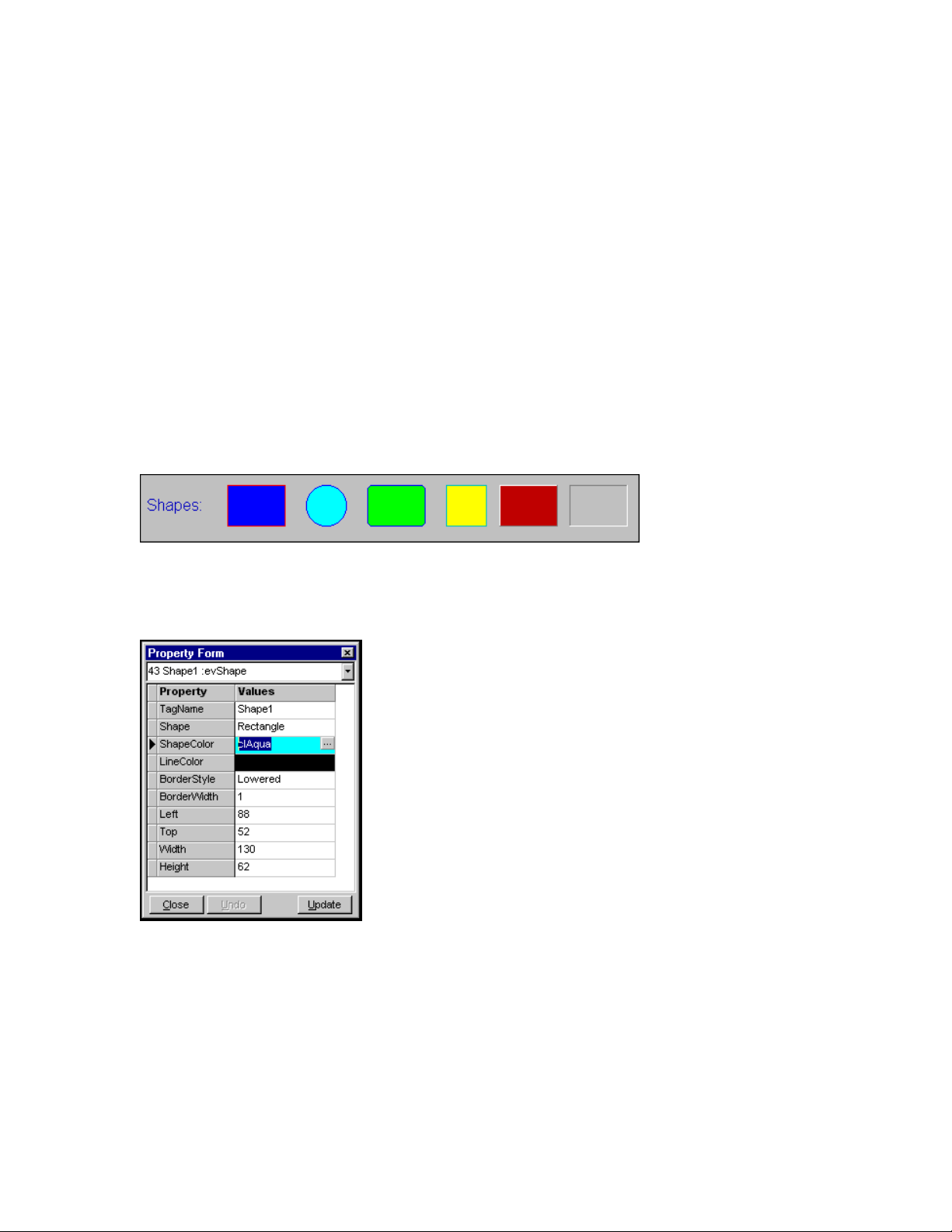
Shapes are used for display purposes only. You can right click a new shape and send it to the
back, if it is on top of another component.
To add a shape to the current form, click on the Add Shape Button on the Displays tab of the
toolbar. The shape will default to a rectangle, but it can be changed to a Circle, Ellipse, Round
Rectangle, Round Square, or Square. A shape can serve only as a graphical component; it does
not perform any functions or calculations. Shapes work well as pipes connecting tanks, pumps,
and valves and for grouping labels in one area of the form.
Use a shape as a background for a group of components.
Rectangles, circles, rounded rectangles, squares, raise rectangles, lowered rectangles.
To modify the properties of any component, double click it, and the Property Form will open.
Shape property box
No Special TagName Properties
M-3834-0602 WMS-16STR WINDOWS GRAPHICAL SOFTWARE MANUAL.doc Page 56 of
56
Page 57
WMS-16STR Windows Graphical Page 57
Software Display Reference
Special Label (Analog Display)
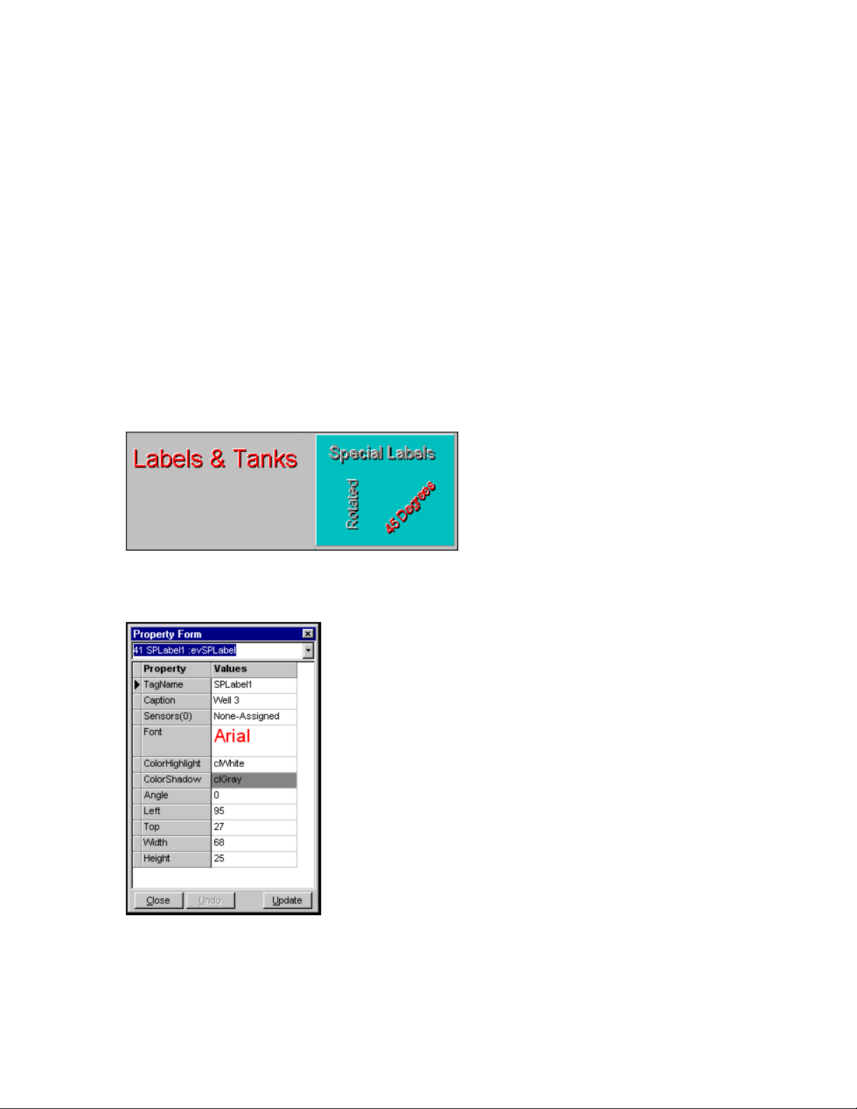
Special labels are used as form titles. Special labels are 3-dimension labels. This label can be
rotated also.
note: Global alarm buttons can be shown as text that can also be rotated. The global alarm
button doesn’t have to be assigned a sensor address. The global alarm button also has different
shapes you can use for display.
To add a special label to the current form, click on the Add Special Label button on the Displays
tab of the toolbar. Special labels are mainly for labeling screens and components. They have a
3-D appearance, and can be rotated. This makes them useful for creating attractive screens.
Special labels can be assigned a address to display data.
Special labels can be rotated and used as titles.
Special label property box
No Special TagName Properties
M-3834-0602 WMS-16STR WINDOWS GRAPHICAL SOFTWARE MANUAL.doc Page 57 of
57
Page 58

WMS-16STR Windows Graphical Page 58
Software Display Reference
M-3834-0602 WMS-16STR WINDOWS GRAPHICAL SOFTWARE MANUAL.doc Page 58 of
58
Page 59
WMS-16STR Windows Graphical Page 59
Software Display Reference
LED Indicator (Analog Display)
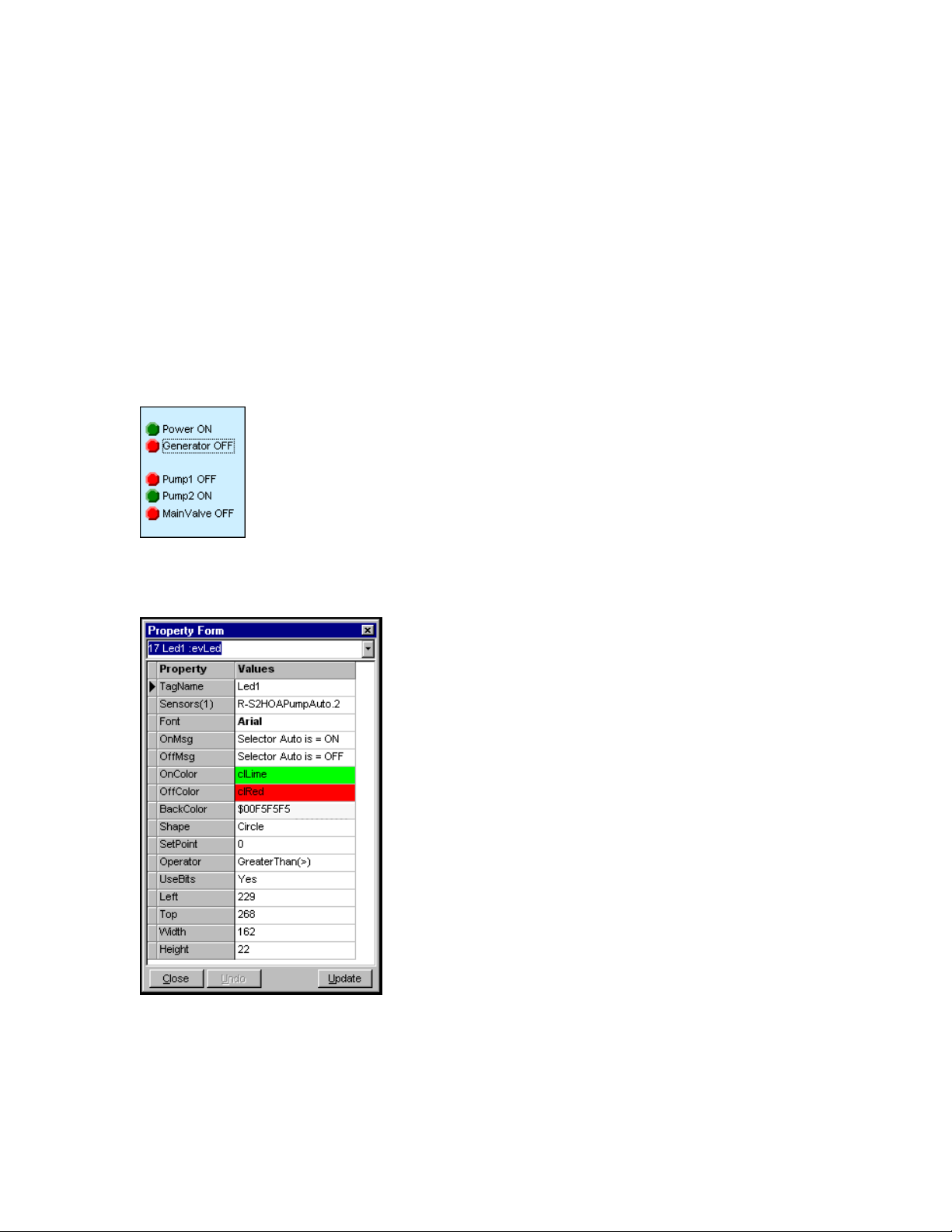
The LED component is used to show status messages when a bit changes. The LED changes
colors and the caption changes.
To add a status indicator to the current form, click on the Add Status Indicator Button on the
Displays tab of the toolbar. The status indicator is a component capable of displaying data values.
It shows the state of any bit in the system. Use it to display on, off, or fail conditions for tanks,
pumps, valves, or anything else. The LED can also change colors based on < <> > conditions.
Status indicator changes color and caption.
Status Indicator-LED property box
No Special TagName Properties
M-3834-0602 WMS-16STR WINDOWS GRAPHICAL SOFTWARE MANUAL.doc Page 59 of
59
Page 60

WMS-16STR Windows Graphical Page 60
Software Display Reference
M-3834-0602 WMS-16STR WINDOWS GRAPHICAL SOFTWARE MANUAL.doc Page 60 of
60
Page 61
WMS-16STR Windows Graphical Page 61
Software Display Reference
Rain Button (Analog Display)
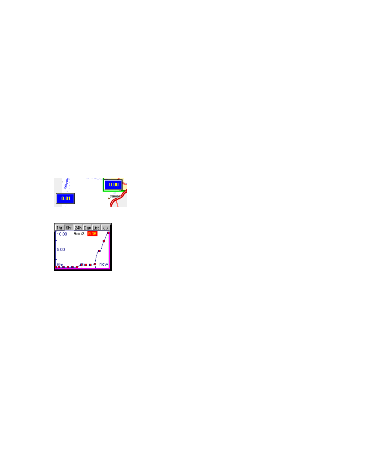
Use the rain component to show an analog value accumulation. The rain component shows a
running total accumulation change over time. The time intervals are fixed at 1 hour, 6 hours, 24
hours and each day for 30 days. Alarms can be enabled for these time periods. The WS16 time
should be close to your computer's time. The rain button calculates rain rates using the computer
clock. To get accurate rain rates, the computer needs to be on monitoring the WS16 sensors.
To add a rain button to the current form, click on the Add Rain Button on the display tab of the
toolbar. The rain button shows the current rain accumulation for 1 hour, 6 hour, 24 hours, or 30
days. Clicking on the rain button displays rain-graph summaries. The list is the memo display of
all the summaries. The rain graph is closed when editing and other forms are opened. The rain
initialization file name is RateRain1.evt.
Rain Buttons
Open the rain graphs by clicking on a rain button
Close the rain graph by clicking on the graph or X button
M-3834-0602 WMS-16STR WINDOWS GRAPHICAL SOFTWARE MANUAL.doc Page 61 of
61
Page 62
WMS-16STR Windows Graphical Page 62
Software Display Reference
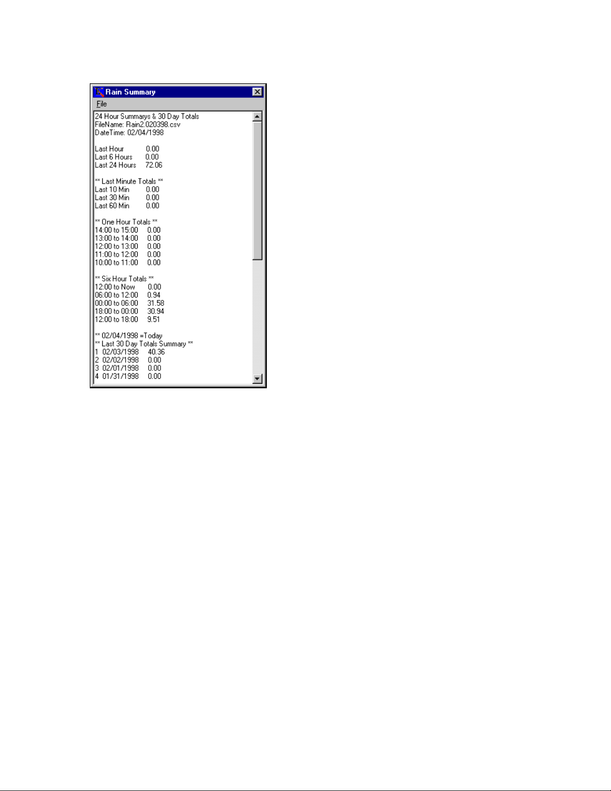
Rain list showing one hour, six hour, 24 hour and 30 rain totals
Print or save the memo, click File | Save or File | Print
Rain Alarms
The rain button can also be configured to activate alarms based on accumulation. You can set
low and high alarms for each time period (1 hour, 6 hours, & 24 hours). If the rain accumulation
exceeds any of these values and the alarm is enabled, a system alarm will be triggered. The
system alarm logs the alarm in the current and historical alarm log. You can configure the type of
alarm action needed (log, blink, show, sound, message).
The rollover is used for ALERT telemetry systems where the accumulator value rolls over when
counting up. If the value is –1, the roll over is ignored or disabled. ALERT systems use a roll over
value of 2047.
To reset the rain values to zero, select the ResetRate to yes and press update. You can not undo
a reset action. The next value received will be the starting accumulator value. Rain data received
is stored in rate files, in the data folder. The accumulative file is named Rate-Name.evt in the
project folder.
The multiplier (Mult.) property can be set to 0.03937, 0.01, or 1 to make engineering units.
M-3834-0602 WMS-16STR WINDOWS GRAPHICAL SOFTWARE MANUAL.doc Page 62 of
62
Page 63
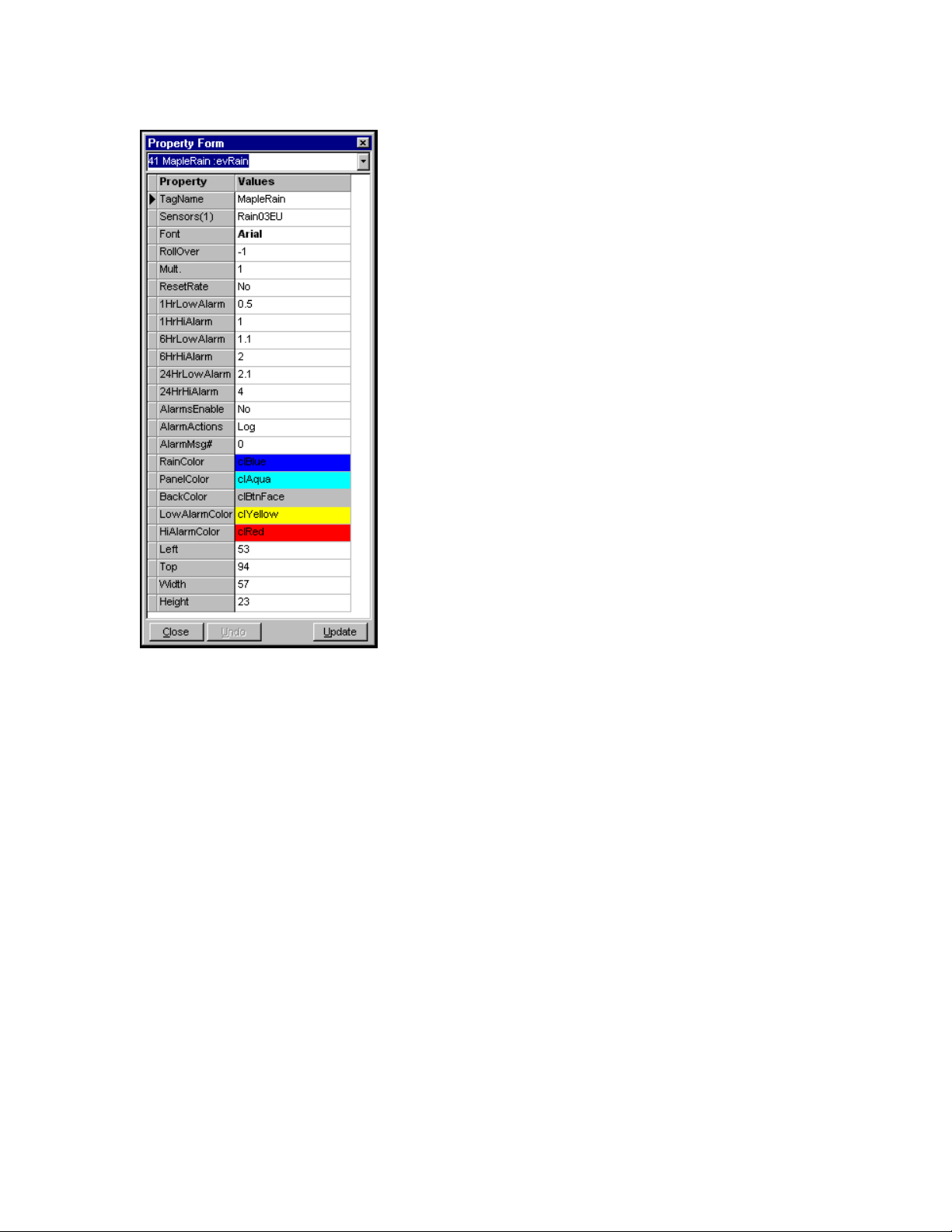
WMS-16STR Windows Graphical Page 63
Software Display Reference
Rain Button property screens
No Special TagName Properties.
M-3834-0602 WMS-16STR WINDOWS GRAPHICAL SOFTWARE MANUAL.doc Page 63 of
63
Page 64
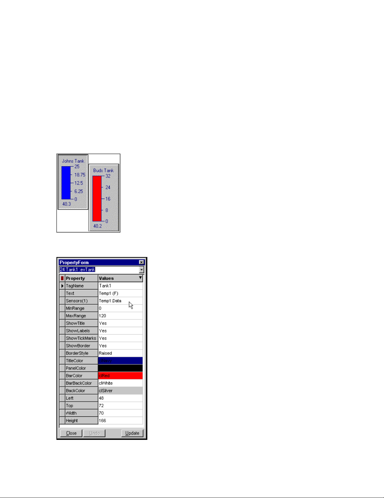
WMS-16STR Windows Graphical Page 64
Software Display Reference
Tank (Analog Display)
Tanks are visual displays of analog value changes. The tank shows the analog value as
a graphical bar chart as well as numerically.
To add a tank to the current form, click on the Add Tank Button on the display tab of the toolbar.
The tank component displays sensor data from a minimum to maximum value. The rising and
lowering of the tank bar indicates the level.
Tanks or bar charts can be displayed in different colors and borders.
Tank property box
M-3834-0602 WMS-16STR WINDOWS GRAPHICAL SOFTWARE MANUAL.doc Page 64 of
64
Page 65

WMS-16STR Windows Graphical Page 65
Software Display Reference
Tank Properties.
Title Color- the title color sets the color of the text on the tank, which displays the title.
Back Color- the back color determines the panel color on which the tank sits.
Tank Color- the tank color is the color of the stuff in the tank. In a water tank, the tank color is
the water. This is what raises and lowers indicating the level.
Tank Back Color- the tank back color is the color behind the tank color within the tank.
Show Title- when this is checked, the title will be shown, and otherwise it will be hidden
Show Labels- when this is checked, the numbers on the side of the tank will be shown, and
otherwise they will be hidden.
Show Tick Marks- show or hide the horizontal lines on the side of the tank with this checkbox.
Show Border- show or hide the border around the actual tank with this checkbox.
Border Style- the panel on which the tank sits can be nonexistent (None), Raised, or Lowered.
Raised will make the panel sit forward a bit, and lowered will make it sink into the form.
Max Value- each tank must have a maximum value to create its own scale. Set the maximum
level of the tank here.
Min Value- each tank must also have a minimum value. Set the minimum level of the tank here.
No special TagName properties.
M-3834-0602 WMS-16STR WINDOWS GRAPHICAL SOFTWARE MANUAL.doc Page 65 of
65
Page 66
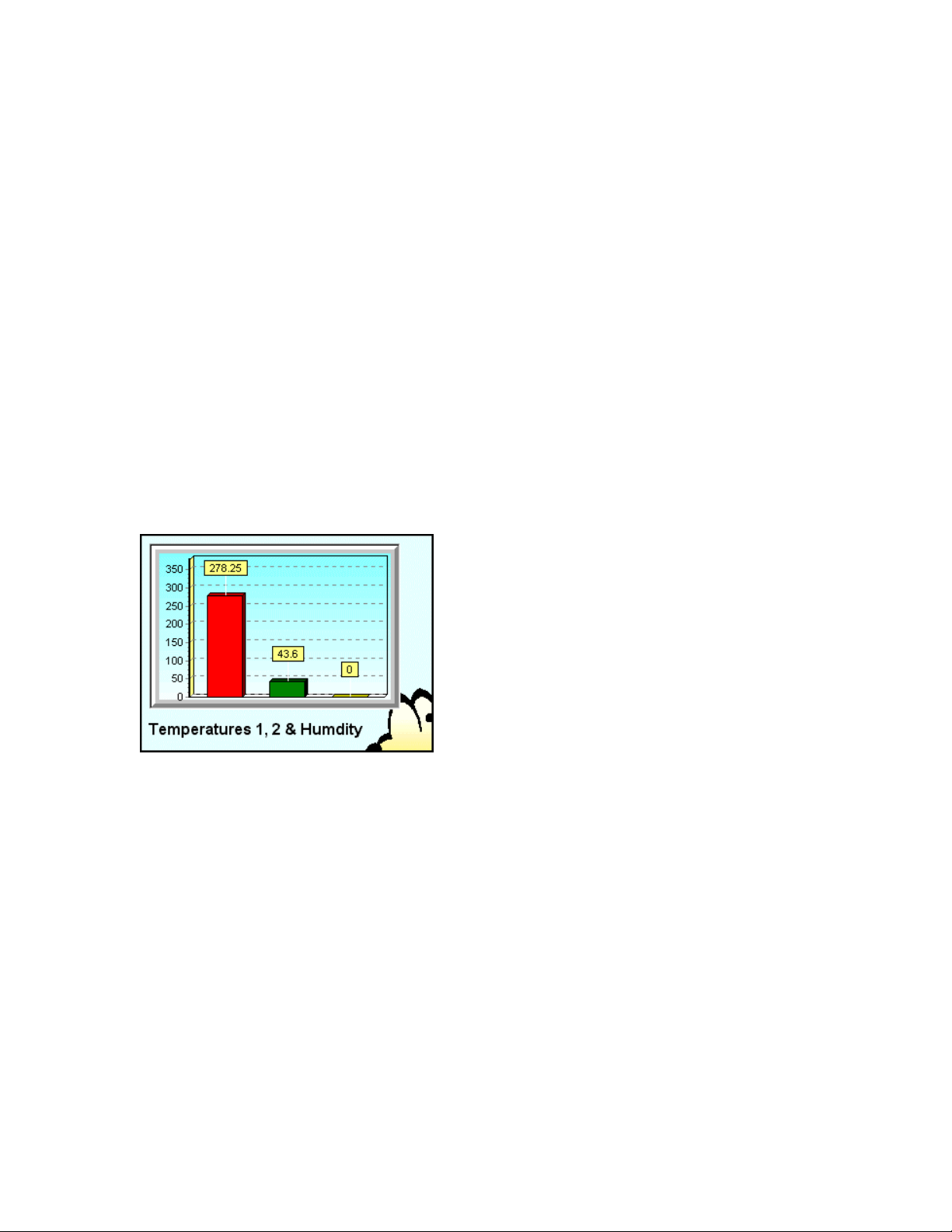
WMS-16STR Windows Graphical Page 66
Software Display Reference
Button Chart (Analog Display)
Button trend charts are used to display one or more analog values in a historical trend. This
component is really two charts. The first chart is the button. The second chart is the trend. You
must first configure the button chart properties to add sensors, etc. Then in the run mode click
the button to present the historical chart. A separate edit button allows you to configure the
settings for the trends.
To add a button chart to the current form, click the Add Button Chart in the Displays tab of the
toolbar. Double click the component and add "like" sensors to the button chart properties. The
sensors' data values will be shown on the button and in the trend.
Note: The button chart has a time step property that adds a new data point to the trend at that
time step. The trend also updates when the data value of any sensor changes. This way
changes in sensor values are recorded in the trends. Maximum and minimum values will not be
missed.
The button chart shows the last value received for each sensor.
Click on button to view trend.
Button Chart Properties (On the button)
The button chart and trend chart have separate property setting. The button chart has a standard
property dialog where you define the sensors to plot, the number of points to plot and the look of
button. The trend chart properties are set by viewing the trend and then clicking on the red edit
button.
1. Button Chart
The button chart shows the last received value for each sensor. Click the button to show the
historical trend. If you right click the button chart in the run mode, you will be presented a chart
property dialog that allows you to configure the look of the button chart. This dialog is the same at
the trend chart property dialog.
M-3834-0602 WMS-16STR WINDOWS GRAPHICAL SOFTWARE MANUAL.doc Page 66 of
66
Page 67
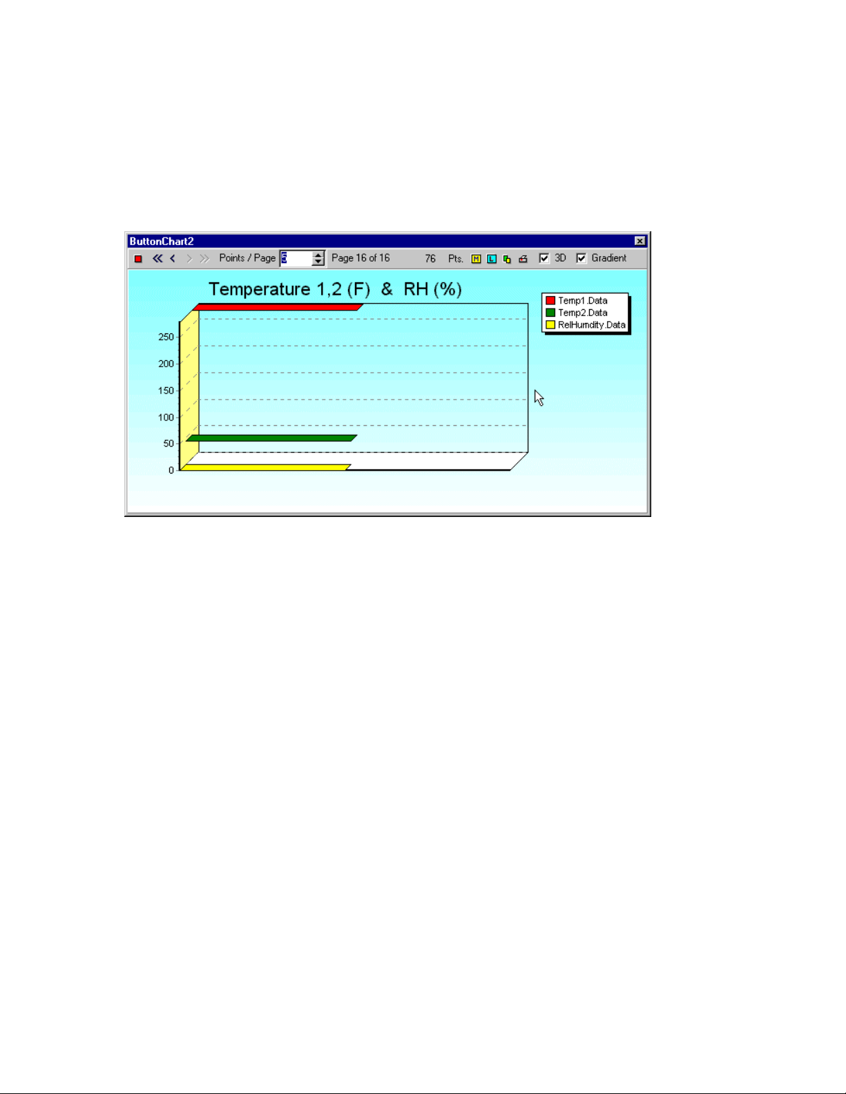
WMS-16STR Windows Graphical Page 67
Software Display Reference
2. Trend Chart Properties
The trend chart also has separate properties that can be set. Click on the red edit button to
change the look of the trend chart. See the trend chart dialog options below.
The red edit button allows you to configure the look of the trends.
The chart trends each sensor defined by the button chart. The toolbar at the top is for editing the chart trends.
Trend Chart Toolbar
Edit Button (Red Square)
Click this button to change the properties of the trend chart. Below are several screens showing
all the properties you can set for each trend.
Navigator Buttons
Click on the navigation buttons to go back in time or move forward. The double arrows go to the
first or last page of data.
Points / Page Selection
This is the number of points plotted on the trend. If you enter a zero (0), the chart plots all the
points. As you change the number of points, the chart is updated.
Mark Button
M-3834-0602 WMS-16STR WINDOWS GRAPHICAL SOFTWARE MANUAL.doc Page 67 of
67
Page 68

WMS-16STR Windows Graphical Page 68
Software Display Reference
The mark button shows a yellow box with the data value for each point on the chart. If more than
one series is being plotted a dialog box will be presented for you to specify the data series you
want to mark.
Legend Button
This is the show chart legend toggle. The chart legend will be displayed showing a color symbol
and name of the sensor being plotted.
Copy Button
The copy button copies the current chart to the clipboard. You can paste the chart into the report
editor or into a graphics program like paint.
Print Button
The print button presents a print preview dialog box so you can select how you want the chart to
print. You can cancel the print or print it to your printer.
3D Checkbox
The chart can show data in three dimensions or in two dimensions. Unchecked is twodimensional, checked is three-dimensional.
Gradient Checkbox
The chart's background is either a solid color or gradient color. The gradient checkbox allows
you to toggle this option on and off. The gradient start and end colors can be selected from the
chart property dialog.
Setting up the Button Chart
To modify the properties of any component, double click it, and the Property Form will open. The
property form shows the properties of the button. These properties should be set first before you
configure the trend properties.
The ChartName property should be a unique name. This name is used when storing the trend
charts properties, data and position. If two charts have the same name, one chart will overwrite
another chart's data. Use chart names that are meaningful.
M-3834-0602 WMS-16STR WINDOWS GRAPHICAL SOFTWARE MANUAL.doc Page 68 of
68
Page 69
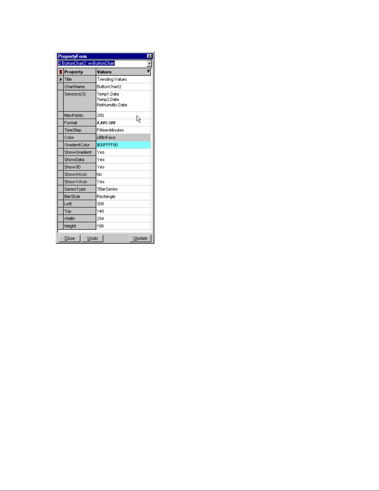
WMS-16STR Windows Graphical Page 69
Software Display Reference
Button chart properties
These are the Button Chart Properties . These properties should be set first. Then change the
trend properties. Change a property and click the update button to view your changes. You can
always click the undo button to go back to the original components properties.
Trend Chart Property Dialogs
There are many properties that you will never set. The ones that are used the most are shown in
the Axis tab, Titles tab, Paging tab and 3D tab. All the tabs are show below for reference.
M-3834-0602 WMS-16STR WINDOWS GRAPHICAL SOFTWARE MANUAL.doc Page 69 of
69
Page 70
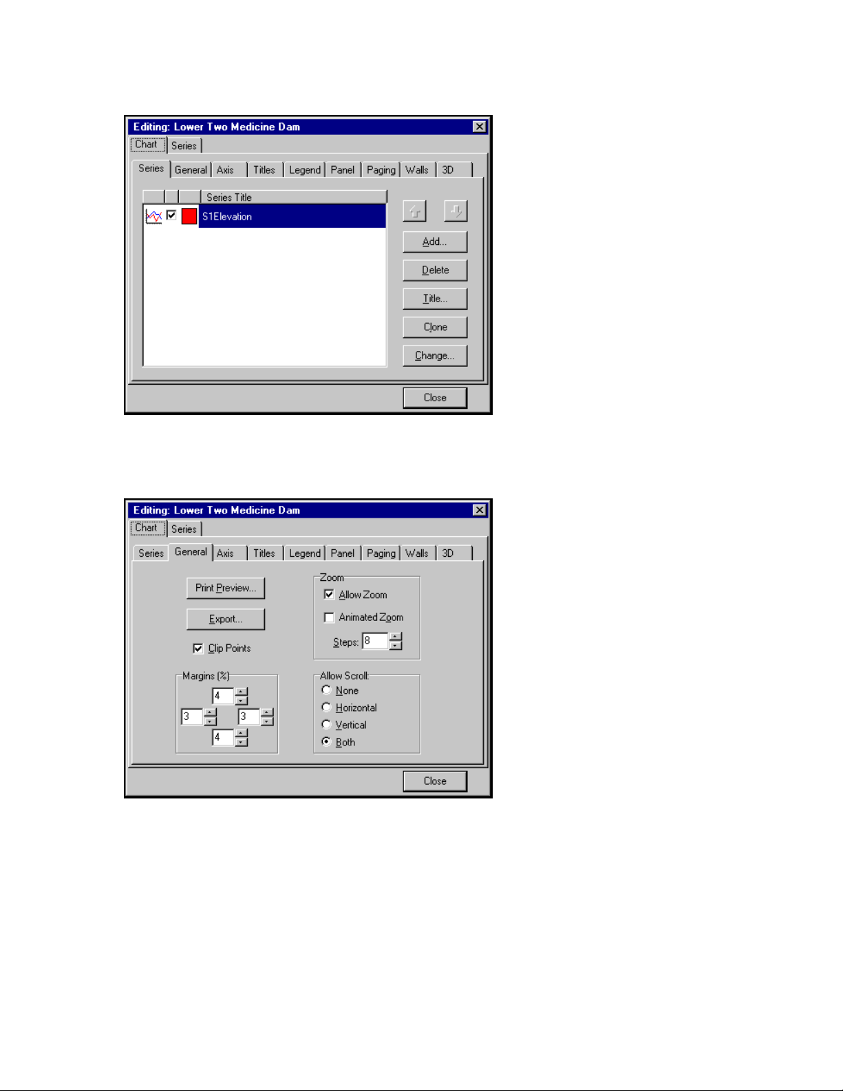
WMS-16STR Windows Graphical Page 70
Software Display Reference
The chart series name is show here. The type of data series is shown by small graphic
icon to the left. The check mark enables the trend. The square shows the color of the series.
The General tab allows you to export the chart, print preview it, set the zoom properties
and scroll properties.
M-3834-0602 WMS-16STR WINDOWS GRAPHICAL SOFTWARE MANUAL.doc Page 70 of
70
Page 71
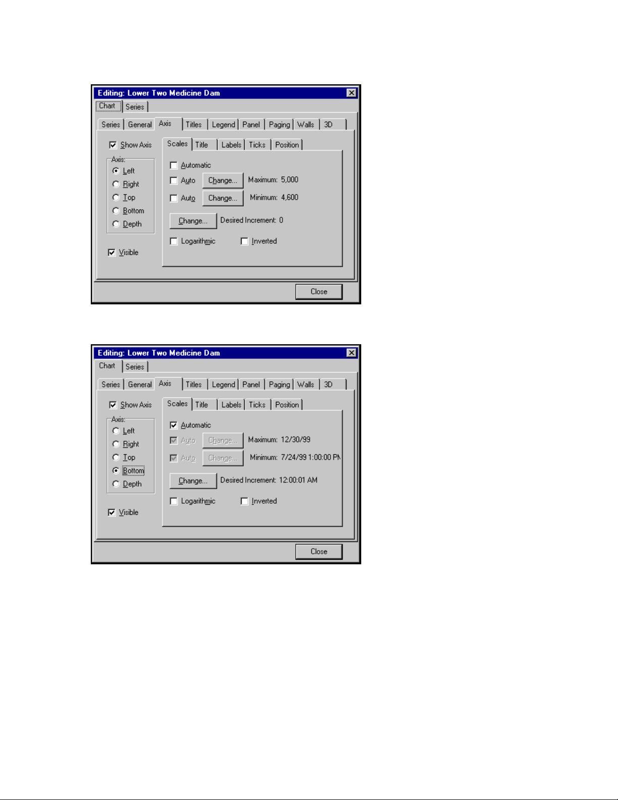
WMS-16STR Windows Graphical Page 71
Software Display Reference
The Axis tab allows you to set the left axis minimum and maximum values.
Use these to see the range desired.
The bottom Axis should be set to automatic. You can specify a minimum and maximum range
for custom charts. Data not in that range will not be shown. If your trend is not showing the
correct time, be sure to set the chart to automatic.
M-3834-0602 WMS-16STR WINDOWS GRAPHICAL SOFTWARE MANUAL.doc Page 71 of
71
Page 72
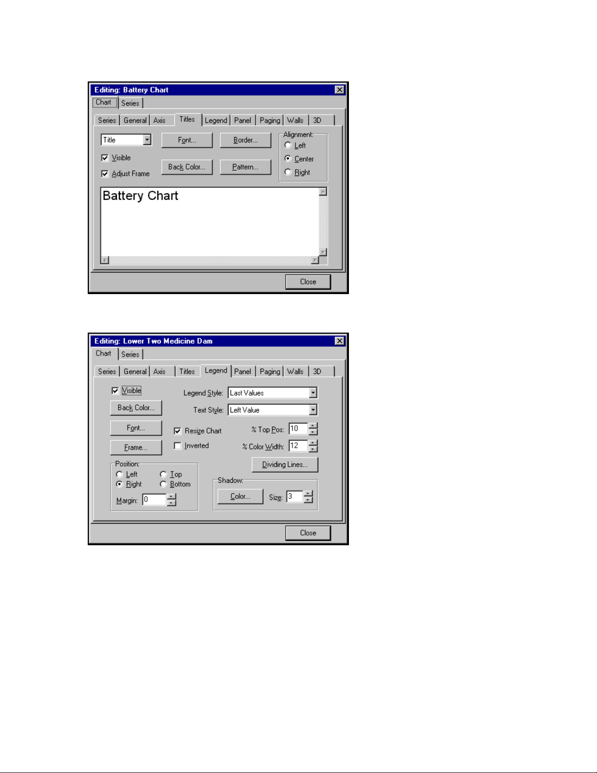
WMS-16STR Windows Graphical Page 72
Software Display Reference
The Titles tab allows you to set the title for the trend. Change or add the text to help define
the sensors being trended.
Show the legend, position the legend and define what shows in the legend.
M-3834-0602 WMS-16STR WINDOWS GRAPHICAL SOFTWARE MANUAL.doc Page 72 of
72
Page 73
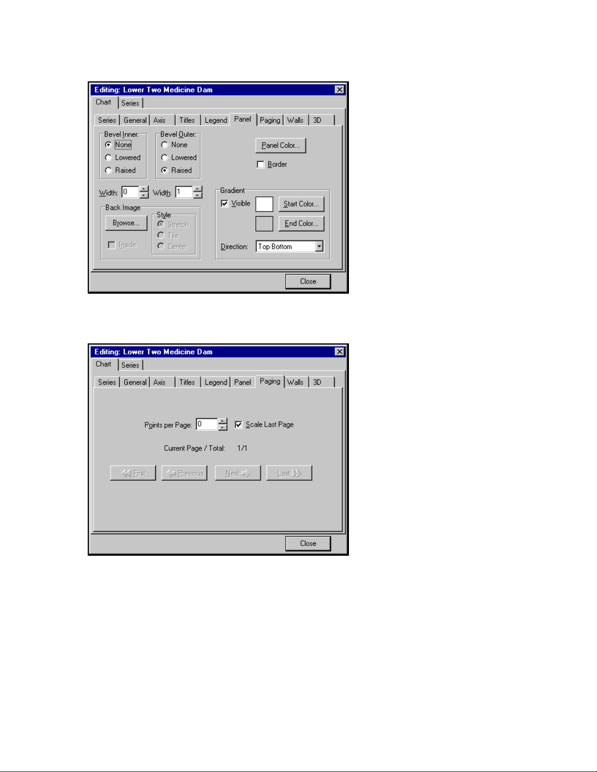
WMS-16STR Windows Graphical Page 73
Software Display Reference
The Panel tab allows you to set the gradient color of the back panel.
The Paging tab allows you to set the number of points per page and to scale the last page.
M-3834-0602 WMS-16STR WINDOWS GRAPHICAL SOFTWARE MANUAL.doc Page 73 of
73
Page 74
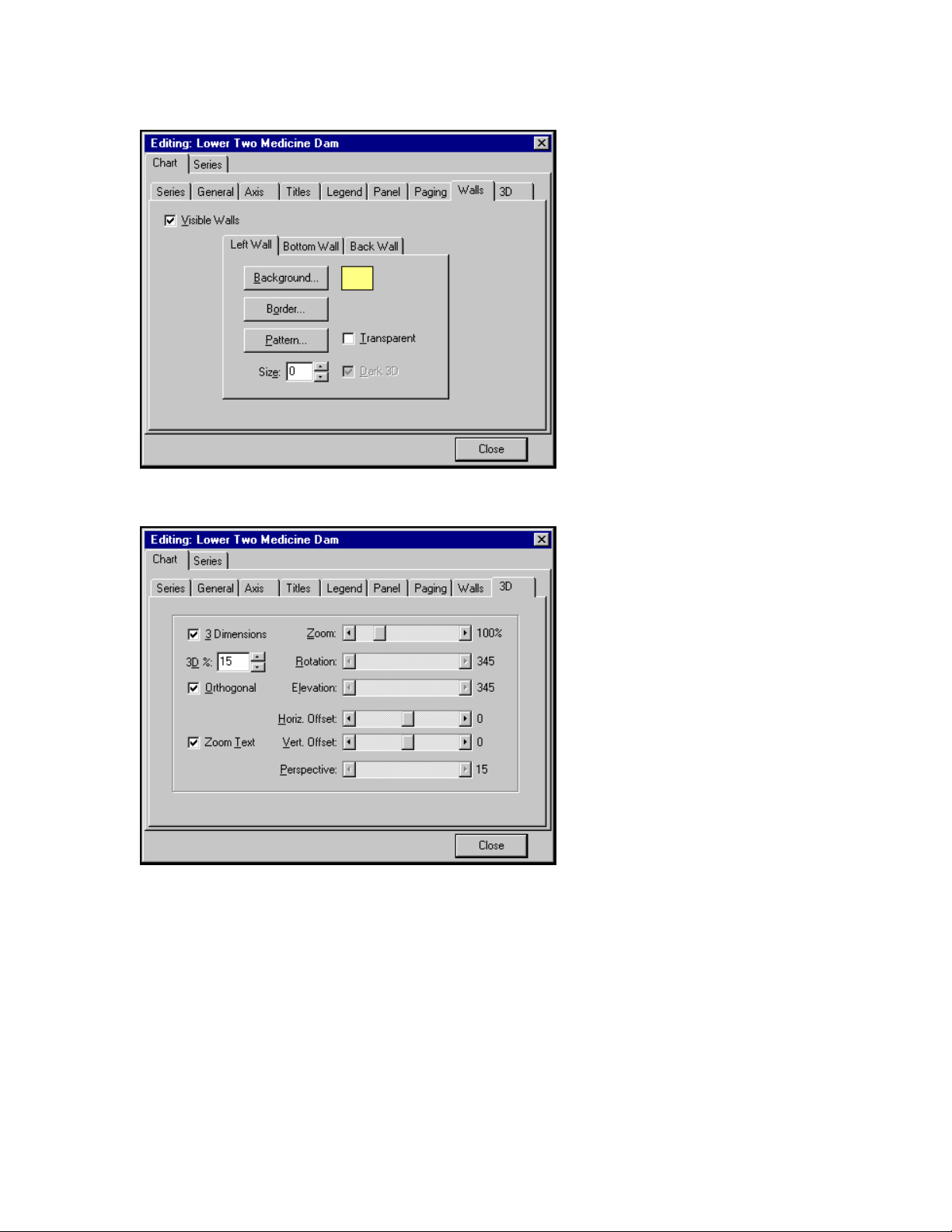
WMS-16STR Windows Graphical Page 74
Software Display Reference
The Walls tab allows you set the left wall, bottom wall and back wall of the trend.
The 3D tab allows you to set the three-dimensional properties of the trend.
M-3834-0602 WMS-16STR WINDOWS GRAPHICAL SOFTWARE MANUAL.doc Page 74 of
74
Page 75
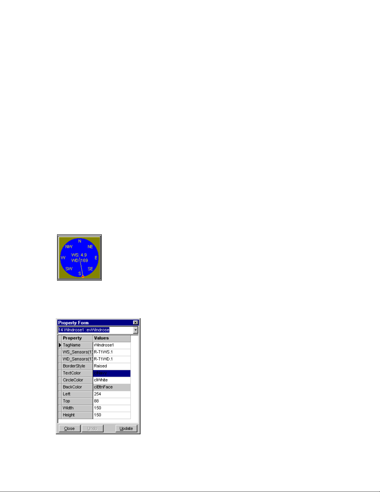
WMS-16STR Windows Graphical Page 75
Software Display Reference
Wind Speed & Direction (Analog Display)
Use a Wind component to display wind speed and direction graphically. The wind data and
direction data are separate sensors. Size the component according to your needs.
To add a wind speed and direction component to the current form, click on the Add Windrose
button in the display tab of the toolbar. Wind speed is normally 0 to 100 mph and wind direction is
0 to 360 degrees.
N = 0 or 360 degrees
E = 90 degrees
S = 180 degrees
W = 270 degrees
Two Windrose components are shown. Each component combines two
analog measurements (Wind Speed and Direction.).
Windrose Properties
M-3834-0602 WMS-16STR WINDOWS GRAPHICAL SOFTWARE MANUAL.doc Page 75 of
75
Page 76

WMS-16STR Windows Graphical Page 76
Software Display Reference
There are no special TagName properties.
M-3834-0602 WMS-16STR WINDOWS GRAPHICAL SOFTWARE MANUAL.doc Page 76 of
76
Page 77
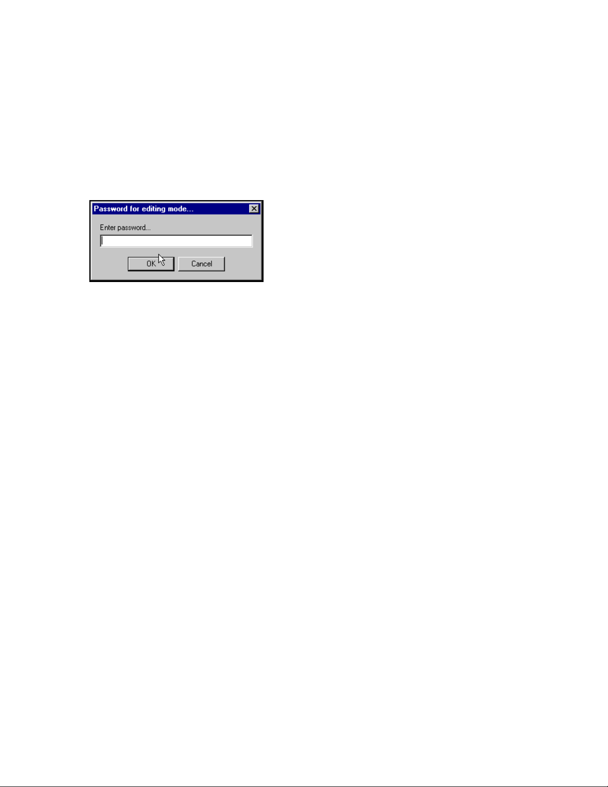
WMS-16STR Windows Graphical Page 77
Software Display Reference
Password
The Password allows the current user to go into the edit mode. Once the correct password has
been entered the user can edit screens and communication parameters.
Enter password dialog
M-3834-0602 WMS-16STR WINDOWS GRAPHICAL SOFTWARE MANUAL.doc Page 77 of
77
Page 78
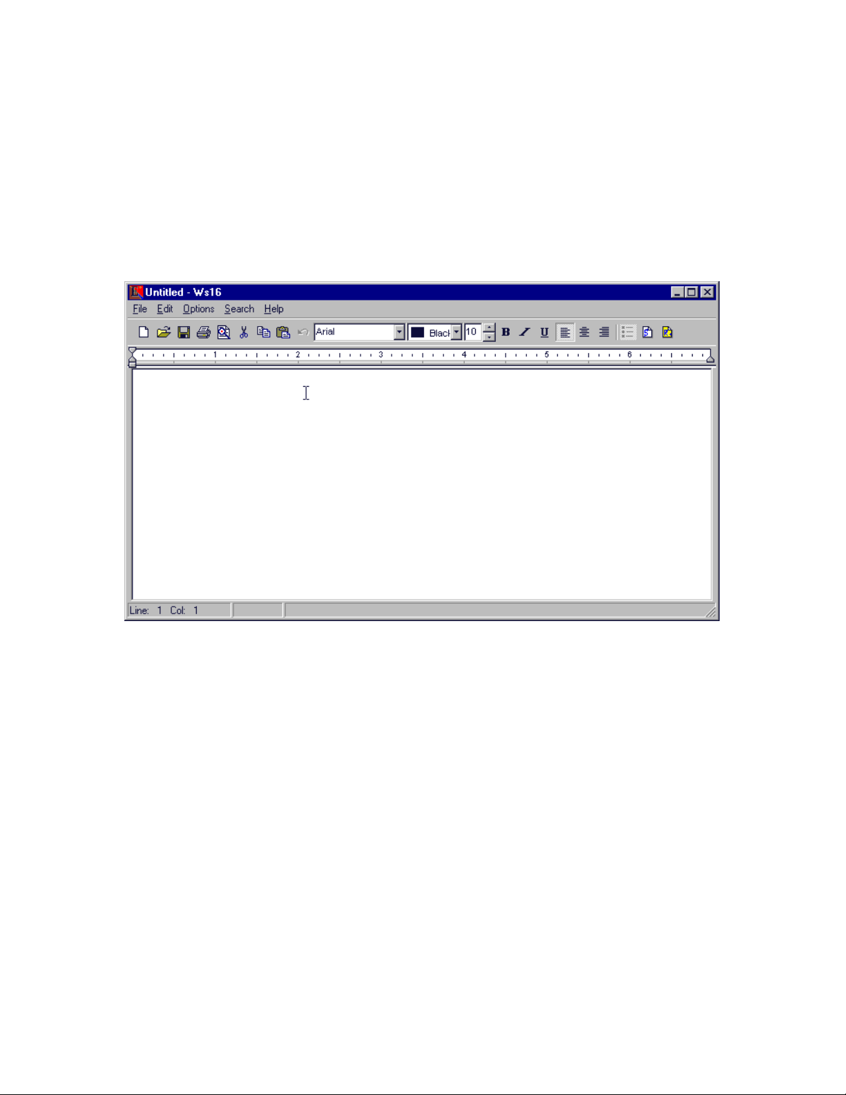
WMS-16STR Windows Graphical Page 78
Software Display Reference
REPORT EDITOR
Reports are generated by use of the report editor. Form reports create a bitmap of the active
form and place it in the report editor for viewing and printing. Maximums, minimums, averages
and data from your sensors can be printed out in a professional looking report.
Report editor with no files loaded.
GENERAL REPORT INSTRUCTIONS
M-3834-0602 WMS-16STR WINDOWS GRAPHICAL SOFTWARE MANUAL.doc Page 78 of
78
Page 79
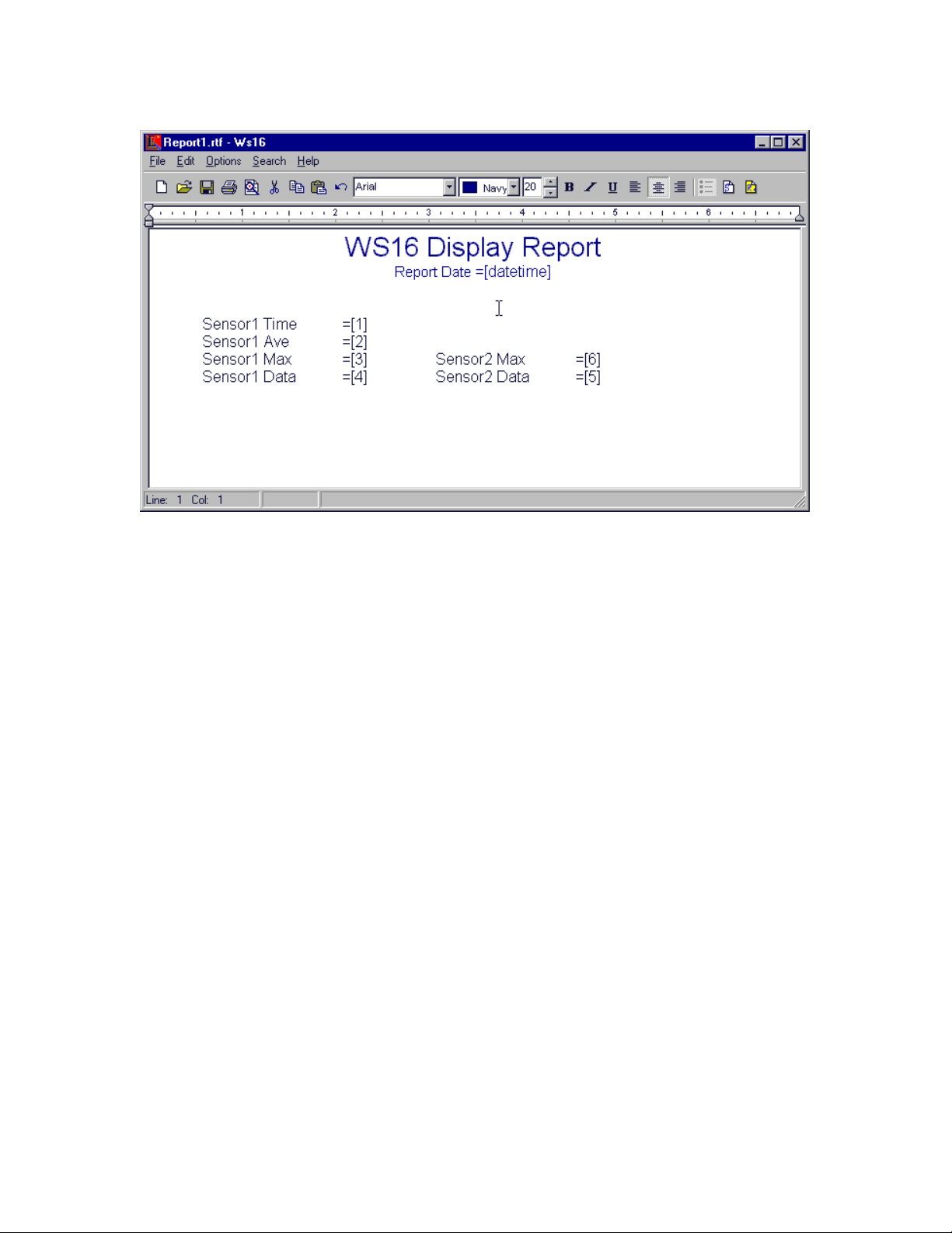
WMS-16STR Windows Graphical Page 79
Software Display Reference
Adding data to your reports
To make reports you type into the editor the details of the report. Enter the titles, subtitles, and
text as needed. Format the titles and text by using color and changing fonts, font styles. Use built
in commands for dates (=[date], =[time] or =[datetime]) and then enter placeholders for data
(=[1]. =[2], =[3]). Set your tabs for each row in the report. Tabs will help to line up rows of data at
the same point in the report.
You can mix and match text with data placeholders. This way you can identify the data with the
text.
Set tabs by clicking in the ruler area. Remove tabs by selecting the tab and dragging off the ruler.
Move the tabs by selecting the tab and drag.
After you have entered some placeholders for data, select the add sensors button on the right and
select the sensors you want to use for the data. After you have made your sensor selection,
press the run report button and the report will be produced.
You can not edit the finished report directly. You need to go back to the editor and edit it, and
then run your report again. To go back to the editor, click the run button again.
Be sure to save the report with an *.rtf extension. When data has been entered into the sensor
list a second file is saved with the sensor information, margins, headers and form size. When the
scheduler prints the report, this information is required to make the report look right.
You can print and preview both the setup report and the report itself. Just click on the print or
preview buttons. You can also save the data report separately if you need to keep a copy of it.
You can always regenerate the report as long as the data is in the database. Real time data will
change if you are pulling the current data from the grids.
M-3834-0602 WMS-16STR WINDOWS GRAPHICAL SOFTWARE MANUAL.doc Page 79 of
79
Page 80
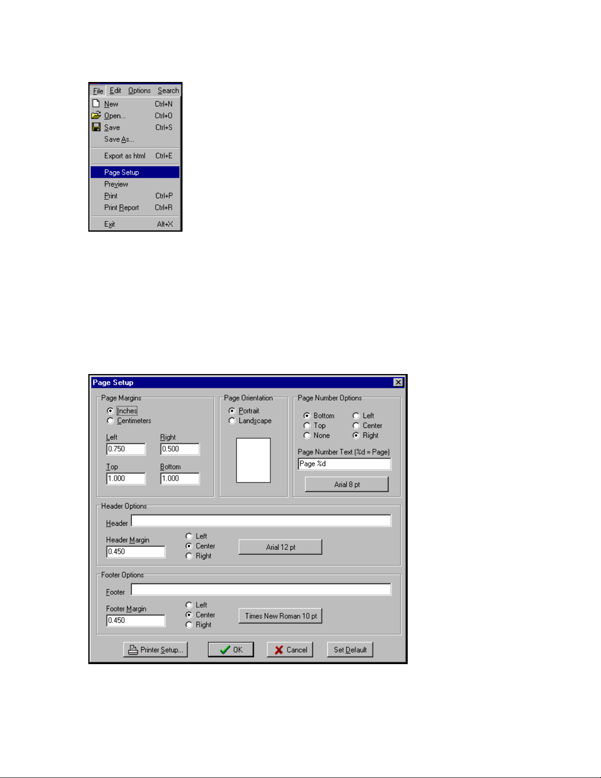
WMS-16STR Windows Graphical Page 80
Software Display Reference
File Menu: Open and save files, preview, print or print report if sensors are assigned
These are standard word processing commands. Use the print report command if you have data
placeholders and have selected sensors for your data. You may want to run the report first to see
what it looks like. Press the run report button on the right of the editor to run the report.
Page Setup
Press the Page Setup menu item to set the page formatting options.
Page Setup allow you to set margins, headers, footers and positions. These settings are saved with the report.
M-3834-0602 WMS-16STR WINDOWS GRAPHICAL SOFTWARE MANUAL.doc Page 80 of
80
Page 81
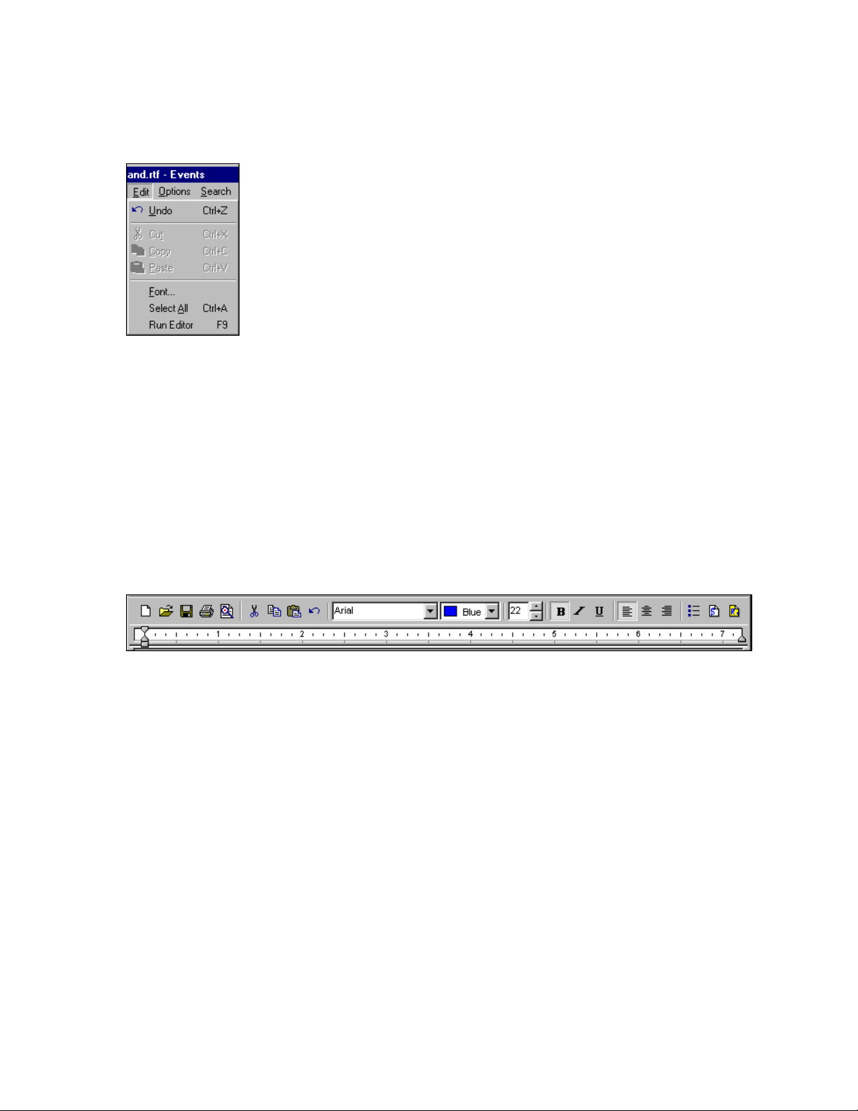
WMS-16STR Windows Graphical Page 81
Software Display Reference
Report Edit Menu
Edit Menu: Standard editing function plus run editor.
The edit menu allows you to cut, copy, paste, select all and change font. You must select some
text first before you can use these commands. The Run Editor command executes the report by
getting the data and showing the finished report. Go back the editor by clicking the same option
again.
Report Tools
Report Toolbar and ruler. The two buttons on the right allow you to select sensors for your report and to run the report.
You can view what each button does by placing the cursor over the button. A hint will be shown
with the action of the button. The toolbar buttons and windows are as follows:
New file, open file, save file, print file, preview file, cut, copy, paste, undo,
select fonts, font colors, font size,
font styles [bold, italicize, underline], align left, align center, align right, add bullets,
add sensors, run report.
ADDING DATA PLACEHOLDERS
M-3834-0602 WMS-16STR WINDOWS GRAPHICAL SOFTWARE MANUAL.doc Page 81 of
81
Page 82
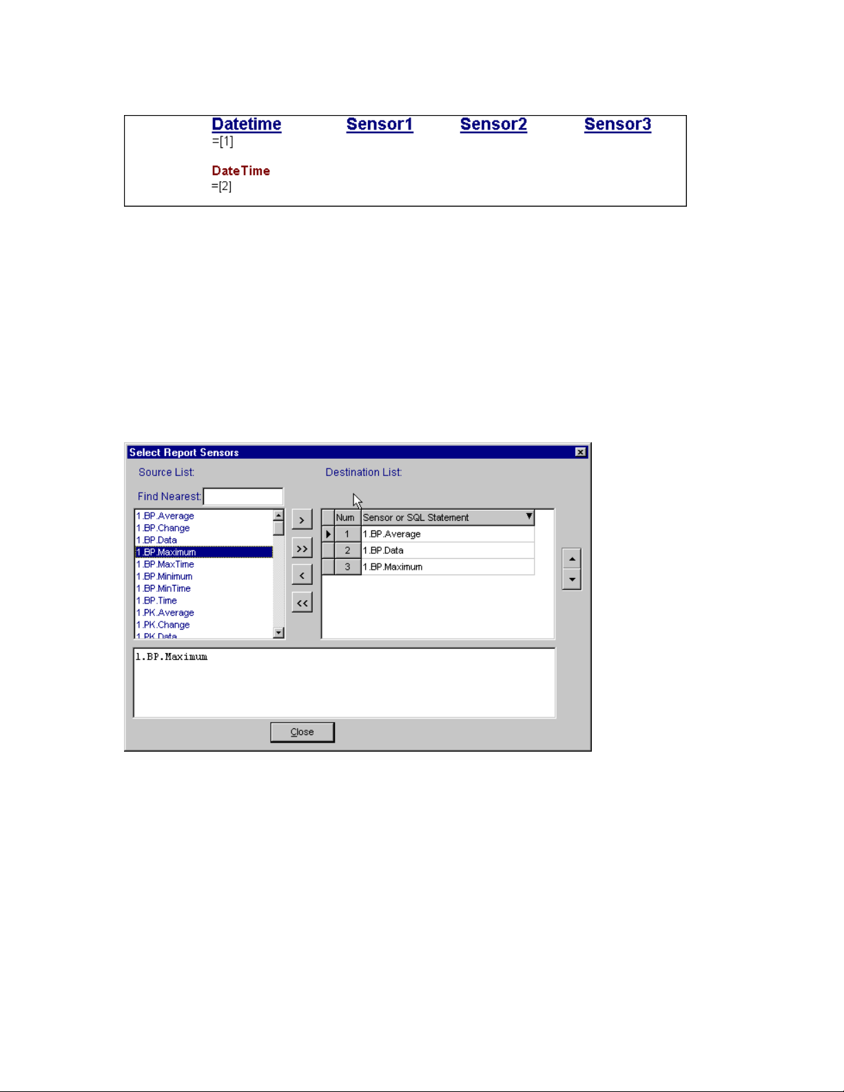
WMS-16STR Windows Graphical Page 82
Software Display Reference
Enter =[1] is the first sensor in the report. Sensors are defined
from any of the defined sensors in the setup grids and file girds.
REPORT FUNCTIONS ENTERED DIRECTLY
Report functions
=[date] =[time] =[datetime] =[day]
=[week] =[month] =[year]
Selecting sensors from the source list. The distination list is used for the report.
Add and remove sensors from source list. The destination list becomes your report list. You can
move sensors up and down in the list once it is entered into the destination list. The number of
the destination list relates directly to data placeholder number in the report.
EXAMPLE OF A SMALL REPORT
M-3834-0602 WMS-16STR WINDOWS GRAPHICAL SOFTWARE MANUAL.doc Page 82 of
82
Page 83
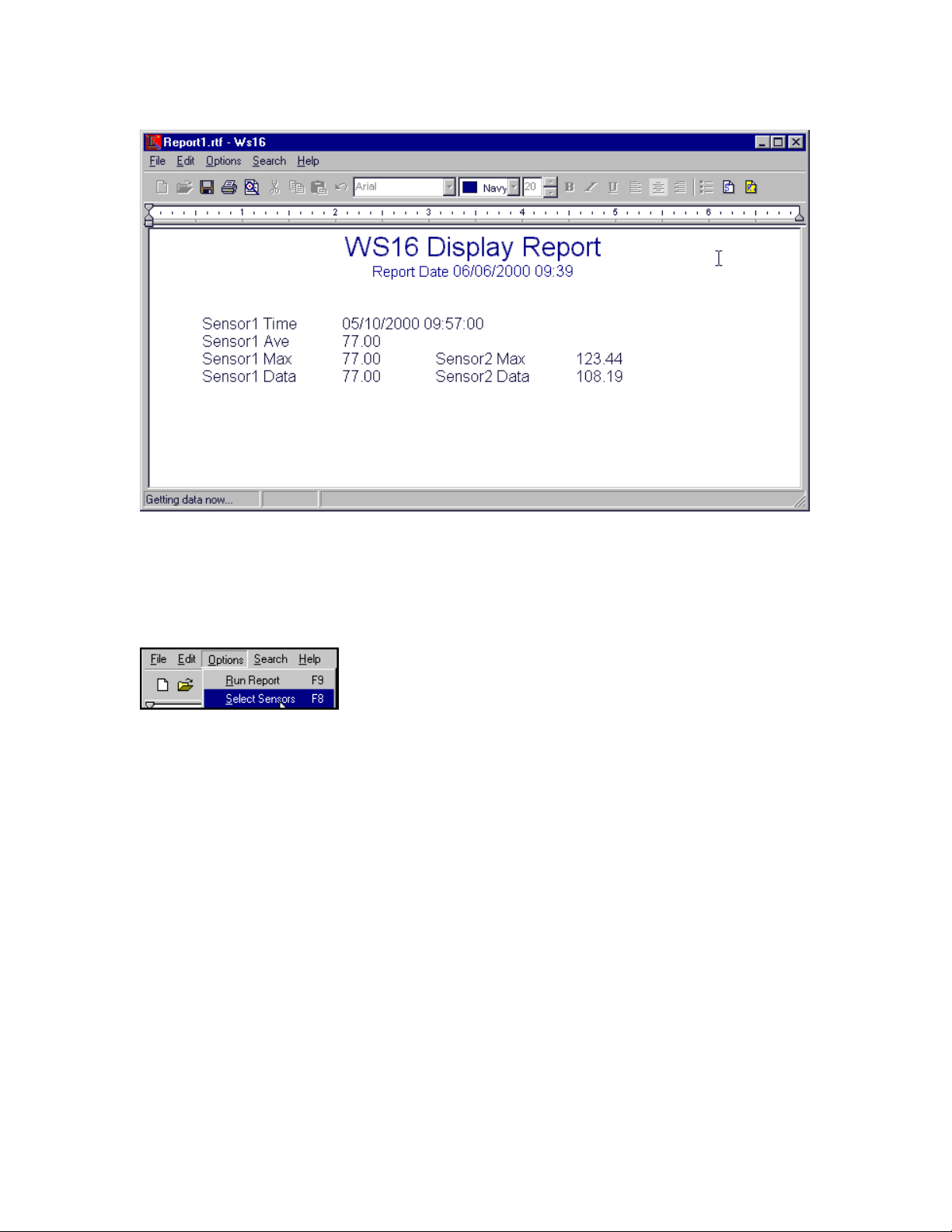
WMS-16STR Windows Graphical Page 83
Software Display Reference
Set your report with the look you want by using standard editing commands. Assign a sensor to each of the =[number],
and the values will be inserted into the report when it is run.
Options Menu
Report options: Run report or select sensors.
PRINT PREVIEW
M-3834-0602 WMS-16STR WINDOWS GRAPHICAL SOFTWARE MANUAL.doc Page 83 of
83
Page 84
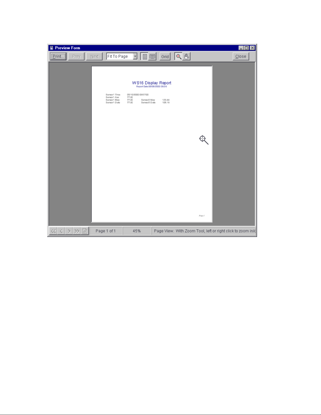
WMS-16STR Windows Graphical Page 84
Software Display Reference
Report preview: Select preview to see how your report will look printed.
Print the report from here by selecting the print button. You can print all pages or select the pages
you want from the print dialog that pops up.
Main Initialization File (WS16.ini)
The main initialization file is used to remember the main form screen location and which project
to open. You can manually change the Project Folder by editing this file. Just rename the
ProjectDir = New project location.
New Project Name must be a sub folder in the WS16 folder and it should contain a Project
initialization File with the same name as the folder (ie. NewProjectName.INI).
M-3834-0602 WMS-16STR WINDOWS GRAPHICAL SOFTWARE MANUAL.doc Page 84 of
84
Page 85

WMS-16STR Windows Graphical Page 85
Software Display Reference
WS16.INI
[ProjectDir]
ProjectDir=C:\program files\omega\Weather\
Project Initialization File
The project initialization file stores information about the project being opened. A typical example
is shown below. The main initialization file references the project initialization file.
The project initialization file can be modified to open only the forms you select. If you modify this
file and add forms to your project, the files added must be in the project directory with a .ffr
extension. The added forms must have been created by WS16.
Note: The project initialization file may reference many forms but only have a form count of 2.
The Count = number determines how many form files are opened. If the Count is 0, then no files
will be opened. The forms are opened starting with 0, then 1, etc.
Weather.INI
[PropertyForm]
Left=323
Top=91
Width=235
Height=437
[MainForm]
Left=185
Top=30
Width=687
Height=549
[FormTabs]
TabsVisible=1
Position=0
FontSize=8
Height=19
FontName=Arial
FontColor=clNavy
FontStyle=0
Format=1
[TimePanel]
FontSize=10
FontName=SF Sans Serif
FontStyle=2
FontColor=clNavy
BackColor=$0080FFFF
M-3834-0602 WMS-16STR WINDOWS GRAPHICAL SOFTWARE MANUAL.doc Page 85 of
85
Page 86

WMS-16STR Windows Graphical Page 86
Software Display Reference
[FormCount]
Count=4
[ListForm]
Left=526
Top=86
Width=200
Height=366
[ComSet]
Parsing=1
Opened=isOpen
ComSet=Com1,9600,8,1,None
Xmodem=RX2.txt
PhoneSet=Com2,14400,8,1,None
PhoneNum=1,2033591660
PhoneLabel=Omega: 1,2033591660
LoggerNum=1
Logged=Log1.txt
[SetupForm]
Left=65
Top=176
Width=686
Height=325
[ReportForm]
Left=121
Top=76
Width=689
Height=392
[ColorForm]
Left=403
Top=125
Width=288
Height=228
[TermForm]
Left=46
Top=265
Width=795
Height=357
[Files]
FileName=Omega.txt
FileDir=C:\Program Files\Delphi5\Omega2\Demo\Data\
Color=clInfoBk
FontName=Courier New
FontSize=9
FontColor=clBlack
FontStyle=0
Left=36
Top=363
M-3834-0602 WMS-16STR WINDOWS GRAPHICAL SOFTWARE MANUAL.doc Page 86 of
86
Page 87

WMS-16STR Windows Graphical Page 87
Software Display Reference
Width=751
Height=299
[Terminal]
PhoneCt=1
SendInit=0
ModemUseCTS=0
ModemUseDTR=0
ModemUseXOn=0
UseCTS=0
UseDTR=0
UseXOn=0
ComSet=COM1,19200,8,1,None,
Opened=isOpened
PhoneSet=COM2,19200,8,1,None,
Initialization=ATE1Q0
PhoneNum=12033591660
XmodemName=Xmodem.txt
R6FileName=
R6Dir=
Name=Omega
Color=clWhite
FontName=Courier New
FontSize=9
FontColor=clBlack
FontStyle=0
Left=45
Top=62
Width=680
Height=566
Parsing=0
PhoneList0=1,Omega,12033591660
[ParsingPref]
ResetAll=1
ResetMaxMin=0
ResetChange=0
ResetData=0
ResetRain=1
ResetTrends=1
[ChildForms]
3=Start.ffr
2=Summary.ffr
1=Trends.ffr
0=Overview.ffr
M-3834-0602 WMS-16STR WINDOWS GRAPHICAL SOFTWARE MANUAL.doc Page 87 of
87
Page 88
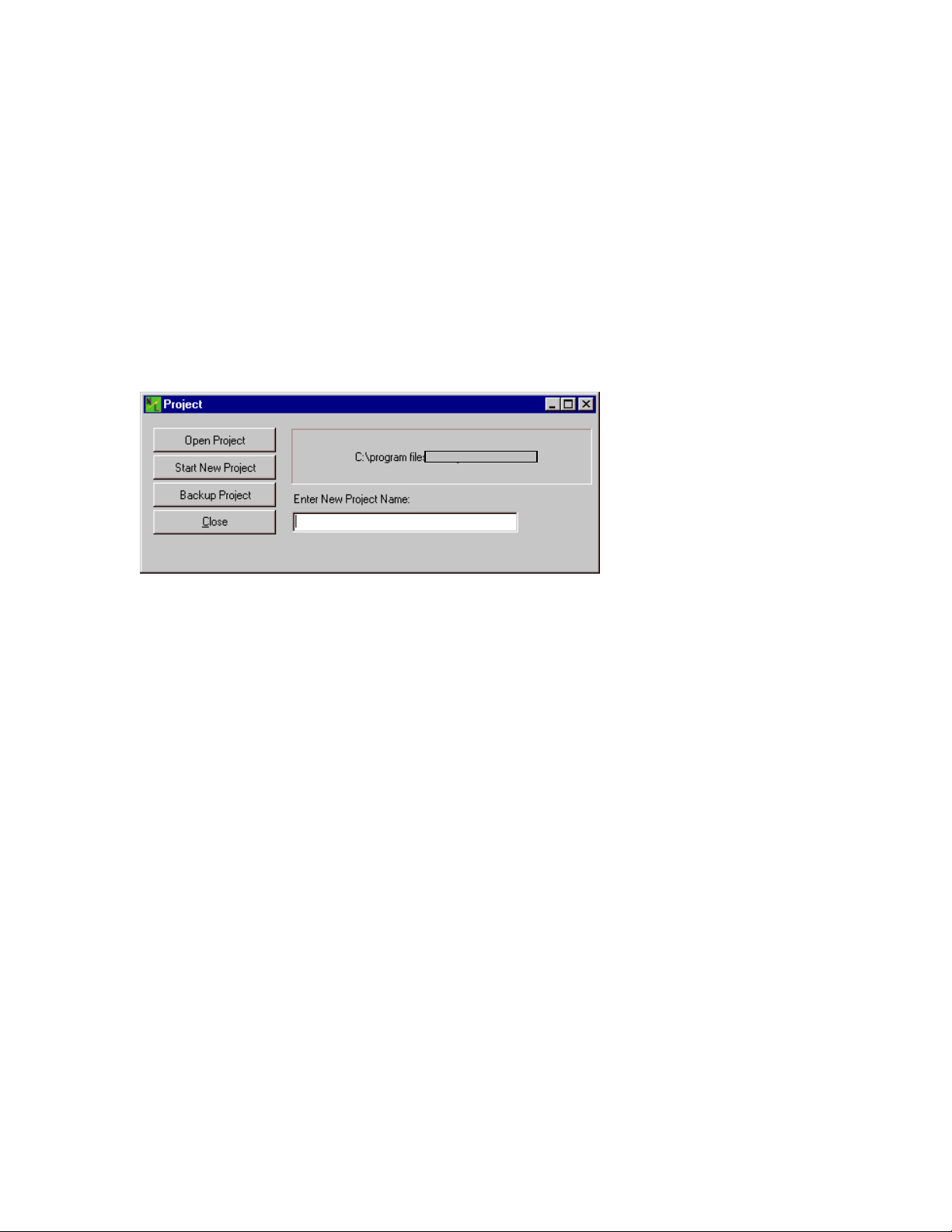
WMS-16STR Windows Graphical Page 88
Software Display Reference
PROJECTS
The Project menu item allows you to backup your current project to a new directory, open a new
project, or open existing project. If you backup or open a new project, you must enter a name in
the New Project Folder edit box.
If you open an existing project, a dialog box will open which allows you to select which project to
open. Select an existing project initialization file in the WS16 directory. Don't select your current
project or the WS16.ini file (a dialog box will ask you to select another project).
Open an existing project, start a new project or backup your existing project
Open Existing Project
To open an existing project, you select the menu item File | Project. Click on the Open Project
button. A dialog box will be shown which is asking you to select a project initialization file. This
project initialization file will be in a previously created project folder.
If you try to open the WS16.ini or the current project initialization file, you will be asked to select
another file. The project folder must be in a sub directory of the WS16 folder.
Note: the current project will saved automatically when a new project is opened.
Create New Project
Create a new project command is found by selecting the File | Project menu item.
The Project menu item creates a new project. Enter a new project name in the edit box. This
becomes your folder and initialization file name. Click on the Start New Project button and you will
be asked if you want to close this project and start a new project. Click OK and a new project will
be started.
Note: The current project will be saved when it is closed. No changes will be lost.
Backup Project
M-3834-0602 WMS-16STR WINDOWS GRAPHICAL SOFTWARE MANUAL.doc Page 88 of
88
Page 89
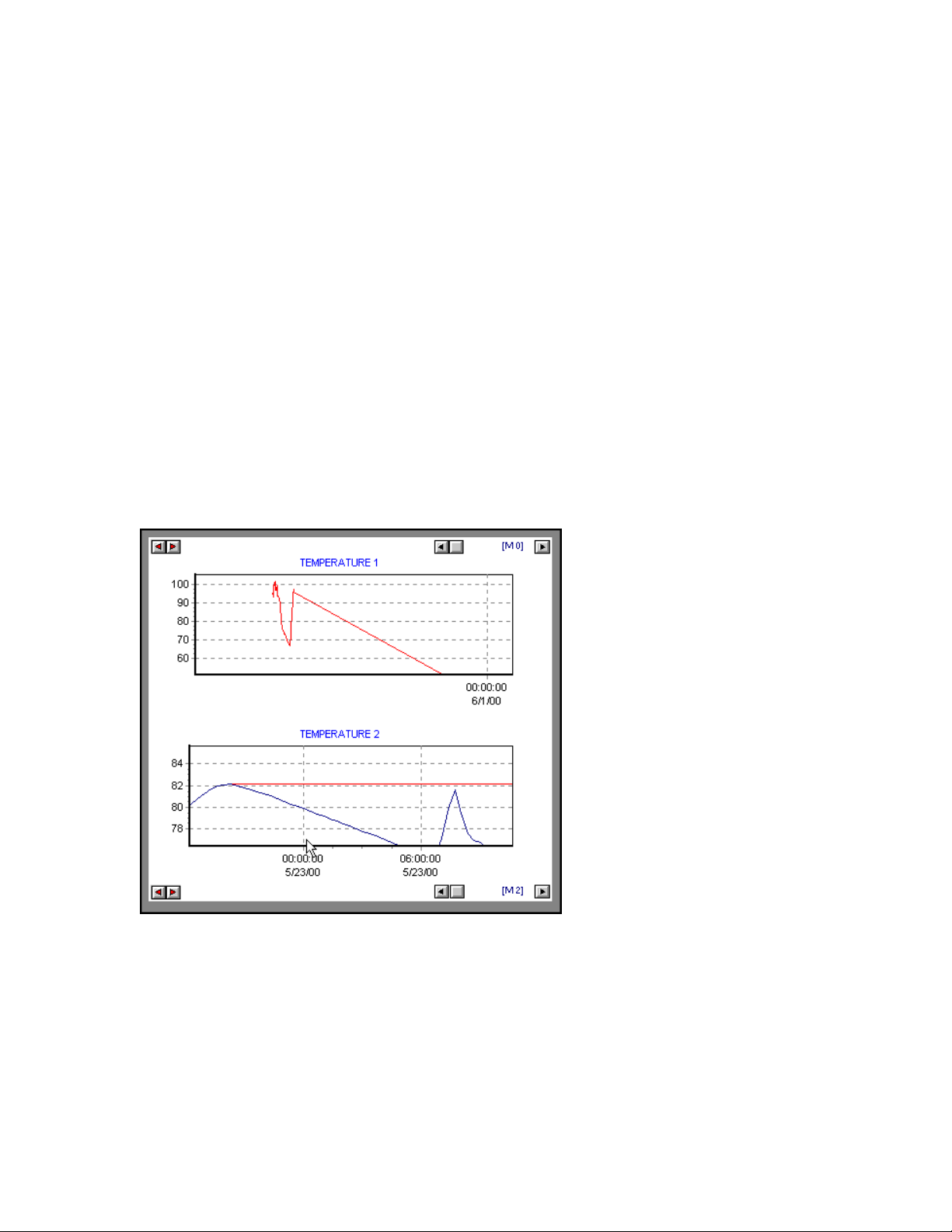
WMS-16STR Windows Graphical Page 89
Software Display Reference
The backup command is found by selecting the File | Project menu item. Enter a new project
name and then click the Backup Project button. Your current project will be saved to the new
backup folder.
The Backup command backs up the form files, the alarm setup files, the password files, data files
and the initialization files for your new directory.
Note: Back up your data files by using windows explorer to copy these files to a new directory.
These files may become very large, and may need to be removed to make room for new data
files.
TRENDS
Real Time Trends
Changer Buttons on left
Scroller on right (A 0 shows the
trend to be in automatic mode
Real time trends, right click the trend to set properties.
Right click the scrollbar to toggle between automatic scaling and manual scaling.
Click the changer button to change bottom scale time.
The real time trend has many of the same features at the Button Chart. Only this trend is showing
the trend data all the time.
Right Clicking
Right click on the trend and on the scrollbar. Properties are toggled on and off and can be set by
right clicking.
M-3834-0602 WMS-16STR WINDOWS GRAPHICAL SOFTWARE MANUAL.doc Page 89 of
89
Page 90

WMS-16STR Windows Graphical Page 90
Software Display Reference
Right Click On The Scrollbar
If you right click on the scrollbar, the trend changes from automatic datetime scaling to manual
datetime scaling. Manual date time scaling allows you to stretch the data and to view only a
portion of the data. Automatic datetime axis shows all the data in the trend.
DateTime Changer
The datetime changer is a dual button that allows you to go short the datetime span or to lengthen
the datetime span. There are 21 settings you can expand to (from 1 second to 1 year). Each
click on the date time changer changes the trend to the manual mode. A hint shows up when the
mouse is over the datetime changer that shows its current setting.
Right Click On Trend
Right click on the trend to present the property forms for the trends. These properties are the
same for the button chart. Goto Button Charts to see all the property options
Trend Properties
M-3834-0602 WMS-16STR WINDOWS GRAPHICAL SOFTWARE MANUAL.doc Page 90 of
90
Page 91
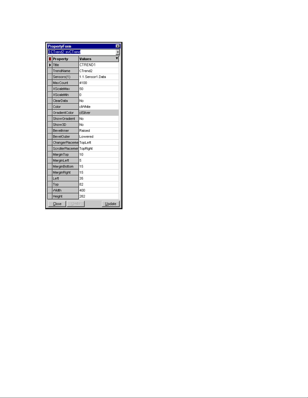
WMS-16STR Windows Graphical Page 91
Software Display Reference
No special properties are used in the trends
M-3834-0602 WMS-16STR WINDOWS GRAPHICAL SOFTWARE MANUAL.doc Page 91 of
91
 Loading...