

Page 1

TABLE OF CONTENTS
In Chapter 1
Contents
Features at a Glance
Chapter 1 Introduction
General Information
Features and Configurations
WB-FLASH12 operator’s Manual
iv
1 – 1
1 – 4
FLPC E01/P01 06/95
i
Page 2

WB-FLASH12 OPERATOR’S MANUAL
In Chapter 2
Table of Contents
ii
Contents
Chapter 2 Installing the WB-FLASH12
Overview
Verifying WB-FLASH12 Switch Settings
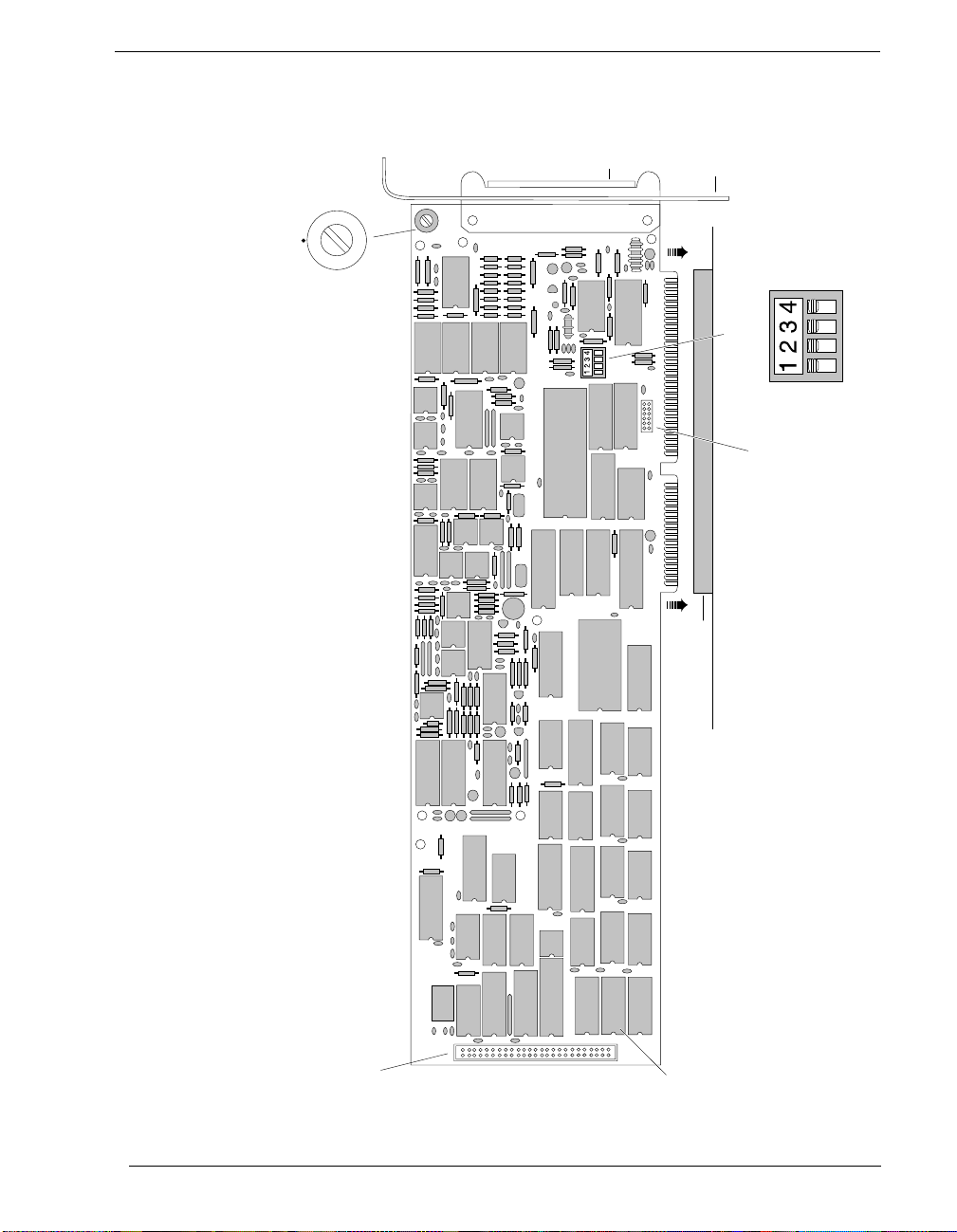
Illustration of the WB-FLASH12 Board
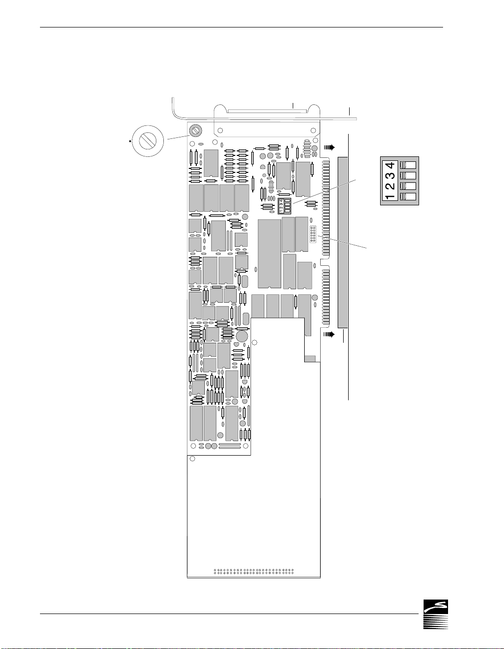
Illustration of the WB-FLASH12 Board with Daughterboard
Physical Board Installation
Setting the Board Number Switch
Setting the Base Address
Single-Ended vs. Differential Inputs
2 – 1
2 – 2
2 – 3
2 – 4
2 – 5
2 – 7
2 – 9
2 – 11
Page 3

TABLE OF CONTENTS
In Chapter 3
Contents
Chapter 3 Technical Notes
Overview
Pin Assignments for WB-FLASH12
Block Diagram of WB-FLASH12
Block Diagram of WB-FLASH12 Daughterboard
Triggering
Using EDITCAL
Changing Hardware Interrupts
Troubleshooting: Installation
Troubleshooting: Operation
Specifications of the WB-FLASH12
WB-FLASH12 operator’s Manual
3 – 1
3 – 2
3 – 3
3 – 4
3 – 5
3 – 8
3 – 10
3 – 11
3 – 12
3 – 15
iii
Page 4

WB-FLASH12 OPERATOR’S MANUAL
Features at a Glance
Highlights of the WB-FLASH12 Models
Maximum Speed
Model 1:
Model 2:
1MHz, Single Channel
1MHz, Multi-Channel
1MHz, Single Channel
400kHz, Multi-Channel
Maximum Resolution
Model 1:
Model 2:
14 Bits (.006%)
14 Bits (.006%)
Analog Input Gain Ranges
Model 1:
15 selectable Ranges
Model 2:
1 Fixed Range
All Models of the WB-FLASH12 Feature
16 Single-Ended or 8 Differential Analog Input
channels · 8 Digital I/O lines, user configurable · Input
protection to 30 Volts, operating · On-board pacer
clock · Wide acceptance of sensor devices · Pre- and
Post-Triggering · On-board counter/timer · Optional
daughterboard, featuring two analog outputs and additional
memory · Factory guaranteed accuracy for two years from
date of purchase
Front Matter
iv
Page 5

INTRODUCTION
General Information
Chapter 1: Introduction to the
WB-FLASH12
Thank you for selecting the WB-FLASH12 for your project!
Our primary objective is to provide you with data acquisition systems that
are easy to install, operate, and maintain. W e also strive to furnish the performance you need at the lowest overall cost. The benefits for you are increased
productivity, data you can count on, and, of course, meeting your budget.
We manufacture the WB-FLASH12 as an enhancement board that readily
mounts in an ISA expansion slot in an IBM PC, or -compatible, computer.
This product’s high speed, extensive timing features, and its guaranteed long
term stability make it ideal for speed-critical applications in both the laboratory and harsh industrial environments.
Using the WB-FLASH12 board together with our graphical interface application software (such as WorkBench PC™ for Windows or DOS, or QuickLog™ PC), you can easily and very quickly implement a broad spectrum of
research and commercial tasks, in a wide variety of settings. You can, for example,
· Display and log data
· Measure temperature, pressure, flow
· Perform scale, offset, or complex calculations
· Monitor and control processes
· Set alarm limits
· Control devices at preset levels
· Control devices from digital input
· Gather data unattended
You can use the system interactively, operating controls or modifying your
setup while the system is running.
to disk for later analysis,
and most other analog inputs
from sensors and instruments,
on a measurement,
,
on any input,
(fans, pumps, heaters, etc.),
(e. g., from switches or TTL
signals), and
.
WB-FLASH12 Operator’s Manual
1 – 1
Page 6

WB-FLASH12 OPERATOR’S MANUAL
DEVELOPMENT
EXPANDABILITY
RANGES/
DATA
HALF-FLASH
General Information
People who decide, on the other hand, to write their own software
SYSTEM
(rather than using an off-the-shelf application) can employ the
Analog Connection Development System™ hardware driver to
address all features of the WB-FLASH12 board from within a pr ogram they design and code for their specific purpose.
A WB-FLASH12 product has eight differential (or 16 single-ended) analog input channels; and you can add one board at a time to
your computer, for as many as 15 boar ds with a total of 120 analog
input channels (240 single-ended) and 120 digital input/output
lines!
(Note that the installation is limited to five boards when using our
DOS software.)
The 15 input ranges of the WB-FLASH12 Model 1 span from 50
UNITS OF MEASURE
milliV olts thr ough 10 V olts, capable of accepting data fr om almost
any sensor. Its high conversion rate also makes the WB-FLASH12
ideal for high speed measurement in the plant or laboratory.
The WB-FLASH12 together with our software – such as WorkBench PC for Windows or DOS and QuickLog PC – make it easy
to specify engineering units (degrees, V olts, milliAmperes, etc.) for
measurements, as well as which ranges to use.
PRESENTATION
CONVERTER
Chapter 1 Introduction
1 – 2
(You can measure temperature, for example, by selecting from
among 11 different thermocouple types. With our application
software, the process simply consists of selecting the type of sensing device from a menu – the driver automatically handles cold
junction compensation and linearization.)
The combination of our hardware and application software
(WorkBench PC for Windows or DOS or QuickLog PC) enables
both the display of data on the screen, and the logging of data to
disk for later analysis.
The system is capable of showing data on the monitor in a variety
of formats, including graphical meters. Charts can indicate trends
for comparison of actual measurements on several channels, or for
setting data points or alarms.
Your WB-FLASH12 incorporates our unique “Half Flash” converter, greatly improving the board’s speed.
In analog to digital conversion, the highest speed designs use
what is called a “flash” converter. Flash converters are unique in
that they use comparators – one for each bit – to detect whether
an analog input signal is higher or lower than a particular reference point. The output of all comparators is encoded by digital
logic to then yield the digital output. Because the conversion
Page 7

INTRODUCTION
General Information
takes only as long as it takes for the comparators to detect the
input level, conversion rates of greater than 50 nanoseconds are
easily achieved.
Despite their speed, flash converters are rarely used in data acquisition products. Because there are as many comparators as there
are bits (an 8-bit converter has 28 = 256 comparators!), they are
quite expensive to produce.
For the WB-FLASH12 boards, we developed a unique “half flash”
converter which overcomes the expense and complexity of a full
flash converter. With the half flash converter, the A/D conversion
takes place in two steps: 1) a rough approximation of the digital
code is generated, and 2) the approximation is adjusted to the
correct value.
While this two step process is slower than the flash converter, it
will still yield conversion rates of up to 1µs, or 1MHz. Because of
this unique process, the WB-FLASH12 is one of the fastest data
acquisition boards in the industry!
WB-FLASH12 Operator’s Manual
1 – 3
Page 8

WB-FLASH12 OPERATOR’S MANUAL
ANALOG
RESOLUTION
DATA ACQUISITION
RANGES
SENSORS
ACCURACY
INPUT
PROTECTION
ANALOG OUTPUT
DIGITAL I/O
COUNTER/TIMER
OPTIONAL
Features and Configurations
Features and Configurations
The WB-FLASH12 line consists of two models: the WB-FLASH12
Model 1 and the WB-FLASH12 Model 2. The boards possess these
features:
Both models of the WB-FLASH12 can be set for either eight differ -
INPUT CHANNELS
SELECTIONS
ential or 16 single-ended analog inputs.
The resolution of your WB-FLASH12 is selectable in software,
ranging from12 through 14 bits.
The maximum single-channel acquisition rate for both models of
the WB-FLASH12 is 1MHz. For the Model 1, the maximum mul-
SPEED
tichannel rate is 1MHz, while the Model 2 can sample multiple
channels at up to 400kHz.
The WB-FLASH12 Model 1 features 15 voltage ranges, from
±15mV up to ±10V, all selectable individually for each analog input
channel.
The WB-FLASH12 Model 2 has a fixed gain range of ±5V.
CHANNELS
DAUGHTERBOARD
Chapter 1 Introduction
1 – 4
Each WB-FLASH12 provides accurate cold junction compensation and linearization for thermocouple devices when used with
appropriate terminal panels.
We guarantee the factory calibration of the WB-FLASH12s for a
period of two years from the date of purchase. (If it is ever necessary, the user can recalibrate the board with precision through the
use of software utilities we provide with every product.)
Built-in circuitry assures protection of analog input channels for
±30 Volts operating, or ±20 Volts non-operating.
The optional daughterboard for the WB-FLASH12 includes two
analog output channels, each with five software selectable gain
ranges.
All WB-FLASH12s feature 8 digital input/output channels that
the user can configure individually to be input or output.
Every WB-FLASH12 board includes a counter/timer for precise
timing (for counting pulses or other events) which you can use as
a pulse output.
An optional daughterboard (DB03-M) is available for the
WB-FLASH12 that will increase its memory from 64k samples to
1M samples; it also includes two analog outputs. In addition, the
DB03-M features an analog output buffer.
Page 9

TERMINAL
PANELS
FOR MORE
WB-FLASH12 SYS
INFORMATION
TEM
REQUIREMENTS
INTRODUCTION
Features and Configurations
Other available accessories for the WB-FLASH12 include your
choice of screw fastener terminal panels for connecting sensors.
They include general purpose and thermocouple terminal panels,
most of which accept digital opto-isolators.
For more information about the capabilities of your
WB-FLASH12, please see “Product Specifications” in Chapter 3.
For instructions on controlling the board with our interface software (such as WorkBench PC for Windows or DOS or QuickLog
PC), refer to the appropriate software manual.
To learn more about data acquisition and process control in general, and how to use our products together to accomplish everyday tasks, consult our
Applications
manual.
And, last but not least, if you’re creating your own program to
address the WB-FLASH12 for a custom purpose, please see the
Analog Connection Development System Manual.
Before installing the WB-FLASH12, make sure the computer sys-
-
tem fulfills these minimum requirements:
Hardware –
· IBM PC XT, AT, (or higher), or -compatible
640k system RAM and full-size ISA slot,
· Floppy disk drive
Software Environment –
· DOS 3.0
(or higher, depending on the application software),
· Application software
and a hard drive.
(WorkBench PC for Windows or DOS,
QuickLog PC, the Analog Connection Development System, or other compatible proprietary software; please see
your software manual for directions for using it with the
hardware).
, with at least
WB-FLASH12 Operator’s Manual
1 – 5
Page 10

WB-FLASH12 OPERATOR’S MANUAL
Chapter 1 Introduction
1 – 6
Page 11

INSTALLATION
Chapter 2: Installing the WB-FLASH12
Getting your WB-FLASH12 data acquisition and process control board up
and running is a straightforward process; you only need to
Overview
· Verify the board’s switch settings
system addressing of OMEGA products (see page 2 – 2),
· Physically insert the board
(page 2 – 5; and illustration on 2 – 3),
· Connect a terminal panel to the board
and for digital outputs from the WB-FLASH12; see page 2 – 5),
and
· Load and start up the software
As the scope of this manual focuses on the WB-FLASH12 board, this chapter discusses board’s switch settings, and the physical insertion of the board.
Please see your terminal panel manual for full instructions regarding its
attachment to the WB-FLASH12, as well as for how to connect sensors to
the panel.
Guidelines for loading the software, and for starting up, depend on the
application program you are going to use (such as our WorkBench PC for
Windows or DOS, or QuickLog PC, or a package by a third party developer
who has our authorization).
The program you are going to use with the WB-FLASH12 might even be
unique and proprietary, a product of your organization. (The Analog Connection Development System is a powerful set of utilities making it possible
for software engineers to design and develop their own programs to exploit
the WB-FLASH12’s many features.)
that control board identity and
into a slot of the personal computer
(to attach sensing devices
to be used for the project.
In any event, please refer to the software provider’s installation manual, or
user guide, for specific information on how to load and run the particular
program.
Troubleshooting –
to the “Troubleshooting” section in Chapter 3.
Strawberry Tree
If you have any difficulty getting your board to work, refer
WB-FLASH12 Operator’s Manual
2 – 1
Page 12

WB-FLASH12 OPERATOR’S MANUAL
SINGLE BOARD
MULTIPLE
PREVIOUSLY
Verifying Switch Settings
Verifying WB-FLASH12 Switch Settings
When you purchase a data acquisition board new from our company, the product’s switch settings already are correct to operate a
single
board with our software (WorkBench PC for Windows or
DOS, QuickLog PC, the Analog Connection Development System, and all others).
This means the factory switch settings are right for the purpose of
using only one board, and you can skip the task of confirming
them. You can go directly to the “Physical Board Installation” section on page 2 – 5 in this chapter, and begin to follow the steps
there.
If you are using more than one board at a time, set the individual
BOARDS
boards’ Board Number Switch first (refer to “Setting the Board
Number Switch” on page 2 – 9), then go on to perform the physical installation.
Otherwise, there’s no reason to be concerned about the board’s
switch settings, except in the unlikely event you encounter a
problem in getting your product to operate. (If you experience a
problem, refer to “Troubleshooting” in Chapter 3).
Chapter 2 Installation
2 – 2
IN USE
If, on the other hand, your board has been in use previously in
another computer, or if your company uses its own proprietary
software, the present switch positions might differ from the factory settings.
If your company uses such a program, making changes to factory
switch settings might be necessary to accommodate it. Please
consult the administrator of your internal system, or the provider
of third party software, to determine their recommendations for
any unusual switch setting.
To check and restore the factory values, please read “Board Number Switch Settings” on 2 – 8 in this chapter.
Page 13
D
E
F
0
1
2
3
4
5
Board Number
switch (detail:)
–
INSTALLATION
WB-FLASH12 Board
Attach
cable
connector
from
terminal
panel
here
Back
panel
mounting
bracket
C
B
A
9
8
7
6
SW1
Base Address
SW2
insert; seat firmly
switches (detail:)
Interrupt Jumpers
Strawberry Tree
PC ISA expansion slot
U5
U7
U6
Figure1. Illustration of FLASH-12 Data Acquisition Board, Showing Physical Installation
Daughterboard Connector
(50 pins)
DRAM chips
(U5, U6, U7)
WB-FLASH12 Operator’s Manual
2 – 3
Page 14
WB-FLASH12 OPERATOR’S MANUAL
WB-FLASH12 with Daughterboard
D
C
E
B
F
A
0
9
1
8
2
7
3
6
4
5
Board Number
switch (detail:)
–
Attach
cable
connector
from
terminal
panel
here
Back
panel
mounting
bracket
SW1
Base Address
switches (detail:)
SW2
Interrupt Jumpers
insert; seat firmly
Figure 2. Illustration of FLASH-12 Data Acquisition Board, with Optional Daughterboard Installed
Chapter 2 Installation
2 – 4
PC ISA expansion slot
Page 15

TERMINAL PANEL
PHYSICAL
CONNECTIONS
INSTALLATION
Physical Installation
Physical Board Installation
Installation very simply consists of inserting the board into an
open ISA AT (long) peripheral (expansion) slot inside your computer.
(There are, for example, five available slots in the IBM PC, and
eight in the IBM XT or AT. IBM and other companies sell expansion chassis that can accept even more analog cards. Our Windows software supports as many as 15 WB-FLASH12 boards at
one time; up to five can be installed for use with our DOS software.)
When using a terminal panel with the WB-FLASH12 (to connect
external devices: sensors and digital input/output) you are going
to be using a single ribbon cable from the terminal panel. This
cable plugs into a 50 pin connector at the back panel of the WBFLASH12 and, at its far end, plugs into a 50 pin connector at the
terminal panel. Each 50 pin cable connector has a key on one
side that mates with a socket on the device; be sure to observe
polarity when attaching.
Strawberry Tree
INSTALLATION
(Refer to the illustration on page 2 – 3. Also see “Pinouts,” on
page 3 – 2 of this manual, for a description of the signals.)
To Install the WB-FLASH12 Board –
1.
TURN THE COMPUTER OFF!
puter without first turning its power switch to the “off” position.
2.
Open the Computer.
appropriate, refer to your computer’s owner’s manual for
more information about removing the cover and installing
enhancement boards.)
3.
Ground Yourself.
touch the metal chassis of the computer to discharge any
static electricity that might be on the surface of your body.
This is important, as static electricity can damage electronic
parts. (Likewise, if you ever remove the board from the computer, always store it in its protective shipping bag.)
4.
Remove
unscrew and remove the narrow dust cover plate that is
directly behind the expansion slot you want to use. (Keep this
screw handy.)
the Dust Cover.
While holding the board, before installing it,
Never remove the cover of the com-
Remove the cover of the computer. (If
At the back panel of the computer,
WB-FLASH12 Operator’s Manual
2 – 5
Page 16
WB-FLASH12 OPERATOR’S MANUAL
CAUTION
NEXT STEPS
Physical Installation
5.
Insert the Board.
having “gold fingers” down and into a twin connector expansion slot (socket) on the chassis so that the contacts align
with the socket, then plug it in by pushing the board straight
down.
6.
Fasten the Board to the Chassis.
from step 4. Place it in the original hole, through the WBFLASH12 board’s bracket, so that it fastens the top of the
bracket to the computer’s back panel.
7.
Connect the Cable to Board and T erminal
the data acquisition board, and the connector on its far end
into the socket on the terminal panel (please refer to your terminal panel’s manual, if you are unsure about the correct
position).
Incorrect installation of these cables can damage the data
acquisition board or the terminal panel. (If you are uncertain
about proper placement, please see “Terminal Panel Connections” at the beginning of this discussion, and inspect the diagram on page 2 – 3.)
Single Board Usage –
sition board in your system, you are now ready to install your application software and to connect sensors to your terminal panel.
Push the edge of the WB-FLASH12 board
Install the “left over” screw
Panel.
Plug the cable into
If you intend to run with a single data acqui-
Chapter 2 Installation
2 – 6
Multiple Board Usage –
If you are going to use more than one data
acquisition board, now it’s time to set each Board Number Switch
to an unique number. Follow the steps in the “Setting the Board
Number Switch” section in this chapter on page 2 – 9.
Installing the Software –
For information on loading and configuring our WorkBench PC for Windows or DOS or QuickLog PC
please refer to the user guide for that application package.
IMPORTANT! Setting the Analog Input Mode –
You must set the Analog Input mode in the software before using the WB-FLASH12.
See “Single-Ended vs. Differential Inputs” on page 2 – 13.
Installing the T erminal Panels –
T o learn how to connect experiments
to the terminal panel see your terminal panel owner’s manual, or
our Applications manual (which discusses data acquisition and
control in general and provides examples of uses for the pr oducts).
Page 17

INSTALLATION
MULTIPLE BOARDS
SINGLE BOARD
DISABLING BOARDS
SETTING
Setting the Board Number Switch
Setting Board Number Switch
When you are using multiple boards in your installation, each
board needs to have an identity for the software to recognize it as
an “individual.”
The Board Number switch on a board accomplishes this, as it
enables you to set an identifying number for the board (see the
illustration on page 2 – 3).
This number determines, among other things, the sequence in
which the software reads multiple boards. OMEGA programs can
address as many as 15 boards total (but if you are working in
DOS, no more than 5 of these boards can be from the high speed
family, i.e. WB-FLASH12 or WB-WORKMATE boards).
When using more than one OMEGA product in your installation,
every board’s Board Number switch needs to have a different
number setting, and all switches are to be in number sequence
(1, 2, 3, for example, if you are using three boards).
THE SWITCH
(If you are working in DOS and there are also WB-AAI/F AI family
boards in your installation, then their Board Numbers need to be
at the low end of the number sequence.)
If your system includes just a single data acquisition board, then
you don’t need to have much concern about the Board Number
switch.
When your WB-FLASH12 leaves our manufacturing facility, we
set the Board Number switch to 1, and this is the setting we recommend for most purposes when you are using only one board
in your installation.
If you want to disable the board, for any reason, set its Board
Number switch to 0. (This is handy if you want to use fewer
boards for a while: that way you don’t have to r emove them from
the computer.)
To Set the Board Number Switch –
1.
Locate
the Switch.
examine the illustration on page 2 – 3 in this chapter and find
the “Board Number Switch” on the WB-FLASH12.
On the printed circuit board, this is a rotary switch with the
label “SW1.”
With the cover of your computer removed,
Strawberry Tree
WB-FLASH12 Operator’s Manual
2 – 7
Page 18

WB-FLASH12 OPERATOR’S MANUAL
Setting the Board Number Switch
2.
Make
the Setting.
numbers on the detents are 0 through 9 and A through F.
Determine which is to be the First Board. (This is easy, if it is
the sole board.) Then turn its dial to 1. Determine which is to
be the Second Board, then set its switch to 2. Continue this
process until all of the boards have been assignedand set to a
unique number.
Note that the switch has 16 possible positions:
If you are working in DOS –
to use system installation digital I/O channels 1-8 and analog
The software interprets First Board
input channels 1 through 8 (or channels 1 through 16 for
single-ended inputs). The program then recognizes the Second Board to use system installation digital I/O channels 9-16
and analog input channels 9 through 16 (for differential
inputs), or system installation analog input channels 17
through 32 (if the inputs are single-ended).
3.
Set
All Switches.
Continue to set the switches for all boards in
your installation to unique numerical values in an unbroken
sequence.
(As various models of our boards use different kinds of
switches, please see their operator’s manuals for an explanation of how to set switches.)
Chapter 2 Installation
2 – 8
Page 19

INSTALLATION
SETTING WB
Setting the Base Address
Setting the Base Address
The Base Address determines the logical system address where
the personal computer expects to find all data acquisition boards.
Base Addresses must be the same
The factory setting for all of our data acquisition products is
300H (in hexadecimal format).
on all boards.
FLASH12
It is rarely necessary, but if you have difficulty getting the board to
work you can change these switches to values different from the
factory settings. (Another device in your PC, for example, might
be trying to use the same Base Address.)
Indications of this are: if the program reports it cannot find your
board, or if it reports fewer boards than you really have, or if
another board starts to work improperly after you install the WBFLASH12.
These problems indicate interference with another board using
the same base address as the WB-FLASH12 product.
Remedy the problem by changing the switches of all WBFLASH12 boards to an address that has no conflict. (If you have
boards other than WB-FLASH12s in your system, please refer to
their operator’s manuals for instructions.)
To Set the Base Address –
-
1.
Locate
the Address Switches.
puter over the data acquisition board, and find the location of
the Base Address switches. Refer to the board illustration on
page 2 – 3 in this chapter and find “Base Address Switches”
on the WB-FLASH12 diagram.
On the printed circuit board itself, this is a block of four DIP
switches labeled “SW2.”
Remove the cover of your com-
Strawberry Tree
(NOTE: Depending the space available in your installation, it
might be necessary to remove the board to reach the Base
Address Switches. If so, please follow the same precautions as
in “Physical Installation” on page 2 – 5 in this chapter.)
2.
Change
the Setting.
sists of all four DIP switches’ being in the “up” position (when
the board is sitting in the computer’s expansion slot).
The DIP switches have the labels “1” through “4.” Sliding a
switch to the “down” position adds a value to 300H:
300H is the normal base address. It con-
WB-FLASH12 Operator’s Manual
2 – 9
Page 20
WB-FLASH12 OPERATOR’S MANUAL
CAUTION
Setting the Base Address
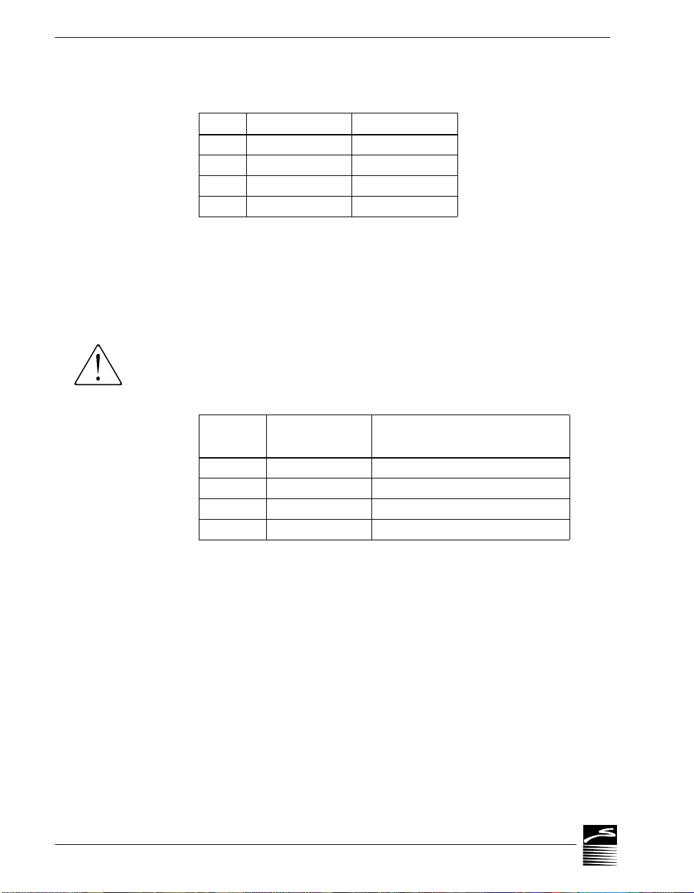
WB-FLASH12 Base Address Switch Additive* Values –
Switch Position To 300H Add
1 Down 10H
2 Down 20H
3 Down 40H
4 Down 80H
* As the switches are additive, your sliding
Switches 1 and 4 down, for example, is going to
add 10H and 80H to the 300H, equalling 390H.
If you are having a problem with Base Address, we recom-
mend first trying 340H as an alternative to the factory setting
of 300H.
Values to Avoid –
There are several Base Address values you
need to avoid, that we know can cause interference with
other devices in some PC installations:
WB-FLASH12 Base Addresses to Avoid –
Value
320H – U U D
370H – U D D
3C0H – D D U
3F0H – D D D
* U = Up D = Down – = any position
Switch Positions*
1 2 3 4
Can Interfere With
Hard disk drive
Parallel printer
Color Monitor
Floppy disk drive
Chapter 2 Installation
2 – 10
Page 21

INSTALLATION
MULTIPLE BOARDS
S
Single-Ended vs. Differential Inputs
Single-Ended vs. Differential Inputs
In the Single-Ended mode, the WB-FLASH12 has 16 analog
input channels, each of which can measure a different voltage relative to ground.There are eight analog input channels available in
Differential mode; each channel can measure the difference voltage between the positive and negative inputs.
The WB-FLASH12 is shipped from the factory in Differential
Mode. Follow the instructions below if you wish to change this.
SETTING THE
ANALOG INPUT
MODE IN DOS
IN DO
To Set the Analog Input Mode (if you are using DOS) –
1. Install the Driver Software.
both driver and application software (QuickLog PC or WorkBench PC for Windows or DOS). The driver software resides
on both the QuickLog and the WorkBench disk, and will be
automatically installed when you run either installation program. (Please consult the appropriate software manual for
further information on installation.)
2. Run the GFIND Program.
S.” This will tell the GFIND program to show you the current
configuration of all cards in your computer.
3. Type the Board Number.
FLASH12 in your installation must be set individually.
4. Select the Analog Input Mode.
for Differential mode. To write the changes to the boards’
EEPROMs, you must type “W” after making your selection.
5. Quit the Program.
“Q” at the prompt.
The new settings will be remembered by each board until it is
reprogrammed.
When you are using multiple boards in your installation, the software automatically numbers the analog and digital input and output channels in a sequential order, beginning with the channels
on Board Number 1.
You may now exit the program by typing
All WB-FLASH12 boards ship with
At the DOS prompt, type “GFIND –
The Analog Input Mode for each WB-
Type “S” for Single-Ended or “D”
Strawberry Tree
For example, if you have installed two WB-FLASH12 boards,
both set in Differential mode, the software will assign Board 1
analog input channels 1 through 8 and digital I/O channels 1
through 8. Board 2 will be assigned analog input channels 9 to 16
and digital input channels 9 to 16. Because both boards are set in
Differential mode, the channel assignment is fairly straight-
WB-FLASH12 Operator’s Manual
2 – 11
Page 22

WB-FLASH12 OPERATOR’S MANUAL
Single-Ended vs. Differential Inputs
foward.
If your installation includes boards that are set in different modes,
however, the channel numbering can be a bit more complicated.
The following Channel Locator Chart defines possible analog
input channel assignments in multiple (up to 3) board setups:
Channel Locator Chart –
Total # Board 1 Board 2 Board 3
Boards Diff. Single Diff. Single Diff. Single
11 to 8–––––
1–1 to 16––––
2 1 to 8 – 9 to 16 – – –
2 1 to 8 – – 9 to 24 – –
2 – 1 to 16 17 to 24 – – –
2 – 1 to 16 – 17 to 32 – –
3 1 to 8 – 9 to 16 – 17 to 24 –
3 1 to 8 – – 9 to 24 25 to 32 –
3 1 to 8 – 9 to 16 – – 17 to 32
3 1 to 8 – – 9 to 24 – 25 to 40
3 – 1 to 16 17 to 24 – 25 to 32 –
3 – 1 to 16 – 17 to 32 33 to 40 –
3 – 1 to 16 17 to 24 – – 25 to 40
3 – 1 to 16 – 17 to 32 – 33 to 48
Analog Input Channel Assignments
Chapter 2 Installation
2 – 12
Page 23

TECHNICAL NOTES
General Information
Chapter 3: Technical Notes
Although operations in this chapter are seldom necessary during everyday
data acquisition, you might want to refer to them at certain times during
operation of the WB-FLASH12. They are
· Pinouts (at the board’s connectors, in the event you want to connect analog or digital signals directly, without using a terminal
panel; please refer to page 3–2);
· Block diagram of the WB-FLASH12 and daughterboard showing onboard processing (please see page 3–3 and 3–4);
· Triggering the WB-FLASH12 to synchronize the data acquisition activity
to some external or internal (see page 3–5 to 3–7);
· Using EDITCAL to accommodate changes to your installation, (on pages
3–8 to 3–9);
· Changing har dwar e interrupts in or der to avoid conflicts with other
· Troubleshooting: some possible problems and solutions after install-
· Specifications: complete specifications of both WB-FLASH12 models
Strawberry Tree
hardware (please see page 3–10);
ing, and during operation of the WB-FLASH12
(beginning at page 3–11);
and the optional DB03-M daughterboard (beginning
at page 3–14).
WB-FLASH12 Operator’s Manual
3 – 1
Page 24
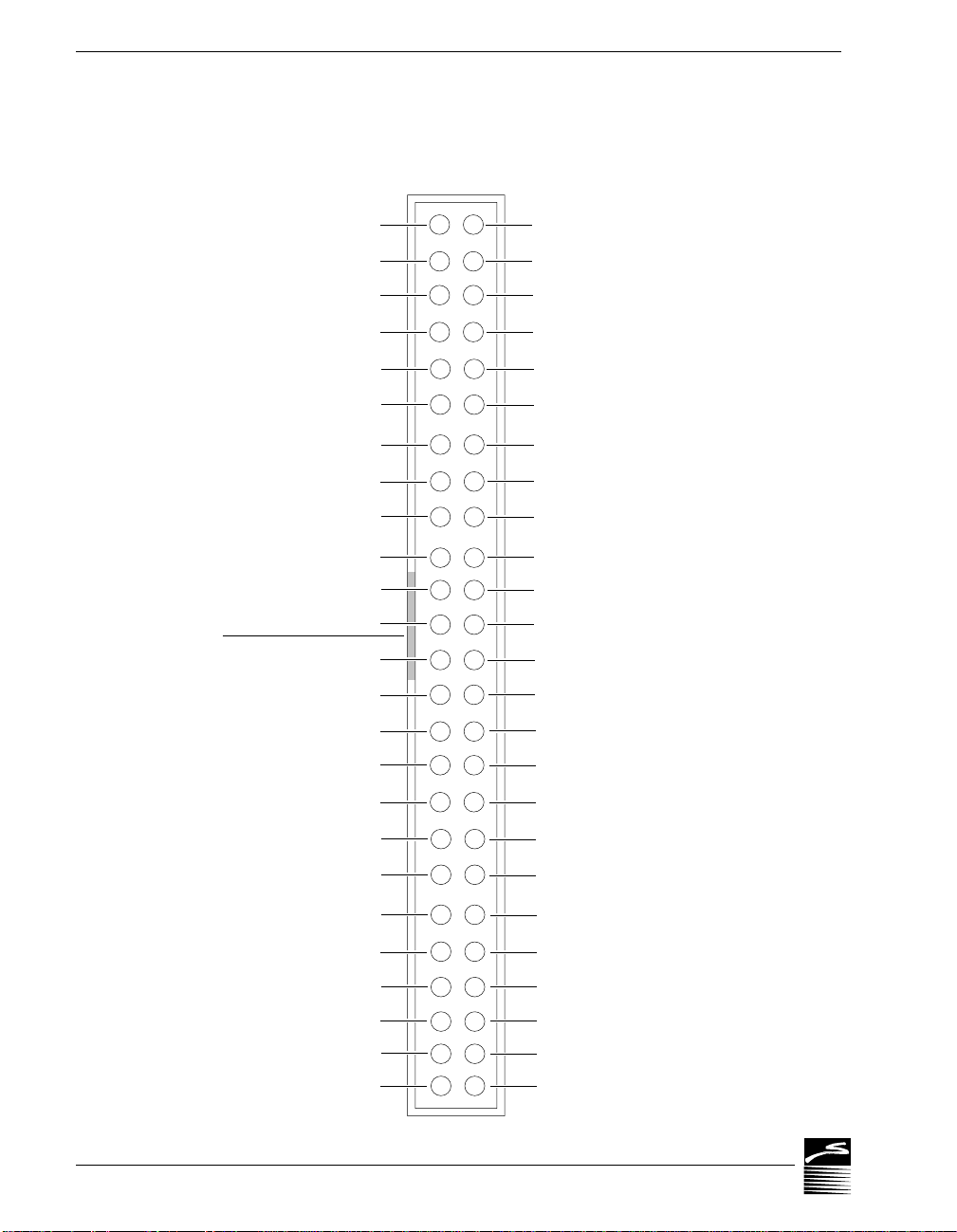
WB-FLASH12 OPERATOR’S MANUAL
Pin Assignments
Figure 3. Pinouts of the WB-FLASH-12 at Back Panel Connector –
Single-Ended / Differential Differential / Single-Ended
channel 9 / channel 1 –
channel 10 / channel 2 –
channel 11 / channel 3 –
channel 12 / channel 4 –
channel 13 / channel 5 –
channel 14 / channel 6 –
channel 15 / channel 7 –
channel 16 / channel 8 –
Analog ground
Cold junction sensor (+)
Analog Ground
Connector
Analog Ground
key notch
N/C (do not connect)
Conversion gate
Analog Output 1
– 12 Volts
2
1
4
3
6
5
8
7
10
9
12
11
14
13
16
15
18
17
20
19
22
21
24
23
26
25
27
28
29
30
31
32
channel 1 + / channel 1
channel 2 + / channel 2
channel 3 + / channel 3
channel 4 + / channel 4
channel 5 + / channel 5
channel 6 + / channel 6
channel 7 + / channel 7
channel 8 + / channel 8
Analog ground
+6.666 Volt Ultra-Stable Reference
+ 5 Volts
Analog ground
+ 12 Volts
N/C (do not connect)
Analog trigger input
Analog Output 2
(CT Gate) digital I/O 8
(CT Trig) digital I/O 7
(CT In) digital I/O 6
(CT Out) digital I/O 5
Chapter 3 Technical Notes
3 – 2
digital I/O 4
digital I/O 3
digital I/O 2
digital I/O 1
+ 5 Volts
34
33
36
35
38
37
40
39
42
41
44
43
46
45
48
47
50
49
digital ground
digital ground
digital ground
digital ground
digital ground
digital ground
digital ground
digital ground
Digital trigger input
Page 25
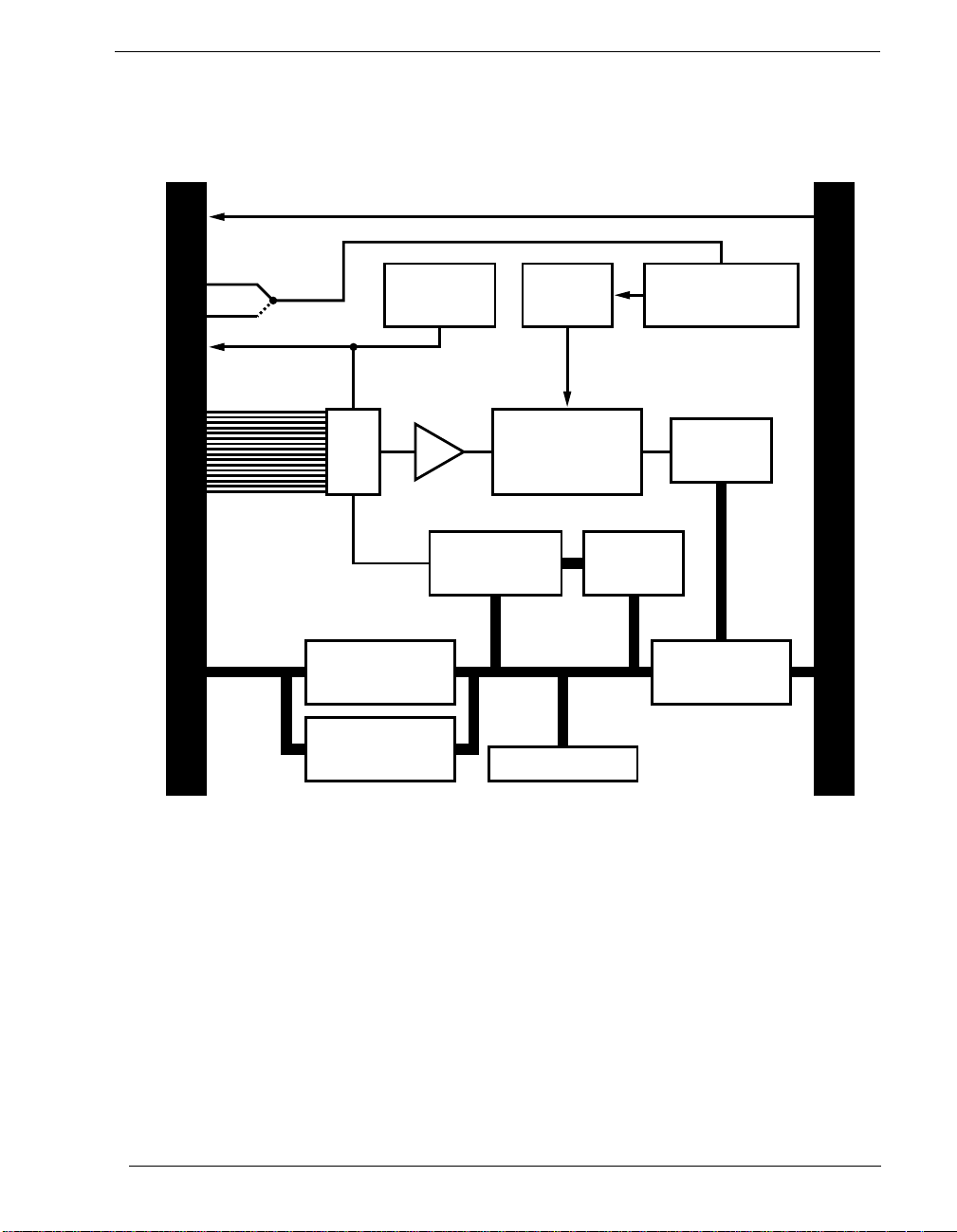
Figure 4. Block Diagram of WB-FLASH-12 (Both Models) –
+5V, ±12V
Analog or
Digital Trigger
Reference
Voltage
Pacer
Clock
16 se or 8 diff
Analog Inputs
Amplifier
TECHNICAL NOTES
Block Diagram of WB-FLASH12
Trigger &
Trigger Counters
Real World
8 Digital
I/O Lines
MUX
I/O
Latches
Counter/
Timer
Re-Circulating
Flash Converter
Gain & Channel
Control
To Daughterboard
Memory
Buffer
Computer Bus
Sequence
RAM
Computer Bus
Interface
Strawberry Tree
WB-FLASH12 Operator’s Manual
3 – 3
Page 26
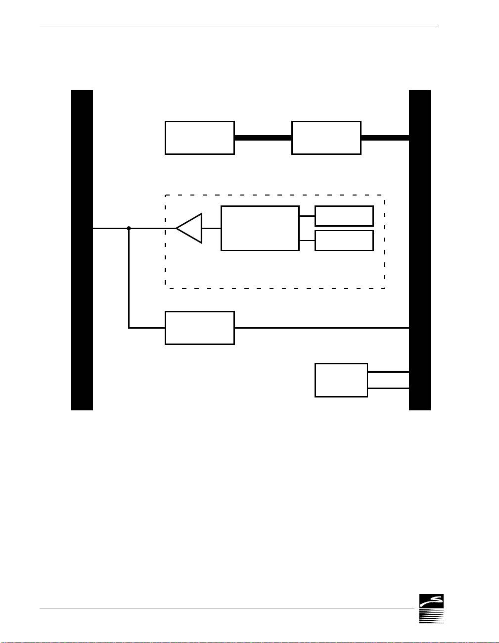
WB-FLASH12 OPERATOR’S MANUAL
Block Diagram of Daughterboard
Figure 5. Block Diagram of WB-FLASH-12 Daughterboard –
RAM Bank
1024kWords
2 Analog
Outputs
12-Bit D/A
Converter
Amplifier
Real World
1 converter, amplifier, latch, and buffer (opt.) per channel
RAM Buffering
& Logic
RAM Buffering
& Logic
256k Buffer
Latch
FLASH-12 Board
Chapter 3 Technical Notes
3 – 4
Z8536
Control
Page 27

TRIGGER
SOURCE
ANALOG
DIGITAL
TRIGGER
TECHNICAL NOTES
Triggering
Triggering
Triggers provide a mechanism for you to synchronize the acquisition of data to some external or internal event. For example, you
might want to start the data acquisition when a digital input goes
high, or after an analog input reaches a certain value. Your WBFLASH12 card has extensive triggering capabilities which permit
you to use the board to do these things, similar to the capabilities
of a digital sampling oscilloscope.
You may use either the analog trigger input or the digital trigger
input to trigger your WB-FLASH12 card. For each of these
inputs, the trigger can be on the rising edge or falling edge. The
following trigger source options are available:
· Analog trigger with positive slope
· Analog trigger with negative slope
· Digital trigger with positive slope
· Digital trigger with negative slope
POLARITY
Strawberry Tree
TRIGGER
TRIGGER
The analog trigger input is located on pin 30 of the connector at
the rear of your FLASH-12 card (see diagrams on page 2 – 3 and
3 – 2). If you are using the T51 terminal panel, you will find the
analog trigger input at the connection marked “C/T 3 Trig.”
The analog trigger input is a high impedance input that can be
connected to any of type of analog input. It is, however, a singleended input referred to ground. If you are using the Differential
analog input mode, you must trigger to one side or the other of
the channel which you have chosen.
The digital trigger input is located on pin 50 of the connector at
the rear of your FLASH-12 card (see diagrams on page 2 – 3 and
3 – 2). On the T51 terminal panel, you can find the digital trigger
input at the connection marked “C/T 3 In”; the connection is
labeled “Trig” on the T21 terminal panel.
The digital trigger input is a normal TTL input.
There are two polarities of trigger available on your FLASH-12
card: positive slope and negative slope.
A positive slope trigger synchronizes the data acquisition to the
first rising edge which crosses the trigger level. With a negative
slope trigger, acquisition is synchronized to the first falling edge
WB-FLASH12 Operator’s Manual
3 – 5
Page 28

WB-FLASH12 OPERATOR’S MANUAL
TRIGGER MODE
PRE/POST
Triggering
which crosses the trigger level. Examples of positive slope and
negative slope triggers are shown below:
Figure 6. Examples of Positive and Negative Slope Triggers –
Positive Slope
Trigger
Triggers can be programmed in two basic modes: Normal or
Auto. In the Normal Mode, the measurement synchronization is
not completed until the hardware trigger occurs. If the trigger
never happens, then the data acquisition is never completed.
In the Auto Mode the data acquisition is automatically self-triggered if a hardware trigger is not received within a certain period
of time. This time period is called the “Trigger Timeout;” your
program may adjust this time at will.
There are three ways to use triggers in your data collection pro-
TRIGGER MODE
cess: Pre-Trigger, Post-Trigger, or Pre/Post-Trigger. These modes
can be set by programming Counter/timer 1 and 2 on your WBFLASH12 board.
Post-Trigger Mode –
only after the trigger occurs, as shown in Figure 7. To set this
mode, you simply program Counter/timer 2 with the number of
samples (variable “N”) to be taken after the trigger occurs. The
counter/timer will wait for the trigger, and then data will be collected until “N” samples have occurred.
DIGITAL TRIGGERANALOG TRIGGER
Negative Slope
Trigger
Positive
Slope
Trigger
In the Post-Trigger mode, data is collected
Negative
Slope
Trigger
Chapter 3 Technical Notes
3 – 6
Pre-T rigger Mode –
If you set your board in Pre-Trigger mode, data
is collected only before the trigger occurs, as shown in Figure 8.
To set this mode, you must program Counter/timer 1 with the
number of samples (variable “M”) to be taken before the trigger
occurs. Because the exact moment of the trigger is unknown, the
counter/timer will collect “points” until the trigger occurs. Then
when the trigger is activated, the counter/timer will count back
the last “M” points and save them as samples. All other points are
then discarded.
Pre/Post-T rigger Mode –
Data is collected both before and after the
trigger in the Pre/Post-Trigger mode (see Figure 9). Both counter
timers 1 and 2 must be used to count the number of samples.
Page 29
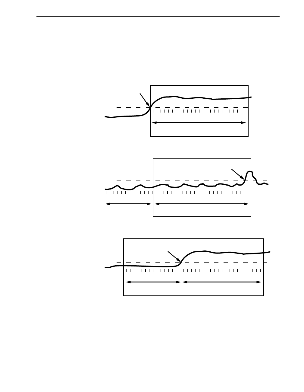
TECHNICAL NOTES
Triggering
Counter timer 1 is programmed with the number of samples
before the trigger (the variable “M”), while counter timer 2 is programmed with the number of samples (variable “N”) after the
trigger.
Figure 7. Post-Trigger Mode
Trigger
Level
4
1 2 3 N
N Samples Total
Figure 8. Pre-Trigger Mode
Trigger
Level
Strawberry Tree
1 2 3 M
4
Discarded Samples
Figure 9. Pre/Post-Trigger Mode
Trigger
Level
1 2 3 M
4
M Samples Before
M Samples Total
1 2 3 N
4
N Samples After
WB-FLASH12 Operator’s Manual
3 – 7
Page 30

WB-FLASH12 OPERATOR’S MANUAL
EDITING
THERMOCOUPLES
STARTING EDITCAL
Using EDITCAL
Using EDITCAL
Your WB-FLASH12 uses an exclusive calibration technology to
achieve great stability, requiring no adjustment for years. (As a
reflection of this, we guarantee the factory tolerances for two years
from the date of purchase.)
Instead of employing adjustment potentiometers to calibrate the
boards, our technicians test and calibrate each WB-FLASH12 after
assembly. That board’s unique calibration number values reside
on-board, in Electrically Erasable Programmable Read Only Memory – EEPROM – chips.
Though recalibration is seldom necessary (and not recommended
CALIBRATION VALUES
unless you have the proper equipment), it may be necessary to
edit calibration numbers to accommodate other changes in your
data acquisition setup. For DOS users, EDITCAL.EXE (or EDITCAL for short) is the utility program that simplifies the modification
of these values. (EDITCAL can be found on the QuickLog PC disk.)
IN DOS
Thermocouple Terminal Panel Calibration –
for thermocouples have thermal isolation blocks and factory calibration for accurate measurements, as the CCAL number on the
label on the panel. CCAL is the value controlling the cold junction compensation temperature.
If you change from one isothermal terminal panel to another , even
if they are the same model number , it might be necessary to enter
a new calibration number (CCAL). Check the calibration value on
the two panels’ labels. If they differ (which is likely), use EDITCAL to change the appropriate value to the new figure.
Similarly, if you are experiencing inaccurate measurements with a
thermocouple, you can use EDITCAL to adjust the CCAL up or
down until the temperature the board reports is correct. (Increasing the CCAL figure by 75 points increases the temperature reading by approximately 1° C.)
For more information, please refer to your terminal panel manual.
Make sure the EDITCAL.EXE program file is in the same subdirectory as the OMEGA Engineering, Inc. application programs.
Load the EDITCAL.EXE program from the keyboard:
Terminal panels suitable
Chapter 3 Technical Notes
3 – 8
Page 31
TECHNICAL NOTES
EDITCAL
Using EDITCAL
SELECTIONS
To Start Up EDITCAL.EXE –
1.
At the DOS prompt, enter EDITCAL, then press the [ENTER]
key. (This invokes the utility.)
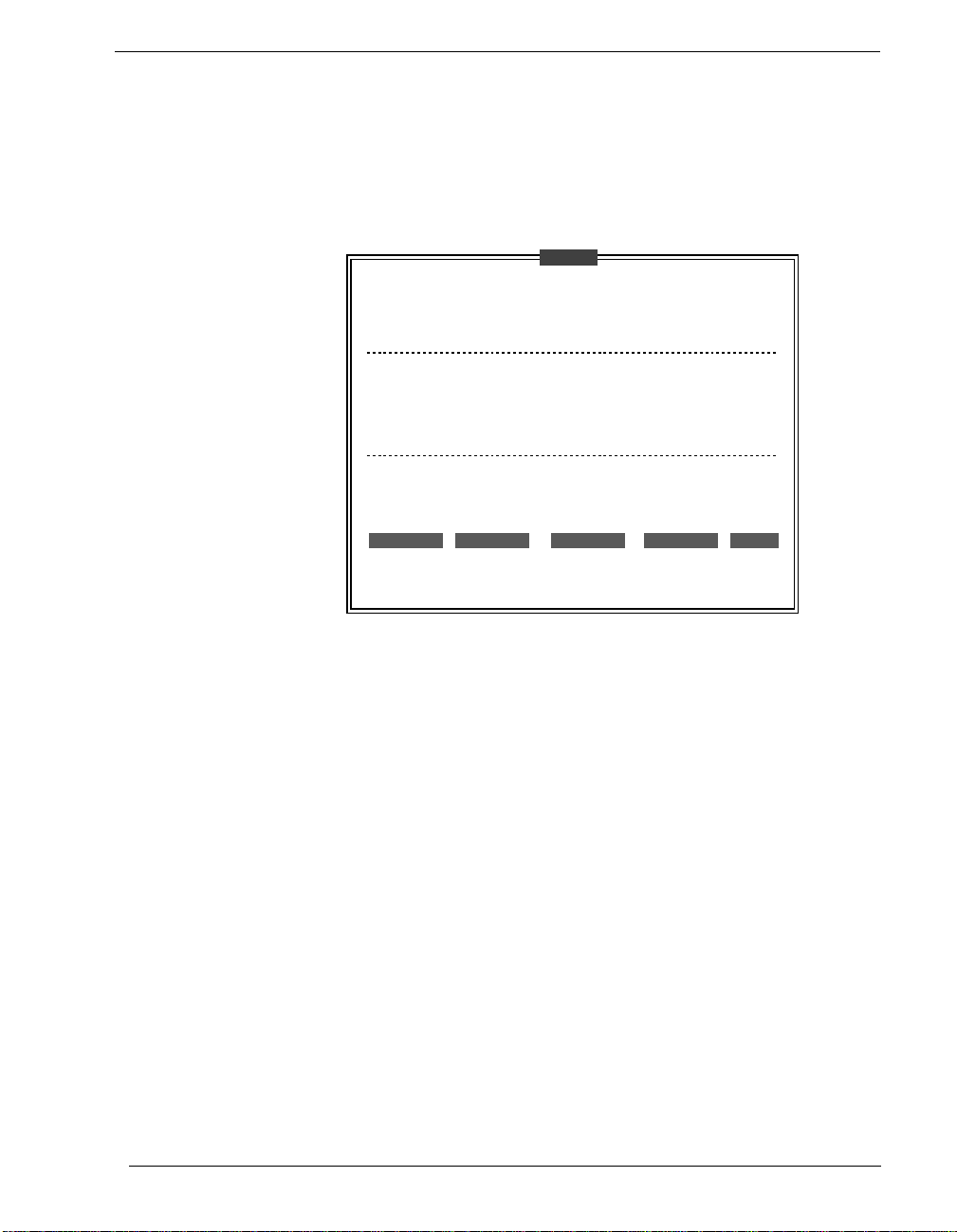
EDITCAL Main Menu –
EDITCAL
CALIBRATION UTILITIES
This program allows for the creation or modification of
calibration data files or hardware EEPROM data on analog
and digital boards. You may create and merge existing
CALIB.DAT or CALOUT.DAT files for multiple boards. You may
update an existing calibration file to add, delete or modify
data. Or you may view or modify EEPROM data or boards.
Do you want to work with calibration data files, view/edit
EEPROM on Analog Connection, highspeed or DATAshuttle boards?
→
use and keys to choose then press ENTER
DATA FILES AC EEPROM HS EEPROM DS EEPROM QUIT
Press the F1 Key at anytime for online help
To Select a Function –
1.
Use the arrow keys to navigate among these menu selections:
→
DATA FILES To merge calibration files supplied from the factory
into a single file for systems that have multiple boards,
or to update existing calibration files.
AC EEPROM To view or modify calibration data on Analog Connec-
tion boards that have non-volatile on-boar d EEPROMS.
HS EEPROMS To view or modify calibration data on high speed
boards EEPROM, such as WB-WORKMATE or WBFLASH12.
DS EEPROMS To view or modify calibration data on DATAshut-
tles’ EEPROM.
QUIT Ends this EDITCAL session.
Strawberry Tree
2.
Move the arrow keys until the selection you want is flashing.
3.
Press [ENTER].
WB-FLASH12 Operator’s Manual
3 – 9
Page 32

WB-FLASH12 OPERATOR’S MANUAL
Changing Hardware Interrupts
Changing Hardware Interrupts
For users of programs such as WorkBench PC for Windows that
employ hardware interrupts, the WB-FLASH12 board provides
for changing the interrupt number, if necessary.
OMEGA Engineering, Inc. customers using DOS have no requirement for this feature, and do not have to change hardware interrupts.
The illustration of the WB-FLASH12 on page 2 – 3 in Chapter 2
identifies the jumper block. (It is labeled as “interrupt jumpers.”)
By repositioning the jumper, which is a plug, to another socket
on the block, you can select another of these interrupts: IRQ2,
IRQ4, IRQ5, IRQ6, or IRQ7.
(Remember that on AT computers the IRQ2 selection is actually
the IRQ9 line.)
Chapter 3 Technical Notes
3 – 10
Page 33

TECHNICAL NOTES
Troubleshooting
Troubleshooting: Installation
If you experience difficulty in getting your data acquisition board
up and running, please check to see that the installation is
according to the descriptions in Chapter 2.
If the software reports a board failure, or that it cannot find a
board, then try these remedies:
1. Confirm that the board is seated properly
(reseat it, if necessary; see the illustration on page 2 – 3).
2. Verify the Board Number switch
2 – 9).
is not set to “0.” (Refer to page
in the PC expansion slot
3. Use a different Base Address.
your installation is trying to use the same Base Address
(please see the explanation on page 2 – 11).
It is possible that another device in
4. If there is more than one OMEGA data acquisition board in your installation
, make sure they all have the same Base Address, but dif-
ferent Board Numbers.
5. Install the board in another open slot
tions on page 2 – 5).
6. Remove other devices
whether or not they are conflicting with your data acquisition
board.
from expansion slots in your PC to check
7. If possible, install the board in another computer
operation.
8. Verify that the software is up to date
the board you are using. Contact us, or your software provider).
9. Remove other terminate and stay resident (TSR)
your system’s AUTOEXEC.BAT file, temporarily.
10. Replace the Z8536 chip
our Technical Services department for testing.
(Please call our Technical Support line before returning a board – we
hope to assist you with your problem via telephone.)
on the board, or return the product to
in the PC (follow the instruc-
to verify its correct
(a version compatible with
programs from
Strawberry Tree
WB-FLASH12 Operator’s Manual
3 – 11
Page 34

WB-FLASH12 OPERATOR’S MANUAL
HINTS
OPERATING
Troubleshooting
Troubleshooting: Operation
During operation, it’s good practice to short all analog input
channels you’re not using; to do this, connect + to – to Com.
It’s essential to have exactly one ground reference per channel.
This single connection to ground makes sure you don’t exceed
the common mode range of input.
(More than one connection per channel can lead to ground loops,
causing errors or erratic readings. Connecting the – to the Com
terminal provides a single ground. Your sensor might also provide another ground. If you’re not sure that your sensor is
grounded, try connecting the – to Com, and not, and see which
works best.)
Here are mini “case studies” of difficulties, along with some easy
Qs AND As
solutions:
Problem: I read a voltage with my multimeter at the analog input termi-
nals, with nothing connected.
Action:
None. Any voltage between – 12V and + 12V is possible,
when nothing is connected.
Problem: My board reads analog input wrong.
Try shorting + to – to Com: the board should return a
Action:
reading around 0V.
Chapter 3 Technical Notes
3 – 12
Problem: My board reads the thermocouple as a very negative tempera-
ture.
Verify the connections are secure. Opens read as negative
Action:
temperature.
Problem: My board reads thermocouple input wrong.
Using EDITCAL, confirm that the CCAL number matches
Action:
the number on the terminal panel’s calibration label (see
pages 3–8 through 3–9).
(If you need to use a general purpose terminal panel – one
that doesn’t have a factory CCAL number – with a thermocouple, you can achieve approximate results by entering a CCAL of 2300. Then change the figure by about 75
points for each degree C. that you want to raise the temperature.)
Page 35

IF YOU NEED
CUSTOMER SUPPORT
TECHNICAL NOTES
Troubleshooting
Problem: My board used to work, but now the software cannot find it, or
reports an error.
Action:
Check to make sure the Board Number switch is not set to
“0.”
What to do before calling technical support, to help us serve you better:
Have the part numbers of your boards and terminal panels
1.
ready.
2.
Have the type and version number of the software you’re
using.
3.
Have your computer’s type, model, and the version of the
operating system.
Strawberry Tree
WB-FLASH12 Operator’s Manual
3 – 13
Page 36
WB-FLASH12 OPERATOR’S MANUAL
ANALOG INPUT
ACCURACY
Product Specifications
Specifications of the WB-FLASH12
The WB-FLASH12 has 16 available analog inputs when set to single-ended mode; eight analog inputs are available in differential
mode. (See page 2–13 for instructions on setting the Analog Input
Mode.)
Analog Input Memory –
board (DB03-M), the WB-FLASH12 features analog input memory of up to one million samples.
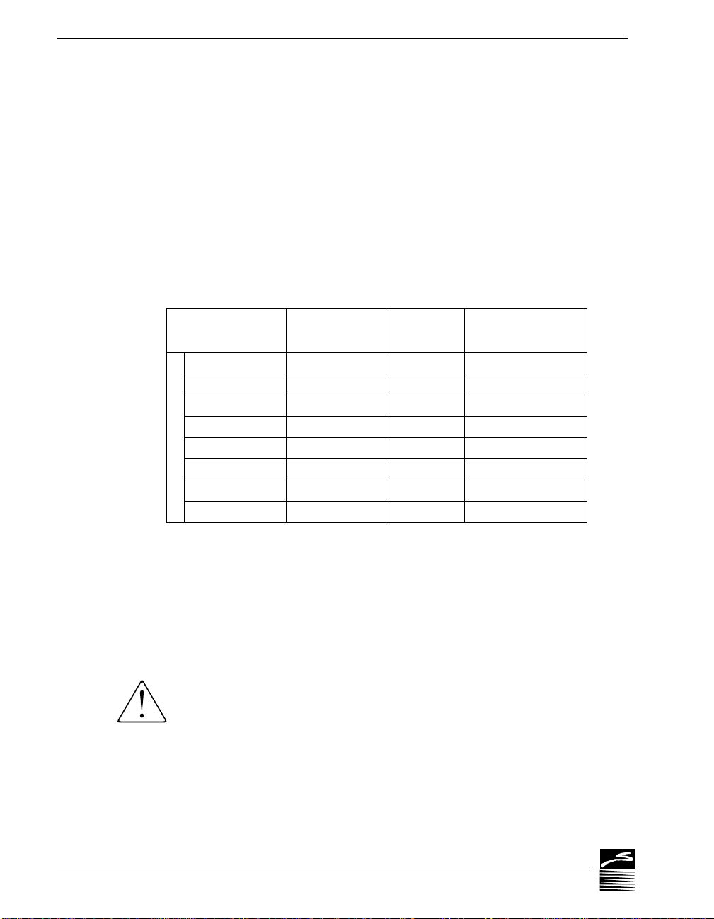
WB-FLASH12* GENERAL CONDITIONS ACCURACY –
When installed with the optional daughter-
Unipolar Full
Scale Range
†
Bipolar Full
Scale Range
†
Resolution
Accuracy
(% of full scale)
N/A ± 10V 4.88mV ± 4mV (.02%)
0 to 10V ± 5V 2.44mV ±5mV(.05%)
0 to 5V ± 2.5V 1.22mV ± 2.5mV (.05%)
0 to 2 V ± 1V 488µV ± 1mV (.05%)
0 to 1V ± 500mV 244µV ± 0.75mV (.075%)
VOLTAGE
0 to 500mV ± 250mV 122µV ± 0.375mV (.075%)
0 to 200mV ± 100mV 48.8µV ± 0.2mV (.1%)
0 to 100mV ± 50mV 24.4µV ± 0.1mV (.1%)
*The WB-FLASH12 Model 2 only supports the Bipolar Range
±5V.
†
Due to automatic calibration, actual maximum and minimum
voltage can be 1.5% above or below the stated value.
General Conditions –
12-bit (0.024%) resolution, after automatic
self-calibration. From 15°C to 35°C at the interface board. Source
resistance less than 1k Ohms. Includes linearity, drift, offset, and
calibration errors.
WB-FLASH12 RTD ACCURACY –
W e do not r ecommend using the WB-FLASH12 for R TD or strain
gauge measurements. The reference voltage does not supply
enough current to accurately support these type of measurements.
Chapter 3 Technical Notes
3 – 14
Page 37

TECHNICAL NOTES
Product Specifications
WB-FLASH12 THERMOCOUPLE ACCURACY –
Type Range (°C.)
-100 to 880 0.6 0.15 ± 3
J
12-Bit
Resolution (°C)
-210 to -100 1.0 0.25 ± 6
K
-75 to 1370 0.6 0.15 ± 3
-260 to -75 0.8 to 8 0.2 to 2 ± 4 to 35
0 to 1000 0.4 0.1 ± 2.5
E
-200 to 0 0.5 to 1 0.125 to 0.25 ± 5
-270 to -200 1 to 6 0.25 to 1.5 ± 5 to 30
0 to 400 0.6 0.15 ± 3
T
-200 to 0 0.6 to 1 0.15 to 0.25 ± 3 to 6
-270 to -200 1 to 6 0.25 to 1.5 ± 6 to 30
S
0 to 300 3 to 5 0.75 to 1.25 20
300 to 1770 2 to 3 0.5 to 0.75 12
R
0 to 200 3 to 5 0.75 to 1.25 20
200 to 1770 2 to 3 0.5 to 0.75 12
200 to 400 6 to 12 1.5 to 3.0 50
B
400 to 800 3 to 6 0.75 to 1.5 25
800 to 1820 2 to 3 0.5 to 0.75 13
G
25 to 200 3 to 12 0.75 to 3 50
200 to 2315 2 to 3 0.5 to 0.75 15
D
-20 to 2315 1.7 to 3 0.4 to 0.75 12
C
-20 to 2315 1.5 to 3 0.38 to 0.75 12
N
-100 to 200 0.8 to 1.3 0.2 to 0.3 ± 5
200 to 1300 0.8 0.2 ± 3
14-Bit
Resolution (•C)
Accuracy
(°C.)
Strawberry Tree
Thermocouple Conditions –
Same as General Conditions. Does not
include the accuracy of the thermocouple itself (cold junction
error must be added in; cold junction compensation with T21
terminal panel only; please see your terminal panel manual’s
specifications for cold junction compensation error). Accuracy is
approximate because resolution varies with temperature.
Thermocouples use the 50 mV range. For inputs below -5 mV
(below approximately -100 degrees C.) use the +/-25 mV range.
For the best resolution use the 50 mV range above -5 mV.
WB-FLASH12 Operator’s Manual
3 – 15
Page 38

WB-FLASH12 OPERATOR’S MANUAL
INPUT IMPEDANCE
NOISE REJECTION
COMMON MODE RANGE
INPUT PROTECTION
RESOLUTION/
Product Specifications
All analog inputs have an impedance rating of >100gΩ.
CMRR –
Conditions for Common Mode Rejection Ratio (CMRR):
DC to 1k Hz, common mode input. This specification applies
even when one or more nonmeasured channels exceeds the operating common mode range.
SCAN RATE
WB-FLASH12 NOISE REJECTION –
Unipolar
Range
Bipolar
Range
CMRR
Typical Internal Noise
(RMS)
N/A ± 10V > 86 dB 5 mV
0 to 10V ± 5V > 86 dB 2.5 mV
0 to 5V ± 2.5V > 86 dB 1.25 mV
0 to 2 V ± 1V > 86 dB 1.25 mV
0 to 1V ± 500mV > 92 dB 600 µV
0 to 500mV ± 250mV > 98 dB 300 µV
0 to 200mV ± 100mV > 98 dB 300 µV
0 to 100mV ± 50mV > 98 dB 300 µV
No input may exceed ± 10.5 Volts.
Operating –
Nonoperating –
± 30 Volts, maximum.
± 20 Volts, maximum.
Selectable in software:
WB-FLASH12 RESOLUTION AND SCAN RATE* –
Model 1 Scan Rate Model 2 Scan Rate
Resolution
Single
Channel
Multiple
Channels
†
Single
Channel
Multiple
Channels
†
Chapter 3 Technical Notes
3 – 16
14 bits: 0.006% 250 kHz 250 kHz 62.5 kHz 400 kHz
13 bits: 0.012% 500 kHz 500 kHz 250 kHz 100 kHz
12 bits: 0.024% 1 MHz 1 MHz 1 MHz 25 kHz
* Burst mode. Rate with continuous sampling will be lower.
† Divide this rate by the number of channels in use.
NOTE: For the Model 1 boards, multiple scan rate can differ
according to the range in use. See table on next page.
Page 39

TECHNICAL NOTES
DIGITAL I/O
COUNTER/TIMER
TRIGGER INPUT
Product Specifications
CHANNELS
Scan Rate –
Scan rate is the rate in Hertz (or, samples per second)
to read data into memory, including the time it takes to switch
channels and ranges. To calculate the total scan time for all channels, divide the rate by the number of channels.
(After placing a burst of data into memory, and depending on
your computer and software, the system requires additional processing time before the data are available to you, or before you
can collect more data.)
WB-FLASH12 MODEL 1 SCAN RATE* BY RANGE –
Unipolar
Range
Bipolar
Range
Multi-Channel
Scan Rate
N/A ±10V 1 MHz
0 to 10V ±5V 1 MHz
0 to 5V ±2.5V 750 kHz
0 to 2 V ±1V 600 kHz
0 to 1V ±500mV 750 kHz
0 to 500mV ±250mV 1 MHz
0 to 200mV ±100mV 1 MHz
0 to 100mV ±50mV 1 MHz
* Fixed range. When range is changed, rate can be as low as
400kHz on 1V/—500mV or smaller ranges. Divide the rate by 4
for 13-bit resolution, by 16 for 14-bit. Scan rate settle to .25%.
The WB-FLASH12 has 8 digital I/O lines, with each line individually selectable as input or output. Inputs are 5 Volt TTL-compatible.
Strawberry Tree
Their outputs are also 5 Volt TTL-compatible, or high voltage
open collector on the terminal panel.
(Please see the specifications in your terminal panel owner’s manual.)
The WB-FLASH12 has one on-board 16-bit counter/timer with a
2 MHz internal clock. The counter timer is connected to Digital I/
O lines 5 through 8.
The WB-FLASH12 has one digital trigger input, positive or negative slope, TTL-compatible.
The analog trigger input, positive or negative slope, features a
trigger range of -10 to 10V in 256 steps.
WB-FLASH12 Operator’s Manual
3 – 17
Page 40
WB-FLASH12 OPERATOR’S MANUAL
ANALOG OUTPUT
PHYSICAL
PHYSICAL
GENERAL
Product Specifications
When installed with the optional daughterboard (DB03-M) the
WB-FLASH12 features two analog outputs. The daughterboard
comes equipped with a dual 256K analog output buffer.
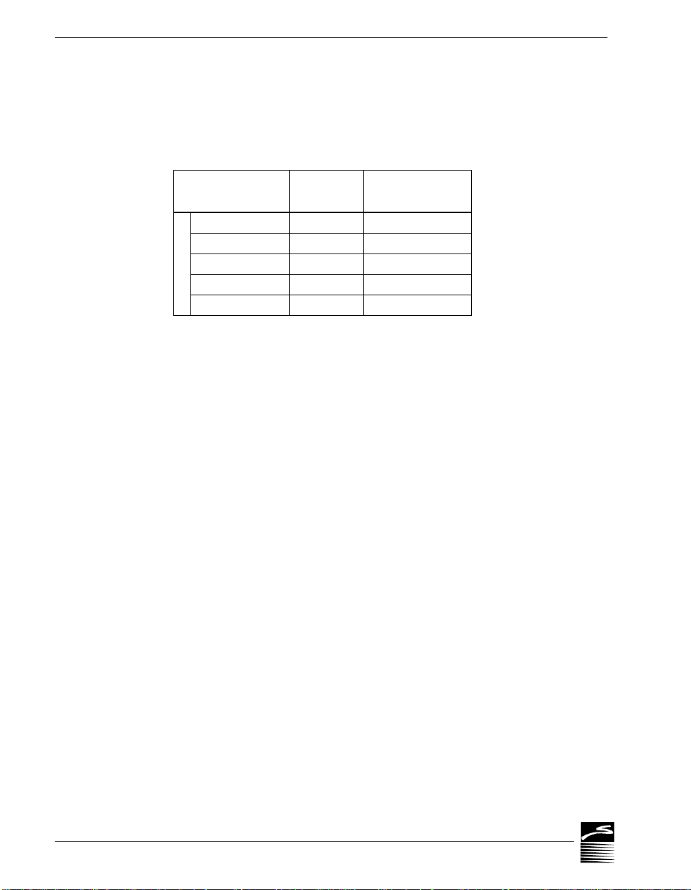
DB03-M ANALOG OUTPUT RANGES/ACCURACY –
Full Scale
Range
Voltage
Resolution
Accuracy
(% of full scale)
0 to 10V 2.44mV ± 3mV(.03%)
± 10V 2.44mV ± 6mV (.03%)
0 to 5V 1.22mV ± 3.5mV (.07%)
± 5V 1.22mV ± 7mV (.07%)
VOLTAGE
± 2.5V 666µV ± 5mV (.10%)
General Conditions –
12-bit (0.024%) resolution. Includes linearity,
offset, and initial calibration.
Speed –
1 MHz analog output rate using output memory buffer
(not supported by all software); 10 to 90% Rise Time, 3µs.
Output Protection –
May be shorted to any voltage between -12V
and 12V.
Output Impedance –
Output Current –
<0.5Ω.
±5mA minimum.
Stability of the Analog Outputs–
· Response time to 0.1% accuracy:
<8µs, 10V step
<3µs, 1% of full scale step
· Temperature drift: <0.004% per degree Celsius, maximum.
DIMENSIONS
DIMENSIONS
CONDITIONS
Chapter 3 Technical Notes
3 – 18
The WB-FLASH12 is a full-size PC board measuring 13.0" by
4.2" (33.0cm by 10.7cm).
The optional daughterboard (DB03-M) measures 7.6" by 3.9"
(19.3cm by 9.9cm).
Auxiliary Power Output –
+5v, +12V, or -12V, direct from the com-
puter’s power supply, unfused. It is not to exceed 1A.
Reference Voltage Output –
Operating Temperature Ambient –
6.667V, ±1%; 1kΩ output impedance.
0 to 50 degrees Celsius.
Page 41

TECHNICAL NOTES
Typical Current Consumption –
WB-FLASH12 Setup + 5V + 12V - 12V
No Daughterboard 1,200 mA 150 mA 150 mA
With DBO3-M* 1,400 mA 250 mA 175 mA
* No load on analog outputs.
Product Specifications
Strawberry Tree
WB-FLASH12 Operator’s Manual
3 – 19
Page 42

WB-FLASH12 OPERATOR’S MANUAL
Chapter 3 Technical Notes
3 – 20
 Loading...