

Page 1

USER’S GUIDE
UFM Vane/Piston Consolidated
User’s Manual
dwyer-inst.com | [email protected]
For latest product manuals:
dwyer-inst.com/en/instruction-manuals
Bulletin F-PI
Page 2

CONTACT
Dwyer Instruments, LLC
dwyer-inst.com/en/contact-us
Toll-Free:
1-800-872-9141
Telephone:
(219) 879-8000
Fax:
(219) 872-9057
Email: [email protected]
(USA only)
Page 3

Table of Contents
1. A, L, Z General Vane / Piston Switch Manual ..............................................................................................................6
1.1. Name Plates and Product ID ........................................................................................................................................6
1.2. Installation ............................................................................................................................................................................7
1.3. Electrical Switch Ratings ................................................................................................................................................8
2. Vane/Piston H0 - Transmitter with HART ........................................................................................................................9
2.1. Quick Set Up .......................................................................................................................................................................9
2.1.1. Wiring Using Pre-Installed Wires: .......................................................................................................................9
2.1.2. Wiring Removing Pre-Installed Wires: ..............................................................................................................9
2.2. Introduction to HART® Field Device Specifications .............................................................................................. 10
2.2.1. Scope ...............................................................................................................................................................................10
2.2.2. Purpose ..........................................................................................................................................................................10
2.2.3. Who Should Use this Document? .........................................................................................................................10
2.2.4. Abbreviations and Definitions ................................................................................................................................10
2.3. Process Interface ...............................................................................................................................................................10
2.3.1. Magnetic Sensors ........................................................................................................................................................10
2.3.2. Host Interface Analog Output 1: Process Flow ...............................................................................................11
2.4. Dynamic Variables ............................................................................................................................................................11
2.5. Status Information .............................................................................................................................................................11
2.5.1. Additional Device Status (Command #48) ........................................................................................................12
2.5.2. Burst Mode .....................................................................................................................................................................12
2.5.3. Catch Device Variable ..............................................................................................................................................12
2.6. Device-Specific Commands ..........................................................................................................................................12
2.7. Command #128: Read Alarm Setpoints ...................................................................................................................12
2.7.1. Request Data Bytes ....................................................................................................................................................12
2.7.2. Response Data Bytes ................................................................................................................................................12
2.8. Command #129: Write Low Alarm Setpoint ............................................................................................................13
2.8.1. Request Data Bytes ....................................................................................................................................................13
2.8.2. Response Data Bytes ................................................................................................................................................13
2.8.3. Command-Specific Response Codes .................................................................................................................13
2.9. Command #131: Reset Totalizer ..................................................................................................................................13
2.9.1. Request Data Bytes ....................................................................................................................................................13
2.9.2. Response Data Bytes ................................................................................................................................................13
2.9.3. Command-Specific Response Codes .................................................................................................................14
2.10. Performance ........................................................................................................................................................................14
2.10.1. Sampling Rates ............................................................................................................................................................14
2.10.2. Power-Up ........................................................................................................................................................................14
2.10.3. Reset .................................................................................................................................................................................14
2.10.4. Self-Test ...........................................................................................................................................................................14
2.10.5. Command Response Times ....................................................................................................................................14
2.11. Capability Checklist..........................................................................................................................................................15
3. Vane/Piston - XØ Transmitter .............................................................................................................................................16
3.1. Nameplates and Product ID ..........................................................................................................................................17
4. Vane/Piston RX/RH ..................................................................................................................................................................18
4.1. Installation ............................................................................................................................................................................21
3Table of Contents
Page 4

4.2. References ............................................................................................................................................................................21
4.3. Device Identification .........................................................................................................................................................21
4.4. Product Overview ..............................................................................................................................................................22
4.5. Process Interface ...............................................................................................................................................................22
4.5.1. Magnetic Sensors ........................................................................................................................................................22
4.5.2. Host Interface: Process Flow ..................................................................................................................................22
4.6. Status Information .............................................................................................................................................................23
4.6.1. Extended Device Status............................................................................................................................................23
4.7. Universal Commands .......................................................................................................................................................24
4.8. Common-Practice Supported Commands...............................................................................................................24
4.8.1. Command-Specific Response Codes .................................................................................................................24
4.9. Command #130: Write High Alarm Setpoint ...........................................................................................................24
4.9.1. Request Data Bytes ....................................................................................................................................................24
4.9.2 . Response Data Bytes ................................................................................................................................................24
4.9.3. Command-Specific Response Codes .................................................................................................................25
4.10. Tables ....................................................................................................................................................................................25
4.10.1. Flow Unit Codes ..........................................................................................................................................................25
4.10.2. Unit Conversion ............................................................................................................................................................25
4.11. Performance ........................................................................................................................................................................25
4.11.1. Busy and Delayed-Response .................................................................................................................................25
4.11.2. Long Messages ............................................................................................................................................................25
4.11.3. Non-Volatile Memory .................................................................................................................................................25
4.11.4. Modes ..............................................................................................................................................................................25
4.11.5. Write Protection ...........................................................................................................................................................26
4.11.6. Damping .........................................................................................................................................................................26
4.12. Default Configuration .......................................................................................................................................................26
5. Vane/Piston - TX Transmitter / TH Transmitter with HART ......................................................................................27
5.1. Installation ............................................................................................................................................................................30
5.2. Device Identification .........................................................................................................................................................30
5.3. Product Overview ..............................................................................................................................................................30
5.4. Process Interface ...............................................................................................................................................................31
5.4.1. Magnetic Sensors ........................................................................................................................................................31
5.4.2. Host Interface: Process Flow ..................................................................................................................................31
5.5. Status Information .............................................................................................................................................................32
5.5.1. Extended Device Status............................................................................................................................................32
5.6. Universal Commands .......................................................................................................................................................32
5.7. Common-Practice Supported Commands...............................................................................................................32
5.7.1 . Burst Mode .....................................................................................................................................................................32
5.7.2. Catch Device Variable ..............................................................................................................................................32
5.8. Device-Specific Commands ..........................................................................................................................................33
5.9. Command #129: Write Low Alarm Setpoint ............................................................................................................33
5.9.1. Request Data Bytes ....................................................................................................................................................33
5.9.2. Response Data Bytes ................................................................................................................................................33
5.9.3. Command-Specific Response Codes .................................................................................................................33
5.10. Command #131: Reset Totalizer ..................................................................................................................................33
4 UFM Vane Piston Consolidated Manual
Page 5

5.10.1. Request Data Bytes ....................................................................................................................................................33
5.10.2. Response Data Bytes ................................................................................................................................................34
5.10.3. Command-Specific Response Codes .................................................................................................................34
5.11. Performance ........................................................................................................................................................................34
5.11.1. Sampling Rates ............................................................................................................................................................34
5.11.2. Power-Up ........................................................................................................................................................................34
5.11.3. Reset .................................................................................................................................................................................34
5.11.4. Self-Test ...........................................................................................................................................................................34
5.11.5. Command Response Times ....................................................................................................................................34
5.12. Capability Checklist..........................................................................................................................................................35
6. Vane/Piston TXL ........................................................................................................................................................................36
6.1. Name Plate and Product ID ..........................................................................................................................................36
6.2. Set Low Flow Alarm .......................................................................................................................................................... 38
7. Device Dimension Drawings.................................................................................................................................................39
8. Compliance and Certifications ............................................................................................................................................45
5Table of Contents
Page 6

1. A, L, Z General Vane / Piston Switch Manual
Installation and Operation Manual for series: PI, LL, LP, LH, SN, SM, SH, MN, MM, MH, SX and MX for A, L or Z
control boxes with 0, 1 or 2 switches.
1.1. Name Plates and Product ID
This manual applies to all vane/piston meters that have one of the designators in the model codes shown in
the table shown below. This can be seen on the name plate example.
Model Code Designations for Zero, One,
and Two Switches
4 to 20 mA transmitter (intrinsically safe
with approved barriers)
HART with programmable switch points AH0 LH0 ZH0
Display only A0 L0 Z0
One SPDT (3 wire) A1 L1 Z1
One high vibration SPDT (3 wire) A1B L1B Z1B
Two SPDT (3 wire) A2 L2 Z2
Two high vibration SPDT (3 wire) A2B L2B Z2B
One SPDT (4 wire) A3 L3 Z3
Two SPDT (4 wire) A4 L4 Z4
One SPDT (3 wire) hermetically sealed A53 L53 Z53
Two SPDT (3 wire) hermetically sealed A54 L54 Z54
One SPDT (3 wire) high temperature A61 L61 Z61
Two SPDT (3 wire) high temperature A62 L62 Z62
One SPDT (3 wire) gold contact A71 L71 Z71
Two SPDT (3 wire) gold contact A72 L72 Z72
Polysulfone Aluminum 316 SS
AX0 LX0 ZX0
Figure 1: Name Plate example
6 UFM Vane Piston Consolidated Manual
Page 7

1.2. Installation
For best results, the meters may be installed in any position as long as proper piping installation requirements
are observed. This includes sufcient support of adjacent piping to minimize the system’s inherent vibration.
Unions of the same pipe size and full
port isolation ball valves may be installed
for ease of removal and servicing of
equipment, if necessary.
Wire directly to the switch terminal screws.
In One Switch units, the cam is easily
adjusted by depressing the outer ring and
turning it to the desired position.
Figure 2: Device overview
Figure 3: Cam adjustment
7A, L, Z General Vane / Piston Switch Manual
Page 8

WARNING: This instrument was made for the specic use stated at the time of order. Any other use may
cause injury. Read instructions before using the device.
Supply Connections—Wire Sizes: Wire used to connect any Switches included must be in accordance with
all local and national codes. Wire size and insulation ratings should support actual loads. See also Switch
Ratings below. In all cases, wire must be, as a minimum, 20 AWG Teon insulated rated at 600V and 200°C. It
is recommended to include a disconnect switch or circuit breaker near this equipment.
1.3. Electrical Switch Ratings
Switch Identication Switch Description Electrical Ratings
UFM P/N-704CE, 704CE-P4, 704CE P5
Model Code Designator: 1 or 2
UFM P/N-986CE
Model Code Designator: 1B or 2B
UFM P/N-702
Model Code Designator: 61 or 62
UFM P/N-808
Model Code Designator: 71 or 72
UFM P/N-703
Model Code Designator: 3 or 4
SPDT – (3 wire)
(1 or 2 switches may
be provided)
SPDT – (3 wire)
High Vibration
SPDT –
High Temperature
SPDT –
Gold Contact
SPDT – (4 wire)
Single-Break Form Z
15 A – 125 V AC, 250 V AC, 480 V AC; HP
– 125 V AC, ¼ HP – 250 V AC
20 A – 125 V AC, 250 V AC, 480 V AC; ½
A – 125 V DC, ¼A -250 V DC; 1 HP – 125 V
AC, 2 HP – 250 V AC
15 A – 125 V AC, 250 V AC, 480 VAC; ½ A –
125 V DC, ¼ A -250 V DC; HP – 125 V AC,
¼ HP – 250 V AC
15 A – 125 V AC, 250 V AC, 480 V AC; HP
– 125 V AC, ¼ HP – 250 V AC
15 A – 125 V AC, 250 V AC, 480 V AC; 1 A
– 125 V DC, ½ A -250 V DC; ¼ HP – 125 V
AC, ½ HP – 250 V AC
8 UFM Vane Piston Consolidated Manual
Page 9

2. Vane/Piston H0 - Transmitter with HART
Installation and Operation Manual Series: PI, LL, LP, LH, SN, SM, SH, MN, MM, MH, SX and MX used with control
boxes: A, L, or Z with 4 to 20 mA transmitter with HART.
2.1. Quick Set Up
2.1.1. Wiring Using Pre-Installed Wires:
Complete the loop circuit using the 2 pre-installed 18”, 22 AWG wires provided.
Important: Observe polarity—The red wire is positive (+), and the black wire is negative (-).
2.1.2. Wiring Removing Pre-Installed Wires:
Open cover and remove pre-installed wires. Connect a twisted wire pair (not provided) to the terminals
observing the polarity marked on the PC board. The units are shipped with a red wire connected to the
positive (+) terminal, and a black wire connected to the negative (-) terminal. The wire may be up to AWG
14 size, but no smaller than AWG 22.
Figure 4: Terminals for 4 to 20 mA loop
9Vane/Piston H0 - Transmitter with HART
Page 10

2.2. Introduction to HART® Field Device Specifications
2.2.1. Scope
The Universal Flow Monitors water ow transmitter, model ME Transmitter complies with HART Protocol
Revision 7.0. This document species all the device specic features and documents HART Protocol
implementation details (e.g., the Engineering Unit Codes supported). The functionality of this Field Device
is described sufciently to allow its proper application in a process and its complete support in HART
capable Host Applications.
2.2.2. Purpose
This specication is designed to complement other documentation (e.g., the installation manuals specic
to PI, LL, LP, LH, SN, SM, SH, MN, MM, MH, SX, MX, LN, LE, and XHF model ow meters) by providing a
complete, unambiguous description of this Field Device from a HART Communication perspective.
2.2.3. Who Should Use this Document?
The specication is designed to be a technical reference for HART capable Host Application Developers,
System Integrators and knowledgeable End Users. It also provides functional specications (e.g.,
commands, enumerations and performance requirements) used during Field Device development,
maintenance and testing. This document assumes the reader is familiar with HART Protocol requirements
and terminology.
2.2.4. Abbreviations and Definitions
ADC Analog to Digital Converter
CPU Central Processing Unit (of microprocessor)
DAC Digital to Analog Converter
EEPROM Electrically-Erasable Read-Only Memory
ROM Read-Only Memory
PV Primary Variable
SV Secondary Variable
HCF HART Communication Foundation
FSK Frequency Shift Keying Physical Layer
2.3. Process Interface
2.3.1. Magnetic Sensors
There are two built-in hall-effect sensors measuring the rotation of a permanent magnet that is mounted
onto the owmeter shaft. As the shaft rotates with ow, the sensors provide analog readings that are
in turn converted to a digital value by and A/D converter. The digital values are then processed by the
microcontroller and linearized, and subsequently converted to a scaled analog output via a D/A converter
in the range of 4 to 20 mA.
10 UFM Vane Piston Consolidated Manual
Page 11

2.3.2. Host Interface Analog Output 1: Process Flow
The two-wire 4 to 20 mA current loop is connected to two terminals on the transmitter circuit board.
Depending on the product used, one of the two congurations are offered for eld wiring.
The rst option allows the user to directly connect the loop wires to the terminals on the PCB. The correct
polarity is shown in the pictures below, where the red wire is connected to the (+) terminal and the black
wire is connected to the (–) terminal.
Figure 5: PCB Polarity wiring
2.4. Dynamic Variables
Two Dynamic Variables are implemented.
PV Volumetric Flow Reading GPM, CMH, LPM
SV Totalizer Value based on PV Follows PV Units
The PV is derived using a calibrated linearization table applied to A/D converter readings of hall-effect
sensors. The SV is based on a 5ms timer and is updated based on the current reading of ow. Both PV and
SV values are smoothed.
2.5. Status Information
Bit Mask Denition Conditions to set bit
0x80(bit 7) Device Malfunction None
0x40(bit 6) Conguration Changed Any change in device conguration
0x20(bit 5) Cold start Set any time power is cycled
0x10(bit 4) More Status Available Triggers when either alarm is active
0x08(bit 3) Loop Current Fixed None
0x04(bit 2) Loop Current Saturated Occurs when loop current reaches upper limit
0x02(bit 1) Non-Primary Variable out of limits None
0x01(bit 0) Primary Variable Out of limits
When Bit 4 is set, Host should send Command 48 to determine which alarm is active.
Meaning Units
Occurs when PV is being limited due to
exceeding calibrated limitations
11Vane/Piston H0 - Transmitter with HART
Page 12

2.5.1. Additional Device Status (Command #48)
Command #48 returns 9 bytes of data, with the following status information:
Bit Mask Description Conditions
0x80 Undened NA
0x40 Undened NA
0x20 Undened NA
0x10 Undened NA
0x08 Undened NA
0x04 Undened NA
0x02 High Alarm High Alarm is active if set
0x01 Low Alarm Low Alarm is active if set
2.5.2. Burst Mode
This Field Device does not support Burst Mode.
2.5.3. Catch Device Variable
This Field Device does not support Catch Device Variable.
2.6. Device-Specific Commands
The following device-specic commands are implemented:
128 Read Alarm Setpoints
129 Write Low Alarm Setpoint
130 Write High Alarm Setpoint
131 Reset Totalizer
2.7. Command #128: Read Alarm Setpoints
Reads the High and Low Alarm Setpoints. If zero, the alarm is disabled.
2.7.1. Request Data Bytes
Byte Format Description
None
2.7.2. Response Data Bytes
Byte Format Description
0 Enum PV Unit value
1-4 Float High Alarm Setpoint
5-8 Float Value of High Alarm Setpoint
12 UFM Vane Piston Consolidated Manual
Page 13

2.8. Command #129: Write Low Alarm Setpoint
Writes the setpoint for the Low Alarm.
2.8.1. Request Data Bytes
Byte Format Description
0-3 Float Low Alarm Setpoint
2.8.2. Response Data Bytes
Byte Format Description
0 Enum PV Unit value
1-4 Float Low Alarm Setpoint
2.8.3. Command-Specific Response Codes
Code Class Description
0 Success No Command-Specic Errors
1-15 Undened
16 Error Access Restricted
17-31 Undened
32 Error Busy
33 -127 Undened
2.9. Command #131: Reset Totalizer
Resets the totalizer to zero.
2.9.1. Request Data Bytes
Byte Format Description
None
2.9.2. Response Data Bytes
Byte Format Description
None
13Vane/Piston H0 - Transmitter with HART
Page 14

2.9.3. Command-Specific Response Codes
Code Class Description
0 Success No Command-Specic Errors
1-15 Undened
16 Error Access Restricted
17-31 Undened
32 Error Busy
33 -127 Undened
2.10. Performance
2.10.1. Sampling Rates
Typical sampling rates are shown in the following table.
PV digital value calculation 10 per second
SV digital value calculation 10 per second
Analog output update 10 per second
2.10.2. Power-Up
The device is typically ready within 1 second of power-up. Totalizer is initialized to zero.
2.10.3. Reset
Command 42 (“Device Reset”) causes the device to reset its microcontroller. The resulting restart is
identical to the normal power up sequence.
2.10.4. Self-Test
Self-Test is not supported.
2.10.5. Command Response Times
Minimum 20 ms
Typ ical 50 ms
Maximum 100 ms
14 UFM Vane Piston Consolidated Manual
Page 15

2.11. Capability Checklist
Manufacturer, model and revision Universal Flow, ME Transmitter, Rev1
Device type Transmitter
HART revision 7.0
Device Description available No
Number and type of sensors 2 internal
Number and type of actuators 0
Number and type of host side signals 1: 4 to 20 mA analog
Number of Device Variables 4
Number of Dynamic Variables 2
Mappable Dynamic Variables? No
Number of common-practice commands 5
Number of device-specic commands 4
Bits of additional device status 2
Alternative operating modes? No
Burst mode? No
Write-protection? No
15Vane/Piston H0 - Transmitter with HART
Page 16

3. Vane/Piston - XØ Transmitter
Installation and Operation Manual Series: PI, LL, LP, LH, SN, SM, SH, MN, MM, MH, SX, MX, LN, LE, and XHF control
boxes with transmitter. The AX0, LX0, and ZX0 are display and transmitter only. They do not contain internal
switches and are intrinsically safe when used with approved barriers.
Model Code Designations for Zero, One,
and Two Switches
4 to 20 mA transmitter (intrinsically safe
with approved barriers)
HART with programmable switch points AH0 LH0 ZH0
Display only A0 L0 Z0
One SPDT (3 wire) A1 L1 Z1
One high vibration SPDT (3 wire) A1B L1B Z1B
Two SPDT (3 wire) A2 L2 Z2
Two high vibration SPDT (3 wire) A2B L2B Z2B
One SPDT (4 wire) A3 L3 Z3
Two SPDT (4 wire) A4 L4 Z4
One SPDT (3 wire) hermetically sealed A53 L53 Z53
Two SPDT (3 wire) hermetically sealed A54 L54 Z54
One SPDT (3 wire) high temperature A61 L61 Z61
Two SPDT (3 wire) high temperature A62 L62 Z62
One SPDT (3 wire) gold contact A71 L71 Z71
Two SPDT (3 wire) gold contact A72 L72 Z72
Polysulfone Aluminum 316 SS
AX0 LX0 ZX0
16 UFM Vane Piston Consolidated Manual
Page 17

3.1. Nameplates and Product ID
This manual applies to all vane/piston meters that have the designator “AX0”, “LX0” or “ZX0” in the model
code. This can be seen on the name plate as shown below.
Figure 6: Name plate and Product ID
17Vane/Piston - XØ Transmitter
Page 18

4. Vane/Piston RX/RH
Installation and Operation Manual Series: PI, LL, LP, LH, SN, SM, SH, MN, MM, MH, SX, MX, LN, LE and XHF Used
with R control boxes with 4 to 20 mA transmitter or HART and optional mechanical switches. The RX0 is display
and transmitter only. The RX0 does not contain any internal switches and is intricisically safe when used with
approved barriers.
Flow rate display, hazardous location
switches as follows:
One SPDT hazardous location R7*
One DPDT hazardous location R17 *
Two SPDT hazardous location R18*
Two DPDT hazardous location R19 *
Note: Flows 5 GPM or greater*
Flow rate display, 4 to 20 mA transmitter plus
switch options as follows:
Display and transmitter only
(intrinsically safe with no switch
options with approved barriers)
One SPDT (3 wire) RX1
Two SPDT (3 wire) RX2
One SPDT (4 wire) RX3
Two SPDT (4 wire) RX4
One SPDT (3 wire) high
temperature
Flow rate display, HART, & 4 to 20 mA output
(HART protocol is not intrinsically safe):
HART & 4 to 20 mA output only RH0
One SPDT (3 wire) RH1
Two SPDT (3 wire) RH2
One SPDT (4 wire) RH3
Two SPDT (4 wire) RH4
RX0
RX61
18 UFM Vane Piston Consolidated Manual
Page 19

Figure 7: R Box shown open with optional mechanical switch
19Vane/Piston RX/RH
Page 20

Figure 8: Transmitter wiring with or without HART
Figure 9: Mechanical (optional) switch wiring
20 UFM Vane Piston Consolidated Manual
Page 21
4.1. Installation
For best results, the meters may be installed in any position as long as proper piping installation requirements
are observed. This includes sufcient support of adjacent piping to minimize the system’s inherent vibration.
Unions of the same pipe size and full port isolation ball valves may be installed for ease of removal and
servicing of equipment, if necessary.
Figure 10: Maximum load vs Supply voltage graph
4.2. References
HART Smart Communications Protocol Specication. HCF_SPEC-12. Available from the HCF. Installation
manuals specic to PI, LL, LP, LH, SN, SM, SH, MN, MM, MH, SX, MX, LN, LE and XHF model ow meters as
manufactured by Universal Flow Monitors, Inc.
4.3. Device Identification
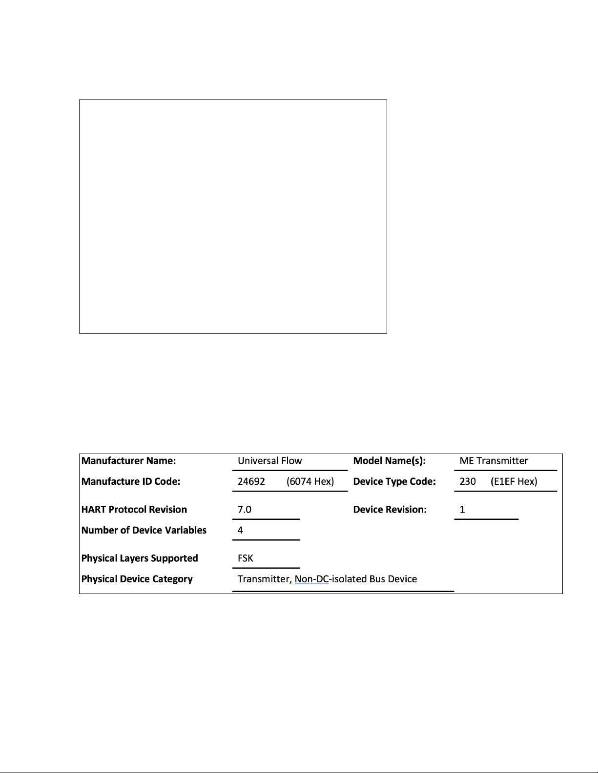
Figure 11: Device Identification
21Vane/Piston RX/RH
Page 22
4.4. Product Overview
The ME Transmitter is a two-wire loop-powered ow transmitter, with a 4 to 20 mA output. This transmitter
uses a non-contact magnetic encoder for measuring the displacement of the shaft/pointer on standard
UFM owmeters. It is an add-on feature to PI, LL, LP, LH, SN, SM, SH, MN, MM, MH, SX, MX, LN, LE and XHF
model ow meters as manufactured by Universal Flow Monitors, Inc. The ME Transmitter replaces the earlier
models Digital Transmitters that utilized a potentiometer, providing improved accuracy while maintaining 100%
compatibility. The analog output of this device is linear with ow over the working range of all supported
owmeters.
4.5. Process Interface
4.5.1. Magnetic Sensors
There are two built-in hall-effect sensors measuring the rotation of a permanent magnet that is mounted
onto the owmeter shaft. As the shaft rotates with ow, the sensors provide analog readings that are
in turn converted to a digital value by and A/D converter. The digital values are then processed by the
microcontroller and linearized, and subsequently converted to a scaled analog output via a D/A converter
in the range of 4 to 20 mA.
4.5.2. Host Interface: Process Flow
The two-wire 4 to 20 mA current loop is connected to two terminals on the transmitter circuit board.
Depending on the product used, one of the two congurations are offered for eld wiring.
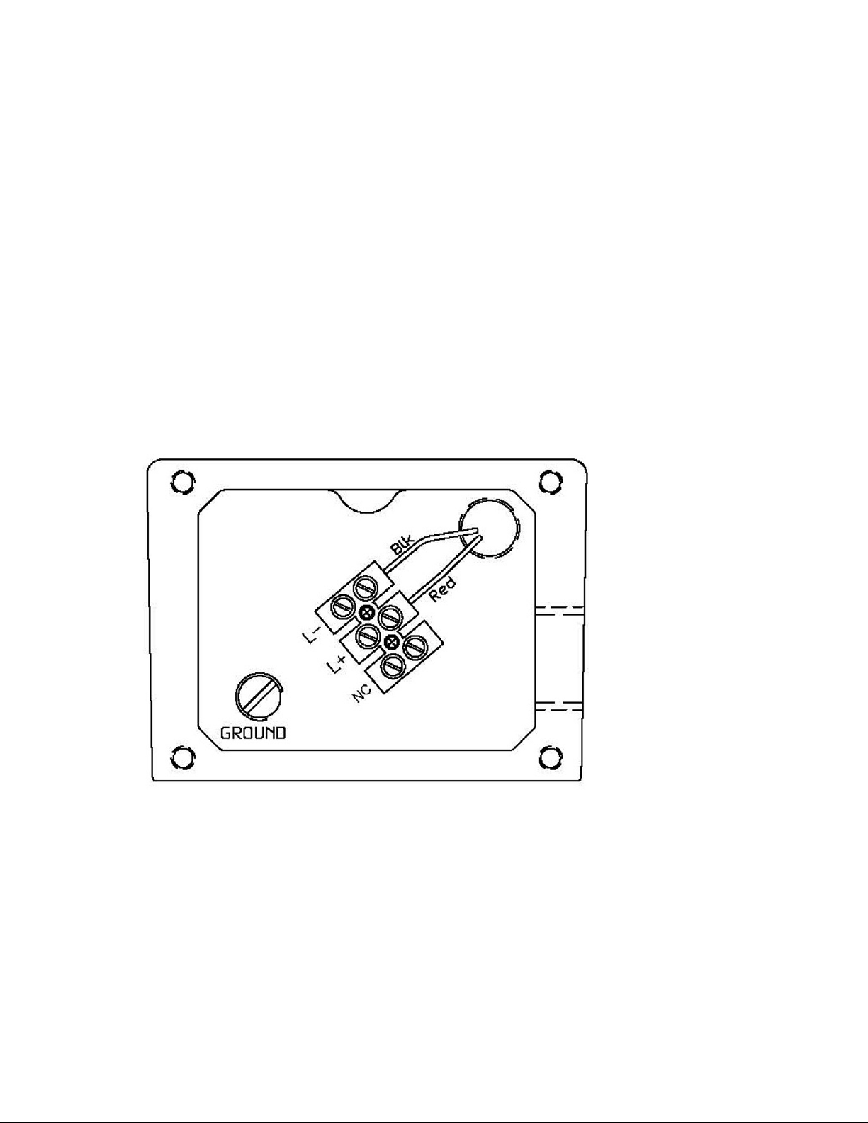
There is a secondary terminal strip away from the PCB (mounted in a separate compartment of the
owmeter) and is marked L+ and L-. The red wire connects the (+) terminal on the PCB to L+, and the
black wire connects the (–) terminal on the PCB to L-.
Figure 12: PCB wiring
This is the only output from this transmitter, representing the process ow measurement, linearized and
scaled according to the congured range of the instrument. This output corresponds to the Primary
Variable. HART Communication is supported on this loop.
22 UFM Vane Piston Consolidated Manual
Page 23

A guaranteed linear over-range is provided. The up-scale current of 24 mA can indicate device
malfunction. Current values are shown in the table below.
Linear over-range
Device malfunction
indication
Maximum current
Multi-Drop current draw
Lift-off voltage
4.6. Status Information
Bit Mask Denition Conditions to set bit
0x80(bit 7) Device Malfunction None
0x40(bit 6) Conguration Changed Any change in device conguration
0x20(bit 5) Cold start Set any time power is cycled
0x10(bit 4) More Status Available Triggers when either alarm is active
0x08(bit 3) Loop Current Fixed None
0x04(bit 2) Loop Current Saturated Occurs when loop current reaches upper limit
0x02(bit 1) Non-Primary Variable out of limits None
0x01(bit 0) Primary Variable Out of limits
Direction Values (percent of range) Values (mA or V)
Down 0% ± 0.5% 3.92 to 4.08 mA
Up +106.25% ± 0.1% 20.84 mA to 21.16 mA
Down N/A N/A
Up +125.0% ± 0.1% 23.98 mA to 24.02 mA
+106.25% ± 1% 20.84 mA to 21.16 mA
4.0 mA
10.5 V
Occurs when PV is being limited due to
exceeding calibrated limitations
When Bit 4 is set, Host should send Command 48 to determine which alarm is active.
4.6.1. Extended Device Status
The Field Device cannot predict when maintenance will be required. Extended Device Status is unused.
Byte Description Data
0-5 Device Specic Status Only Byte 0 is used
6 Extended Device Status Bit 1 will be set when an alarm condition is active.
7 Device Operating Mode 0
8 Standard Status 0
“Not used” bits are always set to 0.
Device does not support extended device status, all device status activity is included in the device status
byte.
23Vane/Piston RX/RH
Page 24

4.7. Universal Commands
All Universal Commands are supported as specied in the HART Universal Command Specication.
4.8. Common-Practice Supported Commands
The following common-practice commands are implemented:
33 Read Device Variables
35 Write Range Values
42 Perform Master Reset
44 Write PV Units
54 Read Device Variable Information
In command 54 the acquisition period is unused. Values are typically updated every 100 ms.
4.8.1. Command-Specific Response Codes
Code Class Description
0 Success No Command-Specic Errors
1-15 Undened
16 Error Access Restricted
17-31 Undened
32 Error Busy
33 -127 Undened
4.9. Command #130: Write High Alarm Setpoint
Writes the setpoint for the High Alarm.
4.9.1. Request Data Bytes
Byte Format Description
0-3 Float High Alarm Setpoint
4.9.2 . Response Data Bytes
Byte Format Description
0 Enum PV Unit value
1-4 Float High Alarm Setpoint
24 UFM Vane Piston Consolidated Manual
Page 25

4.9.3. Command-Specific Response Codes
Code Class Description
0 Success No Command-Specic Errors
1-15 Undened
16 Error Access Restricted
17-31 Undened
32 Error Busy
33 -127 Undened
4.10. Tables
4.10.1. Flow Unit Codes
Subset of HART Common Unit Codes
16 Gallons Per Minute (GPM)
17 Liters Per Minute (LPM)
19 Cubic Meters Per Hour (CMH)
4.10.2. Unit Conversion
Internally, the transmitter uses Gallons per Minute. Conversions are made using a oating point factor.
Values are directly converted from GPM when possible, however Alarm values changed between units are
converted from stored unit value:
New Unit Previous Unit Factor
GPM
LPM
CMH
LPM 0.2642
CMH 4.403
GPM 3.785
CMH 16.666
GPM 0.2271
LPM 0.06
4.11. Performance
4.11.1. Busy and Delayed-Response
Device busy is not used. Delayed-response is not used.
4.11.2. Long Messages
The largest data eld used is in the response to Command 21: 34 bytes including the two status bytes.
4.11.3. Non-Volatile Memory
EEPROM is used to hold the device’s conguration parameters. New data is written within 100ms of
command receipt.
4.11.4. Modes
Fixed current mode is not implemented.
25Vane/Piston RX/RH
Page 26

4.11.5. Write Protection
Write-protection is not implemented.
4.11.6. Damping
Damping is not implemented.
4.12. Default Configuration
Default conguration is based on a unit-by-unit basis.
26 UFM Vane Piston Consolidated Manual
Page 27

5. Vane/Piston - TX Transmitter / TH Transmitter with HART
Installation and Operation Manual Series: PI, LL, LP, LH, SN, SM, SH, MN, MM, MH, SX, MX, LN, LE and XHF Used
with T control boxes with 4 to 20 mA transmitter or HART and optional mechanical switches. Note: The 4 to 20 mA
transmitter with or without the LCD and with no switches is intrinsically safe with approved barriers.
Pointer, scale and 4 to 20 mA:
No Switches TX0
One SPDT (3 wire) TX1
Two SPDT (3 wire) TX2
One SPDT (4 wire) TX3
Two SPDT (4 wire) TX4
One SPDT (3 wire) high temperature TX61
Flow rate display, HART & 4 to 20 mA output
(HART protocol is not intrinsically safe):
HART & 4 to 20 mA output only TH0
One SPDT (3 wire) TH1
Two SPDT (3 wire) TH2
One SPDT (4 wire) TH3
Two SPDT (4 wire) TH4
PIPING: Screw pipe into meter with ow going into port marked “IN”.
Connect switch wires and/or open collector alarm and transmitter wires to the terminal
strip as shown.
WIRING:
CÂBLAGE
GROUNDING:
MISE À LA
TERRE
This section applies to all vane/piston meters that have the designator “TX0, 1, 2, 3, 4, or 61” in the model code.
This can be seen on the name plate as shown below.
Wire must be in accordance with all local and national codes. Wire size and insulation
ratings should support actual loads. In all cases, wire must be, as a minimum, 20 AWG
Teon insulated rated at 600 V and 200 ˚C. It is recommended to include a disconnect
switch or circuit breaker near this equipment.
Le câble doit être conforme à tous les codes locaux et nationaux. Le diamètre du câble
et ses niveaux d’isolation doivent pouvoir supporter des charges réelles. Dans tous les
cas, le câble doit être isolé au minimum en téon de calibre 20 AWG et d’une capacité
nominale de 600 V et de 200°C. Il est recommandé d’inclure un interrupteur général ou
un disjoncteur à proximité de cet équipement.
For protection against electrical shock in case of a fault, connect an external earth
ground to the grounding screws or lugs provided inside this instrument. Such attachment
points are identied with a tag or label adjacent to the grounding screw or lug with the
symbol.
Pour se protéger des chocs électriques en cas de défaut à la terre, brancher une mise
à la terre externe sur les vis ou cosses de mise à la terre fournies à l’intérieur de cet
instrument. De tels points de xation sont identiés à l’aide d’une étiquette ou d’un label
adjacent à la vis ou à la cosse de mise à la terre avec le symbole.
Figure 13: Name plate and Product ID
27Vane/Piston - TX Transmitter / TH Transmitter with HART
Page 28

Figure 14: T Box with optional switch and transmitter
28 UFM Vane Piston Consolidated Manual
Page 29

Figure 15: Transmitter wiring with out without HART
Figure 16: Mechanical (optional) switch wiring
29Vane/Piston - TX Transmitter / TH Transmitter with HART
Page 30
5.1. Installation
For best results, the meters may be installed in any position as long as proper piping installation requirements
are observed. This includes sufcient support of adjacent piping to minimize the system’s inherent vibration.
Unions of the same pipe size and full port isolation ball valves may be installed for ease of removal and
servicing of equipment, if necessary.
Figure 17: Maximum load resistance vs Supply voltage
5.2. Device Identification
5.3. Product Overview
The ME Transmitter is a two-wire loop-powered ow transmitter, with a 4 to 20 mA output. This transmitter
uses a non-contact magnetic encoder for measuring the displacement of the shaft/pointer on standard
UFM owmeters. It is an add-on feature to PI, LL, LP, LH, SN, SM, SH, MN, MM, MH, SX, MX, LN, LE and XHF
model ow meters as manufactured by Universal Flow Monitors, Inc. The ME Transmitter replaces the earlier
models Digital Transmitters that utilized a potentiometer, providing improved accuracy while maintaining 100%
compatibility. The analog output of this device is linear with ow over the working range of all supported
owmeters.
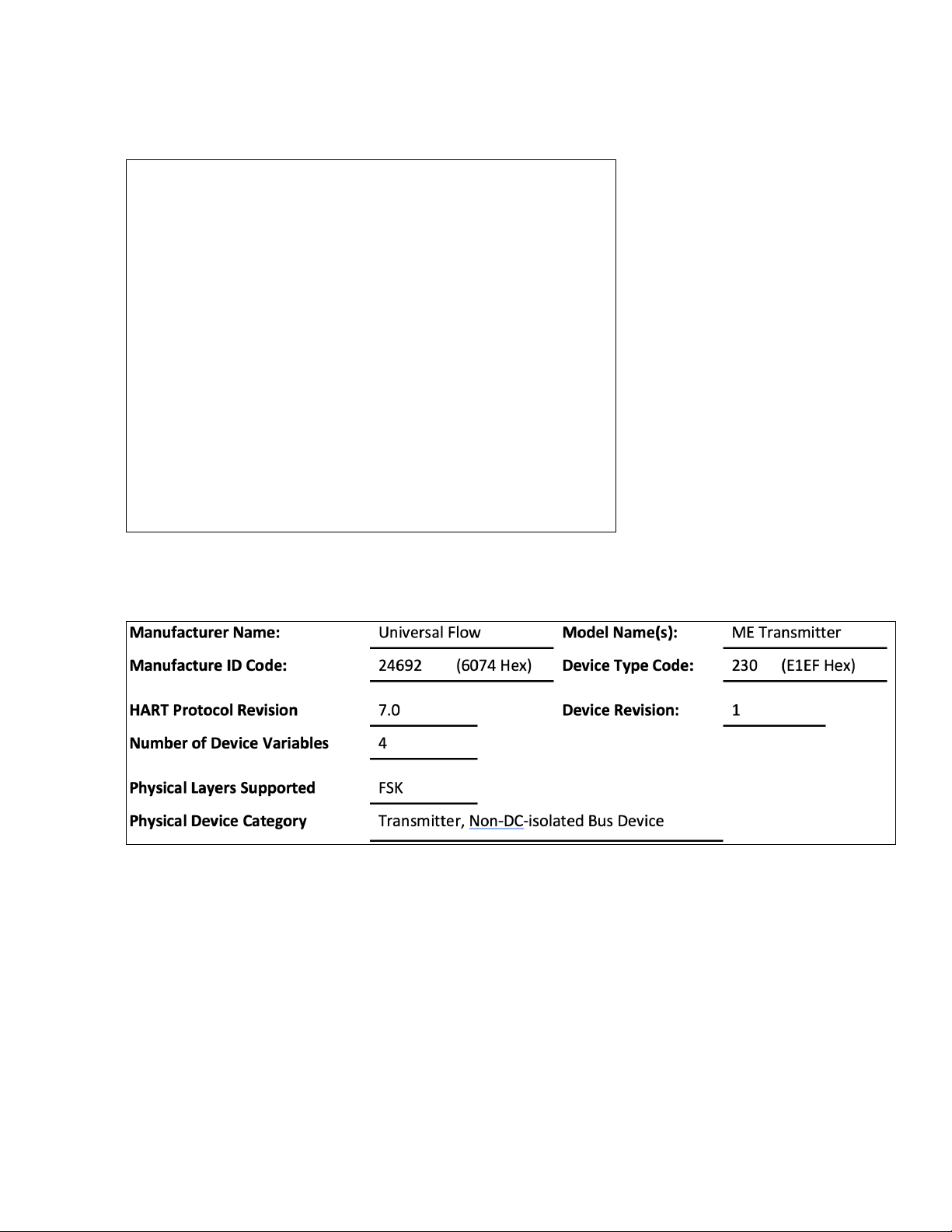
Figure 18: Device identification
30 UFM Vane Piston Consolidated Manual
Page 31
5.4. Process Interface
5.4.1. Magnetic Sensors
There are two built-in hall-effect sensors measuring the rotation of a permanent magnet that is mounted
onto the owmeter shaft. As the shaft rotates with ow, the sensors provide analog readings that are
in turn converted to a digital value by and A/D converter. The digital values are then processed by the
microcontroller and linearized, and subsequently converted to a scaled analog output via a D/A converter
in the range of 4 to 20 mA.
5.4.2. Host Interface: Process Flow
The two-wire 4 to 20 mA current loop is connected to two terminals on the transmitter circuit board.
Depending on the product used, one of the two congurations are offered for eld wiring.
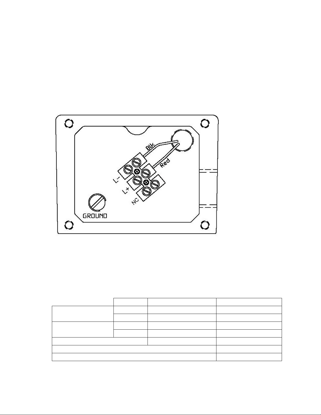
A secondary terminal strip away from the PCB (mounted in a separate compartment of the owmeter)
and is marked L+ and L-. The red wire connects the (+) terminal on the PCB to L+, and the black wire
connects the (–) terminal on the PCB to L-.
Figure 19: PCB wiring
This is the only output from this transmitter, representing the process ow measurement, linearized and
scaled according to the congured range of the instrument. This output corresponds to the Primary
Variable. HART Communication is supported on this loop.
A guaranteed linear over-range is provided. The up-scale current of 24 mA can indicate device
malfunction. Current values are shown in the table below.
Direction Values (percent of range) Values (mA or V)
Linear over-range
Device malfunction
indication
Maximum current
Multi-Drop current draw
Lift-off voltage
Down 0% ± 0.5% 3.92 to 4.08 mA
Up +106.25% ± 0.1% 20.84 mA to 21.16 mA
Down N/A N/A
Up +125.0% ± 0.1% 23.98 mA to 24.02 mA
+106.25% ± 1% 20.84 mA to 21.16 mA
4.0 mA
10.5 V
31Vane/Piston - TX Transmitter / TH Transmitter with HART
Page 32

5.5. Status Information
Bit Mask Denition Conditions to set bit
0x80(bit 7) Device Malfunction None
0x40(bit 6) Conguration Changed Any change in device conguration
0x20(bit 5) Cold start Set any time power is cycled
0x10(bit 4) More Status Available Triggers when either alarm is active
0x08(bit 3) Loop Current Fixed None
0x04(bit 2) Loop Current Saturated Occurs when loop current reaches upper limit
0x02(bit 1) Non-Primary Variable out of limits None
0x01(bit 0) Primary Variable Out of limits
When Bit 4 is set, Host should send Command 48 to determine which alarm is active.
5.5.1. Extended Device Status
The Field Device cannot predict, in advance, when the maintenance will be required. Extended Device
Status is unused.
Byte Description Data
0-5 Device Specic Status Only Byte 0 is used
6 Extended Device Status Bit 1 will be set when an alarm condition is active.
7 Device Operating Mode 0
8 Standard Status 0 Not used
Occurs when PV is being limited due to
exceeding calibrated limitations
“Not used” bits are always set to 0.
Device does not support extended device status, all device status activity is included in the device status
byte.
5.6. Universal Commands
All Universal Commands are supported as specied in the HART Universal Command Specication.
5.7. Common-Practice Supported Commands
The following common-practice commands are implemented:
33 Read Device Variables
35 Write Range Values
42 Perform Master Reset
44 Write PV Units
54 Read Device Variable Information
In command 54 the acquisition period is unused. Values are typically updated every 100ms.
5.7.1 . Burst Mode
This Field Device does not support Burst Mode.
5.7.2. Catch Device Variable
This Field Device does not support Catch Device Variable.
32 UFM Vane Piston Consolidated Manual
Page 33

5.8. Device-Specific Commands
The following device-specic commands are implemented:
128 Read Alarm Setpoints
129 Write Low Alarm Setpoint
130 Write High Alarm Setpoint
131 Reset Totalizer
5.9. Command #129: Write Low Alarm Setpoint
Writes the Setpoint for the Low Alarm.
5.9.1. Request Data Bytes
Byte Format Description
0-3 Float Low Alarm Setpoint
5.9.2. Response Data Bytes
Byte Format Description
0 Enum PV Unit value
1-4 Float Low Alarm Setpoint
5.9.3. Command-Specific Response Codes
Code Class Description
0 Success No Command-Specic Errors
1-15 Undened
16 Error Access Restricted
17-31 Undened
32 Error Busy
33 -127 Undened
5.10. Command #131: Reset Totalizer
Resets the totalizer to zero.
5.10.1. Request Data Bytes
Byte Format Description
None
33Vane/Piston - TX Transmitter / TH Transmitter with HART
Page 34

5.10.2. Response Data Bytes
Byte Format Description
None
5.10.3. Command-Specific Response Codes
Code Class Description
0 Success No Command-Specic Errors
1-15 Undened
16 Error Access Restricted
17-31 Undened
32 Error Busy
33 -127 Undened
5.11. Performance
5.11.1. Sampling Rates
Typical sampling rates are shown in the following table.
PV digital value calculation 10 per second
SV digital value calculation 10 per second
Analog output update 10 per second
5.11.2. Power-Up
The device is typically ready within 1 second of power-up. The totalizer is initialized to zero.
5.11.3. Reset
Command 42 (“Device Reset”) causes the device to reset its microcontroller. The resulting restart is
identical to the normal power up sequence.
5.11.4. Self-Test
Self-Test is not supported.
5.11.5. Command Response Times
Minimum 20 ms
Typ ical 50 ms
Maximum 10 0 ms
34 UFM Vane Piston Consolidated Manual
Page 35

5.12. Capability Checklist
Manufacturer, model and revision Universal Flow, ME Transmitter, Rev1
Device type Transmitter
HART revision 7.0
Device Description available No
Number and type of sensors 2 internal
Number and type of actuators 0
Number and type of host side signals 1: 4 to 20 mA analog
Number of Device Variables 4
Number of Dynamic Variables 2
Mappable Dynamic Variables? No
Number of common-practice commands 5
Number of device-specic commands 4
Bits of additional device status 2
Alternative operating modes? No
Burst mode? No
Write-protection? No
35Vane/Piston - TX Transmitter / TH Transmitter with HART
Page 36

6. Vane/Piston TXL
Installation and Operation Manual Series: PI, LL, LP, LH, SN, SM, SH, MN, MM, MH, SX, MX, LN, LE and XHF. Note:
The TXL0 4 to 20 mA transmitter with or without the LCD and with no switches is intrinsically safe with approved
barriers.
LCD readout, 4 to 20 mA with 2 open
collectors:
No switches TXL0
One SPDT (3 wire) TXL1
One SPDT (4 wire) TXL3
One SPDT (3 wire) high temperature TXL61
6.1. Name Plate and Product ID
This manual applies to all vane/piston meters that have the designator “TXL0, 1, 3, or 61” in the model code.
This can be seen on the name plate as shown below.
Figure 20: Name plate example
Figure 21: Terminal strip for power and 4 to 20 mA signal
36 UFM Vane Piston Consolidated Manual
Page 37

PIPING: Screw pipe into meter with ow going into port marked “IN”.
Connect switch wires and/or open collector alarm and transmitter wires to the terminal
strip as shown.
WIRING:
CÂBLAGE
GROUNDING:
MISE À LA
TERRE
A typical 4 to 20 mA wiring diagram is shown below:
Wire must be in accordance with all local and national codes. Wire size and insulation
ratings should support actual loads. In all cases, wire must be, as a minimum, 20 AWG
Teon insulated rated at 600 V and 200 ˚C. It is recommended to include a disconnect
switch or circuit breaker near this equipment.
Le câble doit être conforme à tous les codes locaux et nationaux. Le diamètre du câble
et ses niveaux d’isolation doivent pouvoir supporter des charges réelles. Dans tous les
cas, le câble doit être isolé au minimum en téon de calibre 20 AWG et d’une capacité
nominale de 600 V et de 200°C. Il est recommandé d’inclure un interrupteur général ou
un disjoncteur à proximité de cet équipement.
For protection against electrical shock in case of a fault, connect an external earth
ground to the grounding screws or lugs provided inside this instrument. Such attachment
points are identied with a tag or label adjacent to the grounding screw or lug with the
symbol.
Pour se protéger des chocs électriques en cas de défaut à la terre, brancher une mise
à la terre externe sur les vis ou cosses de mise à la terre fournies à l’intérieur de cet
instrument. De tels points de xation sont identiés à l’aide d’une étiquette ou d’un label
adjacent à la vis ou à la cosse de mise à la terre avec le symbole.
Figure 22: 4 to 20 mA wiring diagram and load resistor vs power supply diagram
A guaranteed linear over-range is provided. Device malfunction can be indicated by the up-scale current of
24 mA. Current values are shown in the table below.
Direction Values (percent of range) Values (mA or V)
Linear over-range
Device malfunction
indication
Maximum current
Multi-Drop current draw
Lift-off voltage
Down 0% ± 0.5% 3.92 to 4.08 mA
Up +106 .25% ± 0.1% 20.84 mA to 21.16 mA
Down N/A N/A
Up +125.0% ± 0.1% 23.98 mA to 24.02 mA
+106.25% ± 1% 20.84 mA to 21.16 mA
4.0 mA
10.5 V
37Vane/Piston TXL
Page 38

1. After the last digit is set, continue holding A2 until “SEt” is displayed. If you want to change the rst digit
again, do not hold A2. Momentarily press and release A2 and the rst digit starts blinking again.
2. When nished recording the new setpoint (“SEt” is displayed), release A2.
Figure 23: Press and release A2
Note: Valid setpoint range is 0-100% of full-scale ow. If the alarm value is set higher than full-scale, it is
clamped at full-scale upon exiting this menu.
To disable the alarm, set its value to zero.
The red ALARM 1 LED comes on when ow exceeds this setpoint. This LED is in series with the drive circuit
for the high-alarm open-collector output, meaning that the output transistor is active whenever this LED is on.
Some models do not have any external wiring that connects to the alarm transistor (see Model Codes).
In this example, the high alarm had been set for 80.0; therefore, the red LED was activated when ow reached
80.1.
The LED turns off when ow < (setpoint – hysteresis). Hysteresis is 5% of full-scale.
Figure 24: LED activation example
6.2. Set Low Flow Alarm
Figure 25: Set Low Flow alarm
1. Press A2 until “LFLo” is displayed, then release A2.
38 UFM Vane Piston Consolidated Manual
Page 39

7. Device Dimension Drawings
Figure 26: Vane/Piston H0 - Transmitter with HART PI, LL, LP, and LH dimensions
Figure 27: Vane/Piston - XØ Transmitter PI, LL, LP, and LH dimensions
Figure 28: Vane/Piston - XØ Transmitter SX, SN, SM, and SH dimensions
39Device Dimension Drawings
Page 40
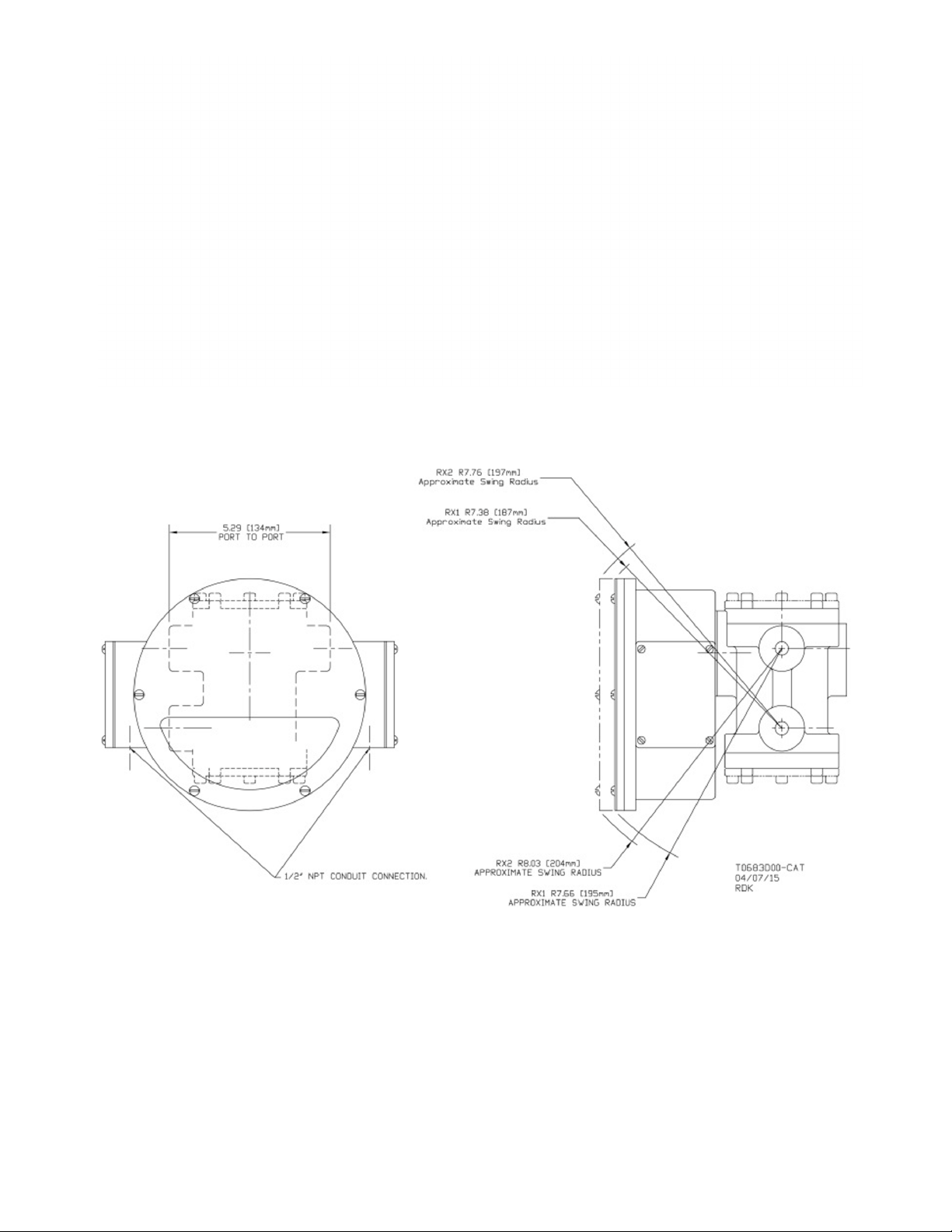
Figure 29: Vane/Piston - XØ Transmitter MN, MM, MH, and MX dimensions
Figure 30: Vane/Piston RX/RH PI, LL, LP, and LH dimensions
40 UFM Vane Piston Consolidated Manual
Page 41
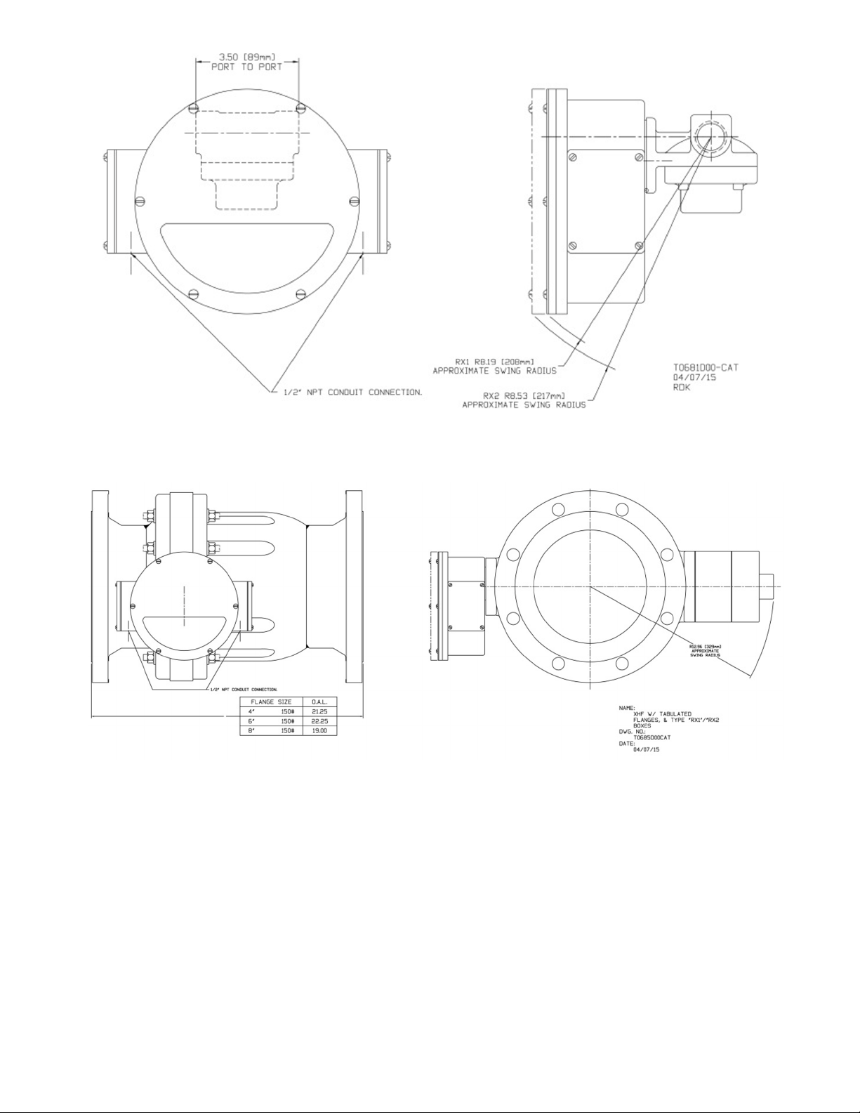
Figure 31: Vane/Piston RX/RH SX, SN, SM, and SH dimensions
Figure 32: Vane/Piston RX/RH XHF dimensions
41Device Dimension Drawings
Page 42
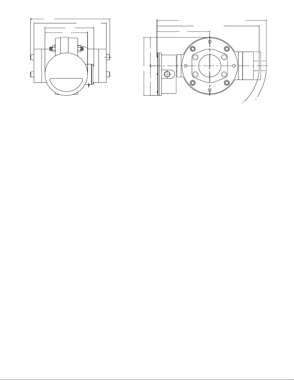
7.63
14.19
19.56 (4 SPINGS for FLOW RATES GREATER
400 and 500 GPM
8.75
12.94
PORT TO PORT
THAN 300 GPM, 1200 LPM, or 70 CMH)
9.44
5.13
10.44
REF
5.31
1/2" NPT CONDUIT CONNECTION
BOX TYPES RP, RT, RTV, & RTZ
R10.16 APPROXIMATE SWING RADIUS
Figure 33: Vane/Piston RX/RH LE and LN dimensions
18.28 (2 SPRINGS)
R8.88 APPROX. SWING RADIUS
Figure 34: Vane/Piston - TX Transmitter / TH Transmitter with HART LL, LP, and LH dimensions
42 UFM Vane Piston Consolidated Manual
Page 43

Figure 35: Vane/Piston - TX Transmitter / TH Transmitter with HART SX, SN, SM, and SH dimensions
Figure 36: Vane/Piston - TX Transmitter / TH Transmitter with HART XHF dimensions
43Device Dimension Drawings
Page 44
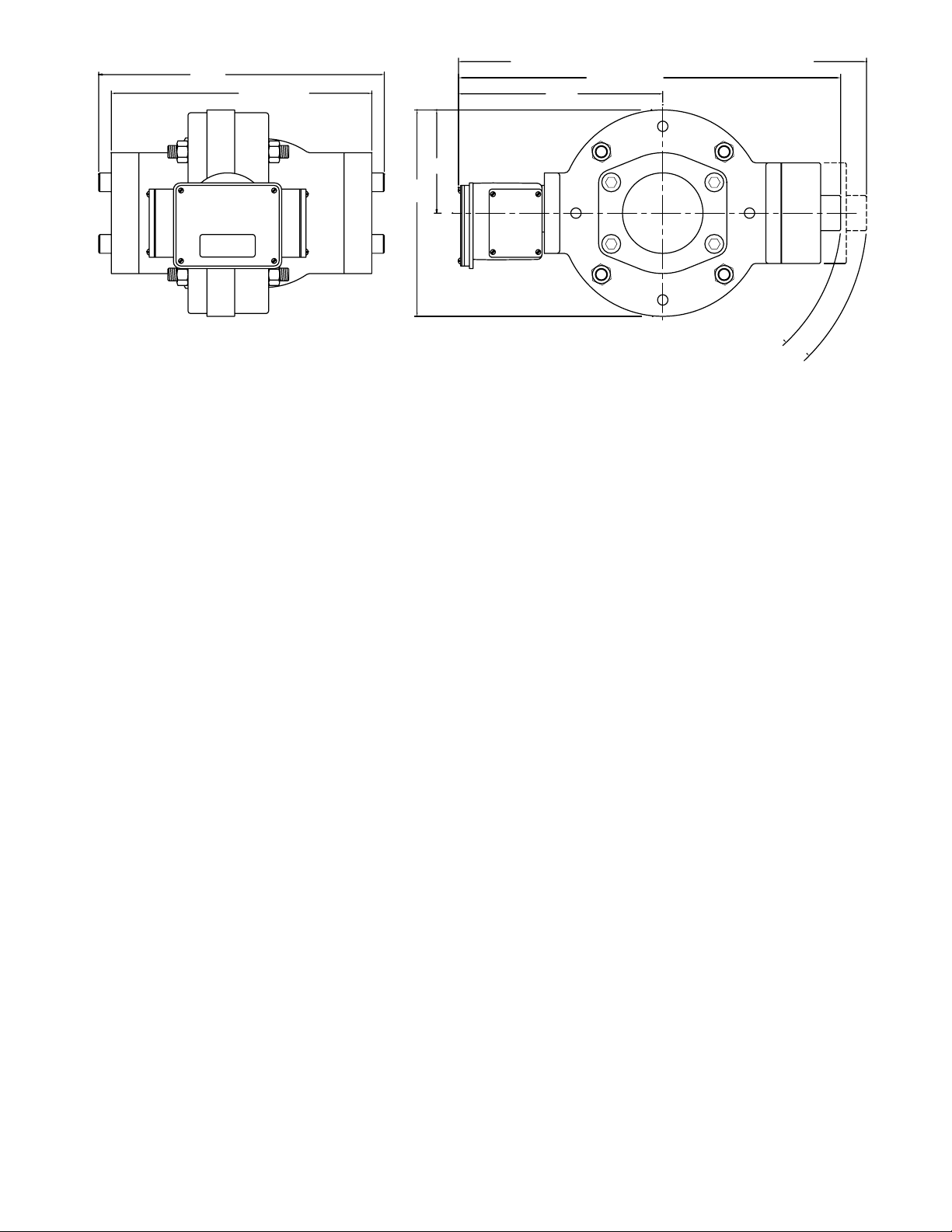
14.19
20.27 (4 Springs for flow rates greater than 300 GPM, 1200 LPM, or 70 CMH)
400 and 500 GPM.
12.94
PORT TO PORT
18.99 (2 Springs)
10.15
5.13
10.25
REF
R8.88 APPROXIMATE SWING RADIUS.
R10.16 APPROXIMETE SWING RADIUS.
Figure 37: Vane/Piston TX/TH LE and LN dimensions
44Device Dimension Drawings
Page 45

8. Compliance and Certifications
This device complies with part 15 of the FCC Rules. Operation is subject to the following two conditions: (1) This
device may not cause harmful interference, and (2) this device must accept any interference received, including
interference that may cause undesired operation. Changes or modications not expressly approved by the party
responsible for compliance could void the user’s authority to operate the equipment.
Note:
This equipment has been tested and found to comply with the limits for a Class A digital device, pursuant to part
15 of the FCC Rules. These limits are designed to provide reasonable protection against harmful interference
when the equipment is operated in a commercial environment. This equipment generates, uses, and can radiate
radio frequency energy and, if not installed and used in accordance with the instruction manual, may cause
harmful interference to radio communications. Operation of this equipment in a residential area is likely to cause
harmful interference in which case the user will be required to correct the interference at his own expense.
CAN ICES-003(A) / NMB-003(A)
This Class A digital apparatus complies with Canadian ICES-003
Cet appareil numérique de la classe A est conforme à la norme NMB-003 du Canada
Due to the sensitive nature of the product, errors may be encountered in the presence of high frequency electro-
magnetic elds.
If it suspected this equipment has errors due to electro-magnetic eld interference, the user is encouraged to
correct the interference by one or more of the following measures:
- Reorient or relocate the electro-magnetic eld transmitter. Sources include: Cell phones, Wi-Fi Routers or
business radios.
- Use shielded wires on the 4 to 20 mA cables.
- Contact UFM costumer support for help.
45 UFM Vane Piston Consolidated Manual
Page 46

WARRANTY/DISCLAIMER
OMEGA ENGINEERING, INC. warrants this unit to be free of defects in materials and workmanship for a period
of 13 months from date of purchase. OMEGA’s WARRANTY adds an additional one (1) month grace period to
the normal one (1) year product warranty to cover handling and shipping time. This ensures that OMEGA’s
customers receive maximum coverage on each product.
If the unit malfunctions, it must be returned to the factory for evaluation. OMEGA’s Customer Service
Department will issue an Authorized Return (AR) number immediately upon phone or written request.
Upon examination by OMEGA, if the unit is found to be defective, it will be repaired or replaced at no charge.
OMEGA’s WARRANTY does not apply to defects resulting from any action of the purchaser, including but
not limited to mishandling, improper interfacing, operation outside of design limits, improper repair, or
unauthorized modification. This WARRANTY is VOID if the unit shows evidence of having been tampered
with or shows evidence of having been damaged as a result of excessive corrosion; or current, heat,
moisture or vibration; improper specification; misapplication; misuse or other operating conditions outside
of OMEGA’s control. Components in which wear is not warranted, include but are not limited to contact
points, fuses, and triacs.
OMEGA is pleased to offer suggestions on the use of its various products. However, OMEGA neither assumes
responsibility for any omissions or errors nor assumes liability for any damages that result from the use of its
products in accordance with information provided by OMEGA, either verbal or written. OMEGA warrants only
that the parts manufactured by the company will be as specified and free of defects. OMEGA MAKES NO OTHER
WARRANTIES OR REPRESENTATIONS OF ANY KIND WHATSOEVER, EXPRESSED OR IMPLIED, EXCEPT THAT OF
TITLE, AND ALL IMPLIED WARRANTIES INCLUDING ANY WARRANTY OF MERCHANTABILITY AND FITNESS FOR
A PARTICULAR PURPOSE ARE HEREBY DISCLAIMED. LIMITATION OF LIABILITY: The remedies of purchaser set
forth herein are exclusive, and the total liability of OMEGA with respect to this order, whether based on contract,
warranty, negligence, indemnification, strict liability or otherwise, shall not exceed the purchase price of the
component upon which liability is based. In no event shall OMEGA be liable for consequential, incidental or
special damages.
CONDITIONS: Equipment sold by OMEGA is not intended to be used, nor shall it be used: (1) as a “Basic
Component” under 10 CFR 21 (NRC), used in or with any nuclear installation or activity; or (2) in medical
applications or used on humans. Should any Product(s) be used in or with any nuclear installation or activity,
medical application, used on humans, or misused in any way, OMEGA assumes no responsibility as set
forth in our basic WARRANTY/DISCLAIMER language, and, additionally, purchaser will indemnify OMEGA
and hold OMEGA harmless from any liability or damage whatsoever arising out of the use of the Product(s)
in such a manner.
RETURN REQUESTS/INQUIRIES
Direct all warranty and repair requests/inquiries to the OMEGA Customer Service Department. BEFORE
RETURNING ANY PRODUCT(S) TO OMEGA, PURCHASER MUST OBTAIN AN AUTHORIZED RETURN (AR)
NUMBER FROM OMEGA’S CUSTOMER SERVICE DEPARTMENT (IN ORDER TO AVOID PROCESSING
DELAYS). The assigned AR number should then be marked on the outside of the return package and on any
correspondence.
The purchaser is responsible for shipping charges, freight, insurance and proper packaging to prevent
breakage in transit.
FOR WARRANTY RETURNS, please have the
following information available BEFORE contacting
OMEGA:
1. Purchase Order number under which the product
was PURCHASED,
2. Model and serial number of the product under
warranty, and
3. Repair instructions and/or specific problems
relative to the product.
OMEGA’s policy is to make running changes, not model changes, whenever an improvement is possible. This affords our customers the latest
in technology and engineering.
OMEGA is a trademark of OMEGA ENGINEERING, INC. © Copyright OMEGA ENGINEERING, INC. All rights reserved. This document may not
be copied, photocopied, reproduced, translated, or reduced to any electronic medium or machine-readable form, in whole or in part, without
the prior written consent of OMEGA ENGINEERING, INC.
FOR NON-WARRANTY REPAIRS,
consult OMEGA
for current repair charges. Have the following
information available BEFORE contacting OMEGA:
1. Purchase Order number to cover the COST
of the repair,
2. Model and serial number of the product, and
3. Repair instructions and/or specific problems
relative to the product.
Page 47

dwyer-inst.com
®
©Copyright 2024 Dwyer Instruments, LLC Printed in U.S.A. 9/24
Improving the world, one measurement at a time.
TM
UNIVERSAL
FLOW MONITORS
FR#: 444744-00 Rev. 1
 Loading...